US4771652A - Manipulator-head drive assembly - Google Patents
Manipulator-head drive assemblyDownload PDFInfo
- Publication number
- US4771652A US4771652AUS06/944,440US94444086AUS4771652AUS 4771652 AUS4771652 AUS 4771652AUS 94444086 AUS94444086 AUS 94444086AUS 4771652 AUS4771652 AUS 4771652A
- Authority
- US
- United States
- Prior art keywords
- segment
- axis
- shaft
- relative
- transmission
- Prior art date
- Legal status (The legal status is an assumption and is not a legal conclusion. Google has not performed a legal analysis and makes no representation as to the accuracy of the status listed.)
- Expired - Fee Related
Links
Images


Classifications
- B—PERFORMING OPERATIONS; TRANSPORTING
- B25—HAND TOOLS; PORTABLE POWER-DRIVEN TOOLS; MANIPULATORS
- B25J—MANIPULATORS; CHAMBERS PROVIDED WITH MANIPULATION DEVICES
- B25J3/00—Manipulators of leader-follower type, i.e. both controlling unit and controlled unit perform corresponding spatial movements
- B—PERFORMING OPERATIONS; TRANSPORTING
- B25—HAND TOOLS; PORTABLE POWER-DRIVEN TOOLS; MANIPULATORS
- B25J—MANIPULATORS; CHAMBERS PROVIDED WITH MANIPULATION DEVICES
- B25J17/00—Joints
- B25J17/02—Wrist joints
- B25J17/0283—Three-dimensional joints
- B25J17/0291—Three-dimensional joints having axes crossing at an oblique angle, i.e. other than 90 degrees
- B—PERFORMING OPERATIONS; TRANSPORTING
- B25—HAND TOOLS; PORTABLE POWER-DRIVEN TOOLS; MANIPULATORS
- B25J—MANIPULATORS; CHAMBERS PROVIDED WITH MANIPULATION DEVICES
- B25J17/00—Joints
- B25J17/02—Wrist joints
- Y—GENERAL TAGGING OF NEW TECHNOLOGICAL DEVELOPMENTS; GENERAL TAGGING OF CROSS-SECTIONAL TECHNOLOGIES SPANNING OVER SEVERAL SECTIONS OF THE IPC; TECHNICAL SUBJECTS COVERED BY FORMER USPC CROSS-REFERENCE ART COLLECTIONS [XRACs] AND DIGESTS
- Y10—TECHNICAL SUBJECTS COVERED BY FORMER USPC
- Y10T—TECHNICAL SUBJECTS COVERED BY FORMER US CLASSIFICATION
- Y10T74/00—Machine element or mechanism
- Y10T74/19—Gearing
- Y—GENERAL TAGGING OF NEW TECHNOLOGICAL DEVELOPMENTS; GENERAL TAGGING OF CROSS-SECTIONAL TECHNOLOGIES SPANNING OVER SEVERAL SECTIONS OF THE IPC; TECHNICAL SUBJECTS COVERED BY FORMER USPC CROSS-REFERENCE ART COLLECTIONS [XRACs] AND DIGESTS
- Y10—TECHNICAL SUBJECTS COVERED BY FORMER USPC
- Y10T—TECHNICAL SUBJECTS COVERED BY FORMER US CLASSIFICATION
- Y10T74/00—Machine element or mechanism
- Y10T74/20—Control lever and linkage systems
Definitions
- the present inventionrelates to a robot or manipulator. More particularly, this invention concerns a drive assembly for such a manipulator.
- a standard manipulatorhas a stationary base on which a carousel can be rotated about a vertical axis by a motor mounted on the base.
- a main support armis pivotal on the carousel about an inner horizontal axis perpendicularly intersecting the vertical axis by means of another motor mounted on the carousel.
- a counterweightis provided for counterbalancing the offcenter weight of the main arm and the structure carried by it.
- the outer or upper end of the main armcarries an outrigger arm rotatable on the main arm about an outer horizontal axis by means of yet another motor carried on the main arm.
- the outer end of this outrigger armin turn carries a so-called head assembly that in turn carries the tool, for instance a welding electrode.
- This head assemblyitself comprises inner, intermediate, and front segments pivotal about respective axes, with the outer and inner axes forming with the intermediate axis respective outwardly and inwardly open acute angles.
- the inner side of the rear segmentcarries the drive shafts for the head parts and also for a tool holder concentric to the front segment.
- Drives with high stepdowns, at least 50:1connect the shafts to the respective parts while bevel gearing connects succeeding shafts to one another.
- This arrangementis supposed to provide the maximum reach for the tool while being as compact as possible.
- the relative inclinations of the various axesit is possible to direct the tool from the front segment inward back toward the support formed normally by the outer end of the outer arm.
- the toolcan lie on an axis parallel to the base axis, which typically is the longitudinal axis of the outer arm, and can point from the outer head part back to the base.
- the shaftscan be fairly slim and compact since the high stepdown at the outermost point in the gear train makes any minor losses or inefficiencies that exist upstream in the drive train inconsequential. Slip of, for instance, 1° in an upstream gear train is reduced by a standard harmonic transmission with a 100:1 ratio to 0.01°, a normally negligible amount.
- the transmissionsare of the high-ratio and extremely compact harmonic type which basically have three parts.
- the rear segment or so-called wave generatoris of elliptical section and supports via an array of rollers a flexible toothed belt or so-called flexspline having external teeth that mesh at two diametrically opposite locations with two juxtaposed ring gears.
- One of these ring gearsis called the circular spline, is normally fixed, and normally has two more teeth than the flexspline.
- the other ring gearis called the dynamic spline, is normally rotatable, but has the same number of teeth as the flexspline.
- Such a transmissionis extremely compact and is capable of transmitting considerable torque. In addition it has very little slip, and converts torque purely into torque so that it does not load the support bearings radially or axially.
- the ratio in such a transmissionis normally at least 80:1.
- Another objectis the provision of such a manipulator-head drive assembly which overcomes the above-given disadvantages, that is which allows the position of the tool on the front segment to be calculated fairly easily and which makes it easy to provide a separate drive shaft for a tool support on the front head segment.
- a head assembly for a manipulatorhas an rear segment rotatable about an inner or rear segment axis fixed relative to the manipulator and extending through the rear segment, an intermediate segment supported on on the rear segment for rotation about an intermediate axis defined by the rear segment and intersecting the rear axis at an acute intermediate angle open away from the rear segment, and a front segment having a holder adapted to carry a tool and supported on the intermediate segment for rotation about a front segment axis fixed relative to the intermediate segment, extending through the front segment, and intersecting the rear axis at an acute outer angle open away from the intermediate segment.
- a driverotates the intermediate and front segments on the inner and intermediate segments about the respective intermediate and front axes.
- the drivehas an intermediate shaft extending along the intermediate axis, an outer shaft extending along the front axis, angle gearing interconnecting the intermediate and outer shafts for joint synchronous rotation, an intermediate stepdown transmission with a high stepdown ratio of N:1 connected between the intermediate shaft and the intermediate segment for relatively slowly rotating the intermediate segment relative to the intermediate shaft, and an outer stepdown transmission with a high stepdown ratio of (N+/-1):1 connected between the outer shaft and the front segment for rotating on the intermediate segment.
- the ratiois determined both by the relative numbers of teeth and whether the output is taken off the circular or dynamic spline, as invariably the wave generator is the driven input member.
- the difference in signindicates that the output directions are opposite.
- both of the transmissionswhich are of the harmonic type, are oppositely connected with respect to their circular and dynamic splines to achieve the difference in stepdown.
- the assembly of the inventioncan also have a tool holder rotatable on the front segment about an axis intersecting the outer axis and forming therewith a tool angle open away from the intermediate segment, respective secondary inner or rear, intermediate, and outer or front shafts extending along the respective axes in the respective segments, and secondary angle gearing interconnecting the secondary shafts in a train with the tool holder for joint rotation.
- a tool held by this holdercan be rotated so that when this tool is not straight yet another degree of motion is obtained.
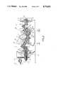
- FIG. 1is a mainly schematic side view illustrating a manipulator head assembly according to this invention
- FIG. 2is a longitudinal section through the assembly of this invention
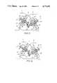
- FIG. 3is a detail view of the center of FIG. 2;
- FIG. 4is a detail view through the center of a second embodiment of the assembly
- FIG. 5is a detail view through the center of a third embodiment of the assembly.
- FIG. 6is a detail view through the center of a fourth embodiment of the assembly.
- FIG. 7is a detail view through the center of a fifth embodiment of the assembly.
- FIG. 8is a detail view through the center of a sixth embodiment of the assembly.
- the head assemblybasically comprises inner, intermediate, and front segments 1, 2, and 3 that are centered on respective axes 1A, 2A, and 3A and that abut each other flatly at planes P and P' which intersect at an angle of 60°.
- the inner or rear segment 1is mounted on a support part or outrigger arm indicated schematically at 8 for pivoting thereon about its axis 1A which is always coaxial with the axis 4 of the support 8.
- the intermediate segment 2pivots on the outer end of the segment 1 about an axis 5 perpendicular to the plane P and intersecting the axis 1A on the plane P.
- the outer or front segment 3pivots on the outer end of the segment 2 about an axis 6 perpendicular to the plane P' and intersecting the axes 2A and 3A on the plane P'.
- the two axes 5 and 6intersect at a point offset from the axis 2A.
- the axes 1A, 2A, 3A, and 4are coaxial and the axes 5 and 6 form the sides and axis 2A the base of an isosceles triangle (shown inverted).
- the axes 5 and 6extend in the FIG. 1 position at the angle ⁇ of 30° to the respective axes 1A and 3A, and the axes 5 and 6 extend at an obtuse angle to each other, although they need not be symmetrical as illustrated.
- the front segment 3is formed with a cylindrical tool holder 7 on which is mounted a tool shown schematically at T.
- This tool Tcan be a welding electrode, scribe, or the like.
- the base or support part 8is provided at its axis 4 with a central shaft 20 surrounded by two tube shafts 14 and 13.
- the outer tube shaft 13has on its inner input end a gear 11 that meshes with a gear 10 carried on a shaft 9 parallel to the axis 4 and on its output end is connected via a high-ratio harmonic transmission 12 to the inner end of the segment 1.
- rotation of the shaft 9will rotate the segment 1 about the axis 1A, 4.
- the tube shaft 14has an outer end connected via bevel gears 15 to the inner end of a core shaft 16 extending along the axis 5 and in turn having an outer end connected via bevel gears 18 to another core shaft 17 extending along the axis 6.
- the outer end of the shaft 17is in turn connected via bevel gears 19 with the inner end of a shaft 32 extending along the axis 3A and connected at its outer end to the tool holder 7 via another high-ratio harmonic transmission 31.
- high-speed rotation of the shaft 14will be transmitted via the shafts 16 and 17 to the shaft 32 and thence via the transmission 31 to the tool holder 7 to rotate it about its axis 3A.
- the gear pairs 15, 18, and 19transmit the rotation regardless of the relative positions of the axes of the system.
- the core shaft 20has an outer end connected via bevel gears 21 with the inner end of a tube shaft 22 coaxially around the shaft 16 and having a central portion connected via another harmonic transmission 25 to the segment 2 and an outer end connected via bevel gears 23 with another tube shaft 24 coaxially surrounding the shaft 17 and connected via a further harmonic transmission 26 to the segment 3.
- Both shafts 22 and 24are supported by bearings in the intermediate segment 2.
- the transmission 25is braced on the rear segment 1 and rotates the intermediate segment 2 relative to the rear segment 1 at a ratio i of x and the transmission 26 is braced on the intermediate segment 2 and rotates the front segment 3 relative to the intermediate segment 2 at a ratio i of (x-1).
- the gearingis such that the rotation direction 29 of the front segment 3 is opposite the rotation direction 30 of the shaft 24.
- this differenceis obtained in the transmission 25 by driving the wave generator WG with the shaft 22, by securing the dynamic spline DS (the ring gear with the same number of teeth as the flexspline) on the rear segment 1, securing the circular spline CS (the ring gear with more teeth than the flexspline) on the segment 2, and using a stepdown of 101:1 by having 200 teeth on the dynamic spline DS and 202 teeth on the circular spline CS.
- the transmission 26is oppositely set up with a 202-tooth circular spline CS fixed on the intermediate segment 2 and a 200-tooth dynamic spline DS secured to the front segment 3 and using a stepdown of 100:1.
- the rotation of the segment 3 as shown by arrow 29is opposite to the rotation direction of the segment 2 as shown by arrow 30.
- the rotation directions 33 and 34 of the shaft 22 and segment 2are the same as the direction 30.
- the difference between the two stepdown ratios iis effected by the relative movement of the segments 2 and 3 whose gears 23 roll compensatingly off on each other.
- FIG. 4the rotation of the segments 2 and 3 is in the same direction.
- the transmission 25is set up as in FIG. 3, with its dynamic spline DS secured to the segment 1 and circular spline CS to the segment 2 for a 101:1 reduction and codirectional rotation of the shaft 22 and segment 2.
- the other transmission 26is also set up identically to FIG. 3, with its circular spline CS on the segment 2 and dynamic spline DS on the segment 3 for a 100:1 reduction and opposite rotation of the shaft 24 and segment 3.
- the tool holder 7does not need to be rotated so that the shafts 22' and 24' are core shafts.
- the kinematics of the FIG. 5 arrangementare otherwise identical to that of FIG. 4, with both 202-teeth circular splines CS of both transmissions 25 and 26 being on the segment 2 and the 200-teeth dynamic splines DS being on the segments 1 and 3.
- gears 23are identical but mesh laterally for a change in direction like that effected by the gear 27 so that the direction 29' is identical to the directions 33 and 34.
- a 202-teeth dynamic spline DS of the transmission 26'is fixed on the seqment 2 and a 204-teeth circular spline CS is fixed on the segment 3 for rotation of the segments 2 and 3 in the opposite directions, as in FIG. 3.
- stepdown transmission 25'once again has a stepdown that is one revolution more than that of the stepdown transmission 26'.
- FIG. 7shows an arrangement wherein the same parts are used as in FIG. 6, plus a reversing gear 27' between the gears 23 so that the relative directions correspond to those of FIG. 3, that is the segments 2 and 3 rotate equally but oppositely.
- the gear 27'therefore compensates for the relative movement of these segments 2 and 3.
- FIG. 8the system is identical to that of FIG. 7 except that the outer transmission 26' is reversed as in FIG. 6 with its circular spline CS on the segment 3 and its dynamic spline DS is on the segment 2.
- the segment 3rotates in direction 29' which is the same as the directions 33 and 34 of the shaft 22 and segment 2.
- FIGS. 3 through 8would also work if the dynamic splines and circular splines of each transmission were switched with one another. This would give the transmission 25 a ratio i of (x-1) and the transmission 26 the ratio i of x. The result would be opposite rotation of the segments 2 and 3 from that illustrated. It is also within the scope of this invention to use transmissions other than of the harmonic type, for instance planetary ones, to achieve the novel effect of this invention.
Landscapes
- Engineering & Computer Science (AREA)
- Robotics (AREA)
- Mechanical Engineering (AREA)
- Manipulator (AREA)
- Retarders (AREA)
- Gear Transmission (AREA)
- Supporting Of Heads In Record-Carrier Devices (AREA)
Abstract
Description
i=n.sub.WG /n.sub.DS =Z.sub.DS /(Z.sub.DS -Z.sub.CS)=200/-2=-100.
i=n.sub.WG /n.sub.CS =Z.sub.CS /(Z.sub.CS -Z.sub.DS)=202/2=+101.
i=Z.sub.CS /(Z.sub.CS -Z.sub.DS)=204/(204-202)=102.
Claims (5)
Applications Claiming Priority (2)
| Application Number | Priority Date | Filing Date | Title |
|---|---|---|---|
| DE19853545068DE3545068A1 (en) | 1985-12-19 | 1985-12-19 | TRANSMISSION HEAD FOR MANIPULATORS |
| DE3545068 | 1985-12-19 |
Publications (1)
| Publication Number | Publication Date |
|---|---|
| US4771652Atrue US4771652A (en) | 1988-09-20 |
Family
ID=6288934
Family Applications (1)
| Application Number | Title | Priority Date | Filing Date |
|---|---|---|---|
| US06/944,440Expired - Fee RelatedUS4771652A (en) | 1985-12-19 | 1986-12-18 | Manipulator-head drive assembly |
Country Status (12)
| Country | Link |
|---|---|
| US (1) | US4771652A (en) |
| EP (1) | EP0229941B1 (en) |
| JP (1) | JPS62148183A (en) |
| KR (1) | KR900003641B1 (en) |
| CN (1) | CN1004867B (en) |
| AT (1) | ATE47074T1 (en) |
| AU (1) | AU587749B2 (en) |
| CA (1) | CA1268797A (en) |
| DD (1) | DD252787A5 (en) |
| DE (2) | DE3545068A1 (en) |
| ES (1) | ES2002442A6 (en) |
| SU (1) | SU1524801A3 (en) |
Cited By (52)
| Publication number | Priority date | Publication date | Assignee | Title |
|---|---|---|---|---|
| US4854808A (en)* | 1987-07-10 | 1989-08-08 | Bruno Bisiach | Multi-articulated industrial robot with several degrees of freedom of movement |
| US5178032A (en)* | 1990-10-04 | 1993-01-12 | Comau Spa | Robot wrist |
| US5735627A (en)* | 1995-08-30 | 1998-04-07 | Tokico Ltd. | Articulating mechanism for robot |
| US5985036A (en)* | 1996-10-23 | 1999-11-16 | Leybold Systems Gmbh | Vacuum coating apparatus for overall coating of a substrate by rotation of the substrate in a stream of material |
| US20030010148A1 (en)* | 2001-07-12 | 2003-01-16 | National Aerospace Laboratory Of Japan | Offset rotary joint unit equipped with rotation correction mechanism |
| US20030032948A1 (en)* | 1999-10-14 | 2003-02-13 | Dubrowskij Arkadij Veniaminowitsch | Rotation joint, especially for medical instruments |
| US20040129103A1 (en)* | 2002-10-30 | 2004-07-08 | Kawasaki Jukogyo Kabushiki Kaisha | Articulated manipulator |
| US20080058989A1 (en)* | 2006-04-13 | 2008-03-06 | Board Of Regents Of The University Of Nebraska | Surgical camera robot |
| US7492116B2 (en)* | 2003-07-08 | 2009-02-17 | Board Of Regents Of The University Of Nebraska | Robot for surgical applications |
| US20090054909A1 (en)* | 2007-07-12 | 2009-02-26 | Board Of Regents Of The University Of Nebraska | Methods and systems of actuation in robotic devices |
| US7772796B2 (en) | 2003-07-08 | 2010-08-10 | Board Of Regents Of The University Of Nebraska | Robotic devices with agent delivery components and related methods |
| US20100318059A1 (en)* | 2003-07-08 | 2010-12-16 | Board Of Regents Of The University Of Nebraska | Robotic devices with agent delivery components and related methods |
| US20110257786A1 (en)* | 2008-10-06 | 2011-10-20 | Caron L Ecuyer Louis Joseph | Portable robotic arm |
| US20130150830A1 (en)* | 2011-12-07 | 2013-06-13 | Symmetry Medical New Bedford, Inc | System and method for an articulating shaft |
| US8567285B2 (en)* | 2010-10-11 | 2013-10-29 | Egenpower Inc. | Mobile robotic vacuum cleaner with a detachable electrical fan |
| US8679096B2 (en) | 2007-06-21 | 2014-03-25 | Board Of Regents Of The University Of Nebraska | Multifunctional operational component for robotic devices |
| US8894633B2 (en) | 2009-12-17 | 2014-11-25 | Board Of Regents Of The University Of Nebraska | Modular and cooperative medical devices and related systems and methods |
| US8968267B2 (en) | 2010-08-06 | 2015-03-03 | Board Of Regents Of The University Of Nebraska | Methods and systems for handling or delivering materials for natural orifice surgery |
| US8974440B2 (en) | 2007-08-15 | 2015-03-10 | Board Of Regents Of The University Of Nebraska | Modular and cooperative medical devices and related systems and methods |
| US9010214B2 (en) | 2012-06-22 | 2015-04-21 | Board Of Regents Of The University Of Nebraska | Local control robotic surgical devices and related methods |
| US9060781B2 (en) | 2011-06-10 | 2015-06-23 | Board Of Regents Of The University Of Nebraska | Methods, systems, and devices relating to surgical end effectors |
| US9089353B2 (en) | 2011-07-11 | 2015-07-28 | Board Of Regents Of The University Of Nebraska | Robotic surgical devices, systems, and related methods |
| US9498292B2 (en) | 2012-05-01 | 2016-11-22 | Board Of Regents Of The University Of Nebraska | Single site robotic device and related systems and methods |
| US9579088B2 (en) | 2007-02-20 | 2017-02-28 | Board Of Regents Of The University Of Nebraska | Methods, systems, and devices for surgical visualization and device manipulation |
| US9743987B2 (en) | 2013-03-14 | 2017-08-29 | Board Of Regents Of The University Of Nebraska | Methods, systems, and devices relating to robotic surgical devices, end effectors, and controllers |
| US9770305B2 (en) | 2012-08-08 | 2017-09-26 | Board Of Regents Of The University Of Nebraska | Robotic surgical devices, systems, and related methods |
| US9888966B2 (en) | 2013-03-14 | 2018-02-13 | Board Of Regents Of The University Of Nebraska | Methods, systems, and devices relating to force control surgical systems |
| US20180243927A1 (en)* | 2015-08-21 | 2018-08-30 | Ludovic DUFAU | Articulated robot arm |
| CN108818608A (en)* | 2018-08-24 | 2018-11-16 | 上海哲谦应用科技有限公司 | A kind of parallel Three Degree Of Freedom anthropomorphic robot joint |
| US10335024B2 (en) | 2007-08-15 | 2019-07-02 | Board Of Regents Of The University Of Nebraska | Medical inflation, attachment and delivery devices and related methods |
| US10342561B2 (en) | 2014-09-12 | 2019-07-09 | Board Of Regents Of The University Of Nebraska | Quick-release end effectors and related systems and methods |
| US10376322B2 (en) | 2014-11-11 | 2019-08-13 | Board Of Regents Of The University Of Nebraska | Robotic device with compact joint design and related systems and methods |
| US10582973B2 (en) | 2012-08-08 | 2020-03-10 | Virtual Incision Corporation | Robotic surgical devices, systems, and related methods |
| US10667883B2 (en) | 2013-03-15 | 2020-06-02 | Virtual Incision Corporation | Robotic surgical devices, systems, and related methods |
| US10702347B2 (en) | 2016-08-30 | 2020-07-07 | The Regents Of The University Of California | Robotic device with compact joint design and an additional degree of freedom and related systems and methods |
| US10722319B2 (en) | 2016-12-14 | 2020-07-28 | Virtual Incision Corporation | Releasable attachment device for coupling to medical devices and related systems and methods |
| US10751136B2 (en) | 2016-05-18 | 2020-08-25 | Virtual Incision Corporation | Robotic surgical devices, systems and related methods |
| US10806538B2 (en) | 2015-08-03 | 2020-10-20 | Virtual Incision Corporation | Robotic surgical devices, systems, and related methods |
| US10966700B2 (en) | 2013-07-17 | 2021-04-06 | Virtual Incision Corporation | Robotic surgical devices, systems and related methods |
| US11013564B2 (en) | 2018-01-05 | 2021-05-25 | Board Of Regents Of The University Of Nebraska | Single-arm robotic device with compact joint design and related systems and methods |
| US11051894B2 (en) | 2017-09-27 | 2021-07-06 | Virtual Incision Corporation | Robotic surgical devices with tracking camera technology and related systems and methods |
| US20210252722A1 (en)* | 2018-06-15 | 2021-08-19 | Henricus Johannes Adrianus STUIJT | Reduction unit, arm joint provided with two or three reduction units respectively, and a robot arm |
| US11104011B2 (en)* | 2016-11-10 | 2021-08-31 | Robert Chisena | Mechanical robot arm assembly |
| US11173617B2 (en) | 2016-08-25 | 2021-11-16 | Board Of Regents Of The University Of Nebraska | Quick-release end effector tool interface |
| US11284958B2 (en) | 2016-11-29 | 2022-03-29 | Virtual Incision Corporation | User controller with user presence detection and related systems and methods |
| US11357595B2 (en) | 2016-11-22 | 2022-06-14 | Board Of Regents Of The University Of Nebraska | Gross positioning device and related systems and methods |
| US11364625B2 (en)* | 2016-06-02 | 2022-06-21 | State Of The Art Ltd. | Link for an articulated manipulator |
| US11883065B2 (en) | 2012-01-10 | 2024-01-30 | Board Of Regents Of The University Of Nebraska | Methods, systems, and devices for surgical access and insertion |
| US11903658B2 (en) | 2019-01-07 | 2024-02-20 | Virtual Incision Corporation | Robotically assisted surgical system and related devices and methods |
| US12150722B2 (en) | 2020-07-06 | 2024-11-26 | Virtual Incision Corporation | Surgical robot positioning system and related devices and methods |
| US12156710B2 (en) | 2011-10-03 | 2024-12-03 | Virtual Incision Corporation | Robotic surgical devices, systems and related methods |
| US12295680B2 (en) | 2012-08-08 | 2025-05-13 | Board Of Regents Of The University Of Nebraska | Robotic surgical devices, systems and related methods |
Families Citing this family (18)
| Publication number | Priority date | Publication date | Assignee | Title |
|---|---|---|---|---|
| SE469910B (en)* | 1992-10-02 | 1993-10-04 | Sala Industrireparationer Ab | Bevel gear |
| DE19901189C1 (en)* | 1997-10-28 | 2000-09-21 | Fraunhofer Ges Forschung | Voltage surge drive system for use in robotics has a tumble disk wave generator with balls riding between the grooves round the tumble disk and within the flexible outer ring |
| DE19747566C1 (en)* | 1997-10-28 | 1999-04-08 | Fraunhofer Ges Forschung | Piezo driven tension wave drive with rigid splined unit and flexible unit having splines also wave generator |
| US7331584B2 (en)* | 2004-09-17 | 2008-02-19 | Black & Decker Inc. | Chuck with nutating gear reduction |
| CN101875196B (en)* | 2010-03-15 | 2011-11-02 | 中国原子能科学研究院 | Long-distance guide rail centering operation manipulator |
| CN102242794A (en)* | 2011-05-31 | 2011-11-16 | 国营红峰机械厂 | Oblique angle harmonic decelerator |
| CN103758932B (en)* | 2014-01-26 | 2016-05-25 | 浙江来福谐波传动股份有限公司 | Big retarding is than angle harmonic speed changer |
| CN104608146A (en)* | 2015-01-27 | 2015-05-13 | 中国科学技术大学 | Novel mechanical arm based on double-bevel deflection joints |
| CN105150239B (en)* | 2015-08-26 | 2017-02-01 | 希美埃(芜湖)机器人技术有限公司 | Hollow bias structure of wrist of industrial robot |
| CN109661297B (en)* | 2016-09-23 | 2021-07-23 | 雅马哈发动机株式会社 | Robot |
| CN107379004B (en)* | 2017-08-29 | 2023-02-17 | 天津大学 | Three-degree-of-freedom hollow flexible wrist |
| CN109465813A (en)* | 2018-12-07 | 2019-03-15 | 曾林旺 | a mechanical arm |
| IT201900009081A1 (en)* | 2019-06-14 | 2020-12-14 | Free Energy Tech S R L | Module for connection joint and modular connection joint comprising said module |
| CN110303519A (en)* | 2019-07-09 | 2019-10-08 | 郑州科技学院 | Wrist and Robot |
| CN110937102A (en)* | 2019-12-06 | 2020-03-31 | 中国航空工业集团公司沈阳飞机设计研究所 | Aircraft wing surface deflection mechanism |
| US12161309B2 (en)* | 2020-09-24 | 2024-12-10 | Covidien Lp | Articulating mechanism for the laparoscopic ablation device for blunt dissection |
| DE102020130340B4 (en) | 2020-11-17 | 2024-03-21 | imk Management Services GmbH | Housing for mechanical gear assemblies |
| CN116474993A (en)* | 2023-05-25 | 2023-07-25 | 阳光学院 | Automatic paint spraying equipment capable of being adjusted at multiple angles |
Citations (14)
| Publication number | Priority date | Publication date | Assignee | Title |
|---|---|---|---|---|
| US4068536A (en)* | 1976-12-23 | 1978-01-17 | Cincinnati Milacron Inc. | Manipulator |
| US4299533A (en)* | 1978-06-06 | 1981-11-10 | Shiroyama Kogyo Kabushiki Kaisha | Jointed manipulator |
| US4365928A (en)* | 1981-05-04 | 1982-12-28 | Cincinnati Milacron Inc. | Fluid power connector system for manipulator |
| US4402234A (en)* | 1981-08-13 | 1983-09-06 | General Motors Corporation | Three-axis wrist mechanism |
| EP0133499A2 (en)* | 1983-08-03 | 1985-02-27 | KUKA Schweissanlagen GmbH | Manipulator gear head |
| DE3431033A1 (en)* | 1983-09-01 | 1985-03-21 | ASEA AB, Västeraas | ROBOT WRIST |
| US4507046A (en)* | 1980-07-21 | 1985-03-26 | Hitachi, Ltd. | Articulated industrial robot |
| US4548097A (en)* | 1980-12-19 | 1985-10-22 | Kuka Schweissanlagen & Roboter Gmbh | Manipulator drive |
| US4574655A (en)* | 1984-07-16 | 1986-03-11 | Kabushiki Kaisha Yasakawa Denki Seisakusho | Wrist mechanism for industrial robot |
| US4579016A (en)* | 1983-03-01 | 1986-04-01 | Westinghouse Electric Corp. | Self-contained two-axis wrist module |
| US4627786A (en)* | 1983-03-10 | 1986-12-09 | Mitsubishi Denki Kabushiki Kaisha | Industrial robot |
| EP0209111A1 (en)* | 1985-07-19 | 1987-01-21 | KUKA Schweissanlagen GmbH | Manipulator gear head |
| US4642021A (en)* | 1983-06-27 | 1987-02-10 | Toyoda Koki Kabushiki Kaisha | Manipulation arm mechanism for an industrial robot |
| US4657472A (en)* | 1983-08-03 | 1987-04-14 | Kuka Schweissanlagen+Roboter Gmbh | Manipulator head assembly |
Family Cites Families (8)
| Publication number | Priority date | Publication date | Assignee | Title |
|---|---|---|---|---|
| US4376646A (en)* | 1980-03-18 | 1983-03-15 | Ciba-Geigy Corporation | Herbicidal N-[4-(3'-alkoxyphenoxy)-phenyl]-N'-methylureas |
| JPS6039518B2 (en)* | 1980-09-30 | 1985-09-06 | ファナック株式会社 | Industrial robot wrist mechanism |
| US4426385A (en)* | 1980-10-16 | 1984-01-17 | Union Carbide Corporation | Insecticidal bicyclooxyphenyl ureas |
| AU1395983A (en)* | 1982-05-03 | 1983-11-10 | Uniroyal Inc. | Substituted urea herbicides |
| DE3222974A1 (en)* | 1982-06-19 | 1983-12-22 | Basf Ag, 6700 Ludwigshafen | NEW 5-PHENOXYBENZISOTHIAZOL-4'-UREA DERIVATIVES, METHOD FOR THE PRODUCTION THEREOF AND THEIR USE AS HERBICIDES |
| BR8305339A (en)* | 1982-09-30 | 1984-05-08 | Union Carbide Corp | COMPOUND, HERBICIDE COMPOSITION, METHOD FOR SELECTIVE CONTROL OF UNDESIRABLE VEGETATION, PROCESS FOR THE PREPARATION OF COMPOUND |
| DE3418532A1 (en)* | 1983-12-01 | 1985-06-13 | Basf Ag, 6700 Ludwigshafen | CHINOLINOXYPHENYL UREA MATERIALS, METHOD FOR THE PRODUCTION THEREOF AND THEIR USE FOR COMBATING UNWANTED PLANT GROWTH |
| EP0169943B1 (en)* | 1984-08-03 | 1989-11-02 | KUKA Schweissanlagen GmbH | Driven-tool holder head for manipulators |
- 1985
- 1985-12-19DEDE19853545068patent/DE3545068A1/enactiveGranted
- 1986
- 1986-11-29DEDE8686116616Tpatent/DE3666173D1/ennot_activeExpired
- 1986-11-29ATAT86116616Tpatent/ATE47074T1/enactive
- 1986-11-29EPEP86116616Apatent/EP0229941B1/ennot_activeExpired
- 1986-12-08KRKR1019860010471Apatent/KR900003641B1/ennot_activeExpired
- 1986-12-12ESES8603385Apatent/ES2002442A6/ennot_activeExpired
- 1986-12-15DDDD86297633Apatent/DD252787A5/ennot_activeIP Right Cessation
- 1986-12-15JPJP61296861Apatent/JPS62148183A/enactiveGranted
- 1986-12-15CACA000525377Apatent/CA1268797A/ennot_activeExpired - Lifetime
- 1986-12-17CNCN86108531.0Apatent/CN1004867B/ennot_activeExpired
- 1986-12-18USUS06/944,440patent/US4771652A/ennot_activeExpired - Fee Related
- 1986-12-18AUAU66712/86Apatent/AU587749B2/ennot_activeCeased
- 1986-12-18SUSU864028673Apatent/SU1524801A3/enactive
Patent Citations (15)
| Publication number | Priority date | Publication date | Assignee | Title |
|---|---|---|---|---|
| US4068536A (en)* | 1976-12-23 | 1978-01-17 | Cincinnati Milacron Inc. | Manipulator |
| US4299533A (en)* | 1978-06-06 | 1981-11-10 | Shiroyama Kogyo Kabushiki Kaisha | Jointed manipulator |
| US4507046A (en)* | 1980-07-21 | 1985-03-26 | Hitachi, Ltd. | Articulated industrial robot |
| US4548097A (en)* | 1980-12-19 | 1985-10-22 | Kuka Schweissanlagen & Roboter Gmbh | Manipulator drive |
| US4365928A (en)* | 1981-05-04 | 1982-12-28 | Cincinnati Milacron Inc. | Fluid power connector system for manipulator |
| US4402234A (en)* | 1981-08-13 | 1983-09-06 | General Motors Corporation | Three-axis wrist mechanism |
| US4579016A (en)* | 1983-03-01 | 1986-04-01 | Westinghouse Electric Corp. | Self-contained two-axis wrist module |
| US4627786A (en)* | 1983-03-10 | 1986-12-09 | Mitsubishi Denki Kabushiki Kaisha | Industrial robot |
| US4642021A (en)* | 1983-06-27 | 1987-02-10 | Toyoda Koki Kabushiki Kaisha | Manipulation arm mechanism for an industrial robot |
| EP0133499A2 (en)* | 1983-08-03 | 1985-02-27 | KUKA Schweissanlagen GmbH | Manipulator gear head |
| US4657472A (en)* | 1983-08-03 | 1987-04-14 | Kuka Schweissanlagen+Roboter Gmbh | Manipulator head assembly |
| US4662815A (en)* | 1983-08-03 | 1987-05-05 | Kuka Schweissanlagen+Roboter Gmbh | Manipulator head assembly |
| DE3431033A1 (en)* | 1983-09-01 | 1985-03-21 | ASEA AB, Västeraas | ROBOT WRIST |
| US4574655A (en)* | 1984-07-16 | 1986-03-11 | Kabushiki Kaisha Yasakawa Denki Seisakusho | Wrist mechanism for industrial robot |
| EP0209111A1 (en)* | 1985-07-19 | 1987-01-21 | KUKA Schweissanlagen GmbH | Manipulator gear head |
Cited By (116)
| Publication number | Priority date | Publication date | Assignee | Title |
|---|---|---|---|---|
| US4854808A (en)* | 1987-07-10 | 1989-08-08 | Bruno Bisiach | Multi-articulated industrial robot with several degrees of freedom of movement |
| US5178032A (en)* | 1990-10-04 | 1993-01-12 | Comau Spa | Robot wrist |
| US5735627A (en)* | 1995-08-30 | 1998-04-07 | Tokico Ltd. | Articulating mechanism for robot |
| US5985036A (en)* | 1996-10-23 | 1999-11-16 | Leybold Systems Gmbh | Vacuum coating apparatus for overall coating of a substrate by rotation of the substrate in a stream of material |
| US6796203B2 (en)* | 1999-10-14 | 2004-09-28 | Karl Stroz Gmbh & Co. Kg | Rotation joint, especially for medical instruments |
| US20030032948A1 (en)* | 1999-10-14 | 2003-02-13 | Dubrowskij Arkadij Veniaminowitsch | Rotation joint, especially for medical instruments |
| US6976401B2 (en)* | 2001-07-12 | 2005-12-20 | National Aerospace Laboratory Of Japan | Offset rotary joint unit equipped with rotation correction mechanism |
| US20030010148A1 (en)* | 2001-07-12 | 2003-01-16 | National Aerospace Laboratory Of Japan | Offset rotary joint unit equipped with rotation correction mechanism |
| US20040129103A1 (en)* | 2002-10-30 | 2004-07-08 | Kawasaki Jukogyo Kabushiki Kaisha | Articulated manipulator |
| US7836788B2 (en)* | 2002-10-30 | 2010-11-23 | Toyota Jidosha Kabushiki Kaisha | Articulated manipulator |
| US8604742B2 (en) | 2003-07-08 | 2013-12-10 | Board Of Regents Of The University Of Nebraska | Robotic devices with arms and related methods |
| US7492116B2 (en)* | 2003-07-08 | 2009-02-17 | Board Of Regents Of The University Of Nebraska | Robot for surgical applications |
| US7772796B2 (en) | 2003-07-08 | 2010-08-10 | Board Of Regents Of The University Of Nebraska | Robotic devices with agent delivery components and related methods |
| US20100318059A1 (en)* | 2003-07-08 | 2010-12-16 | Board Of Regents Of The University Of Nebraska | Robotic devices with agent delivery components and related methods |
| US7960935B2 (en)* | 2003-07-08 | 2011-06-14 | The Board Of Regents Of The University Of Nebraska | Robotic devices with agent delivery components and related methods |
| US20160331480A1 (en)* | 2003-07-08 | 2016-11-17 | Board of Regents of the University of Nabraska | Robot Devices with Arms and Related Methods |
| US9403281B2 (en) | 2003-07-08 | 2016-08-02 | Board Of Regents Of The University Of Nebraska | Robotic devices with arms and related methods |
| US20080058989A1 (en)* | 2006-04-13 | 2008-03-06 | Board Of Regents Of The University Of Nebraska | Surgical camera robot |
| US8968332B2 (en) | 2006-06-22 | 2015-03-03 | Board Of Regents Of The University Of Nebraska | Magnetically coupleable robotic surgical devices and related methods |
| US10376323B2 (en) | 2006-06-22 | 2019-08-13 | Board Of Regents Of The University Of Nebraska | Multifunctional operational component for robotic devices |
| US8834488B2 (en) | 2006-06-22 | 2014-09-16 | Board Of Regents Of The University Of Nebraska | Magnetically coupleable robotic surgical devices and related methods |
| US10959790B2 (en) | 2006-06-22 | 2021-03-30 | Board Of Regents Of The University Of Nebraska | Multifunctional operational component for robotic devices |
| US10307199B2 (en) | 2006-06-22 | 2019-06-04 | Board Of Regents Of The University Of Nebraska | Robotic surgical devices and related methods |
| US9579088B2 (en) | 2007-02-20 | 2017-02-28 | Board Of Regents Of The University Of Nebraska | Methods, systems, and devices for surgical visualization and device manipulation |
| US9179981B2 (en) | 2007-06-21 | 2015-11-10 | Board Of Regents Of The University Of Nebraska | Multifunctional operational component for robotic devices |
| US8679096B2 (en) | 2007-06-21 | 2014-03-25 | Board Of Regents Of The University Of Nebraska | Multifunctional operational component for robotic devices |
| US8828024B2 (en) | 2007-07-12 | 2014-09-09 | Board Of Regents Of The University Of Nebraska | Methods, systems, and devices for surgical access and procedures |
| US8343171B2 (en) | 2007-07-12 | 2013-01-01 | Board Of Regents Of The University Of Nebraska | Methods and systems of actuation in robotic devices |
| US20090054909A1 (en)* | 2007-07-12 | 2009-02-26 | Board Of Regents Of The University Of Nebraska | Methods and systems of actuation in robotic devices |
| US10695137B2 (en) | 2007-07-12 | 2020-06-30 | Board Of Regents Of The University Of Nebraska | Methods, systems, and devices for surgical access and procedures |
| US9956043B2 (en) | 2007-07-12 | 2018-05-01 | Board Of Regents Of The University Of Nebraska | Methods, systems, and devices for surgical access and procedures |
| US8974440B2 (en) | 2007-08-15 | 2015-03-10 | Board Of Regents Of The University Of Nebraska | Modular and cooperative medical devices and related systems and methods |
| US10335024B2 (en) | 2007-08-15 | 2019-07-02 | Board Of Regents Of The University Of Nebraska | Medical inflation, attachment and delivery devices and related methods |
| US9126332B2 (en)* | 2008-10-06 | 2015-09-08 | Kinova | Robotic arm with a plurality of motorized joints |
| US20110257786A1 (en)* | 2008-10-06 | 2011-10-20 | Caron L Ecuyer Louis Joseph | Portable robotic arm |
| US8894633B2 (en) | 2009-12-17 | 2014-11-25 | Board Of Regents Of The University Of Nebraska | Modular and cooperative medical devices and related systems and methods |
| US8968267B2 (en) | 2010-08-06 | 2015-03-03 | Board Of Regents Of The University Of Nebraska | Methods and systems for handling or delivering materials for natural orifice surgery |
| US8567285B2 (en)* | 2010-10-11 | 2013-10-29 | Egenpower Inc. | Mobile robotic vacuum cleaner with a detachable electrical fan |
| US11065050B2 (en) | 2011-06-10 | 2021-07-20 | Board Of Regents Of The University Of Nebraska | Methods, systems, and devices relating to surgical end effectors |
| US9757187B2 (en) | 2011-06-10 | 2017-09-12 | Board Of Regents Of The University Of Nebraska | Methods, systems, and devices relating to surgical end effectors |
| US9060781B2 (en) | 2011-06-10 | 2015-06-23 | Board Of Regents Of The University Of Nebraska | Methods, systems, and devices relating to surgical end effectors |
| US11832871B2 (en) | 2011-06-10 | 2023-12-05 | Board Of Regents Of The University Of Nebraska | Methods, systems, and devices relating to surgical end effectors |
| US10350000B2 (en) | 2011-06-10 | 2019-07-16 | Board Of Regents Of The University Of Nebraska | Methods, systems, and devices relating to surgical end effectors |
| US11909576B2 (en) | 2011-07-11 | 2024-02-20 | Board Of Regents Of The University Of Nebraska | Robotic surgical devices, systems, and related methods |
| US9089353B2 (en) | 2011-07-11 | 2015-07-28 | Board Of Regents Of The University Of Nebraska | Robotic surgical devices, systems, and related methods |
| US10111711B2 (en) | 2011-07-11 | 2018-10-30 | Board Of Regents Of The University Of Nebraska | Robotic surgical devices, systems, and related methods |
| US12323289B2 (en) | 2011-07-11 | 2025-06-03 | Board Of Regents Of The University Of Nebraska | Robotic surgical devices, systems, and related methods |
| US11032125B2 (en) | 2011-07-11 | 2021-06-08 | Board Of Regents Of The University Of Nebraska | Robotic surgical devices, systems and related methods |
| US11595242B2 (en) | 2011-07-11 | 2023-02-28 | Board Of Regents Of The University Of Nebraska | Robotic surgical devices, systems and related methods |
| US12156710B2 (en) | 2011-10-03 | 2024-12-03 | Virtual Incision Corporation | Robotic surgical devices, systems and related methods |
| US9636178B2 (en)* | 2011-12-07 | 2017-05-02 | Specialty Surgical Instrumentation, Inc. | System and method for an articulating shaft |
| US20130150830A1 (en)* | 2011-12-07 | 2013-06-13 | Symmetry Medical New Bedford, Inc | System and method for an articulating shaft |
| US11883065B2 (en) | 2012-01-10 | 2024-01-30 | Board Of Regents Of The University Of Nebraska | Methods, systems, and devices for surgical access and insertion |
| US10219870B2 (en) | 2012-05-01 | 2019-03-05 | Board Of Regents Of The University Of Nebraska | Single site robotic device and related systems and methods |
| US11529201B2 (en) | 2012-05-01 | 2022-12-20 | Board Of Regents Of The University Of Nebraska | Single site robotic device and related systems and methods |
| US11819299B2 (en) | 2012-05-01 | 2023-11-21 | Board Of Regents Of The University Of Nebraska | Single site robotic device and related systems and methods |
| US9498292B2 (en) | 2012-05-01 | 2016-11-22 | Board Of Regents Of The University Of Nebraska | Single site robotic device and related systems and methods |
| US12171512B2 (en) | 2012-05-01 | 2024-12-24 | Board Of Regents Of The University Of Nebraska | Single site robotic device and related systems and methods |
| US11484374B2 (en) | 2012-06-22 | 2022-11-01 | Board Of Regents Of The University Of Nebraska | Local control robotic surgical devices and related methods |
| US10470828B2 (en) | 2012-06-22 | 2019-11-12 | Board Of Regents Of The University Of Nebraska | Local control robotic surgical devices and related methods |
| US9010214B2 (en) | 2012-06-22 | 2015-04-21 | Board Of Regents Of The University Of Nebraska | Local control robotic surgical devices and related methods |
| US12295680B2 (en) | 2012-08-08 | 2025-05-13 | Board Of Regents Of The University Of Nebraska | Robotic surgical devices, systems and related methods |
| US11051895B2 (en) | 2012-08-08 | 2021-07-06 | Board Of Regents Of The University Of Nebraska | Robotic surgical devices, systems, and related methods |
| US10582973B2 (en) | 2012-08-08 | 2020-03-10 | Virtual Incision Corporation | Robotic surgical devices, systems, and related methods |
| US11617626B2 (en) | 2012-08-08 | 2023-04-04 | Board Of Regents Of The University Of Nebraska | Robotic surgical devices, systems and related methods |
| US9770305B2 (en) | 2012-08-08 | 2017-09-26 | Board Of Regents Of The University Of Nebraska | Robotic surgical devices, systems, and related methods |
| US11832902B2 (en) | 2012-08-08 | 2023-12-05 | Virtual Incision Corporation | Robotic surgical devices, systems, and related methods |
| US10624704B2 (en) | 2012-08-08 | 2020-04-21 | Board Of Regents Of The University Of Nebraska | Robotic devices with on board control and related systems and devices |
| US9743987B2 (en) | 2013-03-14 | 2017-08-29 | Board Of Regents Of The University Of Nebraska | Methods, systems, and devices relating to robotic surgical devices, end effectors, and controllers |
| US11806097B2 (en) | 2013-03-14 | 2023-11-07 | Board Of Regents Of The University Of Nebraska | Methods, systems, and devices relating to robotic surgical devices, end effectors, and controllers |
| US10743949B2 (en) | 2013-03-14 | 2020-08-18 | Board Of Regents Of The University Of Nebraska | Methods, systems, and devices relating to force control surgical systems |
| US12070282B2 (en) | 2013-03-14 | 2024-08-27 | Board Of Regents Of The University Of Nebraska | Methods, systems, and devices relating to force control surgical systems |
| US9888966B2 (en) | 2013-03-14 | 2018-02-13 | Board Of Regents Of The University Of Nebraska | Methods, systems, and devices relating to force control surgical systems |
| US12336777B2 (en) | 2013-03-14 | 2025-06-24 | Board Of Regents Of The University Of Nebraska | Methods, systems, and devices relating to robotic surgical devices, end effectors, and controllers |
| US10603121B2 (en) | 2013-03-14 | 2020-03-31 | Board Of Regents Of The University Of Nebraska | Methods, systems, and devices relating to robotic surgical devices, end effectors, and controllers |
| US10667883B2 (en) | 2013-03-15 | 2020-06-02 | Virtual Incision Corporation | Robotic surgical devices, systems, and related methods |
| US11633253B2 (en) | 2013-03-15 | 2023-04-25 | Virtual Incision Corporation | Robotic surgical devices, systems, and related methods |
| US11826032B2 (en) | 2013-07-17 | 2023-11-28 | Virtual Incision Corporation | Robotic surgical devices, systems and related methods |
| US10966700B2 (en) | 2013-07-17 | 2021-04-06 | Virtual Incision Corporation | Robotic surgical devices, systems and related methods |
| US12390240B2 (en) | 2014-09-12 | 2025-08-19 | Virtual Incision Corporation | Quick-release end effectors and related systems and methods |
| US11576695B2 (en) | 2014-09-12 | 2023-02-14 | Virtual Incision Corporation | Quick-release end effectors and related systems and methods |
| US10342561B2 (en) | 2014-09-12 | 2019-07-09 | Board Of Regents Of The University Of Nebraska | Quick-release end effectors and related systems and methods |
| US11406458B2 (en) | 2014-11-11 | 2022-08-09 | Board Of Regents Of The University Of Nebraska | Robotic device with compact joint design and related systems and methods |
| US10376322B2 (en) | 2014-11-11 | 2019-08-13 | Board Of Regents Of The University Of Nebraska | Robotic device with compact joint design and related systems and methods |
| US12096999B2 (en) | 2014-11-11 | 2024-09-24 | Board Of Regents Of The University Of Nebraska | Robotic device with compact joint design and related systems and methods |
| US10806538B2 (en) | 2015-08-03 | 2020-10-20 | Virtual Incision Corporation | Robotic surgical devices, systems, and related methods |
| US11872090B2 (en) | 2015-08-03 | 2024-01-16 | Virtual Incision Corporation | Robotic surgical devices, systems, and related methods |
| US10953554B2 (en)* | 2015-08-21 | 2021-03-23 | Nimbl'bot Sas | Articulated robot arm |
| US20180243927A1 (en)* | 2015-08-21 | 2018-08-30 | Ludovic DUFAU | Articulated robot arm |
| US12383355B2 (en) | 2016-05-18 | 2025-08-12 | Virtual Incision Corporation | Robotic surgical devices, systems and related methods |
| US10751136B2 (en) | 2016-05-18 | 2020-08-25 | Virtual Incision Corporation | Robotic surgical devices, systems and related methods |
| US11826014B2 (en) | 2016-05-18 | 2023-11-28 | Virtual Incision Corporation | Robotic surgical devices, systems and related methods |
| US11364625B2 (en)* | 2016-06-02 | 2022-06-21 | State Of The Art Ltd. | Link for an articulated manipulator |
| US11173617B2 (en) | 2016-08-25 | 2021-11-16 | Board Of Regents Of The University Of Nebraska | Quick-release end effector tool interface |
| US10702347B2 (en) | 2016-08-30 | 2020-07-07 | The Regents Of The University Of California | Robotic device with compact joint design and an additional degree of freedom and related systems and methods |
| US12274517B2 (en) | 2016-08-30 | 2025-04-15 | Board Of Regents Of The University Of Nebraska | Robotic device with compact joint design and an additional degree of freedom and related systems and methods |
| US11104011B2 (en)* | 2016-11-10 | 2021-08-31 | Robert Chisena | Mechanical robot arm assembly |
| US11357595B2 (en) | 2016-11-22 | 2022-06-14 | Board Of Regents Of The University Of Nebraska | Gross positioning device and related systems and methods |
| US11813124B2 (en) | 2016-11-22 | 2023-11-14 | Board Of Regents Of The University Of Nebraska | Gross positioning device and related systems and methods |
| US12109079B2 (en) | 2016-11-22 | 2024-10-08 | Board Of Regents Of The University Of Nebraska | Gross positioning device and related systems and methods |
| US11284958B2 (en) | 2016-11-29 | 2022-03-29 | Virtual Incision Corporation | User controller with user presence detection and related systems and methods |
| US10722319B2 (en) | 2016-12-14 | 2020-07-28 | Virtual Incision Corporation | Releasable attachment device for coupling to medical devices and related systems and methods |
| US11786334B2 (en) | 2016-12-14 | 2023-10-17 | Virtual Incision Corporation | Releasable attachment device for coupling to medical devices and related systems and methods |
| US12343098B2 (en) | 2017-09-27 | 2025-07-01 | Virtual Incision Corporation | Robotic surgical devices with tracking camera technology and related systems and methods |
| US11051894B2 (en) | 2017-09-27 | 2021-07-06 | Virtual Incision Corporation | Robotic surgical devices with tracking camera technology and related systems and methods |
| US11974824B2 (en) | 2017-09-27 | 2024-05-07 | Virtual Incision Corporation | Robotic surgical devices with tracking camera technology and related systems and methods |
| US12303221B2 (en) | 2018-01-05 | 2025-05-20 | Board Of Regents Of The University Of Nebraska | Single-arm robotic device with compact joint design and related systems and methods |
| US11013564B2 (en) | 2018-01-05 | 2021-05-25 | Board Of Regents Of The University Of Nebraska | Single-arm robotic device with compact joint design and related systems and methods |
| US11950867B2 (en) | 2018-01-05 | 2024-04-09 | Board Of Regents Of The University Of Nebraska | Single-arm robotic device with compact joint design and related systems and methods |
| US11504196B2 (en) | 2018-01-05 | 2022-11-22 | Board Of Regents Of The University Of Nebraska | Single-arm robotic device with compact joint design and related systems and methods |
| US11691298B2 (en)* | 2018-06-15 | 2023-07-04 | Henricus Johannes Adrianus STUIJT | Reduction unit, arm joint provided with two or three reduction units respectively, and a robot arm |
| US20210252722A1 (en)* | 2018-06-15 | 2021-08-19 | Henricus Johannes Adrianus STUIJT | Reduction unit, arm joint provided with two or three reduction units respectively, and a robot arm |
| CN108818608A (en)* | 2018-08-24 | 2018-11-16 | 上海哲谦应用科技有限公司 | A kind of parallel Three Degree Of Freedom anthropomorphic robot joint |
| CN108818608B (en)* | 2018-08-24 | 2024-02-13 | 上海哲谦应用科技有限公司 | Parallel three-degree-of-freedom humanoid robot joint |
| US11903658B2 (en) | 2019-01-07 | 2024-02-20 | Virtual Incision Corporation | Robotically assisted surgical system and related devices and methods |
| US12150722B2 (en) | 2020-07-06 | 2024-11-26 | Virtual Incision Corporation | Surgical robot positioning system and related devices and methods |
Also Published As
| Publication number | Publication date |
|---|---|
| DE3666173D1 (en) | 1989-11-16 |
| ES2002442A6 (en) | 1988-08-01 |
| CN86108531A (en) | 1987-11-11 |
| DD252787A5 (en) | 1987-12-30 |
| DE3545068A1 (en) | 1987-06-25 |
| EP0229941A2 (en) | 1987-07-29 |
| DE3545068C2 (en) | 1987-09-24 |
| SU1524801A3 (en) | 1989-11-23 |
| CA1268797A (en) | 1990-05-08 |
| KR900003641B1 (en) | 1990-05-28 |
| JPH0314594B2 (en) | 1991-02-27 |
| AU6671286A (en) | 1987-06-25 |
| CN1004867B (en) | 1989-07-26 |
| ATE47074T1 (en) | 1989-10-15 |
| EP0229941B1 (en) | 1989-10-11 |
| EP0229941A3 (en) | 1987-08-12 |
| JPS62148183A (en) | 1987-07-02 |
| KR870005755A (en) | 1987-07-07 |
| AU587749B2 (en) | 1989-08-24 |
Similar Documents
| Publication | Publication Date | Title |
|---|---|---|
| US4771652A (en) | Manipulator-head drive assembly | |
| JPS61165061A (en) | Multi-joint driving device | |
| US4062455A (en) | Remote manipulator | |
| US4787262A (en) | Wrist device of robot | |
| US4736645A (en) | Gear unit for a manipulator | |
| US20130142608A1 (en) | Parallel mechanism | |
| JPS5920102B2 (en) | Ultrasonic flaw detection equipment | |
| JPH0426995B2 (en) | ||
| US4768400A (en) | Geared actuator arrangement | |
| US20210362321A1 (en) | Parallel Kinematic Robot | |
| US6389921B1 (en) | Wrist mechanism of industrial robot | |
| JPH04504609A (en) | A device that rotates two concentric shafts in opposite directions | |
| JPS61293795A (en) | Joint section for industrial robot and robot with said jointsection | |
| US4574655A (en) | Wrist mechanism for industrial robot | |
| US6415678B1 (en) | Wrist mechanism of industrial robot | |
| US4750858A (en) | Wrist assembly for an industrial robot | |
| JPS5997891A (en) | Robot-manipulator | |
| JPS632315Y2 (en) | ||
| JPS591862A (en) | Mechanical continuously variable transmission | |
| JPH048491A (en) | Noninterfering biaxial articulation in wire driving arm | |
| JPH0429991Y2 (en) | ||
| JPS6225347Y2 (en) | ||
| JPS61121894A (en) | wrist mechanism | |
| JPH0451313B2 (en) | ||
| JP2672994B2 (en) | Laser processing head |
Legal Events
| Date | Code | Title | Description |
|---|---|---|---|
| AS | Assignment | Owner name:KUKA SCHWEISSANLAGEN + ROBOTER GMBH, BLUCHERSTR. 1 Free format text:ASSIGNMENT OF ASSIGNORS INTEREST.;ASSIGNOR:ZIMMER, ERNST;REEL/FRAME:004651/0429 Effective date:19861216 Owner name:KUKA SCHWEISSANLAGEN + ROBOTER GMBH, GERMANY Free format text:ASSIGNMENT OF ASSIGNORS INTEREST;ASSIGNOR:ZIMMER, ERNST;REEL/FRAME:004651/0429 Effective date:19861216 | |
| FEPP | Fee payment procedure | Free format text:PAYOR NUMBER ASSIGNED (ORIGINAL EVENT CODE: ASPN); ENTITY STATUS OF PATENT OWNER: LARGE ENTITY | |
| FPAY | Fee payment | Year of fee payment:4 | |
| FPAY | Fee payment | Year of fee payment:8 | |
| AS | Assignment | Owner name:KUKA SCHWEISSANLAGEN GMBH, GERMANY Free format text:CHANGE OF NAME;ASSIGNOR:KUKA SCHWEISSANLAGEN & ROBOTER GMBH;REEL/FRAME:009297/0488 Effective date:19951208 | |
| AS | Assignment | Owner name:KUKA ROBOTER GMBH, GERMANY Free format text:ASSIGNMENT OF ASSIGNORS INTEREST;ASSIGNOR:KUKA SCHWEISSANLAGEN GMBH;REEL/FRAME:009367/0176 Effective date:19980714 | |
| REMI | Maintenance fee reminder mailed | ||
| LAPS | Lapse for failure to pay maintenance fees | ||
| FP | Lapsed due to failure to pay maintenance fee | Effective date:20000920 | |
| STCH | Information on status: patent discontinuation | Free format text:PATENT EXPIRED DUE TO NONPAYMENT OF MAINTENANCE FEES UNDER 37 CFR 1.362 |