US4771465A - Digital speech sinusoidal vocoder with transmission of only subset of harmonics - Google Patents
Digital speech sinusoidal vocoder with transmission of only subset of harmonicsDownload PDFInfo
- Publication number
- US4771465A US4771465AUS06/906,424US90642486AUS4771465AUS 4771465 AUS4771465 AUS 4771465AUS 90642486 AUS90642486 AUS 90642486AUS 4771465 AUS4771465 AUS 4771465A
- Authority
- US
- United States
- Prior art keywords
- harmonic
- signals
- frames
- speech
- frame
- Prior art date
- Legal status (The legal status is an assumption and is not a legal conclusion. Google has not performed a legal analysis and makes no representation as to the accuracy of the status listed.)
- Expired - Lifetime
Links
Images


Classifications
- G—PHYSICS
- G10—MUSICAL INSTRUMENTS; ACOUSTICS
- G10L—SPEECH ANALYSIS TECHNIQUES OR SPEECH SYNTHESIS; SPEECH RECOGNITION; SPEECH OR VOICE PROCESSING TECHNIQUES; SPEECH OR AUDIO CODING OR DECODING
- G10L19/00—Speech or audio signals analysis-synthesis techniques for redundancy reduction, e.g. in vocoders; Coding or decoding of speech or audio signals, using source filter models or psychoacoustic analysis
- G10L19/04—Speech or audio signals analysis-synthesis techniques for redundancy reduction, e.g. in vocoders; Coding or decoding of speech or audio signals, using source filter models or psychoacoustic analysis using predictive techniques
- G10L19/06—Determination or coding of the spectral characteristics, e.g. of the short-term prediction coefficients
- G10L19/07—Line spectrum pair [LSP] vocoders
- G—PHYSICS
- G10—MUSICAL INSTRUMENTS; ACOUSTICS
- G10L—SPEECH ANALYSIS TECHNIQUES OR SPEECH SYNTHESIS; SPEECH RECOGNITION; SPEECH OR VOICE PROCESSING TECHNIQUES; SPEECH OR AUDIO CODING OR DECODING
- G10L19/00—Speech or audio signals analysis-synthesis techniques for redundancy reduction, e.g. in vocoders; Coding or decoding of speech or audio signals, using source filter models or psychoacoustic analysis
- G10L19/02—Speech or audio signals analysis-synthesis techniques for redundancy reduction, e.g. in vocoders; Coding or decoding of speech or audio signals, using source filter models or psychoacoustic analysis using spectral analysis, e.g. transform vocoders or subband vocoders
- G—PHYSICS
- G10—MUSICAL INSTRUMENTS; ACOUSTICS
- G10L—SPEECH ANALYSIS TECHNIQUES OR SPEECH SYNTHESIS; SPEECH RECOGNITION; SPEECH OR VOICE PROCESSING TECHNIQUES; SPEECH OR AUDIO CODING OR DECODING
- G10L19/00—Speech or audio signals analysis-synthesis techniques for redundancy reduction, e.g. in vocoders; Coding or decoding of speech or audio signals, using source filter models or psychoacoustic analysis
- G10L19/04—Speech or audio signals analysis-synthesis techniques for redundancy reduction, e.g. in vocoders; Coding or decoding of speech or audio signals, using source filter models or psychoacoustic analysis using predictive techniques
- G10L19/06—Determination or coding of the spectral characteristics, e.g. of the short-term prediction coefficients
- G—PHYSICS
- G10—MUSICAL INSTRUMENTS; ACOUSTICS
- G10L—SPEECH ANALYSIS TECHNIQUES OR SPEECH SYNTHESIS; SPEECH RECOGNITION; SPEECH OR VOICE PROCESSING TECHNIQUES; SPEECH OR AUDIO CODING OR DECODING
- G10L19/00—Speech or audio signals analysis-synthesis techniques for redundancy reduction, e.g. in vocoders; Coding or decoding of speech or audio signals, using source filter models or psychoacoustic analysis
- G10L19/04—Speech or audio signals analysis-synthesis techniques for redundancy reduction, e.g. in vocoders; Coding or decoding of speech or audio signals, using source filter models or psychoacoustic analysis using predictive techniques
- G10L19/08—Determination or coding of the excitation function; Determination or coding of the long-term prediction parameters
- G10L19/093—Determination or coding of the excitation function; Determination or coding of the long-term prediction parameters using sinusoidal excitation models
Definitions
- Our inventionrelates to speech processing, and more particularly to digital speech coding and decoding arrangements directed to the replication of speech, utilizing a sinusoidal model for the voiced portion of the speech, using only the fundamental frequency and a subset of harmonics from the analyzer section of the vocoder and an excited linear predictive coding filter for the unvoiced portion of the speech.
- Digital speech communication systemsincluding voice storage and voice response facilities utilize signal compression to reduce the bit rate needed for storage and/or transmission.
- One known digital speech encoding schemeis disclosed in the article by R. J. McAulay, et al., "Magnitude-Only Reconstruction Using a Sinusoidal Speech Model", Proceedings of IEEE International Conference on Acoustics, Speech, and Signal Processing, 1984., Vol. 2, p. 27.6.1-27.6.4 (San Diego, U.S.A.).
- This articlediscloses the use of a sinusoidal speech model for encoding and decoding of both voiced and unvoiced portions of speech.
- the speech waveformis analyzed in the analyzer portion of a vocoder by modeling the speech waveform as a sum of sine waves. This sum of sine waves comprises the fundamental and the harmonics of the speech wave and is expressed as
- a i (n) and ⁇ i (n)are the time varyirg amplitude and phase of the speech waveform, respectively, at any given point in time.
- the voice processing functionis performed by determining the amplitudes and the phases in the analyzer portion and transmitting these values to a synthesizer portion which reconstructs the speech waveform using equation 1.
- the McAulay articlediscloses the determination of the amplitudes and the phases for all of the harmonics by the analyzer portion of the vocoder and the subsequent transmission of this information to the synthesizer section of the vocoder.
- the synthesizer sectiondetermines from the fundamental and the harmonic frequencies the corresponding phases.
- the analyzerdetermines these frequencies from the fast Fourier transform, FFT, spectrum since they appear as peaks within this spectrum by doing simple peak-picking to determine the frequencies and amplitudes of the fundamental and the harmonics. Once the analyzer has determined the fundamental and all harmonic frequencies plus amplitudes, the analyzer transmits that information to the synthesizer.
- the present inventionsolves the above described problem and deficiencies of the prior art and a technical advance is achieved by provision of a method and structural embodiment in which voice analysis and synthesis is facilitated by determining only the fundamental and a subset of harmonic frequencies in an analyzer and by replicating the speech in a synthesizer by using a sinusoidal model for the voiced portion of speech.
- This modelis constructed using the fundamental and the subset of harmonic frequencies with the remaining harmonic frequencies being determined from the fundamental frequency using computations that give a variance from the theoretical harmonic frequencies.
- the amplitudes for the fundamental and harmonicsare not directly transmitted from the analyzer to the synthesizer; rather, the amplitudes are determined at the synthesizer from the linear predictive coding, LPC, coefficients and the frame energy received from the analyzer. This results in significantly fewer bits being required to transmit information for reconstructing the amplitudes than the direct transmission of the amplitudes.
- the analyzerdetermines the fundamental and harmonic frequencies from the FFT spectrum by finding the peaks and then doing an interpolation to more precisely determine where the peak would occur within the spectrum. This allows the frequency resolution of the FFT calculations to remain low.
- the synthesizeris responsive to encoded information that consists of frame energy, a set of speech parameters, the fundamental frequency, and offset signals representing the difference between each theoretical harmonic frequency as derived from the fundamental frequency and a subset of actual harmonic frequencies.
- the synthesizeris responsive to the offset signals and the fundamental frequency signal to calculate a subset of the harmonic phase signals corresponding to the offset signals and further responsive to the fundamental frequency for computing the remaining harmonic phase signals.
- the synthesizeris responsive to the frame energy and the set of speech parameters to determine the amplitudes of the fundamental signal, the subset of harmonic phase signals, and the remaining harmonic phase signals.
- the synthesizerthen replicates the speech in response to the fundamental signal and the harmonic phase signals and the amplitudes of these signals.
- the synthesizercomputes the remaining harmonic frequency signals in one embodiment by multiplying the harmonic number times the fundamental frequency and then varying the resulting frequencies to calculate the remaining harmonic phase signals.
- the synthesizergenerates the remaining harmonic frequency signals by first determining the theoretical harmonic frequency signals by multiplying the harmonic number times the fundamental frequency signal. The synthesizer then groups the theoretical harmonic frequency signals corresponding to the remaining harmonic frequency signals into a plurality of subsets each having the same number of harmonics as the original subsets of harmonic phase signals and then adds each of the offset signals to the corresponding remaining theoretical frequency signals of each of the plurality of subsets to generate varied remaining harmonic frequency signals. The synthesizer then utilizes the varied remaining harmonic frequency signals to calculate the remaining harmonic phase signals.
- the synthesizercomputes the remaining harmonic frequency signals similar to the second embodiment with the exception that the order of the offset signals is permuted before these signals are added to the theoretical harmonic frequency signals to generate varied remaining harmonic frequency signals.
- the synthesizerdetermines the amplitudes for the fundamental frequency signals and the harmonic frequency signals by calculating the unscaled energy of each of the harmonic frequency signals from the set of speech parameters for each frame and sums these unscaled energies for all of the harmonic frequency signals. The synthesizer then uses the harmonic energy for each of the harmonic signals, the summed unscaled energy, and the frame energy to compute the amplitudes of each of the harmonic phase signals.
- the fundamental frequency signal and the computed harmonic frequency signalsare considered to represent a single sample in the middle of the speech frame; and the synthesizer uses interpolation to produce continuous samples throughout the speech frame for both the fundamental and harmonic frequency signals. A similar interpolation is performed for the amplitudes of both the fundamental and harmonic frequencies. If the adjacent frame is an unvoiced frame, then the frequency of both the fundamental and the harmonic signals are assumed to be constant from the middle of the voiced frame to the unvoiced frame whereas the amplitudes are assumed to be "0" at the boundary between the unvoiced and voiced frames.
- the encoding for frames which are unvoicedincludes a set of speech parameters, multipulse excitation information, and an excitation type signal plus the fundamental frequency signal.
- the synthesizeris responsive to an unvoiced frame that is indicated to be noise-like excitation by the excitation type signal to synthesize speech by exciting a filter defined by the set of speech parameters with noise-like excitation. Further, the synthesizer is responsive to the excitation type signal indicating multipulse to use the multipulse excitation information to excite a filter constructed from the set of speech parameters signals.
- the set of speech parameters from the voice frameis initially used to set up the filter that is utilized with the designated excitation information during the unvoiced region.
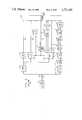
- FIG 1illustrates, in block diagram form, a voice analyzer in accordance with this invention
- FIG. 2illustrates, in block diagram form, a voice synthesizer in accordance with this invention
- FIG. 3illustrates a packet containing information for replicating speech during voiced regions
- FIG. 4illustrates a packet containing information for replicating speech during unvoiced regions utilizing noise excitation
- FIG. 5illustrates a packet containing information for replicating voice during unvoiced regions utilizing pulse excitation
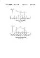
- FIG. 6illustrates the manner in which voice frame segmenter 141 of FIG. 1 overlaps speech frames with segments
- FIG. 7illustrates, in graph form, the interpolation performed by the synthesizer of FIG. 2 for the fundamental and harmonic frequencies
- FIG. 8illustrates, in graph form, the interpolation performed by the synthesizer of FIG. 2 for amplitudes of the fundamental and harmonic frequencies
- FIG. 9illustrates a digital signal processor implementation of FIGS. 1 and 2;
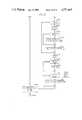
- FIGS. 10 through 13illustrate, in flowchart form, a program for controlling signal processor 903 of FIG. 9 to allow implementation of the analyzer circuit of FIG. 1;
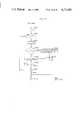
- FIGS. 14 through 19illustrate, in flowchart form, a program to control the execution of digital signal processor 903 of FIG. 9 to allow implementation of the synthesizer of FIG. 2;
- FIGS. 20, 21, and 22illustrate, in flowchart form, other program routines to control the execution of digital signal processor 903 of FIG. 9 to allow the implementation of high harmonic frequency calculator 211 of FIG. 2.
- FIGS. 1 and 2show an illustrative speech analyzer and speech synthesizer, respectively, which are the focus of this invention.
- Speech analyzer 100 of FIG. 1is responsive to analog speech signals received via path 120 to encode these signals at a low-bit rate for transmission to synthesizer 200 of FIG. 2 via channel 139.
- channel 139may be a communication transmission path or may be storage media so that voice synthesis may be provided for various applications requiring synthesized voice at a later point in time.
- Analyzer 100encodes the voice received via channel 120 utilizing three different encoding techniques. During voiced regions of speech, analyzer 100 encodes information that will allow synthesizer 200 to perform a sinusoidal modeling and reproduction of the speech.
- a regionis classified as voiced if a fundamental frequency is imparted to the air stream by the vocal cords.
- analyzer 100encodes information that allows the speech to be replicated in synthesizer 200 by driving a linear predictive coding, LPC, filter with appropriate excitation.
- the type of excitationis determined by analyzer 100 for each unvoiced frame.
- Multipulse excitationis encoded and transmitted to synthesizer 200 by analyzer 100 during unvoiced regions that contain plosive consonants and transitions between voiced and unvoiced speech regions which are, nevertheless, classified as unvoiced. If multipulse excitation is not encoded for an unvoiced frame, then analyzer 100 transmits to synthesizer 200 a signal indicating that white noise excitation is to be used to drive the LPC filter.
- Analyzer 100processes the digital samples received from analog-to-digital converter 101 in terms of frames, segmented by frame segmenter 102 and with each frame advantageously consisting of 180 samples.
- the determination of whether a frame is voiced or unvoicedis made in the following manner.
- LPC calculator 111is responsive to the digitized samples of a frame to produce LPC coefficients that model the human vocal tract and residual signal. The formation of these latter coefficients and energy may be performed according to the arrangement disclosed in U.S. Pat. No. 3,740,476, issued to B. S. Atal, June 19, 1973, and assigned to the same assignees as this application, or in other arrangements well known in the art.
- Pitch detector 109is responsive to the residual signal received via path 122 and the speech samples receive via path 121 from frame segmenter block 102 to determine whether the frame is voiced or unvoiced. If pitch detector 109 determines that a frame is voiced, then blocks 141 through 147 perform a sinusoidal encoding of the frame. However, if the decision is made that the frame is unvoiced, then noise/multipulse decision block 112 determines whether noise excitation or multipulse excitation is to be utilized by synthesizer 200 to excite the filter defined by the LPC coefficients that are also calculated by LPC calculator block 111. If noise excitation is to be used, then this fact is transmitted via parameter encoding block 113 to synthesizer 200. However, if multipulse excitation is to be used, block 110 determines a pulse train location and amplitudes and transmits this information via paths 128 and 129 to parameter encoding block 113 for subsequent transmission to synthesizer 200 of FIG. 2.
- FIG. 3a packet transmitted during the unvoiced frame utilizing white noise excitation is illustrated in FIG. 4
- FIG. 5a packet transmitted during an unvoiced frame utilizing multipulse excitation is illustrated in FIG. 5.
- noise/multipulse decision block 112determines that noise excitation is to be utilized, it indicates this fact by transmitting a signal via path 124 to parameter encoder 113.
- the latter encoderis responsive to this signal to form the packet illustrated in FIG. 4 utilizing the LPC coefficients from block 111 and the gain as calculated from the residue signal by block 115. More detail concerning the operation of analyzer 100 during unvoiced frames is described in the patent application of D. P. Prezas, et al., Case 6-1 "Voice Synthesis Utilizing Multi-Level Filter Excitation", Ser. No. 770,631, Filed Aug. 28, 1985, and assigned to the same assignees as this application.
- FIG. 3illustrates the information that is transmitted from analyzer 100 to synthesizer 200.
- the LPC coefficientsare generated by LPC calculator 111 and transmitted via path 123 to parameter encoder 113; and the indication of the fact that the frame is voiced is transmitted from pitch detector 109 via path 130.
- the fundamental frequency of the voiced regionwhich is transmitted as a pitch period via path 131 by pitch detector 109.
- Parameter encoder 113is responsive to the period to convert it to the fundamental frequency before transmission on channel 139.
- the total energy of speech within frame, eois calculated by energy calculator 103.
- the latter calculatorgenerates eo by taking the square root of the summation of the digital samples squared.
- the digital samplesare received from frame segmenter 102 via path 121, and energy calculator 103 transmits the resulting calculated energy via path 135 to parameter encoder 113.
- Each framesuch as frame A illustrated in FIG. 6, consists of advantageously 180 samples.
- Voice frame segmenter 141is responsive to the digital samples from analog-to-digital converter 101 to extract segments of data samples with each segment overlapping a frame as illustrated in FIG. 6 by segment A and frame A.
- a segmentmay advantageously comprise 256 samples.
- the purpose of overlapping the frames before performing the sinusoidal analysisis to provide more information at the endpoints of the frames.
- Down sampler 142is responsive to the output of voiced frame segmenter 141 to select every other sample of the 256 sample segment, resulting in a group of samples having advantageously 128 samples. The purpose of this down sampling is to reduce the complexity of the calculations which are performed by blocks 143 and 144.
- Hamming window block 143is responsive to data from block 142, s n , to perform the windowing operation as given by the following equation: ##EQU1##
- the purpose of the windowing operationis to eliminate disjointness at the end points of a frame and to improve spectral resolution.
- block 144After the windowing operation has been performed, block 144 first pads zeros to the resulting samples from block 143.
- this paddingresults in a new sequence of 256 data points as defined in the following equation:
- block 144performs the discrete Fourier transform, which is defined by the following equation: ##EQU2## where s h p is the nth point of the padded sequence s p .
- the evaluation of equation 4is done using fast Fourier transform method.
- block 144After performing the FFT calculations, block 144 then obtains the spectrum, S, by calculating the magnitude squared of each complex frequency data point resulting from the calculation performed in equation 4; and this operation is defined by the following equation:
- Harmonic peak locator 145is responsive to the pitch period calculated by pitch detector 109 and the spectrum calculated by block 144 to determine the peaks within the spectrum that correspond to the first five harmonics after the fundamental frequency. This searching is done by utilizing the theoretical harmonic frequency which is the harmonic number times the fundamental frequency as a starting point in the spectrum and then climbing the slope to the highest sample within a predefined distance from the theoretical harmonic.
- harmonic interpolator 146performs a second order interpolation around the harmonic peaks determined by harmonic peak locator 145. This adjusts the value determined for the harmonic so that it more closely represents the correct value.
- the following equationdefines this second order interpolation used for each harmonic: ##EQU3## where M is equal to 256.
- Harmonic calculator 147is responsive to the adjusted harmonic frequencies and the pitch to determine the offsets between the theoretical harmonics and the calculated harmonic peaks. These offsets are then transmitted to parameter encoder 113 for subsequent transmission to synthesizer 200.
- Synthesizer 200is illustrated in FIG. 2 and is responsive to the vocal tract model and excitation information or sinusoidal information received via channel 139 to produce a replica of the original analog speech that has been encoded by analyzer 100 of FIG. 1. If the received information specifies that the frame is voiced, blocks 211 through 214 perform the sinusoidal synthesis to recreate the original voiced frame information in accordance with equation 1 and this reconstructed speech is then transferred via selector 206 to digital-to-analog converter 208 which converts the received digital information to an analog signal.
- the encoded information receivedis designated as unvoiced, then either noise excitation or multipulse excitation is used to drive synthesis filter 207.
- the noise/multipulse, N/M, signal transmitted via path 227determines whether noise or multipulse excitation is utilized and also operates selector 205 to transmit the output of the designated generator 203 or 204 to synthesis filter 207.
- Synthesis filter 207utilizes the LPC coefficients in order to model the vocal tract.
- the unvoiced frameis the first frame of an unvoiced region, then the LPC coefficients from the subsequent voiced frame are obtained by path 225 and are utilized to initialize synthesis filter 207.
- channel decoder 201transmits the fundamental frequency (pitch) via path 221 and harmonic frequency offset information via path 222 to low harmonic frequency calculator 212 and to high harmonic frequency calculator 211.
- the speech frame energy, eo, and the LPC coefficientsare transmitted to harmonic amplitude calculator 213 via paths 220 and 216, respectively.
- the voiced/unvoiced, V/U, signalis transmitted to harmonic frequency calculators 211 and 212.
- the V/U signalbeing equal to a "1" indicates that the frame is voiced.
- Low harmonic frequency calculator 212is responsive to the V/U equaling a "1" to calculate the first five harmonic frequencies in response to the fundamental frequency and harmonic frequency offset information. The latter calculator then transfers the first five harmonic frequencies to blocks 213 and 214 via path 223.
- High harmonic frequency calculator 211is responsive to the fundamental frequency and the V/U signal to generate the remaining harmonic frequencies of the frame and to transmit these harmonic frequencies to blocks 213 and 214 via path 229.
- Harmonic amplitude calculator 213is responsive to the harmonic frequencies from calculators 212 and 211, the frame energy information received via path 220, and the LPC coefficients received via path 216 to calculate the amplitudes of the harmonic frequencies.
- Sinusoidal generator 214is responsive to the frequency information received from calculators 211 and 212 to determine the harmonic phase information and then use this phase information and the harmonic amplitudes received from calculator 213 to perform the calculations indicated by equation 1.
- channel decoder 201receives a noise excitation packet such as illustrated in FIG. 4, channel decoder 201 transmits a signal, via path 227, causing selector 205 to select the output of white noise generator 203 and a signal, via path 215, causing selector 206 to select the output of synthesis filter 207.
- channel decoder 201transmits the gain to white noise generator 203 via path 228. The gain is generated by gain calculator 115 of analyzer 100 as illustrated in FIG. 1.
- Synthesis filter 207is responsive to the LPC coefficients received from channel decoder 201 via path 216 and the output of white noise generator 203 received via selector 205 to produce digital samples of speech.
- channel decoder 201receives from channel 139 a pulse excitation packet, as illustrated in FIG. 5, the latter decoder transmits the locations and amplitudes of the received pulses to pulse generator 204 via path 210.
- channel decoder 201conditions selector 205 via path 227, to select the output of pulse generator 204 and transfer this output to synthesis filter 207.
- Synthesis filter 207 and digital-to-analog converter 208then reproduce the speech.
- Converter 208has a self-contained low-pass filter at the output of the converter. Further information concerning the operation of blocks 203, 204, and 207 can be found in the aforementioned patent application of D. P. Prezas, et al.
- Low harmonic frequency calculator 212is responsive to the fundamental frequency, Fr, received via path 221 to determine a subset of harmonic frequencies which advantageously is 5 by utilizing the harmonic offsets, ho i , received via path 222.
- the theoretical harmonic frequency, ts iis obtained by simply multiplying the order of the harmonic times the fundamental frequency. The following equation defines the ith harmonic frequency for each of the harmonics. ##EQU4## where fr is the frequency resolution between spectral sample points.
- Calculator 211is responsive to the fundamental frequency, Fr, to generate the harmonic frequencies, hf i , where i ⁇ 6 by using the following equation:
- calculator 211is responsive to the fundamental frequency to generate the harmonic frequencies greater than the 5th harmonic using the equation:
- variable acan be chosen to be 2Hz.
- the integer number n for the ith frequencyis found by minimizing the expression
- calculator 211is responsive to the fundamental frequency and the offsets for advantageously the first 5 harmonic frequencies to generate the harmonic frequencies greater than advantageously the 5th harmonic by adding the offsets to the theoretical harmonic frequencies for the remaining harmonics by grouping the remaining harmonics in groups of five and adding the offsets to those groups.
- the following equationdefines this embodiment for a group of harmonics indexed from mk 1 +1 through (m+1)k 1 :
- the permutationscan be a function of the variable m (the group index). Note that in general, the last group will not be complete if the number of harmonics is not a multiple of k 1 .
- the permutationscould be either randomly, deterministically, or heuristically defined for each speech frame using well known techniques.
- Calculators 211 and 212produce one value for the fundamental frequency and each of the harmonic frequencies. This value is assumed to be located in the center of a speech frame that is being synthesized. The remaining per-sample frequencies for each sample in the frame are obtained by linearly interpolating between the frequencies of adjacent voiced frames or predetermined boundary conditions for adjacent unvoiced frames. This interpolation is performed in sinusoidal generator 214 and is described in subsequent paragraphs.
- Harmonic amplitude calculator 213is responsive to the frequencies calculated by calculators 211 and 212, the LPC coefficients received via path 216, and the frame energy, eo, received via path 220 to calculate the harmonic amplitudes.
- the LPC reflection coefficients for each voiced framedefine an acoustic tube model representing the vocal tract during each frame.
- the relative harmonic amplitudescan be determined from this information. However, since the LPC coefficients are modeling the structure of the vocal tract they do not contain information with respect to the amount of energy at each of these harmonic frequencies. This information is determined by calculator 213 using the frame energy received via path 220. For each frame, calculator 213 calculates the harmonic amplitudes which, like the frequency calculations, assumes that this amplitude is located in the center of the frame. Linear interpolation is then used to determine the remaining amplitudes throughout the frame by using amplitude information from adjacent voiced frames or predetermined boundary conditions for adjacent unvoiced frames.
- amplitudescan be found by recognizing that the vocal tract can be described by an all-pole filter, ##EQU5## where ##EQU6##
- the coefficient a 0equals 1.
- the coefficients a m , 1 ⁇ m ⁇ 10, necessary to describe the all-pole filtercan be obtained from the reflection coefficients received via path 216 by using the recursive step-up procedure described in Markel, J. D., and Gray, Jr., A. H., Linear Prediction of Speech, Springer-Berlag, New York, N.Y., 1976.
- the filter described in equations 11 and 12is used to compute the amplitudes of the harmonic components for each frame in the following manner.
- the harmonic amplitudes to be computedbe designated as ha i , 0 ⁇ i ⁇ h where h is the number of harmonics.
- An unscaled harmonic contribution value, he i , 0 ⁇ i ⁇ h,can be obtained for each harmonic frequency, hf i , by ##EQU7## where sr is the sampling rate.
- the total unscaled energy of all harmonics, Ecan be obtained by ##EQU8##
- the ith scaled harmonic amplitude, ha ican be computed by ##EQU10## where eo is the transmitted speech frame energy calculated by analyzer 100.
- sinusoidal generator 214utilizes the information received from calculators 211, 212, and 213 to perform the calculations indicated by equation 1.
- calculators 211, 212, and 213provide to generator 214 a single frequency and amplitude for each harmonic in that frame.
- Generator 214performs the linear interpolation for both the frequencies and amplitudes and converts the frequency information to phase information so as to have phases and amplitudes for each sample point throughout the frame.
- FIG. 7illustrates 5 speech frames and the linear interpolation that is performed for the fundamental frequency which is also considered to be the 0th harmonic frequency.
- the voiced framecan have a preceding unvoiced frame and a subsequent voiced frame.
- the voiced framecan be surrounded by other voiced frames.
- the voiced framecan have a preceding voice frame and a subsequent unvoiced frame.
- frame cpoints 701 through 703, represent the first condition; and the frequency hf i c is assumed to be constant from the beginning of the frame which is defined by 701.
- iis equal to 0.
- the crefers to the fact that this is the c frame.
- Frame bwhich is after frame c and defined by points 703 through 705, represents the second case; and linear interpolation is performed between points 702 and 704 utilizing frequencies hf i c and hf i b which occur at points 702 and 704, respectively.
- the third conditionis represented by frame a which extends from points 705 through 707, and the frame following frame a is an unvoiced frame, points 707 to 708. In this situation the harmonic frequencies, hf i a , are constant to the end of frame a at point 707.
- FIG. 8illustrates the interpolation of amplitudes.
- the interpolationis identical to that performed with respect to the frequencies.
- the start of the frameis assumed to have 0 amplitude as illustrated at the point 801.
- the end pointsuch as point 807, is assumed to have 0 amplitude.
- the per-sample phases of the nth sample, where O n ,i is the per-sample phase of the ith harmonic,are defined by ##EQU11## where sr is the output sample rate. It is only necessary to know the per-sample frequencies, W n ,i, to solve for the phases and these per-sample frequencies are found by doing interpolation.
- the linear interpolation of frequencies for voiced frame with adjacent voiced framessuch as frame b of FIG. 7 is defined by ##EQU12## where h min is the minimum number of harmonics in either adjacent frame.
- the transition from an unvoiced to a voiced frame, such as frame c,is handled by determining the per-sample harmonic frequency by
- Equation 20is used to calculate the per-sample harmonic frequencies for harmonics greater than h min . If frame b has more harmonics than frame a, equation 21 is used to calculate the per-sample harmonics frequency for harmonics greater than h min .
- the per-sample harmonic amplitudes, A n ,i,can be determined from ha i in a similar manner as defined by the following equations for voiced frame b. ##EQU13## When a frame is the start of a voiced region such as at the beginning of frame c, the per-sample harmonics amplitude are determined by ##EQU14## where h is the number of harmonics in frame c. When a frame is the end of a voiced region such as frame a, the per-sample amplitudes are determined by ##EQU15## where h is number of harmonics in frame a.
- equations 24 and 25are used to calculate the harmonic amplitudes for the harmonics greater than h min . If frame b has more harmonics than frame a, equation 18 is used to calculate the harmonic amplitude for the harmonics greater than h min .
- FIGS. 10 and 11show the steps necessary to implement the frame segmenter 141 of FIG. 1.
- segmenter 141stores each sample into a circular buffer B.
- Blocks 1001 through 1005continue to store the sample into circular buffer B utilizing the i index.
- Decision block 1002determines when the end of circular buffer B has been reached by comparing i against N which defines the end of the buffer and also N is the number of points in the spectral analysis.
- Nis equal to 256
- Wis equal to 180.
- Decision block 1005counts the number of samples being stored in circular buffer B; and when advantageously 180 samples as defined by W have been stored, designating a frame, block 1006 is executed; otherwise 1007 is executed, and the steps illustrated in FIG. 10 simply wait for the next sample from block 101.
- blocks 1006 through 1106 of FIGS. 10 and 11transfer the information from circular buffer B to array C, and the information in array C then represents one of the segments illustrated in FIG. 6.
- Downsampler 142 and Hamming Window block 143are implemented by blocks 1107 through 1110 of FIG. 11.
- the downsampling performed by block 142is implemented by block 1108; and the Hamming windowing function, as defined by equation 2, is performed by block 1109.
- Decision block 1107 and connector block 1110control the performance of these operations for all of the data points stored in array C.
- Blocks 1201 through 1207 of FIG. 12implement the functions of FFT spectrum magnitude block 144.
- the zero padding, as defined by equation 3,is performed by blocks 1201 through 1203.
- the implementation of the fast Fourier transform on the resulting data points from blocks 1201 through 1203is performed by 1204 giving the same results as defined by equation 4.
- Blocks 1205 through 1207are used to obtain the spectrum defined by equation 5.
- Blocks 145, 146 and 147 of FIG. 1are implemented by the steps illustrated by blocks 1208 through 1314 of FIGS. 12 and 13.
- the pitch period received from pitch detector 109 via path 131 of FIG. 1is converted to the fundamental frequency, Fr, by block 1208.
- This conversionis performed by both harmonic peak locator 145 and harmonic calculator 147.
- decision block 1209passes control to blocks 1301 and 1302 which set the harmonic offsets equal to 0.
- decision block 1209passes control to blocks 1301 and 1302 which set the harmonic offsets equal to 0.
- decision block 1303 and connector block 1314control the calculation of the subset of harmonic offsets which advantageously may be for harmonics 1 through 5.
- Block 1304determines the initial estimate of where the harmonic presently being calculated will be found within the spectrum, S.
- Blocks 1305 through 1308search and find the location of the peak associated with the present harmonic being calculated. These latter blocks implement harmonic peak locator 145. After the peak has been located, block 1309 performs the harmonic interpolation functions of block 146.
- Harmonic calculator 147is implemented by blocks 1310 through 1313.
- the unscaled offset for the harmonic currently being calculatedis obtained by the execution of block 1310.
- the results of block 1310are scaled by 1311 so that an integer number is obtained.
- Decision block 1312checks to make certain that the offset is within a predefined range to prevent an erroneous harmonic peak having been located. If the calculated offset is greater than the predefined range, the offset is set equal to 0 by execution of block 1313. After all the harmonic offsets have been calculated, control is passed to parameter encoder 113 of FIG. 1.
- FIGS. 14 through 19detail the steps executed by processor 803 in implementing synthesizer 200 of FIG. 2.
- Harmonic frequency calculators 212 and 211 of FIG. 2are implemented by blocks 1418 through 1424 of FIG. 14.
- Block 1418initializes the parameters to be utilized in this operation.
- Blocks 1419 through 1420initially calculate each of the harmonic frequencies, hf k i , by multiplying the fundamental frequency, which is obtained as the transmitted pitch, times k+1.
- the scaled transmitted offsetsare added to the first five theoretical harmonic frequencies by blocks 1421 through 1424.
- the constants k 0 and k 1are set equal to "1" and "5", respectively, by block 1421.
- Harmonic amplitude calculator 213is implemented by processor 803 of FIG. 8 executing blocks 1401 through 1417 of FIGS. 14 and 15.
- Blocks 1401 through 1407implement the step-up procedure in order to convert the LPC reflection coefficients for the all-pole filter description of the vocal tract which is given in equation 11.
- Blocks 1408 through 1412calculate the unscaled harmonic energy for each harmonic as defined in equation 13.
- Blocks 1413 through 1415are used to calculate the total unscaled energy, E, as defined by equation 14.
- Blocks 1416 and 1417calculate the ith frame scaled harmonic amplitude, ha b i defined by equation 16.
- Blocks 1501 through 1521 and blocks 1601 through 1614 of FIGS. 15 through 18illustrate the operations which are performed by processor 803 in doing the interpolation for the frequency and amplitudes for each of the harmonics as illustrated in FIGS. 7 and 8. These operations are performed by the first part of the frame being processed by blocks 1501 through 1521 and the second part of the frame being processed by blocks 1601 through 1614. As illustrated in FIG. 7, the first half of frame c extends from point 701 to 702, and the second half of frame c extends from point 702 to 703. The operation performed by these blocks is to first determine whether the previous frame was voiced or unvoiced.
- Block 1501 of FIG. 15sets up the initial values.
- the frequenciesare set equal to the center frequency as illustrated in FIG. 7.
- each data pointis set equal to the linear approximation starting from zero at the beginning of the frame to the midpoint amplitude, as illustrated for frame c of FIG. 8.
- decision block 1503 of FIG. 16determines whether the previous frame had more or less harmonics than the present frame.
- the number of harmonicsis indicated by the variable, sh.
- hminis set equal to the least number of harmonic of either frame.
- blocks 1511 and 1512are executed. The latter blocks determine the initial point of the present frame by calculating the last point of the previous frame for both frequency and amplitude. After this operation has been performed for all harmonics, blocks 1513 through 1515 calculate each of the per-sample values for both the frequencies and the amplitudes for all of the harmonics as defined by equation 22 and equation 26, respectively.
- blocks 1516 through 1521are calculated to account for the fact that the present frame may have more harmonics than than the previous frame. If the present frame has more harmonics than the previous frame, decision block 1516 transfers control to blocks 1517. Where there are more harmonics in the present frame than the previous frames, blocks 1517 through 1521 are executed and their operation is identical to blocks 1504 through 1510, as previously described.
- blocks 1601 through 1614The calculation of the per-sample points for each harmonic for frequency and amplitudes for the second half of the frame is illustrated by blocks 1601 through 1614.
- the decisionis made by block 1601 whether the next frame is voiced or unvoiced. If the next frame is unvoiced, blocks 1603 through 1607 are executed. Note, that it is not necessary to determine initial values as was performed by blocks 1504 and 1507, since the initial point is the midpoint of the frame for both frequency and amplitudes. Blocks 1603 through 1607 perform similar functions to those performed by blocks 1508 through 1510. If the next frame is a voiced frame, then decision block 1602 and blocks 1604 or 1605 are executed. The execution of these blocks is similar to that previously described for blocks 1503, 1505, and 1506.
- Blocks 1608 through 1611are similar in operation to blocks 1513 through 1516 as previously described. Note, that it is not necessary to set up the initial conditions for the second half of the frame for the frequencies and amplitudes. Blocks 1612 through 1614 are similar in operation to blocks 1519 through 1521 as previously described.
- Blocks 1701 through 1707 of FIG. 19utilize the previously calculated frequency information to calculate the phase of the harmonics from the frequencies and then to perform the calculation defined by equation 1.
- Blocks 1702 and 1703determine the initial speech sample for the start of the frame. After this initial point has been determined, the remainder of speech samples for the frame are calculated by blocks 1704 through 1707. The output from these blocks is then transmitted to digital-to-analog converter 208.
- calculator 211reuses the transmitted harmonic offsets to vary the calculated theoretical harmonic frequencies for harmonics greater than 5 and is illustrated in FIG. 20.
- Blocks 2003 through 2005are used to group the harmonics above the 5th harmonic into groups of 5, and blocks 2006 and 2007 then add the corresponding transmitted harmonic offset to each of the theoretical harmonic frequencies in these groups.
- FIG. 21illustrates a second alternate embodiment of calculator 211 which differs from the embodiment shown in FIG. 20 in that the order of the offsets is randomly permuted for each group of harmonic frequencies above the first five harmonics by block 2100.
- Blocks 2101 through 2108 of FIG. 21perform similar functions to those of corresponding blocks of FIG. 20.
- a third alternate embodimentis illustrate in FIG. 22. That embodiment varies the harmonic frequencies from the theoretical harmonic frequencies transmitted to calculator 213 and generator 214 of FIG. 2 by performing the calculations illustrated in blocks 2203 and 2204 for each harmonic frequency under control of blocks 2202 and 2205.
Landscapes
- Engineering & Computer Science (AREA)
- Physics & Mathematics (AREA)
- Audiology, Speech & Language Pathology (AREA)
- Computational Linguistics (AREA)
- Signal Processing (AREA)
- Health & Medical Sciences (AREA)
- Human Computer Interaction (AREA)
- Acoustics & Sound (AREA)
- Multimedia (AREA)
- Spectroscopy & Molecular Physics (AREA)
- Compression, Expansion, Code Conversion, And Decoders (AREA)
- Electrophonic Musical Instruments (AREA)
- Devices For Supply Of Signal Current (AREA)
- Analogue/Digital Conversion (AREA)
- Transmission Systems Not Characterized By The Medium Used For Transmission (AREA)
Abstract
Description
s(n)=Σa.sub.i (n) sin [φ.sub.i (n)]. (1)
s.sup.p ={s.sub.0.sup.h s.sub.1.sup.h . . . s.sub.127.sup.h 0.sub.128 0.sub.129 . . . 0.sub.255 }. (3)S.sub.k =F.sub.k F.sub.k *, 0≦k≦255, (5)
hf.sub.i =iFr, 6≦i≦h, (7)
hf.sub.i =na, 6≦i≦h, (8)
(iFr-na).sup.2 (9)
hf.sub.j =jFr+ho.sub.j
j=mk.sub.1 +1, . . . (m+1)k.sub.1 (10)
W.sub.n.sup.ci, =hf.sub.i.sup.c, 0≦n≦89. (20)
W.sub.n.sup.ai, =hf.sub.i.sup.a, 90≦n≦179. (21)
Claims (24)
Priority Applications (9)
| Application Number | Priority Date | Filing Date | Title |
|---|---|---|---|
| US06/906,424US4771465A (en) | 1986-09-11 | 1986-09-11 | Digital speech sinusoidal vocoder with transmission of only subset of harmonics |
| CA000540959ACA1307344C (en) | 1986-09-11 | 1987-06-30 | Digital speech sinusoidal vocoder with transmission of only a subset ofharmonics |
| EP87305944AEP0259950B1 (en) | 1986-09-11 | 1987-07-06 | Digital speech sinusoidal vocoder with transmission of only a subset of harmonics |
| DE8787305944TDE3777028D1 (en) | 1986-09-11 | 1987-07-06 | DIGITAL SINUS VOCODER WITH TRANSMISSION OF ONLY A PART OF THE HARMONIOUS. |
| AT87305944TATE73251T1 (en) | 1986-09-11 | 1987-07-06 | DIGITAL SINE VOCODER WITH TRANSMISSION OF ONLY A PART OF THE HARMONICS. |
| AU75302/87AAU575515B2 (en) | 1986-09-11 | 1987-07-07 | Digital speech sinusoidal vocoder |
| JP62171340AJPH0833753B2 (en) | 1986-09-11 | 1987-07-10 | Human voice coding processing system |
| KR1019870007479AKR960002387B1 (en) | 1986-09-11 | 1987-07-11 | Voice processing system and voice processing method |
| SG1233/92ASG123392G (en) | 1986-09-11 | 1992-12-09 | Digital speech sinusoidal vocoder with transmission of only a subset of harmonics |
Applications Claiming Priority (1)
| Application Number | Priority Date | Filing Date | Title |
|---|---|---|---|
| US06/906,424US4771465A (en) | 1986-09-11 | 1986-09-11 | Digital speech sinusoidal vocoder with transmission of only subset of harmonics |
Publications (1)
| Publication Number | Publication Date |
|---|---|
| US4771465Atrue US4771465A (en) | 1988-09-13 |
Family
ID=25422427
Family Applications (1)
| Application Number | Title | Priority Date | Filing Date |
|---|---|---|---|
| US06/906,424Expired - LifetimeUS4771465A (en) | 1986-09-11 | 1986-09-11 | Digital speech sinusoidal vocoder with transmission of only subset of harmonics |
Country Status (9)
| Country | Link |
|---|---|
| US (1) | US4771465A (en) |
| EP (1) | EP0259950B1 (en) |
| JP (1) | JPH0833753B2 (en) |
| KR (1) | KR960002387B1 (en) |
| AT (1) | ATE73251T1 (en) |
| AU (1) | AU575515B2 (en) |
| CA (1) | CA1307344C (en) |
| DE (1) | DE3777028D1 (en) |
| SG (1) | SG123392G (en) |
Cited By (54)
| Publication number | Priority date | Publication date | Assignee | Title |
|---|---|---|---|---|
| US5023910A (en)* | 1988-04-08 | 1991-06-11 | At&T Bell Laboratories | Vector quantization in a harmonic speech coding arrangement |
| US5127054A (en)* | 1988-04-29 | 1992-06-30 | Motorola, Inc. | Speech quality improvement for voice coders and synthesizers |
| US5179626A (en)* | 1988-04-08 | 1993-01-12 | At&T Bell Laboratories | Harmonic speech coding arrangement where a set of parameters for a continuous magnitude spectrum is determined by a speech analyzer and the parameters are used by a synthesizer to determine a spectrum which is used to determine senusoids for synthesis |
| US5189701A (en)* | 1991-10-25 | 1993-02-23 | Micom Communications Corp. | Voice coder/decoder and methods of coding/decoding |
| US5231669A (en)* | 1988-07-18 | 1993-07-27 | International Business Machines Corporation | Low bit rate voice coding method and device |
| US5293448A (en)* | 1989-10-02 | 1994-03-08 | Nippon Telegraph And Telephone Corporation | Speech analysis-synthesis method and apparatus therefor |
| US5414796A (en)* | 1991-06-11 | 1995-05-09 | Qualcomm Incorporated | Variable rate vocoder |
| US5444816A (en)* | 1990-02-23 | 1995-08-22 | Universite De Sherbrooke | Dynamic codebook for efficient speech coding based on algebraic codes |
| US5448679A (en)* | 1992-12-30 | 1995-09-05 | International Business Machines Corporation | Method and system for speech data compression and regeneration |
| WO1996002050A1 (en)* | 1994-07-11 | 1996-01-25 | Voxware, Inc. | Harmonic adaptive speech coding method and system |
| US5596676A (en)* | 1992-06-01 | 1997-01-21 | Hughes Electronics | Mode-specific method and apparatus for encoding signals containing speech |
| US5651092A (en)* | 1993-05-21 | 1997-07-22 | Mitsubishi Denki Kabushiki Kaisha | Method and apparatus for speech encoding, speech decoding, and speech post processing |
| US5701392A (en)* | 1990-02-23 | 1997-12-23 | Universite De Sherbrooke | Depth-first algebraic-codebook search for fast coding of speech |
| US5742734A (en)* | 1994-08-10 | 1998-04-21 | Qualcomm Incorporated | Encoding rate selection in a variable rate vocoder |
| US5751901A (en)* | 1996-07-31 | 1998-05-12 | Qualcomm Incorporated | Method for searching an excitation codebook in a code excited linear prediction (CELP) coder |
| US5754976A (en)* | 1990-02-23 | 1998-05-19 | Universite De Sherbrooke | Algebraic codebook with signal-selected pulse amplitude/position combinations for fast coding of speech |
| US5774837A (en)* | 1995-09-13 | 1998-06-30 | Voxware, Inc. | Speech coding system and method using voicing probability determination |
| US5778337A (en)* | 1996-05-06 | 1998-07-07 | Advanced Micro Devices, Inc. | Dispersed impulse generator system and method for efficiently computing an excitation signal in a speech production model |
| US5794199A (en)* | 1996-01-29 | 1998-08-11 | Texas Instruments Incorporated | Method and system for improved discontinuous speech transmission |
| US5809455A (en)* | 1992-04-15 | 1998-09-15 | Sony Corporation | Method and device for discriminating voiced and unvoiced sounds |
| US5897615A (en)* | 1995-10-18 | 1999-04-27 | Nec Corporation | Speech packet transmission system |
| US5911128A (en)* | 1994-08-05 | 1999-06-08 | Dejaco; Andrew P. | Method and apparatus for performing speech frame encoding mode selection in a variable rate encoding system |
| US6029133A (en)* | 1997-09-15 | 2000-02-22 | Tritech Microelectronics, Ltd. | Pitch synchronized sinusoidal synthesizer |
| US6173265B1 (en)* | 1995-12-28 | 2001-01-09 | Olympus Optical Co., Ltd. | Voice recording and/or reproducing method and apparatus for reducing a deterioration of a voice signal due to a change over from one coding device to another coding device |
| US6230130B1 (en) | 1998-05-18 | 2001-05-08 | U.S. Philips Corporation | Scalable mixing for speech streaming |
| US20020007268A1 (en)* | 2000-06-20 | 2002-01-17 | Oomen Arnoldus Werner Johannes | Sinusoidal coding |
| US6453287B1 (en)* | 1999-02-04 | 2002-09-17 | Georgia-Tech Research Corporation | Apparatus and quality enhancement algorithm for mixed excitation linear predictive (MELP) and other speech coders |
| US20030088328A1 (en)* | 2001-11-02 | 2003-05-08 | Kosuke Nishio | Encoding device and decoding device |
| US20030108108A1 (en)* | 2001-11-15 | 2003-06-12 | Takashi Katayama | Decoder, decoding method, and program distribution medium therefor |
| US20030163318A1 (en)* | 2002-02-28 | 2003-08-28 | Nec Corporation | Compression/decompression technique for speech synthesis |
| US20030187635A1 (en)* | 2002-03-28 | 2003-10-02 | Ramabadran Tenkasi V. | Method for modeling speech harmonic magnitudes |
| KR100388388B1 (en)* | 1995-02-22 | 2003-11-01 | 디지탈 보이스 시스템즈, 인코퍼레이티드 | Method and apparatus for synthesizing speech using regerated phase information |
| US6680972B1 (en) | 1997-06-10 | 2004-01-20 | Coding Technologies Sweden Ab | Source coding enhancement using spectral-band replication |
| US6691084B2 (en) | 1998-12-21 | 2004-02-10 | Qualcomm Incorporated | Multiple mode variable rate speech coding |
| US20040083095A1 (en)* | 2002-10-23 | 2004-04-29 | James Ashley | Method and apparatus for coding a noise-suppressed audio signal |
| US20050065787A1 (en)* | 2003-09-23 | 2005-03-24 | Jacek Stachurski | Hybrid speech coding and system |
| US6959274B1 (en)* | 1999-09-22 | 2005-10-25 | Mindspeed Technologies, Inc. | Fixed rate speech compression system and method |
| US7483758B2 (en) | 2000-05-23 | 2009-01-27 | Coding Technologies Sweden Ab | Spectral translation/folding in the subband domain |
| US20090144062A1 (en)* | 2007-11-29 | 2009-06-04 | Motorola, Inc. | Method and Apparatus to Facilitate Provision and Use of an Energy Value to Determine a Spectral Envelope Shape for Out-of-Signal Bandwidth Content |
| US20090198498A1 (en)* | 2008-02-01 | 2009-08-06 | Motorola, Inc. | Method and Apparatus for Estimating High-Band Energy in a Bandwidth Extension System |
| US20090326950A1 (en)* | 2007-03-12 | 2009-12-31 | Fujitsu Limited | Voice waveform interpolating apparatus and method |
| US20100017202A1 (en)* | 2008-07-09 | 2010-01-21 | Samsung Electronics Co., Ltd | Method and apparatus for determining coding mode |
| US20100049342A1 (en)* | 2008-08-21 | 2010-02-25 | Motorola, Inc. | Method and Apparatus to Facilitate Determining Signal Bounding Frequencies |
| US20100198587A1 (en)* | 2009-02-04 | 2010-08-05 | Motorola, Inc. | Bandwidth Extension Method and Apparatus for a Modified Discrete Cosine Transform Audio Coder |
| US20110112844A1 (en)* | 2008-02-07 | 2011-05-12 | Motorola, Inc. | Method and apparatus for estimating high-band energy in a bandwidth extension system |
| CN103811011A (en)* | 2012-11-02 | 2014-05-21 | 富士通株式会社 | Audio sine wave detection method and device |
| US8798991B2 (en)* | 2007-12-18 | 2014-08-05 | Fujitsu Limited | Non-speech section detecting method and non-speech section detecting device |
| US8935156B2 (en) | 1999-01-27 | 2015-01-13 | Dolby International Ab | Enhancing performance of spectral band replication and related high frequency reconstruction coding |
| US20150081285A1 (en)* | 2013-09-16 | 2015-03-19 | Samsung Electronics Co., Ltd. | Speech signal processing apparatus and method for enhancing speech intelligibility |
| US9323878B2 (en)* | 2014-02-07 | 2016-04-26 | Freescale Semiconductor, Inc. | Method of optimizing the design of an electronic device with respect to electromagnetic emissions based on frequency spreading introduced by data post-processing, computer program product for carrying out the method and associated article of manufacture |
| US9323879B2 (en) | 2014-02-07 | 2016-04-26 | Freescale Semiconductor, Inc. | Method of optimizing the design of an electronic device with respect to electromagnetic emissions based on frequency spreading introduced by hardware, computer program product for carrying out the method and associated article of manufacture |
| RU2584462C2 (en)* | 2014-06-10 | 2016-05-20 | Федеральное государственное образовательное бюджетное учреждение высшего профессионального образования Московский технический университет связи и информатики (ФГОБУ ВПО МТУСИ) | Method of transmitting and receiving signals presented by parameters of stepped modulation decomposition, and device therefor |
| US9400861B2 (en) | 2014-02-07 | 2016-07-26 | Freescale Semiconductor, Inc. | Method of optimizing the design of an electronic device with respect to electromagnetic emissions based on frequency spreading introduced by software, computer program product for carrying out the method and associated article of manufacture |
| US9761238B2 (en)* | 2012-03-21 | 2017-09-12 | Samsung Electronics Co., Ltd. | Method and apparatus for encoding and decoding high frequency for bandwidth extension |
Families Citing this family (13)
| Publication number | Priority date | Publication date | Assignee | Title |
|---|---|---|---|---|
| US4797926A (en)* | 1986-09-11 | 1989-01-10 | American Telephone And Telegraph Company, At&T Bell Laboratories | Digital speech vocoder |
| JP2586043B2 (en)* | 1987-05-14 | 1997-02-26 | 日本電気株式会社 | Multi-pulse encoder |
| FI95085C (en)* | 1992-05-11 | 1995-12-11 | Nokia Mobile Phones Ltd | A method for digitally encoding a speech signal and a speech encoder for performing the method |
| IT1257431B (en)* | 1992-12-04 | 1996-01-16 | Sip | PROCEDURE AND DEVICE FOR THE QUANTIZATION OF EXCIT EARNINGS IN VOICE CODERS BASED ON SUMMARY ANALYSIS TECHNIQUES |
| WO1998005029A1 (en)* | 1996-07-30 | 1998-02-05 | British Telecommunications Public Limited Company | Speech coding |
| KR19980025793A (en)* | 1996-10-05 | 1998-07-15 | 구자홍 | Voice data correction method and device |
| TW429700B (en)* | 1997-02-26 | 2001-04-11 | Sony Corp | Information encoding method and apparatus, information decoding method and apparatus and information recording medium |
| DE69819460T2 (en)* | 1997-07-11 | 2004-08-26 | Koninklijke Philips Electronics N.V. | TRANSMITTER WITH IMPROVED VOICE ENCODER AND DECODER |
| CN1231050A (en)* | 1997-07-11 | 1999-10-06 | 皇家菲利浦电子有限公司 | Transmitter with improved harmonic vocoder |
| US6810409B1 (en) | 1998-06-02 | 2004-10-26 | British Telecommunications Public Limited Company | Communications network |
| DE60019268T2 (en)* | 1999-11-16 | 2006-02-02 | Koninklijke Philips Electronics N.V. | BROADBAND AUDIO TRANSMISSION SYSTEM |
| CN105408956B (en) | 2013-06-21 | 2020-03-27 | 弗朗霍夫应用科学研究促进协会 | Method for obtaining spectral coefficients of a replacement frame of an audio signal and related product |
| CN109741757B (en)* | 2019-01-29 | 2020-10-23 | 桂林理工大学南宁分校 | A method for real-time speech compression and decompression for NB-IoT |
Citations (3)
| Publication number | Priority date | Publication date | Assignee | Title |
|---|---|---|---|---|
| US4058676A (en)* | 1975-07-07 | 1977-11-15 | International Communication Sciences | Speech analysis and synthesis system |
| US4304965A (en)* | 1979-05-29 | 1981-12-08 | Texas Instruments Incorporated | Data converter for a speech synthesizer |
| US4720861A (en)* | 1985-12-24 | 1988-01-19 | Itt Defense Communications A Division Of Itt Corporation | Digital speech coding circuit |
Family Cites Families (7)
| Publication number | Priority date | Publication date | Assignee | Title |
|---|---|---|---|---|
| JPS5543554A (en)* | 1978-09-25 | 1980-03-27 | Nippon Musical Instruments Mfg | Electronic musical instrument |
| JPS56119194A (en)* | 1980-02-23 | 1981-09-18 | Sony Corp | Sound source device for electronic music instrument |
| JPS56125795A (en)* | 1980-03-05 | 1981-10-02 | Sony Corp | Sound source for electronic music instrument |
| US4513651A (en)* | 1983-07-25 | 1985-04-30 | Kawai Musical Instrument Mfg. Co., Ltd. | Generation of anharmonic overtones in a musical instrument by additive synthesis |
| US4701954A (en)* | 1984-03-16 | 1987-10-20 | American Telephone And Telegraph Company, At&T Bell Laboratories | Multipulse LPC speech processing arrangement |
| JPS6121000A (en)* | 1984-07-10 | 1986-01-29 | 日本電気株式会社 | Csm type voice synthesizer |
| JP2759646B2 (en)* | 1985-03-18 | 1998-05-28 | マサチユ−セツツ インステイテユ−ト オブ テクノロジ− | Sound waveform processing |
- 1986
- 1986-09-11USUS06/906,424patent/US4771465A/ennot_activeExpired - Lifetime
- 1987
- 1987-06-30CACA000540959Apatent/CA1307344C/ennot_activeExpired - Lifetime
- 1987-07-06EPEP87305944Apatent/EP0259950B1/ennot_activeExpired - Lifetime
- 1987-07-06ATAT87305944Tpatent/ATE73251T1/ennot_activeIP Right Cessation
- 1987-07-06DEDE8787305944Tpatent/DE3777028D1/ennot_activeExpired - Fee Related
- 1987-07-07AUAU75302/87Apatent/AU575515B2/ennot_activeCeased
- 1987-07-10JPJP62171340Apatent/JPH0833753B2/ennot_activeExpired - Lifetime
- 1987-07-11KRKR1019870007479Apatent/KR960002387B1/ennot_activeExpired - Fee Related
- 1992
- 1992-12-09SGSG1233/92Apatent/SG123392G/enunknown
Patent Citations (3)
| Publication number | Priority date | Publication date | Assignee | Title |
|---|---|---|---|---|
| US4058676A (en)* | 1975-07-07 | 1977-11-15 | International Communication Sciences | Speech analysis and synthesis system |
| US4304965A (en)* | 1979-05-29 | 1981-12-08 | Texas Instruments Incorporated | Data converter for a speech synthesizer |
| US4720861A (en)* | 1985-12-24 | 1988-01-19 | Itt Defense Communications A Division Of Itt Corporation | Digital speech coding circuit |
Non-Patent Citations (10)
| Title |
|---|
| "A Background for Sinusoid Based Representation of Voice Speech", Jorge S. Marques and Luis B. Almeida, ICASSP 1986, pp. 1233-1236. |
| "A Study on the Relationships between Stochastic and Harmonic Coding", Isabel M. Trancoso, Luis B. Almeida and Jose M. Tribolet, ICASSP 1986. pp. 1709-1712. |
| "Magnitude-Only Reconstruction Using a Sinusoidal Speech Model", R. J. McAulay and T. F. Quatieri, IEEE 1984, pp. 27.6.1-27.6.4. |
| "Mid-Rate Coding Based on a Sinusoidal Representation of Speech", Robert J. McAulay and Thomas F. Quartieri, ICASSP 85, vol. 3 of 4, pp. 944-948. |
| "Variable-Frequency Synthesis: An Improved Harmonic Coding Scheme", Luis B. Almeida and Fernando M. Silva, ICASSP 84, vol. 2 of 3, pp. 27.5.1-27.5.4. |
| A Background for Sinusoid Based Representation of Voice Speech , Jorge S. Marques and Luis B. Almeida, ICASSP 1986, pp. 1233 1236.* |
| A Study on the Relationships between Stochastic and Harmonic Coding , Isabel M. Trancoso, Luis B. Almeida and Jose M. Tribolet, ICASSP 1986. pp. 1709 1712.* |
| Magnitude Only Reconstruction Using a Sinusoidal Speech Model , R. J. McAulay and T. F. Quatieri, IEEE 1984, pp. 27.6.1 27.6.4.* |
| Mid Rate Coding Based on a Sinusoidal Representation of Speech , Robert J. McAulay and Thomas F. Quartieri, ICASSP 85, vol. 3 of 4, pp. 944 948.* |
| Variable Frequency Synthesis: An Improved Harmonic Coding Scheme , Luis B. Almeida and Fernando M. Silva, ICASSP 84, vol. 2 of 3, pp. 27.5.1 27.5.4.* |
Cited By (103)
| Publication number | Priority date | Publication date | Assignee | Title |
|---|---|---|---|---|
| US5179626A (en)* | 1988-04-08 | 1993-01-12 | At&T Bell Laboratories | Harmonic speech coding arrangement where a set of parameters for a continuous magnitude spectrum is determined by a speech analyzer and the parameters are used by a synthesizer to determine a spectrum which is used to determine senusoids for synthesis |
| US5023910A (en)* | 1988-04-08 | 1991-06-11 | At&T Bell Laboratories | Vector quantization in a harmonic speech coding arrangement |
| US5127054A (en)* | 1988-04-29 | 1992-06-30 | Motorola, Inc. | Speech quality improvement for voice coders and synthesizers |
| US5231669A (en)* | 1988-07-18 | 1993-07-27 | International Business Machines Corporation | Low bit rate voice coding method and device |
| US5293448A (en)* | 1989-10-02 | 1994-03-08 | Nippon Telegraph And Telephone Corporation | Speech analysis-synthesis method and apparatus therefor |
| US5699482A (en)* | 1990-02-23 | 1997-12-16 | Universite De Sherbrooke | Fast sparse-algebraic-codebook search for efficient speech coding |
| US5754976A (en)* | 1990-02-23 | 1998-05-19 | Universite De Sherbrooke | Algebraic codebook with signal-selected pulse amplitude/position combinations for fast coding of speech |
| US5444816A (en)* | 1990-02-23 | 1995-08-22 | Universite De Sherbrooke | Dynamic codebook for efficient speech coding based on algebraic codes |
| US5701392A (en)* | 1990-02-23 | 1997-12-23 | Universite De Sherbrooke | Depth-first algebraic-codebook search for fast coding of speech |
| US5414796A (en)* | 1991-06-11 | 1995-05-09 | Qualcomm Incorporated | Variable rate vocoder |
| US5657420A (en)* | 1991-06-11 | 1997-08-12 | Qualcomm Incorporated | Variable rate vocoder |
| US5189701A (en)* | 1991-10-25 | 1993-02-23 | Micom Communications Corp. | Voice coder/decoder and methods of coding/decoding |
| US5809455A (en)* | 1992-04-15 | 1998-09-15 | Sony Corporation | Method and device for discriminating voiced and unvoiced sounds |
| US5734789A (en)* | 1992-06-01 | 1998-03-31 | Hughes Electronics | Voiced, unvoiced or noise modes in a CELP vocoder |
| US5596676A (en)* | 1992-06-01 | 1997-01-21 | Hughes Electronics | Mode-specific method and apparatus for encoding signals containing speech |
| US5448679A (en)* | 1992-12-30 | 1995-09-05 | International Business Machines Corporation | Method and system for speech data compression and regeneration |
| US5651092A (en)* | 1993-05-21 | 1997-07-22 | Mitsubishi Denki Kabushiki Kaisha | Method and apparatus for speech encoding, speech decoding, and speech post processing |
| WO1996002050A1 (en)* | 1994-07-11 | 1996-01-25 | Voxware, Inc. | Harmonic adaptive speech coding method and system |
| US5787387A (en)* | 1994-07-11 | 1998-07-28 | Voxware, Inc. | Harmonic adaptive speech coding method and system |
| US6484138B2 (en) | 1994-08-05 | 2002-11-19 | Qualcomm, Incorporated | Method and apparatus for performing speech frame encoding mode selection in a variable rate encoding system |
| US5911128A (en)* | 1994-08-05 | 1999-06-08 | Dejaco; Andrew P. | Method and apparatus for performing speech frame encoding mode selection in a variable rate encoding system |
| US5742734A (en)* | 1994-08-10 | 1998-04-21 | Qualcomm Incorporated | Encoding rate selection in a variable rate vocoder |
| KR100388388B1 (en)* | 1995-02-22 | 2003-11-01 | 디지탈 보이스 시스템즈, 인코퍼레이티드 | Method and apparatus for synthesizing speech using regerated phase information |
| US5774837A (en)* | 1995-09-13 | 1998-06-30 | Voxware, Inc. | Speech coding system and method using voicing probability determination |
| US5890108A (en)* | 1995-09-13 | 1999-03-30 | Voxware, Inc. | Low bit-rate speech coding system and method using voicing probability determination |
| US5897615A (en)* | 1995-10-18 | 1999-04-27 | Nec Corporation | Speech packet transmission system |
| US6173265B1 (en)* | 1995-12-28 | 2001-01-09 | Olympus Optical Co., Ltd. | Voice recording and/or reproducing method and apparatus for reducing a deterioration of a voice signal due to a change over from one coding device to another coding device |
| US5794199A (en)* | 1996-01-29 | 1998-08-11 | Texas Instruments Incorporated | Method and system for improved discontinuous speech transmission |
| US6101466A (en)* | 1996-01-29 | 2000-08-08 | Texas Instruments Incorporated | Method and system for improved discontinuous speech transmission |
| US5978760A (en)* | 1996-01-29 | 1999-11-02 | Texas Instruments Incorporated | Method and system for improved discontinuous speech transmission |
| US5778337A (en)* | 1996-05-06 | 1998-07-07 | Advanced Micro Devices, Inc. | Dispersed impulse generator system and method for efficiently computing an excitation signal in a speech production model |
| US5751901A (en)* | 1996-07-31 | 1998-05-12 | Qualcomm Incorporated | Method for searching an excitation codebook in a code excited linear prediction (CELP) coder |
| US7328162B2 (en) | 1997-06-10 | 2008-02-05 | Coding Technologies Ab | Source coding enhancement using spectral-band replication |
| US20040078205A1 (en)* | 1997-06-10 | 2004-04-22 | Coding Technologies Sweden Ab | Source coding enhancement using spectral-band replication |
| US20040125878A1 (en)* | 1997-06-10 | 2004-07-01 | Coding Technologies Sweden Ab | Source coding enhancement using spectral-band replication |
| US20040078194A1 (en)* | 1997-06-10 | 2004-04-22 | Coding Technologies Sweden Ab | Source coding enhancement using spectral-band replication |
| US6680972B1 (en) | 1997-06-10 | 2004-01-20 | Coding Technologies Sweden Ab | Source coding enhancement using spectral-band replication |
| US7283955B2 (en) | 1997-06-10 | 2007-10-16 | Coding Technologies Ab | Source coding enhancement using spectral-band replication |
| US6925116B2 (en) | 1997-06-10 | 2005-08-02 | Coding Technologies Ab | Source coding enhancement using spectral-band replication |
| US6029133A (en)* | 1997-09-15 | 2000-02-22 | Tritech Microelectronics, Ltd. | Pitch synchronized sinusoidal synthesizer |
| US6230130B1 (en) | 1998-05-18 | 2001-05-08 | U.S. Philips Corporation | Scalable mixing for speech streaming |
| US7496505B2 (en) | 1998-12-21 | 2009-02-24 | Qualcomm Incorporated | Variable rate speech coding |
| US6691084B2 (en) | 1998-12-21 | 2004-02-10 | Qualcomm Incorporated | Multiple mode variable rate speech coding |
| US8935156B2 (en) | 1999-01-27 | 2015-01-13 | Dolby International Ab | Enhancing performance of spectral band replication and related high frequency reconstruction coding |
| US9245533B2 (en) | 1999-01-27 | 2016-01-26 | Dolby International Ab | Enhancing performance of spectral band replication and related high frequency reconstruction coding |
| US6453287B1 (en)* | 1999-02-04 | 2002-09-17 | Georgia-Tech Research Corporation | Apparatus and quality enhancement algorithm for mixed excitation linear predictive (MELP) and other speech coders |
| US6959274B1 (en)* | 1999-09-22 | 2005-10-25 | Mindspeed Technologies, Inc. | Fixed rate speech compression system and method |
| US20090043574A1 (en)* | 1999-09-22 | 2009-02-12 | Conexant Systems, Inc. | Speech coding system and method using bi-directional mirror-image predicted pulses |
| US10204628B2 (en) | 1999-09-22 | 2019-02-12 | Nytell Software LLC | Speech coding system and method using silence enhancement |
| US8620649B2 (en) | 1999-09-22 | 2013-12-31 | O'hearn Audio Llc | Speech coding system and method using bi-directional mirror-image predicted pulses |
| US9691403B1 (en) | 2000-05-23 | 2017-06-27 | Dolby International Ab | Spectral translation/folding in the subband domain |
| US20100211399A1 (en)* | 2000-05-23 | 2010-08-19 | Lars Liljeryd | Spectral Translation/Folding in the Subband Domain |
| US10699724B2 (en) | 2000-05-23 | 2020-06-30 | Dolby International Ab | Spectral translation/folding in the subband domain |
| US10311882B2 (en) | 2000-05-23 | 2019-06-04 | Dolby International Ab | Spectral translation/folding in the subband domain |
| US9786290B2 (en) | 2000-05-23 | 2017-10-10 | Dolby International Ab | Spectral translation/folding in the subband domain |
| US7483758B2 (en) | 2000-05-23 | 2009-01-27 | Coding Technologies Sweden Ab | Spectral translation/folding in the subband domain |
| US20090041111A1 (en)* | 2000-05-23 | 2009-02-12 | Coding Technologies Sweden Ab | spectral translation/folding in the subband domain |
| US9697841B2 (en) | 2000-05-23 | 2017-07-04 | Dolby International Ab | Spectral translation/folding in the subband domain |
| US9691399B1 (en) | 2000-05-23 | 2017-06-27 | Dolby International Ab | Spectral translation/folding in the subband domain |
| US9691401B1 (en) | 2000-05-23 | 2017-06-27 | Dolby International Ab | Spectral translation/folding in the subband domain |
| US9691400B1 (en) | 2000-05-23 | 2017-06-27 | Dolby International Ab | Spectral translation/folding in the subband domain |
| US9691402B1 (en) | 2000-05-23 | 2017-06-27 | Dolby International Ab | Spectral translation/folding in the subband domain |
| US9245534B2 (en) | 2000-05-23 | 2016-01-26 | Dolby International Ab | Spectral translation/folding in the subband domain |
| US10008213B2 (en) | 2000-05-23 | 2018-06-26 | Dolby International Ab | Spectral translation/folding in the subband domain |
| US7680552B2 (en) | 2000-05-23 | 2010-03-16 | Coding Technologies Sweden Ab | Spectral translation/folding in the subband domain |
| US8543232B2 (en) | 2000-05-23 | 2013-09-24 | Dolby International Ab | Spectral translation/folding in the subband domain |
| US8412365B2 (en) | 2000-05-23 | 2013-04-02 | Dolby International Ab | Spectral translation/folding in the subband domain |
| US7739106B2 (en)* | 2000-06-20 | 2010-06-15 | Koninklijke Philips Electronics N.V. | Sinusoidal coding including a phase jitter parameter |
| US20020007268A1 (en)* | 2000-06-20 | 2002-01-17 | Oomen Arnoldus Werner Johannes | Sinusoidal coding |
| US20030088328A1 (en)* | 2001-11-02 | 2003-05-08 | Kosuke Nishio | Encoding device and decoding device |
| US7283967B2 (en)* | 2001-11-02 | 2007-10-16 | Matsushita Electric Industrial Co., Ltd. | Encoding device decoding device |
| US20030108108A1 (en)* | 2001-11-15 | 2003-06-12 | Takashi Katayama | Decoder, decoding method, and program distribution medium therefor |
| US20030163318A1 (en)* | 2002-02-28 | 2003-08-28 | Nec Corporation | Compression/decompression technique for speech synthesis |
| US7027980B2 (en) | 2002-03-28 | 2006-04-11 | Motorola, Inc. | Method for modeling speech harmonic magnitudes |
| WO2003083833A1 (en)* | 2002-03-28 | 2003-10-09 | Motorola, Inc., A Corporation Of The State Of Delaware | Method for modeling speech harmonic magnitudes |
| US20030187635A1 (en)* | 2002-03-28 | 2003-10-02 | Ramabadran Tenkasi V. | Method for modeling speech harmonic magnitudes |
| US20040083095A1 (en)* | 2002-10-23 | 2004-04-29 | James Ashley | Method and apparatus for coding a noise-suppressed audio signal |
| US7343283B2 (en)* | 2002-10-23 | 2008-03-11 | Motorola, Inc. | Method and apparatus for coding a noise-suppressed audio signal |
| US20050065787A1 (en)* | 2003-09-23 | 2005-03-24 | Jacek Stachurski | Hybrid speech coding and system |
| US20090326950A1 (en)* | 2007-03-12 | 2009-12-31 | Fujitsu Limited | Voice waveform interpolating apparatus and method |
| US20090144062A1 (en)* | 2007-11-29 | 2009-06-04 | Motorola, Inc. | Method and Apparatus to Facilitate Provision and Use of an Energy Value to Determine a Spectral Envelope Shape for Out-of-Signal Bandwidth Content |
| US8688441B2 (en) | 2007-11-29 | 2014-04-01 | Motorola Mobility Llc | Method and apparatus to facilitate provision and use of an energy value to determine a spectral envelope shape for out-of-signal bandwidth content |
| US8798991B2 (en)* | 2007-12-18 | 2014-08-05 | Fujitsu Limited | Non-speech section detecting method and non-speech section detecting device |
| US20090198498A1 (en)* | 2008-02-01 | 2009-08-06 | Motorola, Inc. | Method and Apparatus for Estimating High-Band Energy in a Bandwidth Extension System |
| US8433582B2 (en) | 2008-02-01 | 2013-04-30 | Motorola Mobility Llc | Method and apparatus for estimating high-band energy in a bandwidth extension system |
| US8527283B2 (en) | 2008-02-07 | 2013-09-03 | Motorola Mobility Llc | Method and apparatus for estimating high-band energy in a bandwidth extension system |
| US20110112844A1 (en)* | 2008-02-07 | 2011-05-12 | Motorola, Inc. | Method and apparatus for estimating high-band energy in a bandwidth extension system |
| US9847090B2 (en) | 2008-07-09 | 2017-12-19 | Samsung Electronics Co., Ltd. | Method and apparatus for determining coding mode |
| US20100017202A1 (en)* | 2008-07-09 | 2010-01-21 | Samsung Electronics Co., Ltd | Method and apparatus for determining coding mode |
| US10360921B2 (en) | 2008-07-09 | 2019-07-23 | Samsung Electronics Co., Ltd. | Method and apparatus for determining coding mode |
| US8463412B2 (en) | 2008-08-21 | 2013-06-11 | Motorola Mobility Llc | Method and apparatus to facilitate determining signal bounding frequencies |
| US20100049342A1 (en)* | 2008-08-21 | 2010-02-25 | Motorola, Inc. | Method and Apparatus to Facilitate Determining Signal Bounding Frequencies |
| US20100198587A1 (en)* | 2009-02-04 | 2010-08-05 | Motorola, Inc. | Bandwidth Extension Method and Apparatus for a Modified Discrete Cosine Transform Audio Coder |
| US8463599B2 (en) | 2009-02-04 | 2013-06-11 | Motorola Mobility Llc | Bandwidth extension method and apparatus for a modified discrete cosine transform audio coder |
| US10339948B2 (en) | 2012-03-21 | 2019-07-02 | Samsung Electronics Co., Ltd. | Method and apparatus for encoding and decoding high frequency for bandwidth extension |
| US9761238B2 (en)* | 2012-03-21 | 2017-09-12 | Samsung Electronics Co., Ltd. | Method and apparatus for encoding and decoding high frequency for bandwidth extension |
| CN103811011A (en)* | 2012-11-02 | 2014-05-21 | 富士通株式会社 | Audio sine wave detection method and device |
| US9767829B2 (en)* | 2013-09-16 | 2017-09-19 | Samsung Electronics Co., Ltd. | Speech signal processing apparatus and method for enhancing speech intelligibility |
| US20150081285A1 (en)* | 2013-09-16 | 2015-03-19 | Samsung Electronics Co., Ltd. | Speech signal processing apparatus and method for enhancing speech intelligibility |
| US9323879B2 (en) | 2014-02-07 | 2016-04-26 | Freescale Semiconductor, Inc. | Method of optimizing the design of an electronic device with respect to electromagnetic emissions based on frequency spreading introduced by hardware, computer program product for carrying out the method and associated article of manufacture |
| US9400861B2 (en) | 2014-02-07 | 2016-07-26 | Freescale Semiconductor, Inc. | Method of optimizing the design of an electronic device with respect to electromagnetic emissions based on frequency spreading introduced by software, computer program product for carrying out the method and associated article of manufacture |
| US9323878B2 (en)* | 2014-02-07 | 2016-04-26 | Freescale Semiconductor, Inc. | Method of optimizing the design of an electronic device with respect to electromagnetic emissions based on frequency spreading introduced by data post-processing, computer program product for carrying out the method and associated article of manufacture |
| RU2584462C2 (en)* | 2014-06-10 | 2016-05-20 | Федеральное государственное образовательное бюджетное учреждение высшего профессионального образования Московский технический университет связи и информатики (ФГОБУ ВПО МТУСИ) | Method of transmitting and receiving signals presented by parameters of stepped modulation decomposition, and device therefor |
Also Published As
| Publication number | Publication date |
|---|---|
| AU575515B2 (en) | 1988-07-28 |
| KR960002387B1 (en) | 1996-02-16 |
| KR880004425A (en) | 1988-06-07 |
| DE3777028D1 (en) | 1992-04-09 |
| AU7530287A (en) | 1988-03-17 |
| JPS6370300A (en) | 1988-03-30 |
| EP0259950A1 (en) | 1988-03-16 |
| ATE73251T1 (en) | 1992-03-15 |
| SG123392G (en) | 1993-02-19 |
| EP0259950B1 (en) | 1992-03-04 |
| CA1307344C (en) | 1992-09-08 |
| JPH0833753B2 (en) | 1996-03-29 |
Similar Documents
| Publication | Publication Date | Title |
|---|---|---|
| US4771465A (en) | Digital speech sinusoidal vocoder with transmission of only subset of harmonics | |
| US4797926A (en) | Digital speech vocoder | |
| US5384891A (en) | Vector quantizing apparatus and speech analysis-synthesis system using the apparatus | |
| EP0337636B1 (en) | Harmonic speech coding arrangement | |
| US5093863A (en) | Fast pitch tracking process for LTP-based speech coders | |
| US5794182A (en) | Linear predictive speech encoding systems with efficient combination pitch coefficients computation | |
| EP0336658B1 (en) | Vector quantization in a harmonic speech coding arrangement | |
| US5787387A (en) | Harmonic adaptive speech coding method and system | |
| RU2233010C2 (en) | Method and device for coding and decoding voice signals | |
| US6526376B1 (en) | Split band linear prediction vocoder with pitch extraction | |
| US5067158A (en) | Linear predictive residual representation via non-iterative spectral reconstruction | |
| EP0266620B1 (en) | Method of and device for speech signal coding and decoding by parameter extraction and vector quantization techniques | |
| US4821324A (en) | Low bit-rate pattern encoding and decoding capable of reducing an information transmission rate | |
| US6119082A (en) | Speech coding system and method including harmonic generator having an adaptive phase off-setter | |
| US4912764A (en) | Digital speech coder with different excitation types | |
| US4736428A (en) | Multi-pulse excited linear predictive speech coder | |
| US4945565A (en) | Low bit-rate pattern encoding and decoding with a reduced number of excitation pulses | |
| US4890328A (en) | Voice synthesis utilizing multi-level filter excitation | |
| AU5549090A (en) | Excitation pulse positioning method in a linear predictive speech coder | |
| US4969193A (en) | Method and apparatus for generating a signal transformation and the use thereof in signal processing | |
| US6026357A (en) | First formant location determination and removal from speech correlation information for pitch detection | |
| US5696874A (en) | Multipulse processing with freedom given to multipulse positions of a speech signal | |
| US5657419A (en) | Method for processing speech signal in speech processing system | |
| US6115685A (en) | Phase detection apparatus and method, and audio coding apparatus and method | |
| EP0534442A2 (en) | Code-book driven vocoder device with voice source generator |
Legal Events
| Date | Code | Title | Description |
|---|---|---|---|
| AS | Assignment | Owner name:BELL TELEPHONE LABORATORIES, INCORPORATED, 600 MOU Free format text:ASSIGNMENT OF ASSIGNORS INTEREST.;ASSIGNORS:BRONSON, EDWARD C.;HARTWELL, WALTER T.;JACOBS, THOMAS E.;AND OTHERS;REEL/FRAME:004632/0651;SIGNING DATES FROM 19860911 TO 19861002 Owner name:AMERICAN TELEPHONE AND TELEGRAPH COMPANY, 550 MADI Free format text:ASSIGNMENT OF ASSIGNORS INTEREST.;ASSIGNORS:BRONSON, EDWARD C.;HARTWELL, WALTER T.;JACOBS, THOMAS E.;AND OTHERS;REEL/FRAME:004632/0651;SIGNING DATES FROM 19860911 TO 19861002 Owner name:BELL TELEPHONE LABORATORIES, INCORPORATED,NEW JERS Free format text:ASSIGNMENT OF ASSIGNORS INTEREST;ASSIGNORS:BRONSON, EDWARD C.;HARTWELL, WALTER T.;JACOBS, THOMAS E.;AND OTHERS;SIGNING DATES FROM 19860911 TO 19861002;REEL/FRAME:004632/0651 Owner name:AMERICAN TELEPHONE AND TELEGRAPH COMPANY,NEW YORK Free format text:ASSIGNMENT OF ASSIGNORS INTEREST;ASSIGNORS:BRONSON, EDWARD C.;HARTWELL, WALTER T.;JACOBS, THOMAS E.;AND OTHERS;SIGNING DATES FROM 19860911 TO 19861002;REEL/FRAME:004632/0651 | |
| STCF | Information on status: patent grant | Free format text:PATENTED CASE | |
| FEPP | Fee payment procedure | Free format text:PAYOR NUMBER ASSIGNED (ORIGINAL EVENT CODE: ASPN); ENTITY STATUS OF PATENT OWNER: LARGE ENTITY | |
| FPAY | Fee payment | Year of fee payment:4 | |
| CC | Certificate of correction | ||
| FEPP | Fee payment procedure | Free format text:PAYER NUMBER DE-ASSIGNED (ORIGINAL EVENT CODE: RMPN); ENTITY STATUS OF PATENT OWNER: LARGE ENTITY Free format text:PAYOR NUMBER ASSIGNED (ORIGINAL EVENT CODE: ASPN); ENTITY STATUS OF PATENT OWNER: LARGE ENTITY | |
| FPAY | Fee payment | Year of fee payment:8 | |
| FEPP | Fee payment procedure | Free format text:PAYER NUMBER DE-ASSIGNED (ORIGINAL EVENT CODE: RMPN); ENTITY STATUS OF PATENT OWNER: LARGE ENTITY Free format text:PAYOR NUMBER ASSIGNED (ORIGINAL EVENT CODE: ASPN); ENTITY STATUS OF PATENT OWNER: LARGE ENTITY | |
| FPAY | Fee payment | Year of fee payment:12 |