US4769646A - Antenna system and dual-fed lenses producing characteristically different beams - Google Patents
Antenna system and dual-fed lenses producing characteristically different beamsDownload PDFInfo
- Publication number
- US4769646A US4769646AUS06/584,273US58427384AUS4769646AUS 4769646 AUS4769646 AUS 4769646AUS 58427384 AUS58427384 AUS 58427384AUS 4769646 AUS4769646 AUS 4769646A
- Authority
- US
- United States
- Prior art keywords
- lens
- radar
- dielectric
- antenna
- feed means
- Prior art date
- Legal status (The legal status is an assumption and is not a legal conclusion. Google has not performed a legal analysis and makes no representation as to the accuracy of the status listed.)
- Expired - Fee Related
Links
Images


Classifications
- H—ELECTRICITY
- H01—ELECTRIC ELEMENTS
- H01Q—ANTENNAS, i.e. RADIO AERIALS
- H01Q25/00—Antennas or antenna systems providing at least two radiating patterns
- H01Q25/002—Antennas or antenna systems providing at least two radiating patterns providing at least two patterns of different beamwidth; Variable beamwidth antennas
- H—ELECTRICITY
- H01—ELECTRIC ELEMENTS
- H01Q—ANTENNAS, i.e. RADIO AERIALS
- H01Q19/00—Combinations of primary active antenna elements and units with secondary devices, e.g. with quasi-optical devices, for giving the antenna a desired directional characteristic
- H01Q19/06—Combinations of primary active antenna elements and units with secondary devices, e.g. with quasi-optical devices, for giving the antenna a desired directional characteristic using refracting or diffracting devices, e.g. lens
Definitions
- This inventionis directed toward the art and technology of radar antenna systems and more particularly toward the use of off-axis and multiple feeds not precisely located at the radar antenna focal point.
- Radar systems of the prior arttypically position a single feed at the antenna focal point. Such antennas further are designed to optimize beam collimation and focusing with respect to the focal point. This generally limits the antennas of the prior art to a single antenna feed, and makes them generally unsuited for multimode applications.
- the inventionis directed toward a multimode radar antenna arrangement in which the feeds are removed from the focal point of the antenna.
- the passive antenna apertureis illuminated by several beams of microwave energy, which can accomplish independent functions using a single antenna aperture, and thus enhance the operational capabilities of the antenna system as a whole.
- one of the beamscan be employed in a broad beam search mode to seek out potential target signals; another beam, much narrower in beamwidth, can then be employed to track an acquired target.
- the invented antenna arrangementestablishes a large focal region--as opposed to a mere focal "point"--which can be employed to position several spaced feed structures.
- the designis carried out by minimizing off-axis optical aberrations throughout the required angular field and limiting total aberration to less than that produced by diffraction for the size and shape of the preferred antenna employed in the system.
- the designis made compact with no sacrifice in performance by including a significant "shared" region of the antenna aperture which can be illuminated by more than one of the multiple feeds. However, the independent nature of each of the output beams is maintained without regard to whether this shared region is illuminated by feeds other than that associated with the beam.
- FIG. 1shows a schematic antenna including a characteristic focal point, and a focal region within which the feeds of the invention herein can effectively be positioned;
- FIG. 2shows a preferred lens embodiment of the invention with two feeds acting as sources effective for producing a corresponding pair of antenna beams;
- FIG. 3shows a preferred version of the invention in which a pair of beams are produced, one of them being formed for example in the shape of a fan beam to search for targets, and the other acting as a pencil beam to track the target once acquired;
- FIG. 4shows a multiple lens version of the antenna including fan and pencil beam feeds cooperating respectively with the secondary and primary lens of the arrangement;
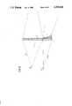
- FIG. 5shows the scheme of the antenna aperture based upon the version of the invention indicated in FIG. 4, which is divided into regions corresponding to the primary and secondary beams and a region of beam overlap;
- FIGS. 6A and 6Brespectively show two views of the preferred antenna arrangement including the placement of the antenna feeds, the first view being from the side, and the second from below;
- FIG. 7indicates a version of the invention in which the antenna lens is monolithically constructed, thereby combining the functions of the primary and the secondary lens in a single lens;
- FIG. 8shows a version of the invention based upon the embodiment shown in FIG. 4, in which however a portion of the primary lens is stepped according to the nature of a Fresnel lens.
- FIG. 1illustrates a significant difference between the prior art and the invention herein.
- FIG. 1illustrates a significant difference between the prior art and the invention herein.
- FIG. 1illustrates a significant difference between the prior art and the invention herein.
- FIG. 1illustrates a significant difference between the prior art and the invention herein.
- FIG. 1illustrates a significant difference between the prior art and the invention herein.
- FIG. 1illustrates a significant difference between the prior art and the invention herein.
- FIG. 1illustrates a significant difference between the prior art and the invention herein.
- FIG. 1illustrates a significant difference between the prior art and the invention herein.
- a focal region 17'is established which has dimensions permitting the positioning of several antenna feed structures in the proximity of the focal point 17, with substantially no sacrifice in beam quality.
- FIG. 2shows two feed structures, respectively 23 and 23', both positioned within the focal area 17'. These are effective for producing corresponding antenna illumination beams 27(1) and 27(2).
- the beams 27pass through the antenna 13 in this case, as the antenna of the preferred embodiment is a lens-type antenna, and are reformed by the antenna into output beams 29(1) and 29(2) respectively.
- FIG. 3shows a preferred version of the antenna arrangement in which the antenna produces two beams 29(2) and 29(1) including respectively a fan beam relatively narrow in azimuth but wide in elevation for searching out targets, and a relatively narrow symmetric pencil beam effective for tracking targets which have been acquired by the search effort of the fan beam.
- the fan beamitself is one of a category of wide beams which can be formed according to specific design.
- a preferred embodiment of the inventionemploys an antenna diameter exceeding several dozen wavelengths.
- the inventionis applicable to millimeter and submillimeter wavelength systems, for example.
- Significantly smaller diameters of the antenna 13derogate the intended focusing and collimating effects of the antenna.
- FIG. 4is a preferred version of the invention.
- the versionemploys primary and secondary lens, respectively 13' and 13", to perform the antenna function.
- Two feed structures 23 and 23'are employed in conjunction with the respective lens.
- the beam 27(1) from the first feed structure 23passes through the primary lens 13' which causes the output pencil beam 29(1) to be collimated.
- the beam 27(2) from the second feed structure 23'also passes through the primary lens 13' and is thus also collimated; however, a portion thereof then passes through the secondary lens 13" which is effective for broadening the beam into a divergent fan beam pattern of microwave radiation. Nonetheless, the entire fan beam does not pass through the secondary lens. A portion of it remains collimated and passes by the secondary lens 13" in unimpeded intensity.
- the antenna aperture or surfacecan therefore be said to be divided into three primary regions, as indicated in FIG. 5.
- the view shown in the Figureis from a frontal direction toward the antenna 13 itself.
- a major portion 71 of the surface of the antennais dedicated to the projection of the pencil beam.
- this portion 71 of the antenna 13effectively collimates the radiation produced from the first feed structure 23.
- the lower portion 72 of the antenna surfaceis devoted to forming the fan beam for example, which is derived from the second feed structure 23'. After passing through this portion of the antenna, the beam begins to diverge toward the target region.
- the secondary lens 13"preferably does not extend into the shared portion 74 of the antenna surface. This reduces losses in the collimated portion of the output beams.
- FIGS. 6A and 6Bshow the relative disposition of feeds to the antenna of the invention herein according to FIG. 4.
- FIG. 6Ashows a side view of the arrangement of primary and secondary feeds, respectively 23 and 23'.
- FIG. 6Bshows a corresponding bottom view thereof.
- the feeds 23 and 23'are suitably supported and arranged in a support structure including a source of microwave power and suitable circuitry (not shown) for controlling the timing and level of microwave power supplied through the respective feeds.
- the microwave poweris generated in a linearly polarized form and may for example according to a preferred version of the invention be converted to circularly polarized radiation. This is accomplished for example by positioning circular polarizers at the outputs of the respective feeds prior to its reaching the antenna for collimation.
- the beam from the second feed structure 23'is compressed by a cylindrical lens 77 as indicated in FIG. 6B.
- the beam initially departs from the feedit is generally rotationally symmetric about the axis of its direction of propagation toward the lower and shared regions of illumination 72 and 74 indicated in FIG. 5.
- the lower and shared regions of the antenna aperture toward which the fan beam is directedare not circular in shape and accordingly do not conform to the cross section of a rotationally symmetric beam.
- An incident beam having a perpendicular cross section more in the nature of an ellipsewould conform to the shape of the region to a significantly greater extent.
- a cylindrical lens 77 at the output of the second feed 23' disposed to compress the output beam in altitude and leaving it generally unaffected in azimuthis effective in conforming the cross section of the beam to the shape of the antenna aperture to which it corresponds, especially since the secondary lens 13" of the antenna arrangement itself is preferably cylindrical in nature.
- the antenna lensis capable of establishment in several pieces separately assemblable as indicated in FIG. 4, or in a single manufactured piece as suggested in FIG. 7. According to this version of the invention, the antenna lens is molded, machined, or otherwise fabricated, as a single, monolithic piece.
- FIG. 8shows a stepped version of the primary lens 13' in the form of a Fresnel lens, which provides for a more compact lens construction, reduces the weight of the entire assembly and reduces absorption losses in the microwave radiation passing through the lens.
- a preferred material for this embodiment of the antenna lensis a dielectric such as alumina or a similar ceramic, glass or polymer such as a cross-linked polystyrene, such as Rexolite.
- a dielectricsuch as alumina or a similar ceramic, glass or polymer such as a cross-linked polystyrene, such as Rexolite.
- the shape of the primary lens 13'varies according to the refractive index of the material employed to make the arrangement.
- the selected material to make the lensis a cross-linked polystyrene
- the input side of the primary lensis preferably flat and the output side is an elliptical conic section of revolution whose axis of symmetry coincides with the optical axis.
- the input side of the primary lensis preferably spherical and the output side is an elliptical conic section of revolution whose eccentricity is lower than that required for the polystyrene lens.
- the output side of the secondary lens 13"has a selected shape effective for establishing a desired distribution of intensity versus elevation angle.
- the desired distributionis the cosecant of theta squared times the square root of the cosine of theta, where theta is the elevation angle.
- the angle thetais the angular deviation from the line of sight to the target region.
- the cross-sectional shape of the output side of the secondary lensis generally not a simple conic section and it varies according to the material of which the lens is constituted.
- the surface of the secondary lens 13" closest to the primary lens 13'is preferably flat and perpendicular to the output beam from the primary lens 13'.
- a slight deviation from the perpendicularmay be taken, however, in mounting the secondary lens 13" directly on the bottom portion of the primary lens 13', as for example suggested in FIG. 8.
- the contour of the curved surface of the secondary lensis preferably slightly different than when the flat surface is perpendicularly oriented, in order to maintain the desired distribution of intensity versus elevation angle.
Landscapes
- Aerials With Secondary Devices (AREA)
- Radar Systems Or Details Thereof (AREA)
Abstract
Description
Claims (5)
Priority Applications (5)
| Application Number | Priority Date | Filing Date | Title |
|---|---|---|---|
| US06/584,273US4769646A (en) | 1984-02-27 | 1984-02-27 | Antenna system and dual-fed lenses producing characteristically different beams |
| CA000473536ACA1240773A (en) | 1984-02-27 | 1985-02-04 | Wide angle multi-mode antenna |
| GB08503703AGB2154804B (en) | 1984-02-27 | 1985-02-13 | Wide angle multi-mode antenna |
| DE19853505583DE3505583A1 (en) | 1984-02-27 | 1985-02-18 | RADAR ANTENNA ARRANGEMENT AND METHOD FOR MAKING SAME |
| JP60035445AJPS60204103A (en) | 1984-02-27 | 1985-02-26 | Radar antenna unit and method of constructing same |
Applications Claiming Priority (1)
| Application Number | Priority Date | Filing Date | Title |
|---|---|---|---|
| US06/584,273US4769646A (en) | 1984-02-27 | 1984-02-27 | Antenna system and dual-fed lenses producing characteristically different beams |
Publications (1)
| Publication Number | Publication Date |
|---|---|
| US4769646Atrue US4769646A (en) | 1988-09-06 |
Family
ID=24336644
Family Applications (1)
| Application Number | Title | Priority Date | Filing Date |
|---|---|---|---|
| US06/584,273Expired - Fee RelatedUS4769646A (en) | 1984-02-27 | 1984-02-27 | Antenna system and dual-fed lenses producing characteristically different beams |
Country Status (5)
| Country | Link |
|---|---|
| US (1) | US4769646A (en) |
| JP (1) | JPS60204103A (en) |
| CA (1) | CA1240773A (en) |
| DE (1) | DE3505583A1 (en) |
| GB (1) | GB2154804B (en) |
Cited By (25)
| Publication number | Priority date | Publication date | Assignee | Title |
|---|---|---|---|---|
| US4872019A (en)* | 1986-12-09 | 1989-10-03 | Her Majesty The Queen In Right Of Canada As Represented By The Minister Of National Defence | Radome-lens EHF antenna development |
| US5154973A (en)* | 1989-12-07 | 1992-10-13 | Murata Manufacturing Co., Ltd. | Composite material for dielectric lens antennas |
| US5175562A (en)* | 1989-06-23 | 1992-12-29 | Northeastern University | High aperture-efficient, wide-angle scanning offset reflector antenna |
| US5606334A (en)* | 1995-03-27 | 1997-02-25 | Amarillas; Sal G. | Integrated antenna for satellite and terrestrial broadcast reception |
| DE19626344A1 (en)* | 1996-03-15 | 1997-09-18 | Bosch Gmbh Robert | Bundling lens for vehicle sensor |
| DE19741081C1 (en)* | 1997-09-18 | 1999-03-18 | Bosch Gmbh Robert | Method of making an antenna lens |
| WO2000011751A1 (en)* | 1998-08-21 | 2000-03-02 | Raytheon Company | Improved lens system for antenna system |
| US6160519A (en)* | 1998-08-21 | 2000-12-12 | Raytheon Company | Two-dimensionally steered antenna system |
| WO2001026183A1 (en)* | 1999-10-06 | 2001-04-12 | Robert Bosch Gmbh | Asymmetrical multi-beam radar sensor |
| US6266029B1 (en) | 1998-12-22 | 2001-07-24 | Datron/Transco Inc. | Luneberg lens antenna with multiple gimbaled RF feeds |
| US6275184B1 (en) | 1999-11-30 | 2001-08-14 | Raytheon Company | Multi-level system and method for steering an antenna |
| US6281852B1 (en)* | 1995-03-27 | 2001-08-28 | Sal Amarillas | Integrated antenna for satellite and terrestrial broadcast reception |
| US6441793B1 (en)* | 2000-03-16 | 2002-08-27 | Austin Information Systems, Inc. | Method and apparatus for wireless communications and sensing utilizing a non-collimating lens |
| WO2005034291A1 (en)* | 2003-10-03 | 2005-04-14 | Murata Manufacturing Co., Ltd. | Dielectric lens, dielectric lens device, design method for dielectric lens, production method for dielectric lens and transmission/reception device |
| EP1624317A1 (en)* | 2004-08-05 | 2006-02-08 | Robert Bosch Gmbh | Radar sensor for motor vehicles with antenna sidelobe pointing at the road surface |
| EP1478942B1 (en)* | 2002-02-22 | 2006-06-28 | Robert Bosch Gmbh | Radar sensor for motor vehicles with antenna sidelobe pointing at the road surface |
| US20060267830A1 (en)* | 2005-02-10 | 2006-11-30 | O'boyle Michael E | Automotive radar system with guard beam |
| US20070290805A1 (en)* | 2006-06-09 | 2007-12-20 | Nec Corporation | Wireless communication system and wireless communication method |
| US20090281466A1 (en)* | 2002-01-29 | 2009-11-12 | Oregon Health & Science University | Device for rehabilitation of individuals experiencing loss of skeletal joint motor control |
| US20100231436A1 (en)* | 2007-08-02 | 2010-09-16 | Thomas Focke | Radar sensor for motor vehicles |
| US20100271278A1 (en)* | 2007-12-04 | 2010-10-28 | Thomas Binzer | Bistatic array antenna and method |
| US20120262331A1 (en)* | 2011-04-18 | 2012-10-18 | Klaus Kienzle | Filling level measuring device antenna cover |
| EP3096400A1 (en)* | 2015-05-19 | 2016-11-23 | Panasonic Intellectual Property Management Co., Ltd. | Antenna device, wireless communication apparatus, and radar apparatus |
| US20170331183A1 (en)* | 2014-12-11 | 2017-11-16 | Vega Grieshaber Kg | Antenna cover, use of an antenna cover, adapter for connecting two antenna covers and method for producing a lens-shaped antenna cover |
| WO2018140837A1 (en)* | 2017-01-27 | 2018-08-02 | Cohere Technologies | Variable beamwidth multiband antenna |
Families Citing this family (3)
| Publication number | Priority date | Publication date | Assignee | Title |
|---|---|---|---|---|
| EP2760082A1 (en)* | 2013-01-28 | 2014-07-30 | BAE Systems PLC | Directional multi-band antenna |
| US9761941B2 (en) | 2013-01-28 | 2017-09-12 | Bae Systems Plc | Directional multiband antenna |
| GB2556018A (en)* | 2016-07-01 | 2018-05-23 | Cambridge Communication Systems Ltd | An antenna for a communications system |
Citations (16)
| Publication number | Priority date | Publication date | Assignee | Title |
|---|---|---|---|---|
| US2530580A (en)* | 1946-10-30 | 1950-11-21 | Rca Corp | Multichannel signaling system |
| US2599864A (en)* | 1945-06-20 | 1952-06-10 | Robertson-Shersby-Ha Rob Bruce | Wave front modifying wave guide system |
| US2975419A (en)* | 1959-10-13 | 1961-03-14 | Newell H Brown | Microwave antenna reflector system for scanning by displacement of focal image |
| US3146451A (en)* | 1956-10-29 | 1964-08-25 | Lab For Electronics Inc | Dielectric lens giving perfect focal points at selected distance off-axis |
| US3170158A (en)* | 1963-05-08 | 1965-02-16 | Rotman Walter | Multiple beam radar antenna system |
| US3189907A (en)* | 1961-08-11 | 1965-06-15 | Lylnan F Van Buskirk | Zone plate radio transmission system |
| US3281850A (en)* | 1962-03-07 | 1966-10-25 | Hazeltine Research Inc | Double-feed antennas operating with waves of two frequencies of the same polarization |
| US3287728A (en)* | 1963-05-07 | 1966-11-22 | Atlas David | Zoned radiant energy reflector and antenna having a glory ray and axial ray in phase at the focal point |
| US3413637A (en)* | 1967-04-12 | 1968-11-26 | Hughes Aircraft Co | Multifunction antenna having selective radiation patterns |
| US3631503A (en)* | 1969-05-02 | 1971-12-28 | Hughes Aircraft Co | High-performance distributionally integrated subarray antenna |
| US3688311A (en)* | 1963-09-09 | 1972-08-29 | Csf | Parabolic antennas |
| JPS5327347A (en)* | 1976-08-27 | 1978-03-14 | Mitsubishi Electric Corp | Array antenna with lens |
| DE2738549A1 (en)* | 1977-08-26 | 1979-03-01 | Licentia Gmbh | Microwave antenna with homogeneous dielectric lens - uses two concentric hemi-spheres with different radii as lens, with specified radius relation |
| JPS54132156A (en)* | 1978-04-06 | 1979-10-13 | Nec Corp | Shaping beam lens antenna |
| US4309710A (en)* | 1979-02-06 | 1982-01-05 | U.S. Philips Corporation | Multi-lobe antenna having a disc-shaped Luneberg lens |
| US4489331A (en)* | 1981-01-23 | 1984-12-18 | Thomson-Csf | Two-band microwave antenna with nested horns for feeding a sub and main reflector |
Family Cites Families (8)
| Publication number | Priority date | Publication date | Assignee | Title |
|---|---|---|---|---|
| GB654222A (en)* | 1941-09-10 | 1951-06-13 | Univ Leland Stanford Junior | Improvements in radio transmitting and receiving arrangements |
| GB655582A (en)* | 1948-08-26 | 1951-07-25 | Cossor Ltd A C | Improvements in and relating to radar systems |
| US2599763A (en)* | 1948-12-31 | 1952-06-10 | Bell Telephone Labor Inc | Directive antenna system |
| GB743533A (en)* | 1953-03-06 | 1956-01-18 | Marconi Wireless Telegraph Co | Improvements in or relating to multiple beam aerial arrangements |
| GB758957A (en)* | 1954-03-23 | 1956-10-10 | British Thomson Houston Co Ltd | Improvements relating to ultra-high frequency aerials |
| DE1825829U (en)* | 1960-06-09 | 1961-02-02 | Telefunken Gmbh | DIRECTIONAL ANTENNA ARRANGEMENT FOR ACHIEVING A COSECANS DIAGRAM WITH LARGE EDGE PITCH. |
| GB1457907A (en)* | 1974-02-27 | 1976-12-08 | Terma Elektronisk Ind As | Microwave antennas |
| GB2110003B (en)* | 1981-11-19 | 1985-03-13 | Marconi Co Ltd | Antenna assemblies |
- 1984
- 1984-02-27USUS06/584,273patent/US4769646A/ennot_activeExpired - Fee Related
- 1985
- 1985-02-04CACA000473536Apatent/CA1240773A/ennot_activeExpired
- 1985-02-13GBGB08503703Apatent/GB2154804B/ennot_activeExpired
- 1985-02-18DEDE19853505583patent/DE3505583A1/ennot_activeCeased
- 1985-02-26JPJP60035445Apatent/JPS60204103A/enactivePending
Patent Citations (16)
| Publication number | Priority date | Publication date | Assignee | Title |
|---|---|---|---|---|
| US2599864A (en)* | 1945-06-20 | 1952-06-10 | Robertson-Shersby-Ha Rob Bruce | Wave front modifying wave guide system |
| US2530580A (en)* | 1946-10-30 | 1950-11-21 | Rca Corp | Multichannel signaling system |
| US3146451A (en)* | 1956-10-29 | 1964-08-25 | Lab For Electronics Inc | Dielectric lens giving perfect focal points at selected distance off-axis |
| US2975419A (en)* | 1959-10-13 | 1961-03-14 | Newell H Brown | Microwave antenna reflector system for scanning by displacement of focal image |
| US3189907A (en)* | 1961-08-11 | 1965-06-15 | Lylnan F Van Buskirk | Zone plate radio transmission system |
| US3281850A (en)* | 1962-03-07 | 1966-10-25 | Hazeltine Research Inc | Double-feed antennas operating with waves of two frequencies of the same polarization |
| US3287728A (en)* | 1963-05-07 | 1966-11-22 | Atlas David | Zoned radiant energy reflector and antenna having a glory ray and axial ray in phase at the focal point |
| US3170158A (en)* | 1963-05-08 | 1965-02-16 | Rotman Walter | Multiple beam radar antenna system |
| US3688311A (en)* | 1963-09-09 | 1972-08-29 | Csf | Parabolic antennas |
| US3413637A (en)* | 1967-04-12 | 1968-11-26 | Hughes Aircraft Co | Multifunction antenna having selective radiation patterns |
| US3631503A (en)* | 1969-05-02 | 1971-12-28 | Hughes Aircraft Co | High-performance distributionally integrated subarray antenna |
| JPS5327347A (en)* | 1976-08-27 | 1978-03-14 | Mitsubishi Electric Corp | Array antenna with lens |
| DE2738549A1 (en)* | 1977-08-26 | 1979-03-01 | Licentia Gmbh | Microwave antenna with homogeneous dielectric lens - uses two concentric hemi-spheres with different radii as lens, with specified radius relation |
| JPS54132156A (en)* | 1978-04-06 | 1979-10-13 | Nec Corp | Shaping beam lens antenna |
| US4309710A (en)* | 1979-02-06 | 1982-01-05 | U.S. Philips Corporation | Multi-lobe antenna having a disc-shaped Luneberg lens |
| US4489331A (en)* | 1981-01-23 | 1984-12-18 | Thomson-Csf | Two-band microwave antenna with nested horns for feeding a sub and main reflector |
Cited By (39)
| Publication number | Priority date | Publication date | Assignee | Title |
|---|---|---|---|---|
| US4872019A (en)* | 1986-12-09 | 1989-10-03 | Her Majesty The Queen In Right Of Canada As Represented By The Minister Of National Defence | Radome-lens EHF antenna development |
| US5175562A (en)* | 1989-06-23 | 1992-12-29 | Northeastern University | High aperture-efficient, wide-angle scanning offset reflector antenna |
| US5154973A (en)* | 1989-12-07 | 1992-10-13 | Murata Manufacturing Co., Ltd. | Composite material for dielectric lens antennas |
| US6281852B1 (en)* | 1995-03-27 | 2001-08-28 | Sal Amarillas | Integrated antenna for satellite and terrestrial broadcast reception |
| US5606334A (en)* | 1995-03-27 | 1997-02-25 | Amarillas; Sal G. | Integrated antenna for satellite and terrestrial broadcast reception |
| DE19626344C2 (en)* | 1996-03-15 | 1999-05-27 | Bosch Gmbh Robert | Lens for bundling millimeter waves |
| DE19626344A1 (en)* | 1996-03-15 | 1997-09-18 | Bosch Gmbh Robert | Bundling lens for vehicle sensor |
| DE19741081C1 (en)* | 1997-09-18 | 1999-03-18 | Bosch Gmbh Robert | Method of making an antenna lens |
| US6036893A (en)* | 1997-09-18 | 2000-03-14 | Robert Bosch Gmbh | Method of making an antenna lens |
| WO2000011751A1 (en)* | 1998-08-21 | 2000-03-02 | Raytheon Company | Improved lens system for antenna system |
| US6160519A (en)* | 1998-08-21 | 2000-12-12 | Raytheon Company | Two-dimensionally steered antenna system |
| US6304225B1 (en) | 1998-08-21 | 2001-10-16 | Raytheon Company | Lens system for antenna system |
| US6266029B1 (en) | 1998-12-22 | 2001-07-24 | Datron/Transco Inc. | Luneberg lens antenna with multiple gimbaled RF feeds |
| WO2001026183A1 (en)* | 1999-10-06 | 2001-04-12 | Robert Bosch Gmbh | Asymmetrical multi-beam radar sensor |
| US6462700B1 (en) | 1999-10-06 | 2002-10-08 | Robert Bosch Gmbh | Asymmetrical multi-beam radar sensor |
| US6275184B1 (en) | 1999-11-30 | 2001-08-14 | Raytheon Company | Multi-level system and method for steering an antenna |
| US6441793B1 (en)* | 2000-03-16 | 2002-08-27 | Austin Information Systems, Inc. | Method and apparatus for wireless communications and sensing utilizing a non-collimating lens |
| US20090281466A1 (en)* | 2002-01-29 | 2009-11-12 | Oregon Health & Science University | Device for rehabilitation of individuals experiencing loss of skeletal joint motor control |
| EP1478942B1 (en)* | 2002-02-22 | 2006-06-28 | Robert Bosch Gmbh | Radar sensor for motor vehicles with antenna sidelobe pointing at the road surface |
| WO2005034291A1 (en)* | 2003-10-03 | 2005-04-14 | Murata Manufacturing Co., Ltd. | Dielectric lens, dielectric lens device, design method for dielectric lens, production method for dielectric lens and transmission/reception device |
| US7355560B2 (en) | 2003-10-03 | 2008-04-08 | Murata Manufacturing Co., Ltd. | Dielectric lens, dielectric lens device, design method of dielectric lens, manufacturing method and transceiving equipment of dielectric lens |
| US20060202909A1 (en)* | 2003-10-03 | 2006-09-14 | Murata Manufacturing Co., Ltd. | Dielectric lens, dielectric lens device, design method of dielectric lens, manufacturing method and transceiving equipment of dielectric lens |
| EP1624317A1 (en)* | 2004-08-05 | 2006-02-08 | Robert Bosch Gmbh | Radar sensor for motor vehicles with antenna sidelobe pointing at the road surface |
| US20070002305A1 (en)* | 2004-08-05 | 2007-01-04 | Klaus Lehre | Radar sensors for motor vehicles |
| US7630061B2 (en) | 2004-08-05 | 2009-12-08 | Robert Bosch Gmbh | Radar sensors for motor vehicles |
| US7411542B2 (en) | 2005-02-10 | 2008-08-12 | Automotive Systems Laboratory, Inc. | Automotive radar system with guard beam |
| US20060267830A1 (en)* | 2005-02-10 | 2006-11-30 | O'boyle Michael E | Automotive radar system with guard beam |
| US20070290805A1 (en)* | 2006-06-09 | 2007-12-20 | Nec Corporation | Wireless communication system and wireless communication method |
| US8344939B2 (en)* | 2007-08-02 | 2013-01-01 | Robert Bosch Gmbh | Radar sensor for motor vehicles |
| US20100231436A1 (en)* | 2007-08-02 | 2010-09-16 | Thomas Focke | Radar sensor for motor vehicles |
| US20100271278A1 (en)* | 2007-12-04 | 2010-10-28 | Thomas Binzer | Bistatic array antenna and method |
| US20120262331A1 (en)* | 2011-04-18 | 2012-10-18 | Klaus Kienzle | Filling level measuring device antenna cover |
| US8797207B2 (en)* | 2011-04-18 | 2014-08-05 | Vega Grieshaber Kg | Filling level measuring device antenna cover |
| US20170331183A1 (en)* | 2014-12-11 | 2017-11-16 | Vega Grieshaber Kg | Antenna cover, use of an antenna cover, adapter for connecting two antenna covers and method for producing a lens-shaped antenna cover |
| US10103430B2 (en)* | 2014-12-11 | 2018-10-16 | Vega Grieshaber Kg | Antenna cover, use of an antenna cover, adapter for connecting two antenna covers and method for producing a lens-shaped antenna cover |
| EP3096400A1 (en)* | 2015-05-19 | 2016-11-23 | Panasonic Intellectual Property Management Co., Ltd. | Antenna device, wireless communication apparatus, and radar apparatus |
| WO2018140837A1 (en)* | 2017-01-27 | 2018-08-02 | Cohere Technologies | Variable beamwidth multiband antenna |
| US20180302802A1 (en)* | 2017-01-27 | 2018-10-18 | Cohere Technologies, Inc. | Variable beamwidth multiband antenna |
| US10356632B2 (en)* | 2017-01-27 | 2019-07-16 | Cohere Technologies, Inc. | Variable beamwidth multiband antenna |
Also Published As
| Publication number | Publication date |
|---|---|
| JPS60204103A (en) | 1985-10-15 |
| DE3505583A1 (en) | 1985-10-03 |
| CA1240773A (en) | 1988-08-16 |
| GB2154804A (en) | 1985-09-11 |
| GB2154804B (en) | 1987-11-25 |
| GB8503703D0 (en) | 1985-03-13 |
Similar Documents
| Publication | Publication Date | Title |
|---|---|---|
| US4769646A (en) | Antenna system and dual-fed lenses producing characteristically different beams | |
| US4488156A (en) | Geodesic dome-lens antenna | |
| US4477814A (en) | Dual mode radio frequency-infrared frequency system | |
| US4220957A (en) | Dual frequency horn antenna system | |
| US3755815A (en) | Phased array fed lens antenna | |
| US5268680A (en) | Combined infrared-radar detection system | |
| US4342036A (en) | Multiple frequency band, multiple beam microwave antenna system | |
| US6441793B1 (en) | Method and apparatus for wireless communications and sensing utilizing a non-collimating lens | |
| US7576701B2 (en) | Rotating screen dual reflector antenna | |
| US4187507A (en) | Multiple beam antenna array | |
| US6084552A (en) | Omnidirectional radiofrequency antenna with conical reflector | |
| GB0620130D0 (en) | Frequency and polarisation selective multibeam antenna | |
| EP0483686B1 (en) | Multiple beam antenna system | |
| ES2777792T3 (en) | Device for an antenna system | |
| US3958246A (en) | Circular retrodirective array | |
| GB1425142A (en) | Antenna system for radiating multiple planar beams | |
| US4823143A (en) | Intersecting shared aperture antenna reflectors | |
| US4977407A (en) | Optical collimator | |
| US4563064A (en) | Conical field-of-view radar transmitter system | |
| Love | Spherical reflecting antennas with corrected line sources | |
| US4558324A (en) | Multibeam lens antennas | |
| US3524151A (en) | Phased array transmission lens feed system | |
| EP0212963A2 (en) | Omni-directional antenna | |
| US3016534A (en) | Dual function antenna | |
| Ajioka et al. | Beam-forming feeds |
Legal Events
| Date | Code | Title | Description |
|---|---|---|---|
| AS | Assignment | Owner name:UNITED TECHNOLOGIES CORPORATION HARTFORD, CT A DE Free format text:ASSIGNMENT OF ASSIGNORS INTEREST.;ASSIGNORS:RABER, PETER E.;CROSS, JOHN H.;REEL/FRAME:004261/0936 Effective date:19840222 | |
| FPAY | Fee payment | Year of fee payment:4 | |
| AS | Assignment | Owner name:NORDEN SYSTEMS, INC., CONNECTICUT Free format text:ASSIGNMENT OF ASSIGNORS INTEREST;ASSIGNOR:UNITED TECHNOLOGIES CORPORATION;REEL/FRAME:006945/0916 Effective date:19940309 | |
| AS | Assignment | Owner name:WESTINGHOUSE NORDEN SYSTEMS INCORPORATED Free format text:ASSIGNMENT OF ASSIGNORS INTEREST;ASSIGNOR:NORDEN SYSTEMS, INCORPORATED;REEL/FRAME:007414/0211 Effective date:19940531 | |
| FPAY | Fee payment | Year of fee payment:8 | |
| FEPP | Fee payment procedure | Free format text:PAYOR NUMBER ASSIGNED (ORIGINAL EVENT CODE: ASPN); ENTITY STATUS OF PATENT OWNER: LARGE ENTITY | |
| REMI | Maintenance fee reminder mailed | ||
| LAPS | Lapse for failure to pay maintenance fees | ||
| FP | Lapsed due to failure to pay maintenance fee | Effective date:20000906 | |
| STCH | Information on status: patent discontinuation | Free format text:PATENT EXPIRED DUE TO NONPAYMENT OF MAINTENANCE FEES UNDER 37 CFR 1.362 |