US4768546A - Hose winding cart - Google Patents
Hose winding cartDownload PDFInfo
- Publication number
- US4768546A US4768546AUS07/040,474US4047487AUS4768546AUS 4768546 AUS4768546 AUS 4768546AUS 4047487 AUS4047487 AUS 4047487AUS 4768546 AUS4768546 AUS 4768546A
- Authority
- US
- United States
- Prior art keywords
- reel
- stud
- wheel
- halves
- connection means
- Prior art date
- Legal status (The legal status is an assumption and is not a legal conclusion. Google has not performed a legal analysis and makes no representation as to the accuracy of the status listed.)
- Expired - Lifetime
Links
- 238000004804windingMethods0.000titleclaimsabstractdescription46
- 239000012530fluidSubstances0.000claimsabstract4
- 230000037431insertionEffects0.000claims3
- 238000003780insertionMethods0.000claims3
- 210000002105tongueAnatomy0.000description20
- 230000008878couplingEffects0.000description8
- 238000010168coupling processMethods0.000description8
- 238000005859coupling reactionMethods0.000description8
- 230000036961partial effectEffects0.000description4
- 230000000295complement effectEffects0.000description3
- 238000004519manufacturing processMethods0.000description3
- 230000002829reductive effectEffects0.000description3
- 230000009471actionEffects0.000description2
- 238000010413gardeningMethods0.000description2
- 230000009467reductionEffects0.000description2
- 230000000717retained effectEffects0.000description2
- 230000002441reversible effectEffects0.000description2
- 238000010276constructionMethods0.000description1
- 238000006073displacement reactionMethods0.000description1
- 238000000605extractionMethods0.000description1
- 230000002427irreversible effectEffects0.000description1
- 230000000670limiting effectEffects0.000description1
- 239000002184metalSubstances0.000description1
- 230000004048modificationEffects0.000description1
- 238000012986modificationMethods0.000description1
- 230000010355oscillationEffects0.000description1
- 238000004806packaging method and processMethods0.000description1
- 230000002093peripheral effectEffects0.000description1
- 238000003825pressingMethods0.000description1
- 238000005096rolling processMethods0.000description1
- 238000003860storageMethods0.000description1
- 238000003466weldingMethods0.000description1
Images


Classifications
- B—PERFORMING OPERATIONS; TRANSPORTING
- B65—CONVEYING; PACKING; STORING; HANDLING THIN OR FILAMENTARY MATERIAL
- B65H—HANDLING THIN OR FILAMENTARY MATERIAL, e.g. SHEETS, WEBS, CABLES
- B65H75/00—Storing webs, tapes, or filamentary material, e.g. on reels
- B65H75/02—Cores, formers, supports, or holders for coiled, wound, or folded material, e.g. reels, spindles, bobbins, cop tubes, cans, mandrels or chucks
- B65H75/34—Cores, formers, supports, or holders for coiled, wound, or folded material, e.g. reels, spindles, bobbins, cop tubes, cans, mandrels or chucks specially adapted or mounted for storing and repeatedly paying-out and re-storing lengths of material provided for particular purposes, e.g. anchored hoses, power cables
- B65H75/38—Cores, formers, supports, or holders for coiled, wound, or folded material, e.g. reels, spindles, bobbins, cop tubes, cans, mandrels or chucks specially adapted or mounted for storing and repeatedly paying-out and re-storing lengths of material provided for particular purposes, e.g. anchored hoses, power cables involving the use of a core or former internal to, and supporting, a stored package of material
- B65H75/40—Cores, formers, supports, or holders for coiled, wound, or folded material, e.g. reels, spindles, bobbins, cop tubes, cans, mandrels or chucks specially adapted or mounted for storing and repeatedly paying-out and re-storing lengths of material provided for particular purposes, e.g. anchored hoses, power cables involving the use of a core or former internal to, and supporting, a stored package of material mobile or transportable
- B65H75/403—Carriage with wheels
- B—PERFORMING OPERATIONS; TRANSPORTING
- B65—CONVEYING; PACKING; STORING; HANDLING THIN OR FILAMENTARY MATERIAL
- B65H—HANDLING THIN OR FILAMENTARY MATERIAL, e.g. SHEETS, WEBS, CABLES
- B65H75/00—Storing webs, tapes, or filamentary material, e.g. on reels
- B65H75/02—Cores, formers, supports, or holders for coiled, wound, or folded material, e.g. reels, spindles, bobbins, cop tubes, cans, mandrels or chucks
- B65H75/18—Constructional details
- B65H75/22—Constructional details collapsible; with removable parts
- B65H75/2218—Collapsible hubs
- B65H75/2227—Collapsible hubs with a flange fixed to the hub part
- B—PERFORMING OPERATIONS; TRANSPORTING
- B65—CONVEYING; PACKING; STORING; HANDLING THIN OR FILAMENTARY MATERIAL
- B65H—HANDLING THIN OR FILAMENTARY MATERIAL, e.g. SHEETS, WEBS, CABLES
- B65H75/00—Storing webs, tapes, or filamentary material, e.g. on reels
- B65H75/02—Cores, formers, supports, or holders for coiled, wound, or folded material, e.g. reels, spindles, bobbins, cop tubes, cans, mandrels or chucks
- B65H75/18—Constructional details
- B65H75/22—Constructional details collapsible; with removable parts
- B65H75/2254—Constructional details collapsible; with removable parts with particular joining means for releasably connecting parts
- B65H75/2281—Snap-fit connections
- B—PERFORMING OPERATIONS; TRANSPORTING
- B65—CONVEYING; PACKING; STORING; HANDLING THIN OR FILAMENTARY MATERIAL
- B65H—HANDLING THIN OR FILAMENTARY MATERIAL, e.g. SHEETS, WEBS, CABLES
- B65H2701/00—Handled material; Storage means
- B65H2701/30—Handled filamentary material
- B65H2701/33—Hollow or hose-like material
- B—PERFORMING OPERATIONS; TRANSPORTING
- B65—CONVEYING; PACKING; STORING; HANDLING THIN OR FILAMENTARY MATERIAL
- B65H—HANDLING THIN OR FILAMENTARY MATERIAL, e.g. SHEETS, WEBS, CABLES
- B65H2701/00—Handled material; Storage means
- B65H2701/50—Storage means for webs, tapes, or filamentary material
- B65H2701/51—Cores or reels characterised by the material
- B65H2701/513—Cores or reels characterised by the material assembled mainly from rigid elements of the same kind
- B65H2701/5136—Moulded plastic elements
- B—PERFORMING OPERATIONS; TRANSPORTING
- B65—CONVEYING; PACKING; STORING; HANDLING THIN OR FILAMENTARY MATERIAL
- B65H—HANDLING THIN OR FILAMENTARY MATERIAL, e.g. SHEETS, WEBS, CABLES
- B65H2701/00—Handled material; Storage means
- B65H2701/50—Storage means for webs, tapes, or filamentary material
- B65H2701/51—Cores or reels characterised by the material
- B65H2701/515—Cores or reels characterised by the material assembled from parts made of different materials
- B65H2701/5152—End flanges and barrel of different material
- B65H2701/51526—Metal barrel
- Y—GENERAL TAGGING OF NEW TECHNOLOGICAL DEVELOPMENTS; GENERAL TAGGING OF CROSS-SECTIONAL TECHNOLOGIES SPANNING OVER SEVERAL SECTIONS OF THE IPC; TECHNICAL SUBJECTS COVERED BY FORMER USPC CROSS-REFERENCE ART COLLECTIONS [XRACs] AND DIGESTS
- Y10—TECHNICAL SUBJECTS COVERED BY FORMER USPC
- Y10T—TECHNICAL SUBJECTS COVERED BY FORMER US CLASSIFICATION
- Y10T137/00—Fluid handling
- Y10T137/6851—With casing, support, protector or static constructional installations
- Y10T137/6918—With hose storage or retrieval means
- Y10T137/6954—Reel with support therefor
- Y10T137/6958—Ground supported
- Y—GENERAL TAGGING OF NEW TECHNOLOGICAL DEVELOPMENTS; GENERAL TAGGING OF CROSS-SECTIONAL TECHNOLOGIES SPANNING OVER SEVERAL SECTIONS OF THE IPC; TECHNICAL SUBJECTS COVERED BY FORMER USPC CROSS-REFERENCE ART COLLECTIONS [XRACs] AND DIGESTS
- Y10—TECHNICAL SUBJECTS COVERED BY FORMER USPC
- Y10T—TECHNICAL SUBJECTS COVERED BY FORMER US CLASSIFICATION
- Y10T137/00—Fluid handling
- Y10T137/8593—Systems
- Y10T137/86268—With running joint between movable parts of system
Definitions
- the present inventionrelates to a hose winding cart, which may be particularly employed for gardening purposes.
- Suitable devicesare well known and widely used, particularly in the gardening field, which devices permit a sufficient quantity of hose to be stored in an adequate spool, by winding it normally around the same spool, which in turn is so shaped as to permit the whole to be shifted.
- the spoolis applied merely to a suitable structure comprising a handle or forming a handle or the like, which permits the user to grasp it for effecting the displacements thereof.
- any constructive parts thereofmay be assembled by means of snap connections, which however normally provide connections practically irreversible. Therefore, it appears evident that it is as much as ever appropriate to provide a device of the kind referred to, which results in a construction constituted by a small number of component parts which may be assembled in an easier way and which also permit the relevant assembling and disassembling thereof to be performed in a very simple and quick manner as well as without the need of any tool, so as to always have available a group of elements provided with reduced overall dimensions when they are disassembled, and consequently to provide advantages both in the storage and transport thereof.
- the hose winding cart according to the present inventionpermits all the above specified objects to be obtained, which cart is basically constituted in a per se known manner by: a handle and a base element, both formed from an adequately shaped metallic tube and which are reciprocally interconnected by two lateral elements, which elements are able to receive respectively, the first one a first stud whose end portions are provided with connections to permit the hoses to be connected therein, and the other one thereof a stud provided with a crank, wherein such studs are able to support at their resulting inner end portions a spool for winding an adequate portion of a hose, and the base element is also provided laterally with two wheels, and wherein such a hose winding cart is characterized in that all the component elements thereof, excluding both the handle and the base element which are made of metal, are made of plastic and the most part of the same has double functions during the cart assembling, wherein all the different component elements thereof may be assembled together and reciprocally interconnected by means of a simple snap connection, which is obtained through
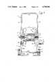
- FIG. 1shows a front view of the hose winding cart according to the present invention, which illustrates the connecting systems for the reversible connections of the different component elements, which systems are cut-away in part;
- FIG. 2shows the same cart of FIG. 1, in a side view thereof;
- FIG. 3shows an element forming a half-spool, in a front view taken from the inner side of the spool after assembly thereof;
- FIG. 4is a side cross-sectional view of FIG. 3, taken along the line I--I;
- FIG. 5shows an enlarged view of the connection of the two half-spools shown in the preceding FIGS. 3 and 4, in order to form the winding spool;
- FIG. 6is a front view of one of the lateral elements, connecting both the handle and the base and supporting the spool studs, which element is taken from the side thereof inside the cart after the assembling thereof;
- FIG. 7shows the same element of FIG. 6, in a side view thereof with, some parts being cut-away along the lines II--II of FIG. 6;
- FIG. 8shows, in a partial cut-away front view, the lateral stud acting also as a connection system for both the hose for the external connection and the hose to be wound around the spool;
- FIG. 9shows, in a partial cut-away front view, the other lateral stud provided with a handle for winding the hose;
- FIG. 10shows, in a partial cut-away front view and in an enlarged scale, the connection systems of a lateral element to a corresponding half-spool, which is obtained by means of the stud acting as a connection element for both the hose for the external connection and the hose to be wound around the spool, as well as for the base element;
- FIG. 11is an enlarged view like that of FIG. 10, which illustrates the connection system for the lateral element which is opposite to the relevant half-spool, wherein such a connection system is obtained by means of the stud comprising the winding crank;
- FIGS. 12, 13 and 14show the wheel stud in an end view and side views, respectively, wherein FIG. 14 is a sectioned view taken along the line III--III of FIG. 12;
- FIG. 15shows a cut-away view of the assembling system of a wheel to the base element of the hose winding cart according to the present invention
- FIGS. 16 and 17, respectivelyare a partial cut-away front view and a corresponding side view of an enlargement element, which may be inserted between the two half-spools for obtaining an enlargement of the same spool;
- FIG. 18shows, in a front view similar to FIG. 1, a cart provided with an enlarged spool, which has been obtained by means of the enlargement element illustrated in FIGS. 16 and 17.
- the hose winding cart according to the present inventionis constituted by the following component elements:
- a handle 1formed by an inverted "U" shaped metallic tube, which includes a transversal portion 11 having end portions from which two lateral arms 12 are orthogonally extended. Radially extending through holes 121 are provided near the free end portions of these arms facing each other for receiving respective coupling pins 361 of lateral elements 3, as will be hereinafter described.
- two opposite grooves 122are also provided in the respective free end portions of the lateral arms 12, for purposes which will also be hereinafter described;
- a base element 2which is also formed by an "U" shaped metallic tube and includes, like the previously described handle 1, a support surface engaging transverse portion 21 having ends from which two lateral arms 22 are orthogonally extended therefrom, the ends of the lateral arms being bent slightly more than 90° back towards the transverse portion to form upwardly extending portions 22a provided with through holes 221 near the free ends thereof facing each other for receiving coupling pins 361 of the lateral elements 3 in the same manner as the above specified through holes 121 of the handle 1.
- a transversal tubular portion 23is connected, preferably by welding, at the vertices of the bent zones between the lateral arms 22 and the upwardly extending portions 22a, the ends of which portion are slightly projected beyond the outer sides of the structure of the base element 2.
- the transversal tubular portion 23is provided near its ends with two diametrically opposite through holes 231, in which coupling teeth 85 of studs 8 of wheels 7 will be engaged (see also FIG. 15), in a manner which will be hereinafter described.
- V-shaped lateral element 3clearly illustrated with reference particularly to FIGS. 6 and 7, which element is formed by two tapered arms 31, joined at their wide ends to each other and appropriately tapered towards their narrower free ends, the arms 31 oriented to be convergent in such a manner as to form an angle of approximately 120° therebetween.
- a cylindrical bush 32is formed on the element 3 at a position corresponding to a vertex zone equidistant from the free ends of the arms 31 and is provided with two longitudinal grooves 321, whose function will be described later.
- each body 33having an inner diameter which is equal to the outer diameter of the tubular ends of the lateral arms of either the handle 1 or the base 2, which engage with them in a manner which will be described as follows.
- the part of the hollow cylindrical bodies 33 which faces the inside of the cart, when the latter has been assembled,includes a longitudinal opening 34 extended for a sufficient length from the inner end 35 thereof, and a resilient tongue 36 is provided inside the opening 34 and is extended from the inner end 35 of the same, which resilient tongue 36 is provided with a coupling pin 361 capable of being engaged within a respective one of the through holes 121 or 122.
- a transversally extending relief 37is provided on the inner end 35 of the cylindrical body 33 to permit the above specified two opposite grooves 122 to be engaged therewith, which grooves in turn are provided at the free ends of either lateral arms 12 of the handle 1 or the portions 22a of the base element 2, thereby preventing transversal movements of these free ends;
- a first stud 4clearly illustrated with reference particularly to FIG. 8, which is formed by a hollow cylindrical body 41 having an outer diameter equal to a respective one of the holes determined by the cylindrical bushes 32 of the lateral elements 3, as well as equal to the diameter of holes provided in cylindrical bushes 623, which in turn are disposed at the central zone of lateral flanges 62 of a winding spool 6.
- An annular flange 42is provided adjacent one end of the first stud 4 which projects radially outwardly from the outer periphery thereof. Located between the end of the first stud 4 and the annular flange 42 is a first male part 43 of a quickly connecting joint.
- first stud 4terminates, on the other hand, with an outer threaded portion 44 in which a corresponding inner threaded ring nut 45 is engaged, form which a second male part 46 which is also of a quickly connecting joint, equal to the previous one, is extended.
- two tongues 47which are complementary to said longitudinal grooves 321 in which they may be engaged, are provided on the outer periphery of the first stud 4 near the threaded portion 44, in such a manner that the stud 4 is prevented from being rotated in the cylindrical bush 32, as will be described later;
- FIG. 9is formed by a hollow cylindrical body 51 having the same diameter as that of the first stud 4 and terminating at its free end with a plurality of longitudinal notches, which extend through the hollow cylindrical body 51 so as to define a plurality of resilient tongues 52 therebetween, the tongues being provided at their free ends with teeth 53 projecting radially outwardly therefrom, whose function will be described later.
- two tongues 57which are complementary to longitudinal grooves 624 provided in the bush 623 of the spool 6 are provided on the outer periphery of the second stud 5 near the resilient tongues 52 which permits, as it will be hereinafter described, the tongues 57 to be engaged with the longitudinal grooves 624 so as to connect together both the spool 6 and a crank 54 extending from the opposite end of the second stud 5, which actuates the spool.
- One end of an arm 541 of the crank 54extends radially from the other end of the stud 5 and a hollow cylindrical body 542 extends from the other end of the arm 541, which body constitutes a journal for a handle 55 of the crank 54.
- this journalterminates at its free end with a plurality of resilient tongues 543, provided with radially outwardly projecting teeth 544 at their respective free ends thereof.
- the handle 55is constituted by a tubular cylindrical body 551 having a raised edge 552 at one end thereof situated near the arm 541 and the tubular cylindrical body 551 is provided with a radially inwardly extending flange 553 near its other end.
- a half-spool 61clearly illustrated in FIGS. 3 and 4 and constituted by a discoidal body 621, provided with suitable radially extending stiffening ribs 622 forming a lateral flange 62, wherein the discoidal body 621 comprises at its central zone a cylindrical bush 623 provided with two diametrically opposed longitudinally extending grooves 624, whose function will be described later.
- two diametrically and symmetrically opposed partly circular shells 63extend longitudinally from the inwardly facing surface of the discoidal body 621, when the latter is assembled as described later, which shells constitute one half of the spool drum obtained in a manner which will be hereinafter described.
- Such partly circular shells 63are provided with a curved surface 64 extending about 1/4 of the corresponding circumference formed by the two shells, the lateral edges of each shell 63 being provided with longitudinally extending tubular cylindrical elements 65, which are disposed at the radially inner side thereof and terminate at their free ends with two male parts 66 on one of the shells 63 and two female parts 67 of snap connecting elements on the other one of the shells 63.
- Each of the two male parts 66is constituted by a short tubular portion 661 having a reduced outer diameter, extending from the free end of the corresponding tubular cylindrical element 65 and provided inwardly thereof with a radially inwardly extending annular flange 662.
- each of the two female parts 67is constituted by two longitudinally extending resilient tongues 671 projecting from an inner transversal element 672 and terminating inside of and near the free end of the corresponding tubular cylindrical element 65.
- the tongues 671are each provided with a radially outwardly extending tooth 673 engageable with the inner side of a respective annular flange 662 of the corresponding male part 66, thereby positioning the tooth in correspondence with one of the openings 663;
- a wheel 7clearly illustrated in FIG. 15 and constituted by a discoidal body 71, provided at its central part with a cylindrical bush 72 as well as a cylindrical body 73 at its peripheral part, which body is projected from the same side of the discoidal body 71 as the central cylindrical bush 72 and forms the rolling surface of the wheel 7;
- the wheel stud 8of the wheel 7, which is able to fix the wheel over a corresponding end of the transversal tubular portion 23 of the base element 2 described earlier.
- the wheel stud 8, clearly illustrated in FIGS. 9, 10 and 11,is constituted by a cylindrical body comprising a first portion 81 forming the effective stud of the wheel 7 and provided at its one end with a radially outwardly extending annular rim 83, as well as with a second reduced diameter cylindrical portion 84 extended therefrom at its other end, which portion has an outer diameter equal to the inner diameter of the transversal tubular portion 23, in which it will be introduced as described later.
- the free end of the second cylindrical portion 84is provided with longitudinally extending notches which define a pair of diametrically opposed resilient tongues 85 therebetween' which are provided at their respective free ends with corresponding teeth 86, which are radially outwardly protruding therefrom and are engageable with corresponding holes 231 provided in the transversal tubular portion 23.
- the cart of the present inventionmay be assembled easily and in a very simple manner, and it also may be disassembled without the need of any tool.
- novel shapes of the single components thereofis such as to permit that most parts of the same components carry out double functions, a fact which permits a reduction of the means foreseen for their manufacture to be obtained. In the case referred to, this reduction is related to the molds.
- the wheels 7 and the relevant studs 8 thereof, the half-spools 61 and the lateral elements 3are all symmetric elements which are disposed in an opposite symmetrical relationship to each other during the cart assembly.
- two half-spools 61are taken and disposed in an opposed position to each other, with the flanges 62 situated on the outside thereof and in such a manner that the respective snap connecting elements are positioned with the male parts 66 opposed to the corresponding female parts 67.
- the support structure of the so obtained spool 6is assembled by inserting, into the hollow cylindrical bodies 33 of the two lateral elements 3 which have been disposed in a reciprocal opposite relationship, the ends of the lateral arms 12 of the handle 1, at the one side, and the ends of the lateral arms 22 of the base element 2, at the other side thereof.
- This operationwill continue until the coupling pins 361 provided on the ends of the resilient tongues 36, which in turn are provided, as already described, in the hollow cylindrical bodies 33, penetrate into the through holes 121, 122, which are provided in the respective ends of the lateral arms referred to.
- the handle 1 and the base element 2are connected to the lateral elements 3.
- the wheels 7 and the spool 6are assembled to the so obtained support structure. That is, the wheels 7 are assembled simply by inserting a stud 8 into the hole of the respective cylindrical bush 72 and then by inserting the second cylindrical portion 84 of the same stud in a corresponding end of the transversal tubular portion 23, which is fixed onto the base element 2 as already described until the teeth 86 of this stud penetrate into the corresponding holes 231 provided in such end of the transversal tubular portion 23. In this manner, the connection of the stud 8 is ensured and the wheel 7 is fixed, as it is supported by such a stud and retained between the edge of the end of the transversal tubular portion 23 and the annular rim 83, which is disposed on the outer end portion of the stud 8. Also, this connection is easily reversible, in fact it is sufficient to push the teeth 86 inwardly, always acting with the tips of two fingers, in order to extract the stud 8 therefrom and thus disassemble the respective wheels 7.
- the spool 6is assembled to the assembled support structure simply by inserting the first stud 4 into the corresponding cylindrical bush 32 of the two lateral elements 3, as well as into the corresponding cylindrical bush 623 of the lateral flanges 62 of the spool 6, at the one side thereof, and the second stud 5 into the same components at the other side thereof.
- the first stud 4is inserted initially from the inner side of the spool 6 into the relevant cylindrical bush 623 and then into the cylindrical bush 32 of the corresponding lateral element 3, in such a manner that the tongues 47 of the same penetrate into the relative longitudinal grooves 321, which are provided within the cylindrical bush 32 as previously described.
- the relative inner threaded ring nut 45is screwed onto the outer threaded portion 44, which is projected from the lateral element 3, so that the first stud 4 supports a lateral element 3 with the corresponding flange 62, so arranged as to be reciprocally fixed and retained between the annular flange 42, provided on the inner end of the stud 4, and the threaded ring nut 45.
- the stud 5is simply inserted initially into the cylindrical bush 32 of the other lateral element 3 and then into the cylindrical bush 623 of the corresponding lateral flange 62 of the spool 6, in which the respective tongues 57 penetrate into the corresponding longitudinal grooves 624 of the respective half-spool 61.
- the spool 6is supported at both sides thereof and the crank 54 may drive in in rotation, as the crank 54 is connected to the spool by means of the connection constituted by the tongues 57 and the longitudinal grooves 624.
- the teeth 53 provided at the ends of the resilient tongues 52will push the latter inwardly, while passing through the cylindrical bushes 32 and 623 and expand outwardly just after they have passed the inner edge of the cylindrical bush 623, so that these teeth will engage themselves with the inner edge of the cylindrical bush 623, thereby preventing the latter from being extracted therefrom.
- the relevant extraction thereofmay be effected simply by pushing the teeth 53 inwardly, always acting on the same with only the tips of two fingers.
- the hose winding cart referred tois completely assembled and may be always not only assembled but also disassembled in a very simple and easy manner, without the need of any tool, as clearly set forth above.
- such a hose winding cartmay be easily enlarged by using an enlargement element 9, clearly illustrated in FIGS. 16 and 17, which is similar to one of the partly circular shells 63 of the half-spool referred to above.
- the enlargement element 9is constituted by a cylindrical surface portion 94, equal to the cylindrical surface 64 of the circular shells 63, the lateral edges of which are also provided with tubular cylindrical elements 95, which are also equivalent to the tubular cylindrical elements 65, wherein the tubular cylindrical elements 95 terminate with two male parts 96, at the one side thereof, and with two female parts 97 at the other side, which parts in turn are completely equal to the respective male parts 66 and female parts 67 of the circular shells 63 of the half-spools 61.
- FIG. 18clearly illustrates a cart of the kind referred to, which has been enlarged by using a pair of such enlargement elements 9.
- handles 1 and base elements 2also having greater sizes, in the transversal direction thereof, while the other components of the carts remain always the same.
- This cartpermits various advantages to be obtained.
- the simplicity of the assembling and disassembling system thereofallows its components to be packed within small-sized boxes, which fact is particularly useful during both the packaging and the transport of the same components.
- the inventionwhich has been described, allows the use of elements having a double function, a fact which permits their manufacturing costs as well as the investment costs for the molds involved in their manufacture of be cut down.
Landscapes
- Handcart (AREA)
- Storing, Repeated Paying-Out, And Re-Storing Of Elongated Articles (AREA)
- Forklifts And Lifting Vehicles (AREA)
- Catching Or Destruction (AREA)
- Storage Of Web-Like Or Filamentary Materials (AREA)
Abstract
Description
Claims (20)
Applications Claiming Priority (2)
| Application Number | Priority Date | Filing Date | Title |
|---|---|---|---|
| IT45723/86AIT1204220B (en) | 1986-05-02 | 1986-05-02 | HOSE REEL TROLLEY |
| IT45723A/86 | 1986-05-02 |
Publications (1)
| Publication Number | Publication Date |
|---|---|
| US4768546Atrue US4768546A (en) | 1988-09-06 |
Family
ID=11257721
Family Applications (1)
| Application Number | Title | Priority Date | Filing Date |
|---|---|---|---|
| US07/040,474Expired - LifetimeUS4768546A (en) | 1986-05-02 | 1987-04-20 | Hose winding cart |
Country Status (6)
| Country | Link |
|---|---|
| US (1) | US4768546A (en) |
| EP (1) | EP0243884B2 (en) |
| AT (1) | ATE55756T1 (en) |
| DE (1) | DE3764393D1 (en) |
| ES (1) | ES2017663T5 (en) |
| IT (1) | IT1204220B (en) |
Cited By (49)
| Publication number | Priority date | Publication date | Assignee | Title |
|---|---|---|---|---|
| USD303446S (en) | 1987-08-12 | 1989-09-12 | Suncast Corporation | Portable hose cart |
| US5007598A (en)* | 1989-10-25 | 1991-04-16 | O. Ames Co. | Hose reel assembly |
| US5046520A (en)* | 1990-02-05 | 1991-09-10 | Suncast Corporation | Portable hose cart |
| US5056553A (en)* | 1990-08-07 | 1991-10-15 | Suncast Corporation | Portable hose cart |
| USD321123S (en) | 1990-04-12 | 1991-10-29 | Hunter-Melnor, Inc. | Hose reel cart |
| USD323916S (en) | 1990-03-14 | 1992-02-11 | Suncast Corporation | Hose cart with tray |
| US5109882A (en)* | 1991-02-21 | 1992-05-05 | Eley John H | Hose reel |
| USD326549S (en) | 1990-08-07 | 1992-05-26 | Suncast Corporation | Hose cart |
| USD328173S (en) | 1990-07-13 | 1992-07-21 | The Specialty Mfg. Co. | Garden hose reel caddy |
| USD330506S (en) | 1990-07-11 | 1992-10-27 | Gardena Kress + Kastner Gmbh | Hose Reel |
| USD330847S (en) | 1990-07-11 | 1992-11-10 | Gardena Kress+Kastner Gmbh | Hose reel cart |
| US5179972A (en)* | 1991-02-21 | 1993-01-19 | Eley John H | Hose reel |
| USD343710S (en) | 1992-06-15 | 1994-01-25 | Claber S.P.A. | Hose cart |
| US5308011A (en)* | 1991-07-31 | 1994-05-03 | Claber S.P.A. | Supporting side for a hose-winding drum for a device for winding flexible hose |
| USD349039S (en) | 1992-05-19 | 1994-07-26 | Melnor Inc. | Hose reel |
| USD352149S (en) | 1993-05-20 | 1994-11-01 | The Specialty Mfg. Co. | Portable hose reel caddy |
| US5381981A (en)* | 1993-05-20 | 1995-01-17 | The Specialty Mfg. Co. | Garden hose reel |
| US5425391A (en)* | 1994-09-12 | 1995-06-20 | Suncast Corporation | Stackable hose reel cart |
| US5462298A (en)* | 1994-12-07 | 1995-10-31 | Bodine; Daryl L. | Water hose cart |
| US5520212A (en)* | 1995-04-04 | 1996-05-28 | Williams; Ray F. | Self winding hose reel |
| US5657789A (en)* | 1995-08-11 | 1997-08-19 | Suncast Corporation | Wall mount stackable hose reel |
| USD392080S (en) | 1996-03-05 | 1998-03-10 | Suncast Corporation | Industrial hose cart |
| US5758685A (en)* | 1996-03-05 | 1998-06-02 | Suncast Corporation | Industrial hose cart |
| US5797424A (en)* | 1995-08-11 | 1998-08-25 | Suncast Corporation | Hose reel |
| US5934598A (en)* | 1996-08-23 | 1999-08-10 | Alert Stamping & Mfg. Co., Inc. | Manually operated cord storage reel |
| US5988552A (en)* | 1998-11-12 | 1999-11-23 | Suncast Corporation | Portable hose reel cart having a folding handle |
| US20050092366A1 (en)* | 2003-10-31 | 2005-05-05 | Schaller James M. | Hose reel with integral hub assembly |
| US6932106B1 (en)* | 2004-11-19 | 2005-08-23 | King-Yuan Wang | Hose reel |
| US20070038133A1 (en)* | 2005-08-12 | 2007-02-15 | Omron Healthcare Co., Ltd. | Blood pressure measuring device |
| US7252193B1 (en) | 2003-05-07 | 2007-08-07 | John Gordon Lewis | Storage |
| US20070197923A1 (en)* | 2006-01-13 | 2007-08-23 | Omron Healthcare Co., Ltd. | Blood pressure measuring device |
| US20080023579A1 (en)* | 2006-07-27 | 2008-01-31 | Alemite Llc | Modular reel assembly |
| USD584937S1 (en) | 2007-01-31 | 2009-01-20 | Alert Safety Lite Products Co., Inc. | Cord reel |
| USD590566S1 (en)* | 2008-07-28 | 2009-04-14 | Ames True Temper, Inc. | Metal cart |
| WO2006075137A3 (en)* | 2005-01-12 | 2009-08-13 | Hozelock Ltd | Cased hose reels |
| USD604020S1 (en)* | 2009-04-13 | 2009-11-10 | Ames True Temper, Inc. | Hose reel |
| USD604019S1 (en)* | 2009-04-13 | 2009-11-10 | Ames True Temper, Inc. | Hose reel |
| USD604021S1 (en)* | 2009-07-13 | 2009-11-10 | Ames True Temper, Inc. | Hose reel |
| USD604244S1 (en) | 2007-10-10 | 2009-11-17 | Alert Stamping & Manufacturing Co., Inc. | Cord reel |
| WO2009016615A3 (en)* | 2007-07-30 | 2010-03-04 | Sharona Keren | Conduit reel for dripper irrigation line |
| US20100102157A1 (en)* | 2008-10-23 | 2010-04-29 | Ames True Temper, Inc. | Deck box |
| US7766272B2 (en) | 2007-12-10 | 2010-08-03 | Suzhou Kingclean Floorcare Co., Ltd. | Rotating apparatus for winding reel of high-pressure cleaner |
| USD646039S1 (en)* | 2010-06-17 | 2011-09-27 | Claber S.P.A. | Hose winding cart |
| US20110309182A1 (en)* | 2010-06-17 | 2011-12-22 | Gaetano Franchini | Hose reel cart with metal drum and height-adjustable manoeuvring handle |
| US20120255627A1 (en)* | 2011-04-08 | 2012-10-11 | Ames True Temper, Inc. | Hose reel assembly having limited hardware |
| CN102730481A (en)* | 2011-04-08 | 2012-10-17 | 亚美斯特鲁坦普公司 | Hose reel having a horizontally split frame |
| US8851413B2 (en) | 2012-11-02 | 2014-10-07 | Suncast Technologies, Llc | Reel assembly |
| US9126612B2 (en)* | 2013-08-22 | 2015-09-08 | Hsiu-Man Yu Chen | Cable reel trolley |
| US10035531B2 (en) | 2015-11-20 | 2018-07-31 | Bridging Gaps, LLC | Cart |
Families Citing this family (7)
| Publication number | Priority date | Publication date | Assignee | Title |
|---|---|---|---|---|
| GB8902658D0 (en)* | 1989-02-07 | 1989-03-30 | Briggs Irrigation Uk Ltd | Equipment handler |
| DE29723788U1 (en)* | 1997-03-14 | 1999-03-25 | Gloria-Werke H. Schulte-Frankenfeld Gmbh & Co, 59329 Wadersloh | Hose reel for hose trolleys or carriers |
| IT237643Y1 (en)* | 1997-07-07 | 2000-09-13 | Claber Spa | DRUM FOR WINDING TROLLEYS FOR FLEXIBLE HOSES FOR IRRIGATION |
| IT243437Y1 (en)* | 1997-10-23 | 2002-03-04 | Uniflex Utiltime Spa | HOSE REEL TROLLEY FOR IRRIGATION |
| EP2640654B1 (en)* | 2010-11-17 | 2014-10-01 | Husqvarna AB | Tube and mounting frame assembly |
| DE202011004378U1 (en) | 2011-03-24 | 2011-06-01 | SILAG Handel AG, 40764 | Hose trolley with double reel and hose connector |
| ITMO20140025U1 (en)* | 2014-07-21 | 2016-01-21 | Gf Srl | SUPPORT FOR A TUBE |
Citations (6)
| Publication number | Priority date | Publication date | Assignee | Title |
|---|---|---|---|---|
| US3977429A (en)* | 1972-12-15 | 1976-08-31 | Stevenson James S | Hose reel assembly |
| US4137939A (en)* | 1977-10-11 | 1979-02-06 | Melnor Industries | Hose reel cart |
| FR2452458A1 (en)* | 1979-03-29 | 1980-10-24 | Contact Gmbh | CABLE WINDER WITH A TWO-PART HOUSING |
| EP0131219A1 (en)* | 1983-07-09 | 1985-01-16 | REHAU AG + Co | Coiling machine |
| US4506698A (en)* | 1983-07-07 | 1985-03-26 | Suncast Corporation | Garden hose storage apparatus |
| US4512361A (en)* | 1982-11-29 | 1985-04-23 | Suncast Corporation | Hose storage apparatus |
- 1986
- 1986-05-02ITIT45723/86Apatent/IT1204220B/enactive
- 1987
- 1987-04-20USUS07/040,474patent/US4768546A/ennot_activeExpired - Lifetime
- 1987-04-23DEDE8787105970Tpatent/DE3764393D1/ennot_activeExpired - Fee Related
- 1987-04-23ESES87105970Tpatent/ES2017663T5/ennot_activeExpired - Lifetime
- 1987-04-23ATAT87105970Tpatent/ATE55756T1/ennot_activeIP Right Cessation
- 1987-04-23EPEP87105970Apatent/EP0243884B2/ennot_activeExpired - Lifetime
Patent Citations (6)
| Publication number | Priority date | Publication date | Assignee | Title |
|---|---|---|---|---|
| US3977429A (en)* | 1972-12-15 | 1976-08-31 | Stevenson James S | Hose reel assembly |
| US4137939A (en)* | 1977-10-11 | 1979-02-06 | Melnor Industries | Hose reel cart |
| FR2452458A1 (en)* | 1979-03-29 | 1980-10-24 | Contact Gmbh | CABLE WINDER WITH A TWO-PART HOUSING |
| US4512361A (en)* | 1982-11-29 | 1985-04-23 | Suncast Corporation | Hose storage apparatus |
| US4506698A (en)* | 1983-07-07 | 1985-03-26 | Suncast Corporation | Garden hose storage apparatus |
| EP0131219A1 (en)* | 1983-07-09 | 1985-01-16 | REHAU AG + Co | Coiling machine |
Cited By (56)
| Publication number | Priority date | Publication date | Assignee | Title |
|---|---|---|---|---|
| USD303446S (en) | 1987-08-12 | 1989-09-12 | Suncast Corporation | Portable hose cart |
| US5007598A (en)* | 1989-10-25 | 1991-04-16 | O. Ames Co. | Hose reel assembly |
| US5046520A (en)* | 1990-02-05 | 1991-09-10 | Suncast Corporation | Portable hose cart |
| USD323916S (en) | 1990-03-14 | 1992-02-11 | Suncast Corporation | Hose cart with tray |
| USD321123S (en) | 1990-04-12 | 1991-10-29 | Hunter-Melnor, Inc. | Hose reel cart |
| USD330847S (en) | 1990-07-11 | 1992-11-10 | Gardena Kress+Kastner Gmbh | Hose reel cart |
| USD330506S (en) | 1990-07-11 | 1992-10-27 | Gardena Kress + Kastner Gmbh | Hose Reel |
| USD328173S (en) | 1990-07-13 | 1992-07-21 | The Specialty Mfg. Co. | Garden hose reel caddy |
| US5056553A (en)* | 1990-08-07 | 1991-10-15 | Suncast Corporation | Portable hose cart |
| USD326549S (en) | 1990-08-07 | 1992-05-26 | Suncast Corporation | Hose cart |
| US5109882A (en)* | 1991-02-21 | 1992-05-05 | Eley John H | Hose reel |
| US5179972A (en)* | 1991-02-21 | 1993-01-19 | Eley John H | Hose reel |
| US5308011A (en)* | 1991-07-31 | 1994-05-03 | Claber S.P.A. | Supporting side for a hose-winding drum for a device for winding flexible hose |
| USD349039S (en) | 1992-05-19 | 1994-07-26 | Melnor Inc. | Hose reel |
| USD343710S (en) | 1992-06-15 | 1994-01-25 | Claber S.P.A. | Hose cart |
| USD352149S (en) | 1993-05-20 | 1994-11-01 | The Specialty Mfg. Co. | Portable hose reel caddy |
| US5381981A (en)* | 1993-05-20 | 1995-01-17 | The Specialty Mfg. Co. | Garden hose reel |
| US5425391A (en)* | 1994-09-12 | 1995-06-20 | Suncast Corporation | Stackable hose reel cart |
| US5462298A (en)* | 1994-12-07 | 1995-10-31 | Bodine; Daryl L. | Water hose cart |
| US5520212A (en)* | 1995-04-04 | 1996-05-28 | Williams; Ray F. | Self winding hose reel |
| US5657789A (en)* | 1995-08-11 | 1997-08-19 | Suncast Corporation | Wall mount stackable hose reel |
| US5797424A (en)* | 1995-08-11 | 1998-08-25 | Suncast Corporation | Hose reel |
| USD392080S (en) | 1996-03-05 | 1998-03-10 | Suncast Corporation | Industrial hose cart |
| US5758685A (en)* | 1996-03-05 | 1998-06-02 | Suncast Corporation | Industrial hose cart |
| US5934598A (en)* | 1996-08-23 | 1999-08-10 | Alert Stamping & Mfg. Co., Inc. | Manually operated cord storage reel |
| US5988552A (en)* | 1998-11-12 | 1999-11-23 | Suncast Corporation | Portable hose reel cart having a folding handle |
| US7252193B1 (en) | 2003-05-07 | 2007-08-07 | John Gordon Lewis | Storage |
| US20050092366A1 (en)* | 2003-10-31 | 2005-05-05 | Schaller James M. | Hose reel with integral hub assembly |
| US6978960B2 (en) | 2003-10-31 | 2005-12-27 | Schaller James M | Hose reel with integral hub assembly |
| US6932106B1 (en)* | 2004-11-19 | 2005-08-23 | King-Yuan Wang | Hose reel |
| WO2006075137A3 (en)* | 2005-01-12 | 2009-08-13 | Hozelock Ltd | Cased hose reels |
| EP1752090A3 (en)* | 2005-08-12 | 2007-08-29 | Omron Healthcare Co., Ltd. | Blood pressure measuring device |
| US7722543B2 (en) | 2005-08-12 | 2010-05-25 | Omron Healthcare Co., Ltd. | Blood pressure measuring device |
| US20070038133A1 (en)* | 2005-08-12 | 2007-02-15 | Omron Healthcare Co., Ltd. | Blood pressure measuring device |
| US20070197923A1 (en)* | 2006-01-13 | 2007-08-23 | Omron Healthcare Co., Ltd. | Blood pressure measuring device |
| US8075493B2 (en) | 2006-01-13 | 2011-12-13 | Omron Healthcare Co., Ltd. | Blood pressure measuring device |
| US20080023579A1 (en)* | 2006-07-27 | 2008-01-31 | Alemite Llc | Modular reel assembly |
| USD584937S1 (en) | 2007-01-31 | 2009-01-20 | Alert Safety Lite Products Co., Inc. | Cord reel |
| US20100301137A1 (en)* | 2007-07-30 | 2010-12-02 | Keren Sharona | Conduit reel for dripper irrigation line |
| WO2009016615A3 (en)* | 2007-07-30 | 2010-03-04 | Sharona Keren | Conduit reel for dripper irrigation line |
| USD604244S1 (en) | 2007-10-10 | 2009-11-17 | Alert Stamping & Manufacturing Co., Inc. | Cord reel |
| US7766272B2 (en) | 2007-12-10 | 2010-08-03 | Suzhou Kingclean Floorcare Co., Ltd. | Rotating apparatus for winding reel of high-pressure cleaner |
| USD590566S1 (en)* | 2008-07-28 | 2009-04-14 | Ames True Temper, Inc. | Metal cart |
| US20100102157A1 (en)* | 2008-10-23 | 2010-04-29 | Ames True Temper, Inc. | Deck box |
| US9073730B2 (en) | 2008-10-23 | 2015-07-07 | The Ames Companies, Inc. | Deck box |
| USD604019S1 (en)* | 2009-04-13 | 2009-11-10 | Ames True Temper, Inc. | Hose reel |
| USD604020S1 (en)* | 2009-04-13 | 2009-11-10 | Ames True Temper, Inc. | Hose reel |
| USD604021S1 (en)* | 2009-07-13 | 2009-11-10 | Ames True Temper, Inc. | Hose reel |
| USD646039S1 (en)* | 2010-06-17 | 2011-09-27 | Claber S.P.A. | Hose winding cart |
| US20110309182A1 (en)* | 2010-06-17 | 2011-12-22 | Gaetano Franchini | Hose reel cart with metal drum and height-adjustable manoeuvring handle |
| US8590825B2 (en)* | 2010-06-17 | 2013-11-26 | Claber S.P.A. | Hose reel cart with metal drum and height-adjustable manoeuvring handle |
| US20120255627A1 (en)* | 2011-04-08 | 2012-10-11 | Ames True Temper, Inc. | Hose reel assembly having limited hardware |
| CN102730481A (en)* | 2011-04-08 | 2012-10-17 | 亚美斯特鲁坦普公司 | Hose reel having a horizontally split frame |
| US8851413B2 (en) | 2012-11-02 | 2014-10-07 | Suncast Technologies, Llc | Reel assembly |
| US9126612B2 (en)* | 2013-08-22 | 2015-09-08 | Hsiu-Man Yu Chen | Cable reel trolley |
| US10035531B2 (en) | 2015-11-20 | 2018-07-31 | Bridging Gaps, LLC | Cart |
Also Published As
| Publication number | Publication date |
|---|---|
| EP0243884B1 (en) | 1990-08-22 |
| ES2017663T5 (en) | 1996-04-16 |
| ATE55756T1 (en) | 1990-09-15 |
| ES2017663B3 (en) | 1991-03-01 |
| EP0243884B2 (en) | 1995-12-06 |
| IT1204220B (en) | 1989-03-01 |
| IT8645723A0 (en) | 1986-05-02 |
| DE3764393D1 (en) | 1990-09-27 |
| EP0243884A1 (en) | 1987-11-04 |
Similar Documents
| Publication | Publication Date | Title |
|---|---|---|
| US4768546A (en) | Hose winding cart | |
| US5007598A (en) | Hose reel assembly | |
| CA1319018C (en) | Appliance for scrub clearance, grass cutting or the like, with devices for lengthening the cutting line and coupling devices | |
| JPH0416765Y2 (en) | ||
| US5138911A (en) | Telescopic wrench extensioner | |
| US4027987A (en) | Joining device for connecting tubes | |
| US3940085A (en) | Collapsible reel | |
| US4388012A (en) | Swivel connector | |
| US4050136A (en) | Bearing race driver | |
| US4915422A (en) | Pipe coupling | |
| US4722468A (en) | Boiler pipe tool for heliarc welding with tongue and groove interlock | |
| US5199322A (en) | Handlebar assembly for cycles | |
| US5178585A (en) | Chain with easily adjustable number of links | |
| CA1164411A (en) | Tape joint for cylindrical members | |
| US3079188A (en) | Demountable coupling | |
| NO161212B (en) | THREE ARMED CLUTCH FOR PIPE FORMED STRUCTURES. | |
| US5687623A (en) | Reversible socket wrench | |
| US4007650A (en) | Garden hose coupling tool | |
| US5943923A (en) | Retaining device of socket spanner | |
| US3045455A (en) | Unviersal joint for shafts | |
| US2701740A (en) | Wheel structure | |
| JPS6214401B2 (en) | ||
| US3408850A (en) | Tube bending mandrel | |
| US4167118A (en) | Wheel fixing device | |
| US4090737A (en) | Agricultural spoke wheel |
Legal Events
| Date | Code | Title | Description |
|---|---|---|---|
| AS | Assignment | Owner name:UNIFLEX UTILTIME S.P.A., VIA DELL'INDUSTRIA, MONTE Free format text:ASSIGNMENT OF ASSIGNORS INTEREST.;ASSIGNORS:BRUSADIN, GIACOMO;BORGHESE, ALLADINO;REEL/FRAME:004726/0947 Effective date:19870603 Owner name:UNIFLEX UTILTIME S.P.A., VIA DELL'INDUSTRIA,ITALY Free format text:ASSIGNMENT OF ASSIGNORS INTEREST;ASSIGNORS:BRUSADIN, GIACOMO;BORGHESE, ALLADINO;REEL/FRAME:004726/0947 Effective date:19870603 | |
| STCF | Information on status: patent grant | Free format text:PATENTED CASE | |
| CC | Certificate of correction | ||
| FEPP | Fee payment procedure | Free format text:PAT HLDR NO LONGER CLAIMS SMALL ENT STAT AS SMALL BUSINESS (ORIGINAL EVENT CODE: LSM2); ENTITY STATUS OF PATENT OWNER: LARGE ENTITY | |
| FPAY | Fee payment | Year of fee payment:4 | |
| FPAY | Fee payment | Year of fee payment:8 | |
| FEPP | Fee payment procedure | Free format text:PAYOR NUMBER ASSIGNED (ORIGINAL EVENT CODE: ASPN); ENTITY STATUS OF PATENT OWNER: LARGE ENTITY | |
| FPAY | Fee payment | Year of fee payment:12 |