US4768505A - Calculus crushing apparatus - Google Patents
Calculus crushing apparatusDownload PDFInfo
- Publication number
- US4768505A US4768505AUS07/042,476US4247687AUS4768505AUS 4768505 AUS4768505 AUS 4768505AUS 4247687 AUS4247687 AUS 4247687AUS 4768505 AUS4768505 AUS 4768505A
- Authority
- US
- United States
- Prior art keywords
- sheath
- basket
- main body
- operation wire
- connecting member
- Prior art date
- Legal status (The legal status is an assumption and is not a legal conclusion. Google has not performed a legal analysis and makes no representation as to the accuracy of the status listed.)
- Expired - Lifetime
Links
Images


Classifications
- A—HUMAN NECESSITIES
- A61—MEDICAL OR VETERINARY SCIENCE; HYGIENE
- A61B—DIAGNOSIS; SURGERY; IDENTIFICATION
- A61B17/00—Surgical instruments, devices or methods
- A61B17/22—Implements for squeezing-off ulcers or the like on inner organs of the body; Implements for scraping-out cavities of body organs, e.g. bones; for invasive removal or destruction of calculus using mechanical vibrations; for removing obstructions in blood vessels, not otherwise provided for
- A61B17/221—Gripping devices in the form of loops or baskets for gripping calculi or similar types of obstructions
- A61B2017/2212—Gripping devices in the form of loops or baskets for gripping calculi or similar types of obstructions having a closed distal end, e.g. a loop
- A—HUMAN NECESSITIES
- A61—MEDICAL OR VETERINARY SCIENCE; HYGIENE
- A61B—DIAGNOSIS; SURGERY; IDENTIFICATION
- A61B17/00—Surgical instruments, devices or methods
- A61B17/28—Surgical forceps
- A61B17/29—Forceps for use in minimally invasive surgery
- A61B17/2909—Handles
- A61B2017/2912—Handles transmission of forces to actuating rod or piston
- A61B2017/2923—Toothed members, e.g. rack and pinion
Definitions
- the present inventionrelates to a calculus crushing apparatus for crushing a calculus produced in a body cavity.
- a calculus produced in internal organs such as a bile duct or a urinary bladderadversely affects a patient.
- an enlarged calculusgives much pain to a patient. Therefore, a calculus crushing apparatus is inserted in a body cavity through an endoscope and crushes the calculus produced in the body cavity to remove it from the body or removes it without crushing.
- a calculus crushing apparatus of this typeincludes a sheath having a hard portion at its distal end and inserted in a body cavity with an endoscope, an operation wire inserted in the sheath, and a basket constituted by a plurality of elastic wires and fixed at the distal end of the operation wire.
- a connecting rodis fixed to the proximal end of the operation wire and is reciprocated by an operation section to expand or contract the basket.
- the present inventionhas been made in consideration of the above circumstances, and has as its object to provide a calculus crushing apparatus which can prevent disconnection of the basket and the operation wire even when a large tension acts thereon during a crushing operation.
- a calculus crushing apparatus of the present inventioncomprises a basket connected to the distal end of an operation wire and constituted by a plurality of elastic wires, and an elongated connecting member connected to the proximal end of the operation wire.
- the connecting memberhas a disconnecting portion with a strength lower than those of the elastic wires and the operation wire against tension.
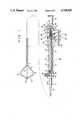
- FIGS. 1 to 9show a calculus crushing apparatus according to an embodiment of the present invention, in which
- FIG. 1is a partially cutaway side view of the entire apparatus
- FIG. 2is a sectional view of a sheath of the apparatus
- FIG. 3is a sectional view taken along line III--III of FIG. 1,
- FIG. 4is a sectional view taken along line IV--IV of FIG. 1,
- FIG. 5is a side view of the distal end of the sheath with a basket closed
- FIG. 6is a schematic view for explaining how the distal end of the sheath is inserted inside a bile duct
- FIGS. 7 to 9are sectional views of the apparatus in different operation states
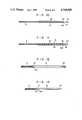
- FIGS. 10 and 11are sectional views respectively showing first and second modifications of a disconnecting portion
- FIGS. 12 and 13are sectional views respectively showing third and fourth modifications of the disconnecting portion
- FIGS. 14 and 15are side and exploded perspective views, respectively, showing a fifth modification of the disconnecting portion
- FIGS. 16 and 17are partially cutaway side and exploded perspective views, respectively, showing a sixth modification of the disconnecting portion
- FIGS. 18 and 19are sectional views respectively showing seventh and eighth modifications of the disconnecting portion
- FIGS. 20 and 21show a modification of the basket, in which FIG. 20 is a side view showing the opened basket, and FIG. 21 is a side view showing the closed basket; and
- FIG. 22is a partially cutaway view showing a modification of the sheath.
- a calculus crushing apparatusincludes flexible sheath 1 formed of, e.g., a closely wound coil.
- Tubular hard portion 2made of stainless steel or the like is fixed to the distal end of sheath 1, and mouthpiece 3 is fixed to its proximal end.
- mouthpiece 3includes first member 5 having liquid supply portion 4 and connected to the proximal end of sheath 1, and second member 6 threadably engaged with member 5.
- Through hole 7is coaxially formed through members 5 and 6.
- Liquid-tight tube 8 inserted inside sheath 1is connected to member 5 and communicates with hole 7. Tube 8 extends from mouthpiece 3 to the distal end of sheath 1.
- a syringe(not shown) may be connected to member 4 of mouthpiece 3 to supply a liquid such as a contrast medium to tube 8.
- a syringe(not shown) may be connected to member 4 of mouthpiece 3 to supply a liquid such as a contrast medium to tube 8.
- the proximal end of sheath 1is inserted and fixed in mounting pipe 14 extending from member 5.
- the proximal end of sheath 1is protected by cover 15 provided outside pipe 14.
- Basket 10 for holding and crushing a calculusis fixed to the distal end of wire 9, i.e., the end located at the side of hard portion 2. More specifically, basket 10 is constructed by connecting both ends of a plurality of elastic wires 11 with tips 12 and forming bent portions 13 midway along respective wires 11, and can be expanded/contracted, i.e., opened/closed.
- elongated straight connecting rod 16is fixed to the proximal end of wire 9 projecting from the rear end of sheath 1.
- Rod 16is slidably inserted in hole 7 of mouthpiece 3, and projects from member 6.
- O-ring 17is provided at the connecting portion between members 5 and 6 of mouthpiece 3 so that hole 7 is maintained liquid-tight. Rod 16 extends through O-ring 17.
- Mouthpiece 3is detachably connected to operation portion 18.
- portion 18includes main body 20 and grip portion 22 extending from body 20 to be held by an operator. Insertion hole 23 is formed through body 20 and portion 22 along an extending direction of portion 22.
- Connecting ring 24is mounted on the distal end of portion 22 coaxially with hole 23.
- Set screw 25is screwed in ring 24 to be radially reciprocated.
- the rear end of member 6 of mouthpiece 3is inserted in ring 24, and screw 25 is screwed therein so that its distal end engages with groove 6a formed in the outer surface of the rear end of member 6, thereby connecting mouthpiece 3 with portion 18.
- rod 16is inserted in hole 23.
- rack 26is slidably inserted in hole 23 of portion 18.
- Rack 26has a substantially circular cross-section, and teeth 27 are formed on one radial side substantially throughout the entire axial length of rack 26.
- Guide groove 28 opened at an outer surface opposite to the side of teeth 27is axially formed in rack 26 except its axial both ends.
- Through holes 30are formed in the axial both ends of rack 26 coaxially with hole 23 and respectively communicate with groove 28.
- Guide screw 31 screwed in body 20 of portion 18engages with groove 28 of rack 26, thereby preventing rotation of rack 26 in hole 23 and rack 26 from coming out hole 23.
- the rear end portion of rod 16 extending from mouthpiece 3is inserted in hole 30 and groove 28 and its extreme end projects from the rear end of rack 26.
- Holding portion 32 for sliding rack 26is connected to the rear end of rack 26 and projects from body 20 of portion 18.
- Mounting hole 34is formed in portion 32 coaxially with hole 30 of rack 26 and communicates with groove 28 through hole 30.
- the end of rod 16 having flat portion 35 (see FIG. 2)is inserted in hole 34.
- Housing hole 36is formed radially along portion 32 to across hole 34 and is opened at an outer surface of portion 32.
- Locking rod 37 having button 38 at its upper endis inserted in hole 36.
- Rod 37has engaging hole 40 formed through an axial midway portion thereof and is biased in a direction to project from portion 32 by spring 41 provided in hole 36. In order to connect rod 16 to portion 32, first, rod 37 is pressed against spring 41 so that holes 40 and 34 are aligned with each other.
- first support shaft 44is rotatably supported by bearings 42 and extends in a direction perpendicular to rack 26.
- First gear 45is fixed to one end of shaft 44, and handle 46 disposed outside body 20 is mounted on the other end thereof.
- second support shaft 50is rotatably supported by bearings 48 in body 20 and extends parallel to shaft 44.
- Gear 51 engaging with gear 45 and having teeth more than those of gear 45is mounted on one end of shaft 50.
- Cavity 52is formed in body 20. It is located at the side of teeth 27 of rack 26 and opens in hole 23.
- Shaft 50extends through cavity 52.
- Third gear 53 fitted on shaft 50is housed in cavity 52 and meshes with teeth 27 of rack 26.
- gears 45 and 50are decelerated by gears 45 and 50 and transmitted to gear 53.
- rack 26is moved by gear 53, thereby moving wire 9 forward or backward through rod 16.
- Gears 45, 51, and 53constitute reduction gear mechanism 54.
- sheath 1is inserted in an insertion channel (not shown) of an endoscope with basket 10 closed as is shown in FIG. 5 and is then inserted in a body cavity together with the endoscope. Thereafter, as is shown in FIG. 6, the distal end portion of sheath 1 is projected from the distal end of endoscope 56 and is inserted in bile duct 60 through duodenal papilla 58.
- guide portion 45 projecting from the distal end of sheath 1guides insertion of sheath 1. That is, if the insertion channel of endoscope 56 is bent when sheath 1 is to be inserted therein, portion 45 abuts against the inner wall of the bent portion of the channel and is deformed therealong. Therefore, by further pushing sheath 1 in this state, sheath 1 is guided by portion 45 to move forward in the insertion channel. Thus, even if the insertion channel is bent, sheath 1 can be inserted in the channel without damaging the inner wall of the channel.
- guide portion 45deforms at an entrance of bile duct 60 along its extending direction to guide insertion of sheath 1. Therefore, the distal end of sheath 1 can be easily inserted in bile duct 60 without damaging the inner wall of the body cavity.
- handle 46 of operation section 18is rotated in a direction in which rack 26 moves backward, i.e., rack 26 projects from body 20, as is shown in FIG. 9. Then, upon movement of rack 26, rod 16 and wire 9 retract basket 10 inside sheath 1, so that basket 10 is contracted. Therefore, calculus A is clamped and crushed by wires 11 of basket 10. At this time, the rotation speed of handle 46 is reduced by mechanism 54 and then transmitted to rack 26. For this reason, the moving speed of rack 26, i.e., contracting speed of basket 10 is slower than the rotation speed of handle 46.
- calculus Ais crushed at low speed, so that it is not spread forcibly upon breaking and does not damage the inner wall of bile duct 60.
- operation force applied to handle 46is amplified by mechanism 54, i.e., gears 45, 51, and 53 and then transmitted to rack 26. Therefore, if handle 46 is rotated by a relatively small force, calculus A can be sufficiently crushed.
- Calculus Amay be crushed by another method in which calculus A is held inside basket 10 and holding portion 32 is slid back and forth to cause calculus A to repeatedly strike against hard portion 2 provided at the distal end of sheath 1.
- the connecting rodhas a disconnecting portion weaker against tension than the elastic wires constituting the basket and the operation wire. Therefore, if a very large tension acts on the basket, the operation wire, and the connecting rod during the calculus breaking operation, the connecting rod is disconnected at the disconnecting portion before the elastic wires or the operation wire is disconnected. As a result, the inner wall of the body cavity will not be damaged, and the operation wire and the basket will not remain inside the body cavity because the elastic wires or the operation wire is not disconnected.
- the crushing apparatussince the crushing apparatus has the guide portion projecting from the distal end of the sheath, the sheath can be easily inserted in a bent or narrow portion.
- connecting rod 16includes cylindrical main body 62 and fixing member 64 having flat portion 35 and connected to the proximal end of body 62, and the proximal end of operation wire 9 is inserted and fixed in body 62.
- Member 64is connected to body 62 by, e.g., brazing, and connecting portion 66 constitutes disconnecting portion 16a.
- a brazing materialmay be coated on that portion of wire 9 which is inserted in body 62 of rod 16, as shown is in FIG. 11, and entire coating portion 68 may be brazed to body 62.
- disconnecting portion 16ais formed at the distal end of rod 16, i.e., the end at the side of wire 9.
- Portion 16ais constituted by V-shaped groove 70 extending throughout the outer periphery of rod 16.
- rod 16is disconnected at portion 16a, i.e., at its distal end when a large tension acts thereon during the crushing operation.
- the sheathis further pulled out from the operation wire.
- the sheathcan be easily pulled out.
- the disconnected portioni.e., the proximal end of the operation wire is exposed outside, and the calculus can be removed from the basket by operating the operation wire.
- disconnecting portion 16amay be formed by notch 72.
- rod 16includes cylindrical main body 62 and connecting pipe 74 connected to body 62, and the proximal end of operation wire 9 is connected to pipe 74.
- a plurality of notches 76are formed in pipe 74 to constitute disconnecting portion 16a.
- connecting rod 16includes main body 62 and cap 78 fixed to the distal end of body 62, and through hole 80 is formed in cap 78.
- the proximal end of operation wire 9is tied to form knot 82, and cap 78 covers knot 82 with wire 9 inserted in hole 80.
- hole 80is formed to have a diameter such that knot 82 cannot pass therethrough.
- knot 82is untied and passes through cap 80, thereby disconnecting wire 9 and rod 16.
- disconnecting portion 16amay be provided at a midway along connecting rod 16, as is shown in FIGS. 18 and 19.
- guide portion 45is formed by the distal end of basket 10.
- portion 45may be formed by wire 84 separate from basket 10. That is, the distal ends of elastic wires 11 constituting basket 10 are connected by ring 85 with each other, and wire 84 extends from ring 85. Tip 86 is mounted on the distal end of wire 84. Wire 84 is formed softer than sheath 1.
- first stopper 88 fixed at the distal end of connecting rod 16 and second stopper 90 formed on an inner surface of mouthpiece 3are arranged so as to control movement of the rack, or the operation wire.
- stopper 88 abuts against stopper 90basket 10 is closed, and only the distal end of basket 10 forming guide portion 45 projects from the distal end of sheath 1. For this reason, even when operation section 18 having guide groove 23 and guide screw 31 which constitute the controlling means is detached from mouthpiece 3, movement of wire 9 and basket 10 can be reliably controlled.
Landscapes
- Health & Medical Sciences (AREA)
- Surgery (AREA)
- Life Sciences & Earth Sciences (AREA)
- Heart & Thoracic Surgery (AREA)
- Nuclear Medicine, Radiotherapy & Molecular Imaging (AREA)
- Vascular Medicine (AREA)
- Engineering & Computer Science (AREA)
- Biomedical Technology (AREA)
- Orthopedic Medicine & Surgery (AREA)
- Medical Informatics (AREA)
- Molecular Biology (AREA)
- Animal Behavior & Ethology (AREA)
- General Health & Medical Sciences (AREA)
- Public Health (AREA)
- Veterinary Medicine (AREA)
- Surgical Instruments (AREA)
Abstract
Description
Claims (13)
Applications Claiming Priority (4)
| Application Number | Priority Date | Filing Date | Title |
|---|---|---|---|
| JP61102462AJPH0616787B2 (en) | 1986-05-02 | 1986-05-02 | Calculus crusher |
| JP61-102462 | 1986-05-02 | ||
| JP61-105291 | 1986-05-08 | ||
| JP61105291AJPS62261349A (en) | 1986-05-08 | 1986-05-08 | Stone crushing apparatus |
Publications (1)
| Publication Number | Publication Date |
|---|---|
| US4768505Atrue US4768505A (en) | 1988-09-06 |
Family
ID=26443182
Family Applications (1)
| Application Number | Title | Priority Date | Filing Date |
|---|---|---|---|
| US07/042,476Expired - LifetimeUS4768505A (en) | 1986-05-02 | 1987-04-24 | Calculus crushing apparatus |
Country Status (2)
| Country | Link |
|---|---|
| US (1) | US4768505A (en) |
| DE (1) | DE3714560A1 (en) |
Cited By (27)
| Publication number | Priority date | Publication date | Assignee | Title |
|---|---|---|---|---|
| US5156610A (en)* | 1989-08-18 | 1992-10-20 | Evi Corporation | Catheter atherotome |
| US5160342A (en)* | 1990-08-16 | 1992-11-03 | Evi Corp. | Endovascular filter and method for use thereof |
| US5211651A (en)* | 1989-08-18 | 1993-05-18 | Evi Corporation | Catheter atherotome |
| US5282484A (en)* | 1989-08-18 | 1994-02-01 | Endovascular Instruments, Inc. | Method for performing a partial atherectomy |
| US5643297A (en)* | 1992-11-09 | 1997-07-01 | Endovascular Instruments, Inc. | Intra-artery obstruction clearing apparatus and methods |
| US5665098A (en)* | 1992-11-09 | 1997-09-09 | Endovascular Instruments, Inc. | Unitary removal of plaque |
| US5788710A (en)* | 1996-04-30 | 1998-08-04 | Boston Scientific Corporation | Calculus removal |
| US5954737A (en)* | 1997-12-19 | 1999-09-21 | Neurovasx, Inc. | Thrombus macerator catheter |
| EP1027906A2 (en) | 1990-10-09 | 2000-08-16 | Medtronic, Inc. | Device or apparatus for manipulating matter |
| US6152932A (en)* | 1996-03-25 | 2000-11-28 | Safe Conduct Ab | Device for extraction of tissue |
| US6156043A (en)* | 1998-05-26 | 2000-12-05 | Krahn; Henry P. | Soft tissue morsellator |
| US6165187A (en)* | 1989-08-18 | 2000-12-26 | Endo Vascular Instruments, Inc. | Method of enlarging a lumen of an artery |
| US6183482B1 (en) | 1997-10-01 | 2001-02-06 | Scimed Life Systems, Inc. | Medical retrieval basket with legs shaped to enhance capture and reduce trauma |
| US6248113B1 (en)* | 1996-06-20 | 2001-06-19 | Ernesto Fina | Device for the electrolytic dissolution of urinary stones and related method of treatment of urinary calculosis |
| US6398791B1 (en)* | 1999-06-11 | 2002-06-04 | Scimed Life Systems Inc | Variable composite sheath with interrupted sections |
| US20020156487A1 (en)* | 2001-03-09 | 2002-10-24 | Gellman Barry N. | System for implanting an implant and method thereof |
| WO2004084739A1 (en)* | 2003-03-27 | 2004-10-07 | Nihon University | Wire for inserting into biological duct |
| US20050059981A1 (en)* | 2003-09-16 | 2005-03-17 | Poll Wayne L. | Fragmentation and extraction basket |
| US20060052799A1 (en)* | 1989-08-16 | 2006-03-09 | Medtronic Vascular, Inc. | Method of manipulating matter in a mammalian body |
| US7025772B2 (en) | 2001-03-09 | 2006-04-11 | Scimed Life Systems, Inc. | System for implanting an implant and method thereof |
| WO2008002417A2 (en) | 2006-06-26 | 2008-01-03 | Wilson-Cook Medical Inc. | Improved handle for lithotripsy basket device |
| US7361138B2 (en) | 2003-07-31 | 2008-04-22 | Scimed Life Systems, Inc. | Bioabsorbable casing for surgical sling assembly |
| US7402133B2 (en) | 2002-12-17 | 2008-07-22 | Boston Scientific Scimed, Inc. | Spacer for sling delivery system |
| US7993329B2 (en) | 2002-08-13 | 2011-08-09 | Cook Medical Technologies Llc | ERCP catheter with a removable handle for lithotriptor compatible basket |
| US8033983B2 (en) | 2001-03-09 | 2011-10-11 | Boston Scientific Scimed, Inc. | Medical implant |
| CN106456198A (en)* | 2014-10-24 | 2017-02-22 | 奥林巴斯株式会社 | Extraction pulverization device |
| US9693790B2 (en) | 2012-08-02 | 2017-07-04 | Covidien Lp | Laparoscopic gallbladder extraction device |
Families Citing this family (1)
| Publication number | Priority date | Publication date | Assignee | Title |
|---|---|---|---|---|
| US5419339A (en)* | 1992-04-09 | 1995-05-30 | Symbiosis Corporation | Flexible microsurgical instrument having ground distal coil portion |
Citations (4)
| Publication number | Priority date | Publication date | Assignee | Title |
|---|---|---|---|---|
| DE32068C (en)* | M. DUSHEGYI, Professor in Buda-Pest | Innovations in daylight reflectors | ||
| US1612697A (en)* | 1926-03-29 | 1926-12-28 | Howard L Cecil | Instrument for removing ureteral calculi |
| US1677671A (en)* | 1926-07-02 | 1928-07-17 | Wilford A Councill | Ureteral stone extractor and dilator |
| DE860406C (en)* | 1950-04-11 | 1952-12-22 | Ernst Lexe | Process for the production of reinforced concrete rib ceilings |
Family Cites Families (1)
| Publication number | Priority date | Publication date | Assignee | Title |
|---|---|---|---|---|
| JPH0698143B2 (en)* | 1984-06-18 | 1994-12-07 | オリンパス光学工業株式会社 | Tool for collecting foreign matter in body cavity |
- 1987
- 1987-04-24USUS07/042,476patent/US4768505A/ennot_activeExpired - Lifetime
- 1987-04-30DEDE19873714560patent/DE3714560A1/enactiveGranted
Patent Citations (4)
| Publication number | Priority date | Publication date | Assignee | Title |
|---|---|---|---|---|
| DE32068C (en)* | M. DUSHEGYI, Professor in Buda-Pest | Innovations in daylight reflectors | ||
| US1612697A (en)* | 1926-03-29 | 1926-12-28 | Howard L Cecil | Instrument for removing ureteral calculi |
| US1677671A (en)* | 1926-07-02 | 1928-07-17 | Wilford A Councill | Ureteral stone extractor and dilator |
| DE860406C (en)* | 1950-04-11 | 1952-12-22 | Ernst Lexe | Process for the production of reinforced concrete rib ceilings |
Cited By (56)
| Publication number | Priority date | Publication date | Assignee | Title |
|---|---|---|---|---|
| US20060052799A1 (en)* | 1989-08-16 | 2006-03-09 | Medtronic Vascular, Inc. | Method of manipulating matter in a mammalian body |
| US7722626B2 (en) | 1989-08-16 | 2010-05-25 | Medtronic, Inc. | Method of manipulating matter in a mammalian body |
| US5156610A (en)* | 1989-08-18 | 1992-10-20 | Evi Corporation | Catheter atherotome |
| US5211651A (en)* | 1989-08-18 | 1993-05-18 | Evi Corporation | Catheter atherotome |
| US5282484A (en)* | 1989-08-18 | 1994-02-01 | Endovascular Instruments, Inc. | Method for performing a partial atherectomy |
| US6165187A (en)* | 1989-08-18 | 2000-12-26 | Endo Vascular Instruments, Inc. | Method of enlarging a lumen of an artery |
| US5160342A (en)* | 1990-08-16 | 1992-11-03 | Evi Corp. | Endovascular filter and method for use thereof |
| EP1027906A2 (en) | 1990-10-09 | 2000-08-16 | Medtronic, Inc. | Device or apparatus for manipulating matter |
| US5643297A (en)* | 1992-11-09 | 1997-07-01 | Endovascular Instruments, Inc. | Intra-artery obstruction clearing apparatus and methods |
| US5643298A (en)* | 1992-11-09 | 1997-07-01 | Nordgren; Gregory N. | Intra-artery obstruction clearing apparatus and methods |
| US5665098A (en)* | 1992-11-09 | 1997-09-09 | Endovascular Instruments, Inc. | Unitary removal of plaque |
| US5746758A (en)* | 1992-11-09 | 1998-05-05 | Evi Corporation | Intra-artery obstruction clearing apparatus and methods |
| US6152932A (en)* | 1996-03-25 | 2000-11-28 | Safe Conduct Ab | Device for extraction of tissue |
| US5957932A (en)* | 1996-04-30 | 1999-09-28 | Boston Scientific Corporation | Calculus removal |
| US6319262B1 (en) | 1996-04-30 | 2001-11-20 | Boston Scientific Corporation | Calculus removal |
| US5788710A (en)* | 1996-04-30 | 1998-08-04 | Boston Scientific Corporation | Calculus removal |
| US6248113B1 (en)* | 1996-06-20 | 2001-06-19 | Ernesto Fina | Device for the electrolytic dissolution of urinary stones and related method of treatment of urinary calculosis |
| US6183482B1 (en) | 1997-10-01 | 2001-02-06 | Scimed Life Systems, Inc. | Medical retrieval basket with legs shaped to enhance capture and reduce trauma |
| US8603104B2 (en) | 1997-10-01 | 2013-12-10 | Boston Scientific Scimed, Inc. | Medical retrieval basket with legs shaped to enhance capture and reduce trauma |
| US20060190007A1 (en)* | 1997-10-01 | 2006-08-24 | Boston Scientific Scimed, Inc. | Medical retrieval basket with legs shaped to enhance capture and reduce trauma |
| US6491698B1 (en) | 1997-10-01 | 2002-12-10 | Scimed Life Systems, Inc. | Medical retrieval basket with legs shaped to enhance capture and reduce trauma |
| US20030078593A1 (en)* | 1997-10-01 | 2003-04-24 | Scimed Life Systems, Inc. | Medical retrieval basket with legs shaped to enhance capture and reduce trauma |
| US7018385B2 (en) | 1997-10-01 | 2006-03-28 | Scimed Life Systems, Inc. | Medical retrieval basket with legs shaped to enhance capture and reduce trauma |
| US5954737A (en)* | 1997-12-19 | 1999-09-21 | Neurovasx, Inc. | Thrombus macerator catheter |
| US6156043A (en)* | 1998-05-26 | 2000-12-05 | Krahn; Henry P. | Soft tissue morsellator |
| US20050277949A1 (en)* | 1999-06-11 | 2005-12-15 | Boston Scientific Scimed, Inc. | Variable composite sheath with interrupted sections |
| US7708745B2 (en) | 1999-06-11 | 2010-05-04 | Boston Scientific Scimed, Inc. | Variable composite sheath with interrupted sections |
| US6398791B1 (en)* | 1999-06-11 | 2002-06-04 | Scimed Life Systems Inc | Variable composite sheath with interrupted sections |
| US6939353B2 (en)* | 1999-06-11 | 2005-09-06 | Boston Scientific Scimed. Inc. | Variable composite sheath with interrupted sections |
| US20020133171A1 (en)* | 1999-06-11 | 2002-09-19 | Scimed Life Systems, Inc. | Variable composite sheath with interrupted sections |
| US8162816B2 (en) | 2001-03-09 | 2012-04-24 | Boston Scientific Scimed, Inc. | System for implanting an implant and method thereof |
| US6936052B2 (en) | 2001-03-09 | 2005-08-30 | Boston Scientific Scimed, Inc. | System for implanting an implant and method thereof |
| US7025772B2 (en) | 2001-03-09 | 2006-04-11 | Scimed Life Systems, Inc. | System for implanting an implant and method thereof |
| US20020156487A1 (en)* | 2001-03-09 | 2002-10-24 | Gellman Barry N. | System for implanting an implant and method thereof |
| US7235043B2 (en) | 2001-03-09 | 2007-06-26 | Boston Scientific Scimed Inc. | System for implanting an implant and method thereof |
| US6991597B2 (en) | 2001-03-09 | 2006-01-31 | Boston Scientific Scimed, Inc. | System for implanting an implant and method thereof |
| US8617048B2 (en) | 2001-03-09 | 2013-12-31 | Boston Scientific Scimed, Inc. | System for implanting an implant and method thereof |
| US8033983B2 (en) | 2001-03-09 | 2011-10-11 | Boston Scientific Scimed, Inc. | Medical implant |
| US7993329B2 (en) | 2002-08-13 | 2011-08-09 | Cook Medical Technologies Llc | ERCP catheter with a removable handle for lithotriptor compatible basket |
| US8632453B2 (en) | 2002-12-17 | 2014-01-21 | Boston Scientific Scimed, Inc. | Spacer for sling delivery system |
| US7402133B2 (en) | 2002-12-17 | 2008-07-22 | Boston Scientific Scimed, Inc. | Spacer for sling delivery system |
| US7621935B2 (en) | 2003-03-27 | 2009-11-24 | Nihon University | Wire for inserting into biological duct |
| WO2004084739A1 (en)* | 2003-03-27 | 2004-10-07 | Nihon University | Wire for inserting into biological duct |
| US20060173489A1 (en)* | 2003-03-27 | 2006-08-03 | Nihon University | Wire for inserting into biological duct |
| US7361138B2 (en) | 2003-07-31 | 2008-04-22 | Scimed Life Systems, Inc. | Bioabsorbable casing for surgical sling assembly |
| US7824326B2 (en) | 2003-07-31 | 2010-11-02 | Boston Scientific Scimed, Inc. | Bioabsorbable casing for surgical sling assembly |
| US20050059981A1 (en)* | 2003-09-16 | 2005-03-17 | Poll Wayne L. | Fragmentation and extraction basket |
| US7377925B2 (en)* | 2003-09-16 | 2008-05-27 | Minimally Invasive Devices, Llc | Fragmentation and extraction basket |
| WO2008002417A3 (en)* | 2006-06-26 | 2008-03-27 | Wilson Cook Medical Inc | Improved handle for lithotripsy basket device |
| US20080009884A1 (en)* | 2006-06-26 | 2008-01-10 | Wilson-Cook Medical Inc. | Handle for lithotripsy basket device |
| WO2008002417A2 (en) | 2006-06-26 | 2008-01-03 | Wilson-Cook Medical Inc. | Improved handle for lithotripsy basket device |
| US9693790B2 (en) | 2012-08-02 | 2017-07-04 | Covidien Lp | Laparoscopic gallbladder extraction device |
| US10398457B2 (en) | 2012-08-02 | 2019-09-03 | Covidien Lp | Laparoscopic gallbladder extraction device |
| CN106456198A (en)* | 2014-10-24 | 2017-02-22 | 奥林巴斯株式会社 | Extraction pulverization device |
| EP3210551A4 (en)* | 2014-10-24 | 2018-06-27 | Olympus Corporation | Extraction pulverization device |
| US10182835B2 (en) | 2014-10-24 | 2019-01-22 | Olympus Corporation | Stone extraction and fragmentation device |
Also Published As
| Publication number | Publication date |
|---|---|
| DE3714560A1 (en) | 1987-11-05 |
| DE3714560C2 (en) | 1988-12-29 |
Similar Documents
| Publication | Publication Date | Title |
|---|---|---|
| US4768505A (en) | Calculus crushing apparatus | |
| US4691705A (en) | Calculus crushing apparatus | |
| US8034094B2 (en) | Stent delivery system and stent delivery method | |
| US6602262B2 (en) | Medical device having linear to rotation control | |
| US4643187A (en) | High-frequency incising and excising instrument | |
| EP1139853B1 (en) | Endoscope instrument having reduced backlash during insertion | |
| DE19924639B4 (en) | Control unit for an endoscopic treatment instrument | |
| EP0152032B1 (en) | Calculus crushing apparatus | |
| US5788710A (en) | Calculus removal | |
| US5243679A (en) | Optical fiber advancement, retraction and storage system | |
| EP1673032B1 (en) | Medical device delivery system | |
| US6666847B2 (en) | Duodenoscope needle | |
| EP1800624A1 (en) | Spring-biased injector for an intraocular lens | |
| US6443943B1 (en) | Handling section for endoscopic treatment tool | |
| JP2007275579A5 (en) | ||
| DE10351013A1 (en) | Endoscope with a flexible probe | |
| CN112469346A (en) | Medical handle | |
| JPH10118088A (en) | Lithodialysis apparatus | |
| JPH0616787B2 (en) | Calculus crusher | |
| JP3665387B2 (en) | Endoscopic grasping forceps | |
| JP4619181B2 (en) | Endoscope automatic advance / retreat device | |
| JPH0566814B2 (en) | ||
| JPH0460656B2 (en) | ||
| JPH03231654A (en) | Treatment device for endoscope | |
| JP4320218B2 (en) | Endoscope operation part |
Legal Events
| Date | Code | Title | Description |
|---|---|---|---|
| AS | Assignment | Owner name:OLYMPUS OPTICAL CO., LTD., 43-2, 2-CHOME, HATAGAYA Free format text:ASSIGNMENT OF ASSIGNORS INTEREST.;ASSIGNORS:OKADA, TSUTOMU;UTSUGI, MIKIO;REEL/FRAME:004698/0643 Effective date:19870408 Owner name:OLYMPUS OPTICAL CO., LTD., A CORP. OF JAPAN,JAPAN Free format text:ASSIGNMENT OF ASSIGNORS INTEREST;ASSIGNORS:OKADA, TSUTOMU;UTSUGI, MIKIO;REEL/FRAME:004698/0643 Effective date:19870408 | |
| STCF | Information on status: patent grant | Free format text:PATENTED CASE | |
| FEPP | Fee payment procedure | Free format text:PAYOR NUMBER ASSIGNED (ORIGINAL EVENT CODE: ASPN); ENTITY STATUS OF PATENT OWNER: LARGE ENTITY | |
| FPAY | Fee payment | Year of fee payment:4 | |
| FEPP | Fee payment procedure | Free format text:PAYER NUMBER DE-ASSIGNED (ORIGINAL EVENT CODE: RMPN); ENTITY STATUS OF PATENT OWNER: LARGE ENTITY Free format text:PAYOR NUMBER ASSIGNED (ORIGINAL EVENT CODE: ASPN); ENTITY STATUS OF PATENT OWNER: LARGE ENTITY | |
| FPAY | Fee payment | Year of fee payment:8 | |
| FPAY | Fee payment | Year of fee payment:12 |