US4768496A - Handpiece interlock and logic control for ultrasonic surgical system - Google Patents
Handpiece interlock and logic control for ultrasonic surgical systemDownload PDFInfo
- Publication number
- US4768496A US4768496AUS06/849,893US84989386AUS4768496AUS 4768496 AUS4768496 AUS 4768496AUS 84989386 AUS84989386 AUS 84989386AUS 4768496 AUS4768496 AUS 4768496A
- Authority
- US
- United States
- Prior art keywords
- handpiece
- ultrasonic
- control system
- frequency
- configuration
- Prior art date
- Legal status (The legal status is an assumption and is not a legal conclusion. Google has not performed a legal analysis and makes no representation as to the accuracy of the status listed.)
- Expired - Lifetime
Links
- 238000001816coolingMethods0.000claimsdescription7
- 230000001419dependent effectEffects0.000abstractdescription2
- 210000001519tissueAnatomy0.000description7
- 230000002262irrigationEffects0.000description4
- 238000003973irrigationMethods0.000description4
- 238000001356surgical procedureMethods0.000description3
- 208000002177CataractDiseases0.000description2
- 238000010586diagramMethods0.000description2
- 239000012634fragmentSubstances0.000description2
- 238000013467fragmentationMethods0.000description2
- 238000006062fragmentation reactionMethods0.000description2
- 238000000034methodMethods0.000description2
- 208000027418Wounds and injuryDiseases0.000description1
- 239000008280bloodSubstances0.000description1
- 210000004369bloodAnatomy0.000description1
- 230000006378damageEffects0.000description1
- 230000000994depressogenic effectEffects0.000description1
- 210000004177elastic tissueAnatomy0.000description1
- 239000012530fluidSubstances0.000description1
- 238000005286illuminationMethods0.000description1
- 208000014674injuryDiseases0.000description1
- 210000004872soft tissueAnatomy0.000description1
Images

Classifications
- A—HUMAN NECESSITIES
- A61—MEDICAL OR VETERINARY SCIENCE; HYGIENE
- A61B—DIAGNOSIS; SURGERY; IDENTIFICATION
- A61B17/00—Surgical instruments, devices or methods
- A61B17/22—Implements for squeezing-off ulcers or the like on inner organs of the body; Implements for scraping-out cavities of body organs, e.g. bones; for invasive removal or destruction of calculus using mechanical vibrations; for removing obstructions in blood vessels, not otherwise provided for
- A61B17/22004—Implements for squeezing-off ulcers or the like on inner organs of the body; Implements for scraping-out cavities of body organs, e.g. bones; for invasive removal or destruction of calculus using mechanical vibrations; for removing obstructions in blood vessels, not otherwise provided for using mechanical vibrations, e.g. ultrasonic shock waves
- A61B17/22012—Implements for squeezing-off ulcers or the like on inner organs of the body; Implements for scraping-out cavities of body organs, e.g. bones; for invasive removal or destruction of calculus using mechanical vibrations; for removing obstructions in blood vessels, not otherwise provided for using mechanical vibrations, e.g. ultrasonic shock waves in direct contact with, or very close to, the obstruction or concrement
- A—HUMAN NECESSITIES
- A61—MEDICAL OR VETERINARY SCIENCE; HYGIENE
- A61B—DIAGNOSIS; SURGERY; IDENTIFICATION
- A61B17/00—Surgical instruments, devices or methods
- A61B2017/0046—Surgical instruments, devices or methods with a releasable handle; with handle and operating part separable
- A61B2017/00464—Surgical instruments, devices or methods with a releasable handle; with handle and operating part separable for use with different instruments
- A—HUMAN NECESSITIES
- A61—MEDICAL OR VETERINARY SCIENCE; HYGIENE
- A61B—DIAGNOSIS; SURGERY; IDENTIFICATION
- A61B17/00—Surgical instruments, devices or methods
- A61B2017/00477—Coupling
- A61B2017/00482—Coupling with a code
- A—HUMAN NECESSITIES
- A61—MEDICAL OR VETERINARY SCIENCE; HYGIENE
- A61B—DIAGNOSIS; SURGERY; IDENTIFICATION
- A61B18/00—Surgical instruments, devices or methods for transferring non-mechanical forms of energy to or from the body
- A61B2018/00988—Means for storing information, e.g. calibration constants, or for preventing excessive use, e.g. usage, service life counter
- A—HUMAN NECESSITIES
- A61—MEDICAL OR VETERINARY SCIENCE; HYGIENE
- A61B—DIAGNOSIS; SURGERY; IDENTIFICATION
- A61B2217/00—General characteristics of surgical instruments
- A61B2217/002—Auxiliary appliance
- A61B2217/005—Auxiliary appliance with suction drainage system
- A—HUMAN NECESSITIES
- A61—MEDICAL OR VETERINARY SCIENCE; HYGIENE
- A61B—DIAGNOSIS; SURGERY; IDENTIFICATION
- A61B2217/00—General characteristics of surgical instruments
- A61B2217/002—Auxiliary appliance
- A61B2217/007—Auxiliary appliance with irrigation system
- A—HUMAN NECESSITIES
- A61—MEDICAL OR VETERINARY SCIENCE; HYGIENE
- A61M—DEVICES FOR INTRODUCING MEDIA INTO, OR ONTO, THE BODY; DEVICES FOR TRANSDUCING BODY MEDIA OR FOR TAKING MEDIA FROM THE BODY; DEVICES FOR PRODUCING OR ENDING SLEEP OR STUPOR
- A61M1/00—Suction or pumping devices for medical purposes; Devices for carrying-off, for treatment of, or for carrying-over, body-liquids; Drainage systems
- A61M1/71—Suction drainage systems
- A61M1/77—Suction-irrigation systems
- A—HUMAN NECESSITIES
- A61—MEDICAL OR VETERINARY SCIENCE; HYGIENE
- A61M—DEVICES FOR INTRODUCING MEDIA INTO, OR ONTO, THE BODY; DEVICES FOR TRANSDUCING BODY MEDIA OR FOR TAKING MEDIA FROM THE BODY; DEVICES FOR PRODUCING OR ENDING SLEEP OR STUPOR
- A61M2205/00—General characteristics of the apparatus
- A61M2205/60—General characteristics of the apparatus with identification means
- A61M2205/6018—General characteristics of the apparatus with identification means providing set-up signals for the apparatus configuration
- A—HUMAN NECESSITIES
- A61—MEDICAL OR VETERINARY SCIENCE; HYGIENE
- A61M—DEVICES FOR INTRODUCING MEDIA INTO, OR ONTO, THE BODY; DEVICES FOR TRANSDUCING BODY MEDIA OR FOR TAKING MEDIA FROM THE BODY; DEVICES FOR PRODUCING OR ENDING SLEEP OR STUPOR
- A61M2205/00—General characteristics of the apparatus
- A61M2205/60—General characteristics of the apparatus with identification means
- A61M2205/6027—Electric-conductive bridges closing detection circuits, with or without identifying elements, e.g. resistances, zener-diodes
Definitions
- This inventionrelates to a handpiece connector which cooperates with a logic circuit for controlling the operation of an ultrasonic surgical aspiration system. More particularly, this invention relates to the combination of a handpiece connector and a logic control to distinguish types of handpieces and to control differing operating frequencies for such differing handpieces. More particularly, this invention relates to a prewired handpiece connector which, when connected to a logic control circuit, provides indicator and control signals appropriate to the particular handpiece without the need for manual switching.
- Certain devices known in the artcharacteristically produce continuous vibrations having a substantially constant amplitude at a frequency of about 20 to about 30 khz up to about 40 to about 50 khz.
- U.S. Pat. No. 3,589,363describes one such device which is especially adapted for use in the removal of cataracts
- U.S. Pat. No. 4,063,557describes a device suitable for removal of soft tissue which is particularly adapted for removing highly compliant elastic tissue mixed with blood.
- Such devicesare continuously operative when the surgeon wishes to fragment and remove tissue, and generally operate under the control of a foot switch.
- the frequency of vibrationis largely determined by the physical embodiment of a handpiece wherein standard or conventional larger handpieces are operated at a first, lower frequency and smaller microsurgical handpieces are operated at a second, higher frequency governed in large measure by physical constraints imposed on the system by the structure of a handpiece.
- straight or angled handpieceshave been provided for the convenience of the surgeon and safety for the patient.
- a larger, longer handpieceis operated at a lower frequency while a smaller, shorter handpiece is operated at a higher frequency determined by the resonant systems required.
- the amplitude of vibration of the tips for alternative handpiecesmust be precisely controlled within limits.
- a commercially available deviceis currently on the market and available from the assignee of this invention which incorporates major functional systems available at the handpiece for effectively removing tissue from a body.
- Those systemsinclude a vibration system, an irrigation system, a suction system and a handpiece cooling system which cooperate with a control system.
- An ultrasonically vibrating surgical tipforms part of the handpiece and is caused to vibrate longitudinally thereby fragmenting tissue in contact with its end.
- the level of vibrationis manually and continuously adjustable to vary the amplitude of the tip.
- An ultrasonic generatorprovides electrical energy at ultrasonic frequencies to the handpiece and in particular to drive coils within the handpiece to control the vibrational stroke of the tip.
- Each of the foregoing systems and the ultrasonic generatoris controlled by a control and interlock system in cooperation with the control panel.
- vibration of the handpiece and delivery of ultrasonic energy from the ultrasonic generator to the handpieceis under the control of a foot switch operated by the surgeon.
- foot switchWhen the foot switch is depressed and the system is on, ultrasonic energy is continuously and uninterruptably provided to the tip or handpiece.
- the control system for the prior art unitincludes, among other features, a handpiece interlock which senses the presence of a handpiece before the control and logic systems in the units can operate. While such a system is completely effective for its intended purpose, with the development of alternatively sized handpieces requiring different frequencies, it has become a problem in the art to utilize a common control system and logic to control the operations of an instrument suitable for differing handpieces. Such a system is desirably operable without human error for the safety of the patient.
- a systemhas been proposed which utilizes alternative connectors for differing handpieces and a manual switching arrangement to switch between the required lower and higher frequencies in accordance with the larger or smaller handpiece selected.
- the introduction of the human factor in selecting the appropriate frequency for the selected handpieceintroduces the possibility of error and the possibility that a larger amplitude could be supplied to a smaller handpiece resulting in possible injury to a patient.
- this inventionrelates to a prewired handpiece connector prewired in a first configuration for a standard larger handpiece requiring a lower frequency, in a second configuration for an angled handpiece, and in a third configuration for a smaller handpiece requiring a higher frequency.
- a prewired handpiece connectorwhen connected to a control circuit according to the invention, provides an output signal indicating the presence of a handpiece, a signal indicative of the type of handpiece so connected, a logic signal for controlling the display of stroke amplitude appropriate to the connected handpiece, and a control signal for controlling the frequency of vibration to the connected handpiece between one of two states.
- the logic control signal output by the control circuitmay also be utilized for a number of other functions within the particular control scheme selected to control other parameters, such as stroke amplitude, alarm indicators, and the like.
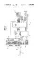
- FIG. 1is a diagram of a handpiece in circuit with a portion of known prior art system which includes a control logic state generator in circuit with a control logic module and a control and display panel for controlling and displaying various system operations;
- FIG. 2is a logic table for explaining the invention where FIG. 2A is a table of alternative handpieces and FIG. 2B shows a routine of interrogations for a handpiece connected to a logic circuit;
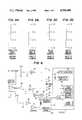
- FIG. 3shows alternative handpiece prewiring alternatives to cooperate with the circuit of FIG. 4 to achieve the control and display shown in FIG. 2;
- FIG. 4is a diagram of a prewired handpiece connector cooperating with a logic control circuit for providing display and control output signal for implementing the interrogation routine of FIG. 2.
- FIG. 1a portion of a system known to the art is shown which includes a handpiece designated generally by the reference numeral 10 and including a tip 11 capable of vibration at an amplitude controlled by a control system shown generally at 12 as determined by a control logic state generator 13 and a control logic circuit 14 connected to a control panel 15.
- the handpiece 10is connected through a cable 17 to a pin 18 inserted in a jack 19.
- the handpiece cable connectiondetermined by the pin 18 and the jack 19, cooperates with the state generator circuit 13 to provide a control signal 20 to the control logic circuit 14 indicating the presence of a handpiece.
- a control signal 20is generated which permits enablement of system operations, such as cooling, flow of irrigation fluid, suction pressure, vibration, and review of stroke amplitude under the influence of a feedback signal designated generally by the reference numeral 21, as is known in the art.
- command switches 22 for commanding irrigation, vibration, and system operationare provided which cooperate with the system state generator 13 to provide control signals 20 to the control logic circuit 14 for enabling operation of such systems 21 in the system 12.
- the control panel 15further includes indicators 23 indicating the presence of irrigation, suction, cooling, operation, and other parameters such as stroke vibration through the use, for example, of a meter or bar graph.
- the system of FIG. 1has worked satisfactorily to control the operation of a handpiece 10 requiring the delivery of a particular ultrasonic frequency to the tip 11 with its predetermined maximum stroke amplitude under the influence of a foot switch 24.
- FIGS. 2-4diagrammatically indicates a handpiece connector 31 which cooperates with a logic control circuit 33 for providing such an interrogation and appropriate control signals.
- FIG. 2Ais a morphology chart showing representative alternatives for the handpiece 31.
- the handpiecemay be a Type A device, such as a straight or standard handpiece, or it may be a Type B device such as an angled handpiece.
- the selected handpiece 31may be larger (i.e. a standard handpiece), requiring a lower ultrasonic resonant frequency or it may be smaller, requiring a higher ultrasonic resonant frequency.
- FIG. 2Bindicates a routine for interrogation into the alternatives of FIG. 2A as to whether the handpiece is a standard, straight (Type A) handpiece or an angled (Type B) handpiece, and whether it is a larger handpiece requiring a lower operating frequency or a smaller handpiece requiring a larger operating frequency.
- the interrogation routine of FIG. 2Bis exemplary and such interrogations could be expanded for other characteristics of the handpiece which might influence operations of the overall system.
- the first interrogation in step 42is whether a handpiece is connected. If no handpiece is connected, a display on the control panel 15 is inhibited in step 43 and, alternatively, system operations are inhibited in step 44 because of the absence of a handpiece, or an improper or incomplete connection.
- the systemmay interrogate whether the handpiece is a Type A handpiece, such as a straight or standard handpiece, or a Type B handpiece, such as an angled handpiece in step 46. If a Type A handpiece is inserted, a type A handpiece is indicated on a control panel in step 47; similarly, if a Type B handpiece has been connected, a type B handpiece is indicated on the control panel in step 48. Consistent with an indication of the type of handpiece in either of steps 47 and 48, the system may also be controlled with a logic signal for operations pertinent to the type of handpiece selected as in steps 49 and 50.
- a Type A handpiecesuch as a straight or standard handpiece
- a Type B handpiecesuch as an angled handpiece in step 46. If a Type A handpiece is inserted, a type A handpiece is indicated on a control panel in step 47; similarly, if a Type B handpiece has been connected, a type B handpiece is indicated on the control panel in step 48. Consistent with an indication of
- a control signal indicative of a Type A handpiecemay also be used to control system logic and parameters of the operating systems depending on system logic for operations consistent with a Type A handpiece.
- a logical signal indicating the presence of a Type B handpiece as in step 48may also be used to control system operations in step 50 of parameters in a manner consistent with the presence of a Type B handpiece.
- step 52the system 33 interrogates whether the handpiece 31 is a larger handpiece or a smaller handpiece. If the handpiece is a larger handpiece, a lower frequency vibration signal is indicated in step 53 consistent with the presence of a larger handpiece, and controlled in step 55. Conversely, if a smaller handpiece is present, step 54 indicates the presence of a smaller handpiece, requiring a higher control frequency, and the required higher frequency is controlled in step 56.
- a lower frequency signalis indicated in step 55, as in the case of a larger handpiece, the higher frequency signal may also be inhibited by the control signal in step 53. Conversely, the lower frequency signal may be inhibited in step 54, where a higher frequency signal is indicated for a smaller handpiece.
- FIG. 3Aindicates alternative connections for the handpiece which is connected to the logic circuit of FIG. 4.
- the pins on the handpiece labeled H and Grespectively are connected and no connections are provided between pin G and either of the pins labeled A and D.
- FIG. 3Bindicates the pin connections on a straight smaller handpiece
- FIG. 3Cindicates the pin connections for an angled larger handpiece
- FIG. 3Dindicate the connections for an angled, smaller handpiece. It will be appreciated in understanding this logic scheme that four alternatives are provided involving connections H, G H, G, D; H, G, A; and H, G, A, D, where pins H and G are always connected to trigger a handpiece presence signal in the circuit of FIG. 4.
- FIG. 4illustrates an appropriate logic circuit 33 for sensing the presence of a handpiece connector 31 and interrogating along the lines indicated in FIGS. 2A and 2B.
- the pins H and Gare connected, while the pins A and D are open (FIG. 3A).
- the connection between pins H and Geffectively grounds the input to a trigger 61 providing a high output signal from trigger 61 thus provided to the logic control circuit to the state generator 13 and control logic circuit 14 to indicate the presence of a handpiece to enable operations.
- the output from the inverter 62is a logical low providing a 12 volt source across a pump relay 63 to activate a cooling motor pump to start cooling operations.
- a circuit of the inverter 62 and the relay 63is exemplary of the types of sub-systems in the ultrasonic aspiration system which can be controlled by an output logic signal indicating the presence of a handpiece connector.
- the absence of a connection to pin Ameans that a logical high signal is provided to the trigger 64 which is inverted to provide a logical low at the output of a trigger 65.
- the presence of a high signal at the output of the trigger 61actuates a transistor switch 66 so that the high signal is provided to the input of the trigger 67, the output of which is inverted to a logical low which, when provided to an indicator on a control panel 15 indicates the presence of a standard handpiece.
- the low logical output from the trigger 64becomes a logical high at the output of the trigger 68 which inhibits actuation of a lamp 72 on the control panel 15 so that an indicator indicating the presence of an angled handpiece is inhibited.
- the display panel 23shows the presence of a standard handpiece by an indicator 71 and inhibits a signal indicating the presence of an angled handpiece on the indicator 72.
- an absence of a connection at pin Aprovides a logical high to the trigger 64, the output of which is a logical low.
- the logical low at the output of the trigger 64is provided to the input of the trigger 65, the output of which is the logical high. That logical high from the output of trigger 65 is provided on lead 74 to a logic module 75 in the control circuits 13 and 14 for use as desired indicating the presence of a standard size, straight handpiece requiring a lower frequency signal.
- a logical highis provided to the input of the trigger 80 whose output is a logical low which is inverted by the inverter 81 to provide a logical high at the output thereof.
- a logical high at the output of the inverter 81fails to switch the generator 82 at its lower frequency so that the lower frequency is provided to the standard lower frequency handpiece as is necessary. That control signal may also be used, if needed, in a frequency control module 84 for controlling other frequency dependent parameters.
- the logic circuit of FIG. 4operates similarly to indicate the presence of a handpiece (i.e. any handpiece) and to actuate a standard handpiece display on the indicator 71 on the panel 15.
- a logical lowis provided to the trigger 80 which becomes a logical high at its output for subsequent inversion to a logical low by the inverter 81.
- a logical low provided to the generator control circuit 82causes the relay to actuate to switch the generator from its lower normal operating frequency to a higher operating frequency needed for the smaller handpiece.
- a display of the frequency generatedmay also be provided on the display panel utilizing that same signal, through the circuit 84.
- FIG. 3CWhen an angled larger handpiece requiring a smaller frequency is connected (FIG. 3C), it is prewired with connections between the H, G, and A pins with the D pin left open. Thereafter, the logic circuit of FIG. 4 operates to enable a signal indicating the presence of an angled handpiece on indicator 72, to avoid switching the generator from its normal lower frequency signal, and to inhibit illumination of the standard handpiece display 71 on the control panel, while indicating the presence of a handpiece on the indicator 59.
Landscapes
- Health & Medical Sciences (AREA)
- Surgery (AREA)
- Engineering & Computer Science (AREA)
- Life Sciences & Earth Sciences (AREA)
- Biomedical Technology (AREA)
- Nuclear Medicine, Radiotherapy & Molecular Imaging (AREA)
- Vascular Medicine (AREA)
- Orthopedic Medicine & Surgery (AREA)
- Mechanical Engineering (AREA)
- Heart & Thoracic Surgery (AREA)
- Medical Informatics (AREA)
- Molecular Biology (AREA)
- Animal Behavior & Ethology (AREA)
- General Health & Medical Sciences (AREA)
- Public Health (AREA)
- Veterinary Medicine (AREA)
- Surgical Instruments (AREA)
Abstract
Description
Claims (20)
Priority Applications (1)
| Application Number | Priority Date | Filing Date | Title |
|---|---|---|---|
| US06/849,893US4768496A (en) | 1986-04-09 | 1986-04-09 | Handpiece interlock and logic control for ultrasonic surgical system |
Applications Claiming Priority (1)
| Application Number | Priority Date | Filing Date | Title |
|---|---|---|---|
| US06/849,893US4768496A (en) | 1986-04-09 | 1986-04-09 | Handpiece interlock and logic control for ultrasonic surgical system |
Publications (1)
| Publication Number | Publication Date |
|---|---|
| US4768496Atrue US4768496A (en) | 1988-09-06 |
Family
ID=25306774
Family Applications (1)
| Application Number | Title | Priority Date | Filing Date |
|---|---|---|---|
| US06/849,893Expired - LifetimeUS4768496A (en) | 1986-04-09 | 1986-04-09 | Handpiece interlock and logic control for ultrasonic surgical system |
Country Status (1)
| Country | Link |
|---|---|
| US (1) | US4768496A (en) |
Cited By (43)
| Publication number | Priority date | Publication date | Assignee | Title |
|---|---|---|---|---|
| US4840066A (en)* | 1988-06-27 | 1989-06-20 | Ndt Instruments, Inc. | Ultrasonic thickness gauge having automatic transducer recognition and parameter optimization and method thereof |
| WO1991011965A1 (en)* | 1990-02-06 | 1991-08-22 | Advanced Osseous Technologies | Apparatus for implantation and extraction of prostheses |
| JPH04158856A (en)* | 1990-10-23 | 1992-06-01 | Olympus Optical Co Ltd | Ultrasonic processor |
| US5139509A (en)* | 1989-08-25 | 1992-08-18 | Site Microsurgical Systems, Inc. | Phacoemulsification system with handpiece simulator |
| JPH04231037A (en)* | 1990-12-27 | 1992-08-19 | Sumitomo Bakelite Co Ltd | Surgical apparatus |
| US5184605A (en)* | 1991-01-31 | 1993-02-09 | Excel Tech Ltd. | Therapeutic ultrasound generator with radiation dose control |
| WO1993005713A1 (en)* | 1991-09-13 | 1993-04-01 | Cardiovascular Imaging Systems, Inc. | Ultrasonic imaging catheter with identification means |
| US5209719A (en)* | 1990-01-23 | 1993-05-11 | Urcan Medical Ltd. | Ultrasonic recanalization system |
| US5318570A (en)* | 1989-01-31 | 1994-06-07 | Advanced Osseous Technologies, Inc. | Ultrasonic tool |
| US5324297A (en)* | 1989-01-31 | 1994-06-28 | Advanced Osseous Technologies, Inc. | Ultrasonic tool connector |
| US5330481A (en)* | 1989-01-31 | 1994-07-19 | Advanced Osseous Technologies, Inc. | Apparatus for implantation and extraction of osteal prostheses |
| US5344395A (en)* | 1989-11-13 | 1994-09-06 | Scimed Life Systems, Inc. | Apparatus for intravascular cavitation or delivery of low frequency mechanical energy |
| US5382251A (en)* | 1989-01-31 | 1995-01-17 | Biomet, Inc. | Plug pulling method |
| US5391144A (en)* | 1990-02-02 | 1995-02-21 | Olympus Optical Co., Ltd. | Ultrasonic treatment apparatus |
| US5425704A (en)* | 1989-04-28 | 1995-06-20 | Olympus Optical Co., Ltd. | Apparatus for generating ultrasonic oscillation |
| US5460595A (en)* | 1993-06-01 | 1995-10-24 | Dynatronics Laser Corporation | Multi-frequency ultrasound therapy systems and methods |
| US5542425A (en)* | 1994-12-20 | 1996-08-06 | Acuson Corporation | Apparatus and method for preventing contact damage in electrical equipment |
| WO1998014129A1 (en)* | 1996-09-30 | 1998-04-09 | Minnesota Mining And Manufacturing Company | Powered surgical instruments and control unit |
| US5754016A (en)* | 1996-09-18 | 1998-05-19 | Dentsply Research & Development Corp | Method of continuous control of tip vibration in a dental scalar system |
| US5813404A (en)* | 1995-10-20 | 1998-09-29 | Aspect Medical Systems, Inc. | Electrode connector system |
| US6053871A (en)* | 1997-01-21 | 2000-04-25 | William Cook Australia Pty. Ltd | Calibrated hollow probe for use with ultrasound imaging |
| EP0951921A3 (en)* | 1998-04-24 | 2000-05-03 | Indigo Medical, Incorporated | Human tissue energy application system |
| JP3342090B2 (en) | 1993-04-12 | 2002-11-05 | オリンパス光学工業株式会社 | Electrosurgical equipment |
| US6602227B1 (en)* | 1998-09-25 | 2003-08-05 | Sherwood Services Ag | Surgical system console |
| US20030199794A1 (en)* | 2002-04-17 | 2003-10-23 | Olympus Optical Co., Ltd. | Ultrasonic operating apparatus |
| US20060047330A1 (en)* | 2004-09-02 | 2006-03-02 | Whatcott Gary L | Dynamically distributing power of a light beam for use in light therapy |
| WO2007019624A1 (en)* | 2005-08-15 | 2007-02-22 | Resmed Ltd | Cpap systems |
| US20070208396A1 (en)* | 2006-03-03 | 2007-09-06 | Gary Whatcott | Systems and methods for providing a dynamic light pad |
| US20070208289A1 (en)* | 2006-03-03 | 2007-09-06 | Jay Walther | Systems and methods for providing light therapy traction |
| US20080173305A1 (en)* | 2007-01-11 | 2008-07-24 | Resmed Limited | Fastenable conduit for breathable gas delivery |
| US20090240272A1 (en)* | 2008-03-20 | 2009-09-24 | Medtronic Xomed, Inc. | Control For A Powered Surgical Instrument |
| US20110139154A1 (en)* | 2005-12-21 | 2011-06-16 | Resmed Limited | Identification system and method for mask and ventilator components |
| US20110177474A1 (en)* | 2008-03-18 | 2011-07-21 | Hu-Friedy Mfg. Co., Inc | Handpiece for a Magnetostrictive Power Generator |
| US9162035B2 (en) | 2005-03-01 | 2015-10-20 | Resmed Limited | Recognition system for an apparatus that delivers breathable gas to a patient |
| US10391210B2 (en) | 2016-05-20 | 2019-08-27 | Integra Lifesciences Nr Ireland Limited | Ergonomic tubing attachment for medical apparatus |
| US10687840B1 (en) | 2016-11-17 | 2020-06-23 | Integra Lifesciences Nr Ireland Limited | Ultrasonic transducer tissue selectivity |
| US10751104B2 (en) | 2014-10-30 | 2020-08-25 | Stryker Far East, Inc. | Surgical tool with an aseptic power module that enters a specific operating state based on the type of handpiece to which the power module is attached |
| US11173327B2 (en) | 2016-04-25 | 2021-11-16 | Integra Lifesciences Enterprises, Lllp | Flue for ultrasonic aspiration surgical horn |
| US11191553B2 (en) | 2016-06-13 | 2021-12-07 | Integra Lifesciences Enterprises, Lllp | Connector for surgical handpiece |
| US11284915B2 (en) | 2016-11-16 | 2022-03-29 | Integra Lifesciences Enterprises, Lllp | Ultrasonic surgical handpiece having a thermal diffuser |
| US11759271B2 (en) | 2017-04-28 | 2023-09-19 | Stryker Corporation | System and method for indicating mapping of console-based surgical systems |
| US11944278B2 (en) | 2011-12-16 | 2024-04-02 | Stryker Corporation | Cassette for collecting a tissue sample with a medical fluid collection system |
| US12109352B2 (en) | 2016-05-20 | 2024-10-08 | Integra Lifesciences Enterprises, Lllp | Ergonomic tubing attachment for medical apparatus |
Citations (1)
| Publication number | Priority date | Publication date | Assignee | Title |
|---|---|---|---|---|
| US4407298A (en)* | 1981-07-16 | 1983-10-04 | Critikon Inc. | Connector for thermodilution catheter |
- 1986
- 1986-04-09USUS06/849,893patent/US4768496A/ennot_activeExpired - Lifetime
Patent Citations (1)
| Publication number | Priority date | Publication date | Assignee | Title |
|---|---|---|---|---|
| US4407298A (en)* | 1981-07-16 | 1983-10-04 | Critikon Inc. | Connector for thermodilution catheter |
Cited By (73)
| Publication number | Priority date | Publication date | Assignee | Title |
|---|---|---|---|---|
| US4840066A (en)* | 1988-06-27 | 1989-06-20 | Ndt Instruments, Inc. | Ultrasonic thickness gauge having automatic transducer recognition and parameter optimization and method thereof |
| US5324297A (en)* | 1989-01-31 | 1994-06-28 | Advanced Osseous Technologies, Inc. | Ultrasonic tool connector |
| US5382251A (en)* | 1989-01-31 | 1995-01-17 | Biomet, Inc. | Plug pulling method |
| US5330481A (en)* | 1989-01-31 | 1994-07-19 | Advanced Osseous Technologies, Inc. | Apparatus for implantation and extraction of osteal prostheses |
| US5318570A (en)* | 1989-01-31 | 1994-06-07 | Advanced Osseous Technologies, Inc. | Ultrasonic tool |
| US5425704A (en)* | 1989-04-28 | 1995-06-20 | Olympus Optical Co., Ltd. | Apparatus for generating ultrasonic oscillation |
| US5139509A (en)* | 1989-08-25 | 1992-08-18 | Site Microsurgical Systems, Inc. | Phacoemulsification system with handpiece simulator |
| US5344395A (en)* | 1989-11-13 | 1994-09-06 | Scimed Life Systems, Inc. | Apparatus for intravascular cavitation or delivery of low frequency mechanical energy |
| US5209719A (en)* | 1990-01-23 | 1993-05-11 | Urcan Medical Ltd. | Ultrasonic recanalization system |
| US5836897A (en)* | 1990-02-02 | 1998-11-17 | Olympus Optical Co., Ltd. | Ultrasonic treatment apparatus |
| US5391144A (en)* | 1990-02-02 | 1995-02-21 | Olympus Optical Co., Ltd. | Ultrasonic treatment apparatus |
| US5688235A (en)* | 1990-02-02 | 1997-11-18 | Olympus Optical Co., Ltd. | Ultrasonic treatment apparatus |
| US5284484A (en)* | 1990-02-06 | 1994-02-08 | Advanced Osseous Technologies, Inc. | Apparatus for implantation and extraction of osteal prostheses |
| US5045054A (en)* | 1990-02-06 | 1991-09-03 | Advanced Osseous Technologies Inc. | Apparatus for implantation and extraction of osteal prostheses |
| WO1991011965A1 (en)* | 1990-02-06 | 1991-08-22 | Advanced Osseous Technologies | Apparatus for implantation and extraction of prostheses |
| JPH04158856A (en)* | 1990-10-23 | 1992-06-01 | Olympus Optical Co Ltd | Ultrasonic processor |
| JP2578250B2 (en) | 1990-10-23 | 1997-02-05 | オリンパス光学工業株式会社 | Ultrasonic treatment equipment |
| JPH04231037A (en)* | 1990-12-27 | 1992-08-19 | Sumitomo Bakelite Co Ltd | Surgical apparatus |
| US5184605A (en)* | 1991-01-31 | 1993-02-09 | Excel Tech Ltd. | Therapeutic ultrasound generator with radiation dose control |
| US5209235A (en)* | 1991-09-13 | 1993-05-11 | Cardiovascular Imaging Systems, Inc. | Ultrasonic imaging catheter assembly and method for identification of the same |
| WO1993005713A1 (en)* | 1991-09-13 | 1993-04-01 | Cardiovascular Imaging Systems, Inc. | Ultrasonic imaging catheter with identification means |
| JP3342090B2 (en) | 1993-04-12 | 2002-11-05 | オリンパス光学工業株式会社 | Electrosurgical equipment |
| US5460595A (en)* | 1993-06-01 | 1995-10-24 | Dynatronics Laser Corporation | Multi-frequency ultrasound therapy systems and methods |
| WO1996027358A1 (en)* | 1993-06-01 | 1996-09-12 | Dynatronics Laser Corporation | Multi-frequency ultrasound therapy systems and methods |
| US5542425A (en)* | 1994-12-20 | 1996-08-06 | Acuson Corporation | Apparatus and method for preventing contact damage in electrical equipment |
| US6236874B1 (en) | 1995-10-20 | 2001-05-22 | Aspect Medical Systems, Inc. | Electrode connector system |
| US5813404A (en)* | 1995-10-20 | 1998-09-29 | Aspect Medical Systems, Inc. | Electrode connector system |
| US5754016A (en)* | 1996-09-18 | 1998-05-19 | Dentsply Research & Development Corp | Method of continuous control of tip vibration in a dental scalar system |
| WO1998014129A1 (en)* | 1996-09-30 | 1998-04-09 | Minnesota Mining And Manufacturing Company | Powered surgical instruments and control unit |
| US6053871A (en)* | 1997-01-21 | 2000-04-25 | William Cook Australia Pty. Ltd | Calibrated hollow probe for use with ultrasound imaging |
| EP0951921A3 (en)* | 1998-04-24 | 2000-05-03 | Indigo Medical, Incorporated | Human tissue energy application system |
| AU754594B2 (en)* | 1998-04-24 | 2002-11-21 | Indigo Medical, Incorporated | Energy application system with ancillary information exchange capability, energy applicator, and methods associated therewith |
| US6602227B1 (en)* | 1998-09-25 | 2003-08-05 | Sherwood Services Ag | Surgical system console |
| US20040068208A1 (en)* | 1998-09-25 | 2004-04-08 | Cimino William Wayne | Surgical system console |
| US7204825B2 (en) | 1998-09-25 | 2007-04-17 | Integra Lifesciences (Ireland) Ltd. | Surgical system console |
| US20030199794A1 (en)* | 2002-04-17 | 2003-10-23 | Olympus Optical Co., Ltd. | Ultrasonic operating apparatus |
| US20060047330A1 (en)* | 2004-09-02 | 2006-03-02 | Whatcott Gary L | Dynamically distributing power of a light beam for use in light therapy |
| US7374569B2 (en) | 2004-09-02 | 2008-05-20 | Dynatronics, Corporation | Dynamically distributing power of a light beam for use in light therapy |
| US9162035B2 (en) | 2005-03-01 | 2015-10-20 | Resmed Limited | Recognition system for an apparatus that delivers breathable gas to a patient |
| US10279134B2 (en) | 2005-03-01 | 2019-05-07 | Resmed Limited | Recognition system for an apparatus that delivers breathable gas to a patient |
| WO2007019624A1 (en)* | 2005-08-15 | 2007-02-22 | Resmed Ltd | Cpap systems |
| US9182062B2 (en) | 2005-08-15 | 2015-11-10 | Resmed Limited | CPAP systems |
| US10058666B2 (en) | 2005-08-15 | 2018-08-28 | Resmed Limited | CPAP systems |
| US8316848B2 (en) | 2005-08-15 | 2012-11-27 | Resmed Limited | CPAP systems |
| US20110139154A1 (en)* | 2005-12-21 | 2011-06-16 | Resmed Limited | Identification system and method for mask and ventilator components |
| US8939147B2 (en) | 2005-12-21 | 2015-01-27 | Resmed Limited | Identification system and method for mask and ventilator components |
| US20070208289A1 (en)* | 2006-03-03 | 2007-09-06 | Jay Walther | Systems and methods for providing light therapy traction |
| US20100094190A1 (en)* | 2006-03-03 | 2010-04-15 | Jay Walther | Systems and methods for providing light therapy traction |
| US20070208396A1 (en)* | 2006-03-03 | 2007-09-06 | Gary Whatcott | Systems and methods for providing a dynamic light pad |
| US8273046B2 (en) | 2006-03-03 | 2012-09-25 | Dynatronics Corporation | Systems and methods for providing light therapy traction |
| US20080173305A1 (en)* | 2007-01-11 | 2008-07-24 | Resmed Limited | Fastenable conduit for breathable gas delivery |
| US8312875B2 (en) | 2007-01-11 | 2012-11-20 | Resmed Limited | Fastenable conduit for breathable gas delivery |
| US9108227B2 (en) | 2007-01-11 | 2015-08-18 | Redmed Limited | Fastenable conduit for breathable gas delivery |
| US8678820B2 (en)* | 2008-03-18 | 2014-03-25 | Hu-Friedy Mfg. Co., LLC. | Handpiece for a magnetostrictive power generator |
| US20110177474A1 (en)* | 2008-03-18 | 2011-07-21 | Hu-Friedy Mfg. Co., Inc | Handpiece for a Magnetostrictive Power Generator |
| US8197501B2 (en) | 2008-03-20 | 2012-06-12 | Medtronic Xomed, Inc. | Control for a powered surgical instrument |
| US8545527B2 (en) | 2008-03-20 | 2013-10-01 | Medtronic Xomed, Inc. | Control for a powered surgical instrument |
| US20090240272A1 (en)* | 2008-03-20 | 2009-09-24 | Medtronic Xomed, Inc. | Control For A Powered Surgical Instrument |
| US11944278B2 (en) | 2011-12-16 | 2024-04-02 | Stryker Corporation | Cassette for collecting a tissue sample with a medical fluid collection system |
| US11364064B2 (en) | 2014-10-30 | 2022-06-21 | Stryker Far East, Inc. | Surgical tool with an aseptic power module that enters a specific state based on the type of handpiece to which the power module is attached |
| US10751104B2 (en) | 2014-10-30 | 2020-08-25 | Stryker Far East, Inc. | Surgical tool with an aseptic power module that enters a specific operating state based on the type of handpiece to which the power module is attached |
| US11738215B2 (en) | 2016-04-25 | 2023-08-29 | Integra LifeSciences Enterprises, LLP | Flue for ultrasonic aspiration surgical horn |
| US11173327B2 (en) | 2016-04-25 | 2021-11-16 | Integra Lifesciences Enterprises, Lllp | Flue for ultrasonic aspiration surgical horn |
| US12138489B2 (en) | 2016-04-25 | 2024-11-12 | Integra Lifesciences Enterprises, Lllp | Flue for ultrasonic aspiration surgical horn |
| US10391210B2 (en) | 2016-05-20 | 2019-08-27 | Integra Lifesciences Nr Ireland Limited | Ergonomic tubing attachment for medical apparatus |
| US11612682B2 (en) | 2016-05-20 | 2023-03-28 | Integra Lifesciences Enterprises, Lllp | Ergonomic tubing attachment for medical apparatus |
| US12109352B2 (en) | 2016-05-20 | 2024-10-08 | Integra Lifesciences Enterprises, Lllp | Ergonomic tubing attachment for medical apparatus |
| US11191553B2 (en) | 2016-06-13 | 2021-12-07 | Integra Lifesciences Enterprises, Lllp | Connector for surgical handpiece |
| US11284915B2 (en) | 2016-11-16 | 2022-03-29 | Integra Lifesciences Enterprises, Lllp | Ultrasonic surgical handpiece having a thermal diffuser |
| US10687840B1 (en) | 2016-11-17 | 2020-06-23 | Integra Lifesciences Nr Ireland Limited | Ultrasonic transducer tissue selectivity |
| US11864785B1 (en) | 2016-11-17 | 2024-01-09 | Integra Lifesciences Enterprises, Lllp | Ultrasonic transducer tissue selectivity |
| US12193697B2 (en) | 2016-11-17 | 2025-01-14 | Integra Lifesciences Enterprises, Lllp | Ultrasonic transducer tissue selectivity |
| US11759271B2 (en) | 2017-04-28 | 2023-09-19 | Stryker Corporation | System and method for indicating mapping of console-based surgical systems |
Similar Documents
| Publication | Publication Date | Title |
|---|---|---|
| US4768496A (en) | Handpiece interlock and logic control for ultrasonic surgical system | |
| US11147611B2 (en) | Relay device and ultrasonic-surgical and electrosurgical system | |
| US5968007A (en) | Power-limit control for ultrasonic surgical instrument | |
| US6045527A (en) | Detection of ophthalmic surgical handpiece using shorting bar | |
| JP3905482B2 (en) | Surgery system | |
| US20020156466A1 (en) | Surgical system | |
| US20030199794A1 (en) | Ultrasonic operating apparatus | |
| US20090264881A1 (en) | Ultrasonic surgical system | |
| EP3927255B1 (en) | System for driving an ultrasonic device | |
| AU5390096A (en) | Motor controlled surgical system and method having positional control | |
| JP2003521954A (en) | Surgical instrument console | |
| CN101502460A (en) | Method of controlling a surgical system based on a load on the cutting tip of a handpiece | |
| JP2001112768A (en) | Liquid supply/collection device | |
| JP2578250B2 (en) | Ultrasonic treatment equipment | |
| US8574175B2 (en) | Treatment apparatus and operation system | |
| CN112535517A (en) | Two-wire system ultrasonic scalpel system with multiple control inputs | |
| JP2002200094A (en) | Ultrasonic operative instrument | |
| JP4040914B2 (en) | Ultrasonic surgical device | |
| US20220227017A1 (en) | Method for vibrating handpiece-type high-frequency vibration apparatus | |
| JP3174096B2 (en) | Surgical surgery device | |
| JP3302101B2 (en) | Ultrasound therapy equipment | |
| JP3192340B2 (en) | Ultrasound surgery device | |
| JPH04231037A (en) | Surgical apparatus | |
| US20050187539A1 (en) | Electric operation system | |
| US6077272A (en) | Detection of intraocular surgical scissors |
Legal Events
| Date | Code | Title | Description |
|---|---|---|---|
| AS | Assignment | Owner name:COOPER LASERSONICS, INC., 88 HAMILTON AVENUE, STAM Free format text:ASSIGNMENT OF ASSIGNORS INTEREST.;ASSIGNORS:KREIZMAN, ALEXANDER;PUIAM, CHANA;REEL/FRAME:004538/0320 Effective date:19860408 | |
| AS | Assignment | Owner name:MANUFACTURERS HANOVER TRUST COMPANY Free format text:MORTGAGE;ASSIGNOR:COOPER LASERSONICS, INC.;REEL/FRAME:004645/0615 Effective date:19861101 | |
| AS | Assignment | Owner name:COOPER LASERSONICS, INC., A DE. CORP. Free format text:AGENT HEREBY RELEASE ALL INTEREST IN SAID SECURITY AGREEMENT-RECORDED DEC. 15, 1986 - REEL 4645, FRAMES 615-623;ASSIGNOR:MANUFACTURERS HANOVER TRUST COMPANY;REEL/FRAME:004801/0671 Effective date:19870609 Owner name:COOPER LASERSONICS, INC., A DE. CORP.,STATELESS Free format text:AGENT HEREBY RELEASE ALL INTEREST IN SAID SECURITY AGREEMENT-RECORDED DEC. 15, 1986 - REEL 4645, FRAMES 615-623;ASSIGNOR:MANUFACTURERS HANOVER TRUST COMPANY;REEL/FRAME:004801/0671 Effective date:19870609 | |
| STCF | Information on status: patent grant | Free format text:PATENTED CASE | |
| AS | Assignment | Owner name:CAVITRON, INC., CONNECTICUT Free format text:ASSIGNMENT OF ASSIGNORS INTEREST.;ASSIGNOR:COOPER LASERSONICS, INC.;REEL/FRAME:005173/0988 Effective date:19880426 | |
| AS | Assignment | Owner name:VALLEYLAB ULTRASONIC SURGICAL PRODUCTS, INC. Free format text:CHANGE OF NAME;ASSIGNOR:V-CUSA, INC.;REEL/FRAME:005348/0080 Effective date:19900301 Owner name:VALLEYLAB, INC., A CORP. OF CO Free format text:MERGER;ASSIGNOR:VALLEYLAB ULTRASONIC SURGICAL PORDUCTS, INC.;REEL/FRAME:005348/0083 Effective date:19900301 Owner name:V-CUSA, INC. Free format text:CHANGE OF NAME;ASSIGNOR:CAVITRON, INC.;REEL/FRAME:005348/0077 Effective date:19900301 | |
| FEPP | Fee payment procedure | Free format text:PAYOR NUMBER ASSIGNED (ORIGINAL EVENT CODE: ASPN); ENTITY STATUS OF PATENT OWNER: LARGE ENTITY | |
| FPAY | Fee payment | Year of fee payment:4 | |
| FPAY | Fee payment | Year of fee payment:8 | |
| AS | Assignment | Owner name:SHERWOOD SERVICES AG, SWITZERLAND Free format text:ASSIGNMENT OF ASSIGNORS INTEREST;ASSIGNOR:VALLEYLAB INC;REEL/FRAME:010052/0056 Effective date:19980930 | |
| FPAY | Fee payment | Year of fee payment:12 |