US4768276A - Method of applying a fastener to sheet material - Google Patents
Method of applying a fastener to sheet materialDownload PDFInfo
- Publication number
- US4768276A US4768276AUS07/059,810US5981087AUS4768276AUS 4768276 AUS4768276 AUS 4768276AUS 5981087 AUS5981087 AUS 5981087AUS 4768276 AUS4768276 AUS 4768276A
- Authority
- US
- United States
- Prior art keywords
- body member
- rivet
- button
- recess
- opening
- Prior art date
- Legal status (The legal status is an assumption and is not a legal conclusion. Google has not performed a legal analysis and makes no representation as to the accuracy of the status listed.)
- Expired - Lifetime
Links
- 239000000463materialSubstances0.000titleclaimsabstractdescription110
- 238000000034methodMethods0.000titleclaimsdescription12
- 230000037303wrinklesEffects0.000claimsabstract3
- 230000002093peripheral effectEffects0.000claimsdescription12
- 239000004744fabricSubstances0.000description4
- 230000004048modificationEffects0.000description4
- 238000012986modificationMethods0.000description4
- 238000009434installationMethods0.000description2
- 238000010276constructionMethods0.000description1
- 230000000694effectsEffects0.000description1
- 239000013013elastic materialSubstances0.000description1
- 230000000284resting effectEffects0.000description1
- 230000000717retained effectEffects0.000description1
- 229910052709silverInorganic materials0.000description1
- 239000004332silverSubstances0.000description1
- 230000001360synchronised effectEffects0.000description1
- 229920002994synthetic fiberPolymers0.000description1
Images

Classifications
- A—HUMAN NECESSITIES
- A41—WEARING APPAREL
- A41H—APPLIANCES OR METHODS FOR MAKING CLOTHES, e.g. FOR DRESS-MAKING OR FOR TAILORING, NOT OTHERWISE PROVIDED FOR
- A41H37/00—Machines, appliances or methods for setting fastener-elements on garments
- A41H37/10—Setting buttons
- A—HUMAN NECESSITIES
- A41—WEARING APPAREL
- A41H—APPLIANCES OR METHODS FOR MAKING CLOTHES, e.g. FOR DRESS-MAKING OR FOR TAILORING, NOT OTHERWISE PROVIDED FOR
- A41H37/00—Machines, appliances or methods for setting fastener-elements on garments
- Y—GENERAL TAGGING OF NEW TECHNOLOGICAL DEVELOPMENTS; GENERAL TAGGING OF CROSS-SECTIONAL TECHNOLOGIES SPANNING OVER SEVERAL SECTIONS OF THE IPC; TECHNICAL SUBJECTS COVERED BY FORMER USPC CROSS-REFERENCE ART COLLECTIONS [XRACs] AND DIGESTS
- Y10—TECHNICAL SUBJECTS COVERED BY FORMER USPC
- Y10T—TECHNICAL SUBJECTS COVERED BY FORMER US CLASSIFICATION
- Y10T29/00—Metal working
- Y10T29/49—Method of mechanical manufacture
- Y10T29/49826—Assembling or joining
- Y10T29/49833—Punching, piercing or reaming part by surface of second part
- Y—GENERAL TAGGING OF NEW TECHNOLOGICAL DEVELOPMENTS; GENERAL TAGGING OF CROSS-SECTIONAL TECHNOLOGIES SPANNING OVER SEVERAL SECTIONS OF THE IPC; TECHNICAL SUBJECTS COVERED BY FORMER USPC CROSS-REFERENCE ART COLLECTIONS [XRACs] AND DIGESTS
- Y10—TECHNICAL SUBJECTS COVERED BY FORMER USPC
- Y10T—TECHNICAL SUBJECTS COVERED BY FORMER US CLASSIFICATION
- Y10T29/00—Metal working
- Y10T29/49—Method of mechanical manufacture
- Y10T29/49826—Assembling or joining
- Y10T29/49863—Assembling or joining with prestressing of part
- Y10T29/4987—Elastic joining of parts
- Y—GENERAL TAGGING OF NEW TECHNOLOGICAL DEVELOPMENTS; GENERAL TAGGING OF CROSS-SECTIONAL TECHNOLOGIES SPANNING OVER SEVERAL SECTIONS OF THE IPC; TECHNICAL SUBJECTS COVERED BY FORMER USPC CROSS-REFERENCE ART COLLECTIONS [XRACs] AND DIGESTS
- Y10—TECHNICAL SUBJECTS COVERED BY FORMER USPC
- Y10T—TECHNICAL SUBJECTS COVERED BY FORMER US CLASSIFICATION
- Y10T29/00—Metal working
- Y10T29/49—Method of mechanical manufacture
- Y10T29/49826—Assembling or joining
- Y10T29/49947—Assembling or joining by applying separate fastener
- Y10T29/49948—Multipart cooperating fastener [e.g., bolt and nut]
- Y10T29/4995—Nonthreaded
- Y—GENERAL TAGGING OF NEW TECHNOLOGICAL DEVELOPMENTS; GENERAL TAGGING OF CROSS-SECTIONAL TECHNOLOGIES SPANNING OVER SEVERAL SECTIONS OF THE IPC; TECHNICAL SUBJECTS COVERED BY FORMER USPC CROSS-REFERENCE ART COLLECTIONS [XRACs] AND DIGESTS
- Y10—TECHNICAL SUBJECTS COVERED BY FORMER USPC
- Y10T—TECHNICAL SUBJECTS COVERED BY FORMER US CLASSIFICATION
- Y10T29/00—Metal working
- Y10T29/49—Method of mechanical manufacture
- Y10T29/49826—Assembling or joining
- Y10T29/49947—Assembling or joining by applying separate fastener
- Y10T29/49948—Multipart cooperating fastener [e.g., bolt and nut]
- Y10T29/49952—At least one part is nonmetallic
Definitions
- the inventionrelates to methods and apparatus for attaching two components of a fastener to a garment or to a compliant sheet of material in sandwich configuration without puckering or wrinkling the material.
- U.S. Pat. Nos. 2,071,507, 2,310,007, 4,309,806, and 4,454,650contains a number of methods and apparatus for applying a fastener member to sheet material that is maintained in a relatively taut or tensioned condition as the prongs pierce the material and are received in the fastener member.
- a snap fasteneris applied to an elastic sheet material in which the sheet material is stretched over an eyelet member, perforated at the tip after which the elastic material snaps down the post towards the base of the eyelet.
- U.S. Pat. No. 2,310,007has a plurality of clamps that attempt to maintain the material in position, but the material tends to give when the prongs penetrate therethrough, resulting in some puckering or wrinkling around the fastener element.
- a flexible circular member affixed to the socket memberengages the material and tends to urge the sheet material circumscribed thereby into a stretched position as the prong members penetrate the material.
- 4,454,650drives the upper component of the fastener through an opening in the table that is substantially larger than either the upper or lower component and unto a stationary lower component immediately beneath the fabric, which fabric is not held so as to be stretched taut over the opening.
- the prior art methods and apparatusare limited to frictionally holding a sheet of material in a given plane as shown in U.S. Pat. Nos. 2,310,007 and 4,309,806; or require deformation of an elastic sheet material that snaps into position once it is perforated as shown in U.S. Pat. No. 2,071,507; or drive the upper component and material onto a stationary lower component without the material being held in place as shown in U.S. Pat. No. 4,454,650.
- the subject inventionavoids wrinkling of the sheet material after the application of a fastener member thereto.
- the inventionis summarized as a method and apparatus for applying a fastener having a body member and a rivet member to compliant sheet material including an apertured member, having an opening therein coaxially aligned with first and second tool members, the inner peripheral wall of the apertured member being of substantially the same cross-sectional configuration as the body of the fastener, the opening of the apertured member being of a size large enough to accept the body of the fastener with the upper portion of the inner peripheral wall of the opening adapted to cooperate with the outer peripheral surface of the body of the fastener to capture the material therebetween and stretch the material taut over the bottom end of the body of the fastener such that a post member can pierce the material and be received within a recess in the bottom end of the body without wrinkling or puckering the material.
- An object of the inventionis an improved method and apparatus for applying a fastener element to a compliant sheet of material without wrinkling.
- Another object of the inventionis to confine the drawing or stretching of the sheet material during the setting operation to that part of the sheet material which is immediately adjacent the point at which the post pierces the material.
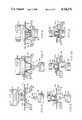
- FIG. 1is a diagrammatical view, partly in section, of the apparatus for applying a button and rivet to a sheet of compliant material just prior to the assembly operation;
- FIG. 2is a view similar to FIG. 1 and showing the apparatus during the initial application of the button and rivet to the sheet of material;
- FIG. 3is a view similar to FIG. 2 and showing the apparatus during the final step of application of the button and rivet to the sheet of material;
- FIG. 4is a perspective view, with a portion shown in section, of the annular member that captures the sheet material during application of the button and rivet thereto;
- FIG. 5is a perspective view of another embodiment of the button and rivet of the invention.
- FIG. 6is a view similar to FIG. 1 and showing another embodiment of the apparatus for applying a button and rivet to a thin sheet of compliant material just prior to the assembly operation;
- FIG. 7is a view similar to FIG. 6 and showing the apparatus during the initial application of the button and rivet to the sheet of material;
- FIG. 8is a view similar to FIG. 7 and showing the apparatus during the final step of application of the button and rivet to the sheet of material;
- FIG. 9is a view similar to FIG. 1 and showing still another embodiment of the apparatus for applying a post and stud of a snap fastener to a sheet of compliant material just prior to the assembly operation;
- FIG. 10is a view similar to FIG. 9 and showing the apparatus during the initial application of the post and stud to the sheet of material;
- FIG. 11is a view similar to FIG. 10 showing the apparatus during the final step of application of the post and stud to the sheet of material.
- the apparatus for applying a button and rivet to a sheet of material as embodied in the present inventionis illustrated and generally indicated at 10.
- the general details of the structure and operation of the complete apparatusis well known in the art, and one embodiment of such apparatus is shown and described in the patent to Schmidt, et al U.S. Pat. No. 3,803,698.
- FIG. 1there is shown a button fastener 12 and a rivet 14 that embody the present invention and include a pronged member 16 on rivet 14 to penetrate a compliant material 18, such as cloth, to seat member 16 in recess 20, to thereby join button 12 and rivet 14 together with material 18 located therebetween.
- Button 12is formed of a malleable material, such as plastic, with the diameter of recess 20 being slightly smaller than the diameter of member 16.
- Button 12which has a head element 22 that can be of any particular shape, but is shown in the drawings as being circular, has an outer face 24, a planar inner face 26, joined by an arcuate edge 28.
- a base 30, tapering away from element 22,has an outer curved surface wall 32, with a base diameter smaller than the diameter of face 26 of button 12.
- Base 30is centrally disposed thereon, and extends away from inner face 26 to a remote end 34 which has a diameter smaller than the base diameter.
- Remote end 34 of base 30, which has recess 20 centrally located therein,is in a plane substantially parallel to the plane of face 26.
- Rivet 14has a cap member 36, whose diameter is slightly larger than end 34, which is integrally formed with pronged member 16 and carries a plurality of barb-like members 38.
- the setting stationincludes an anvil 40 and a coaxially mounted ram 42, both resiliently mounted by coiled spring members, not shown.
- the uppermost end of anvil 40is formed with a concave configuration for receiving cap member 36 of rivet 14 in seated relation as the rivet 14 is fed thereto by suitable means prior to the assembly operation.
- the lowermost end of ram 42is provided with a specific configuration for accommodating outer face 24 of button member 12 in engagement therewith, and ram 42 also cooperates with suitable feeding means that sequentially moves button members 12 to ram 42 at the assembly station.
- the anvil 40 and ram 42are resiliently attached to drive means (not shown) arranged to drive in sequence first ram 42 and subsequently anvil 40 vertically toward each other.
- FIG. 4there is shown a support table 44, containing an opening 46 therein and in coaxial alignment with anvil 40 and ram 42, each of which directs their respective rivet 14 and button 12 elements therethrough.
- An anti-pucker aperture member 48having a raised annular shape as best shown in FIG. 4, encircles opening 46 and is attached to support table 44 by a plurality of bolts 50.
- Member 48 of FIGS. 1-4has an inner opening 52 that is of substantially the same configuration as base 30 so that opening 52 can accommodate base 30 of button 12.
- the inner peripheral wall 54 of opening 52is at an angle that is slightly larger (3 to 15 degrees) than the angle of the wall of tapered base 30.
- Compliant material 18is positioned over opening 52 of device 48 at the precise point that button 12 and rivet 14 are to be attached.
- the apparatusincludes several drive means none of which have been shown in detail since a number of drive means can be used such as electric, electromechanical, hydraulic or pneumatic systems.
- Buttons 12 and rivets 14are stored in hoppers (not shown) each hopper of which is provided with a drive means for moving the elements via a chute to a guide channel.
- a pusher member of each guide channelis operatively connected to drive means to push an element through its respective channel in a single step.
- Another drive meansfirst drives the ram 42 and then the anvil 40 together to set the button 12 and rivet 14 on the material, with the last two drive means synchronized to provide the sequence of operation.
- Conventional meanssuch as a foot operated switch (not shown), are provided for the operator to actuate the drive means and effect the setting operation.
- buttons 12 and rivets 14fill the appropriate hoppers and the system is charged by a sufficient number of actuations of the hopper drive means to fill the associated chutes with the fastener elements.
- Guides at the exit end of the chutesorient and position the buttons and rivets in the feed channel, where a pusher (not shown) moves the element to its proper position onto either ram 42 or anvil 40, as the case may be, and as shown in FIG. 1.
- Apparatus 10is now ready for the operator to position the material 18 in the setting area and actuate the apparatus drive means by an conventional means (not shown) such as the foot switch mentioned above.
- an conventional meanssuch as the foot switch mentioned above.
- ram 42moves downward, remote end 34 of button 12 engages material 18 and carries that portion of the material 18 engaged into opening 52 of annular member 48 until the material is captured between the outer circular wall 32 of tapered base 30 of button 12 and the inner peripheral wall 54 of opening 52 of annular device 48.
- compliant material 18is stretched or pulled tight over the opening to recess 20 at remote end 34 of button 12. Because of different thicknesses to the material to be used, resiliently mounted ram 42 will move into opening 52 only that distance needed to capture material 18 between wall 54 and base 30 of button 12.
- anvil 40 carrying rivet 14moves upwardly whereby pronged member 16 pierces the taut material 18 covering the opening and enters recess 20. Further movement of resiliently mounted anvil 40 moves pronged member 16 into recess 20, where member 16 becomes fully seated. Barb-like members 38 prevent the withdrawal of member 16 of rivet 14 from recess 20 in buttor 12. Compliant material 18 is captured between remote end 34 of button 12 and cap member 36 of rivet 14. The anvil 40 and ram 42 are then drawn apart and the finished assembly removed.
- the present fastener attaching apparatushas many features which represent significant advances in the art. Because material 18 is stretched taut over the remote end 34 of button 12 and the surrounding material is captured and held in place between curved wall 32 of base 30 and the inner peripheral wall 54 of opening 50 in annular member 48, pronged member 16 of rivet 14 readily pierces material 18 and enters recess 20. In so doing, none of material 18 surrounding recess 20 is dragged into recess 20 to cause a pucker in the material immediately surrounding the button attachment. This is particularly important because the material to which the button is attached has been cut to shape and perhaps matched to the article. A poorly installed button and rivet results in a loss to the manufacturer.
- the equipment on which this invention is to be incorporatedmay require only a slight or perhaps no adjustment from its present sequence of operations. If the equipment is normally adjusted so that the button with the material lying thereunder is located at its fartherest downward movement in the plane of the upper surface of the support table, than adding annular member 46 will raise the plane at which the remote end 34 if button 12 engages material 18, and move the material to a position within member 48 such that the material on remote end 34 still lies in the plane of the upper surface of table 44. However, material 18 is captured between peripheral wall 54 and curved surface wall 32 of base 30 and the operation will be as described above with corresponding results.
- the apparatushas been found to be suitable for all types of material and can be used interchangeably therewith.
- the apparatus and method described and shown with reference to FIGS. 1-4can be readily used with such heavy duty material as denim and corduroy.
- annular member 48 with its opening 52is shown as an attachment to the support table 44 by bolts 50.
- support table 44be modified so that opening 52 is formed directly in the upper surface of support table 44, thus obviating the need for a separate attachment.
- the button 56has been changed to include a tapered base 58 that has a substantially square configuration in cross section with two spaced recesses 60, 62 located on remote end 64.
- rivet 66has two prong members 68, 70 which are adapted to enter the recesses 60 and 62 of button 56 and be retained therein by barbed like members 72 located thereon.
- An anti-pucker device used in this instancewould also assume a cooperating square shape with the walls of its opening apered to accommodate the square tapered base 58 of this modification.
- Other cross sectional shapes to the tapered base of the button with corresponding changes to the anti-pucker member and the number of interfitting prong membersprovide a pucker free installation.
- inner wall 54 of the anti-pucker device 48completely encircles the entire circumference of outer curved wall 32 of base 30 of button 12 when base 30 is inserted into opening 52.
- shape of the cooperating curved surface wall 32 and inner wall 54can be of any cross sectional shape so long as a substantial portion of material 18 is nested in and captured between curved wall 32 and inner wall 54.
- the amount of material captured between the two walls 32 and 54depends somewhat on the material used e.g.: stretch fabric requires a nearly 360° engagement whereas denim requires substantially less.
- buttons 112 and rivet 114that are similar in configuration to button 12 and rivet 14 of FIG. 1.
- Button 112includes a head element 116 having a lower surface 118, a base 120 and a recess 122 centrally located in remote end 124 of the button.
- Rivet 114has a cap mber 126 and a pronged member 128 carrying a plurality of barb-like members 130.
- Compliant material 132 of this embodimentis very thin in cross section and manufactured from yarns generally made of synthetic materials which are closely spaced together.
- the material 132is woven in a very compact weave and individual yarns in material 132 do not separate as readily as the yarns of material 18, whereby the yarns of material 132 will hang up on barb members 38 in the attaching operation if the apparatus of FIGS. 1-3 is used.
- the anti-pucker aperture member 134 of FIGS. 6-8encircles opening 136 and is secured to support table 138 by bolts or the like, not shown, in a manner similar to that as shown in FIGS. 1-3.
- Inner opening 136is of the same configuration in cross section as base 120 of button 112; however, dimensionally opening 136 is substantially larger than base 120 but smaller than head element 116 of button 112.
- Inner peripheral wall 140 of opening 136is rounded as at 142 to flare upwardly and outwardly with the uppermost portion of opening 136 merging with the flat upper surface 144 of member 134.
- Member 134has a greater height than aperture member 48 of FIGS. 1-3 for reasons given below.
- FIGS. 6-8illustrate the setting station which includes a resiliently mounted anvil 146 and a coaxially resiliently mounted ram 148 attached to drive means (not shown) arranged to drive in sequence first ram 148 and thereafter anvil 146.
- Button 112is received in a concave configuration on ram 148 and rivet 114 is located in a similar configuration on anvil 146.
- a foot operated switch(not shown) is used by the operator to actuate the mechanism to move ram 148 and anvil 146 toward each other in the proper sequence.
- anvil 146is then moved upwardly in the sequence of operations whereby pronged member 128 of rivet 114 quickly and efficiently pierces material 132 and seats itself within recess 122 of button 112. Because material 132 is drawn more taut, the smaller yarns incorporated in this thin material are under greater tension and will be pierced and separated from adjacent yarns. Material 132 will not hang up on pronged member 128 so as to cover barb-like members 130 in a manner to prevent pronged member 128 from being permanently seated in reces 122 in which instance button 112 and rivet 114 could be pulled apart.
- FIGS. 9-11Still another embodiment of the invention is shown in FIGS. 9-11 wherein a snap fastener stud 212 and rivet 214 are mounted in resiliently mounted ram 216 and resiliently mounted anvil 218, respectively, with a sheet of compliant material 220 located intermediate thereof.
- An anti-pucker member 222is secured to support table 224.
- Stud 212has a hollow domed shaped upper portion 226 having a central opening 228 with a flat radially extending flange like remote end 230 surrounding the opening. Stud 212 is adapted to be received in a recess 232 of ram 216, with end 230 resting upon and supported by the lower surface of ram 216. End 230 will engage material 220 and capture the same between its outer peripheral surface and the wall of recess 232.
- Rivet 214is carried by anvil 218 and includes a head member 234 and an upwardly extending hollow post 236 that has a slightly flared tip 238 that can be upset when driven into opening 228 of stud 212.
- Aperture member 222has a central opening 240 and a rounded edge 242 that will accept end 230 carrying a portion of material 220 before it.
- the operatorplaces material 220 over aperture member 222, trips the actuating mechanism and ram 216 carrying stud 212 descends.
- the bottom surface of end 230engages material 220 and drives the material before it into opening 240 of member 222.
- Material 220is captured between the peripheral walls of opening 240 and the outer periphery of end 230, whereby the material covering opening 228 is stretched taut.
- Rivet 214 on anvil 218is now moved upwardly with tip 238 piercing that portion of material 220 drawn taut and covering opening 228.
- Anvil 218continues to drive rivet 214 upwardly until flared tip 238 engages the inner surface of domed member 226 at which time tip 238 is upset and assumes a bulbous shape 240 so as to be accommodated and seated within domed member 226.
- material 220can be removed from the apparatus with stud 212 and rivet 214 attached in a wrinkle-free installation.
Landscapes
- Engineering & Computer Science (AREA)
- Textile Engineering (AREA)
- Slide Fasteners, Snap Fasteners, And Hook Fasteners (AREA)
- Insertion Pins And Rivets (AREA)
- Connection Of Plates (AREA)
- Vehicle Interior And Exterior Ornaments, Soundproofing, And Insulation (AREA)
- Treatment Of Fiber Materials (AREA)
Abstract
Description
Claims (5)
Priority Applications (8)
| Application Number | Priority Date | Filing Date | Title |
|---|---|---|---|
| US07/059,810US4768276A (en) | 1986-03-28 | 1987-06-09 | Method of applying a fastener to sheet material |
| JP63121677AJPS63309610A (en) | 1987-06-09 | 1988-05-18 | Method and apparatus for attaching fasteners to sheet material |
| CA000567831ACA1302360C (en) | 1987-06-09 | 1988-05-26 | Apparatus and method for applying a fastener to sheet material |
| ES88108899TES2045014T3 (en) | 1987-06-09 | 1988-06-03 | APPARATUS AND METHOD OF APPLYING A CLIP TO LAMINARY MATERIAL. |
| DE88108899TDE3884862T2 (en) | 1987-06-09 | 1988-06-03 | Method and device for fastening closure elements to a sheet carrier. |
| EP88108899AEP0294721B1 (en) | 1987-06-09 | 1988-06-03 | Apparatus and method for applying a fastener to sheet material |
| KR1019880006864AKR900008945B1 (en) | 1987-06-09 | 1988-06-08 | Apparatus and method for applying a fastener to sheet material |
| BR8802897ABR8802897A (en) | 1987-06-09 | 1988-06-09 | MECHANISM AND METHOD FOR APPLYING A CLOSURE TO SHEET MATERIAL |
Applications Claiming Priority (2)
| Application Number | Priority Date | Filing Date | Title |
|---|---|---|---|
| US84552086A | 1986-03-28 | 1986-03-28 | |
| US07/059,810US4768276A (en) | 1986-03-28 | 1987-06-09 | Method of applying a fastener to sheet material |
Related Parent Applications (1)
| Application Number | Title | Priority Date | Filing Date |
|---|---|---|---|
| US84552086AContinuation-In-Part | 1986-03-28 | 1986-03-28 |
Publications (1)
| Publication Number | Publication Date |
|---|---|
| US4768276Atrue US4768276A (en) | 1988-09-06 |
Family
ID=22025410
Family Applications (1)
| Application Number | Title | Priority Date | Filing Date |
|---|---|---|---|
| US07/059,810Expired - LifetimeUS4768276A (en) | 1986-03-28 | 1987-06-09 | Method of applying a fastener to sheet material |
Country Status (8)
| Country | Link |
|---|---|
| US (1) | US4768276A (en) |
| EP (1) | EP0294721B1 (en) |
| JP (1) | JPS63309610A (en) |
| KR (1) | KR900008945B1 (en) |
| BR (1) | BR8802897A (en) |
| CA (1) | CA1302360C (en) |
| DE (1) | DE3884862T2 (en) |
| ES (1) | ES2045014T3 (en) |
Cited By (11)
| Publication number | Priority date | Publication date | Assignee | Title |
|---|---|---|---|---|
| US5105599A (en)* | 1989-02-24 | 1992-04-21 | Highland Supply Corporation | Means for securing a decorative cover about a flower pot |
| US5339601A (en) | 1991-05-03 | 1994-08-23 | Highland Supply Corporation | Decorative cover with band |
| US5410856A (en)* | 1988-09-26 | 1995-05-02 | Highland Supply Corporation | Decorative assembly for a floral grouping |
| US5426914A (en) | 1989-02-24 | 1995-06-27 | Highland Supply Corporation | Band applicator for applying a band about a sheet of material and a pot |
| US5488767A (en)* | 1994-06-10 | 1996-02-06 | Stimpson Co., Inc. | Automatic grommeting machine |
| US5551140A (en)* | 1984-05-22 | 1996-09-03 | Southpac Trust International, Inc. | Method of covering a flower pot with a pot cover having an elastic fastener incorporated therein |
| US5617702A (en)* | 1989-02-24 | 1997-04-08 | Southpac Trust International, Inc. | Method for securing a decorative cover about a flower pot |
| US6668521B1 (en) | 1989-02-24 | 2003-12-30 | Southpac Trust International, Inc. | Method for applying a band about a sheet of material and a floral grouping |
| JP2013104144A (en)* | 2011-11-14 | 2013-05-30 | Yamana Seisakusho:Kk | Method for attaching eyelet and attachment tool used therein |
| CN104114052A (en)* | 2012-02-08 | 2014-10-22 | Ykk株式会社 | Button installation device and button retaining die |
| US20150007412A1 (en)* | 2013-07-02 | 2015-01-08 | Patagonia, Inc. | System and method for thermally bonding grommets to fabric |
Families Citing this family (3)
| Publication number | Priority date | Publication date | Assignee | Title |
|---|---|---|---|---|
| DE10202128B4 (en)* | 2001-02-09 | 2004-03-04 | William Prym Gmbh & Co. Kg | Method for applying a button and button |
| CN104626260B (en)* | 2015-02-13 | 2017-01-18 | 山东华滋辉创自动化技术有限公司 | Riveting cutting integrated device and using method thereof |
| KR102780063B1 (en)* | 2022-11-22 | 2025-03-12 | 주식회사 디오하베스트 | Weld-free pipe or tube connection devices including parallel structures |
Citations (11)
| Publication number | Priority date | Publication date | Assignee | Title |
|---|---|---|---|---|
| US691937A (en)* | 1899-11-09 | 1902-01-28 | Alfred Freschl | Upholstery apparatus. |
| US1838973A (en)* | 1930-02-17 | 1931-12-29 | Wilder Leland Raynsford | Grommet setting device |
| US2071507A (en)* | 1935-04-29 | 1937-02-23 | Scovill Manufacturing Co | Method of applying fasteners to sheet like material |
| US2310007A (en)* | 1939-05-16 | 1943-02-02 | Scovill Manufacturing Co | Method for setting snap fasteners and the like |
| US2451487A (en)* | 1944-04-28 | 1948-10-19 | Scovill Manufacturing Co | Button staple |
| US2997715A (en)* | 1960-10-11 | 1961-08-29 | Scovill Manufacturing Co | Hand attaching tool |
| US3608179A (en)* | 1968-01-31 | 1971-09-28 | British Aircraft Corp Ltd | Method and apparatus for the manufacture of mirrors |
| US3967348A (en)* | 1973-08-10 | 1976-07-06 | Rogen Neil E | Button structure |
| US4309806A (en)* | 1980-01-21 | 1982-01-12 | U.S. Industries, Inc. | Apparatus and method for applying a snap fastener to a sheet material |
| US4454650A (en)* | 1982-08-23 | 1984-06-19 | U.S. Industries, Inc. | Upper jaw and tool assembly for fastener attaching machine |
| US4579270A (en)* | 1983-03-18 | 1986-04-01 | Nippon Notion Kogyo Co., Ltd. | Apparatus for attaching fastener elements onto a garment |
Family Cites Families (1)
| Publication number | Priority date | Publication date | Assignee | Title |
|---|---|---|---|---|
| FR1577474A (en)* | 1968-06-04 | 1969-08-08 |
- 1987
- 1987-06-09USUS07/059,810patent/US4768276A/ennot_activeExpired - Lifetime
- 1988
- 1988-05-18JPJP63121677Apatent/JPS63309610A/enactiveGranted
- 1988-05-26CACA000567831Apatent/CA1302360C/ennot_activeExpired - Lifetime
- 1988-06-03ESES88108899Tpatent/ES2045014T3/ennot_activeExpired - Lifetime
- 1988-06-03DEDE88108899Tpatent/DE3884862T2/ennot_activeExpired - Fee Related
- 1988-06-03EPEP88108899Apatent/EP0294721B1/ennot_activeExpired - Lifetime
- 1988-06-08KRKR1019880006864Apatent/KR900008945B1/ennot_activeExpired
- 1988-06-09BRBR8802897Apatent/BR8802897A/ennot_activeApplication Discontinuation
Patent Citations (11)
| Publication number | Priority date | Publication date | Assignee | Title |
|---|---|---|---|---|
| US691937A (en)* | 1899-11-09 | 1902-01-28 | Alfred Freschl | Upholstery apparatus. |
| US1838973A (en)* | 1930-02-17 | 1931-12-29 | Wilder Leland Raynsford | Grommet setting device |
| US2071507A (en)* | 1935-04-29 | 1937-02-23 | Scovill Manufacturing Co | Method of applying fasteners to sheet like material |
| US2310007A (en)* | 1939-05-16 | 1943-02-02 | Scovill Manufacturing Co | Method for setting snap fasteners and the like |
| US2451487A (en)* | 1944-04-28 | 1948-10-19 | Scovill Manufacturing Co | Button staple |
| US2997715A (en)* | 1960-10-11 | 1961-08-29 | Scovill Manufacturing Co | Hand attaching tool |
| US3608179A (en)* | 1968-01-31 | 1971-09-28 | British Aircraft Corp Ltd | Method and apparatus for the manufacture of mirrors |
| US3967348A (en)* | 1973-08-10 | 1976-07-06 | Rogen Neil E | Button structure |
| US4309806A (en)* | 1980-01-21 | 1982-01-12 | U.S. Industries, Inc. | Apparatus and method for applying a snap fastener to a sheet material |
| US4454650A (en)* | 1982-08-23 | 1984-06-19 | U.S. Industries, Inc. | Upper jaw and tool assembly for fastener attaching machine |
| US4579270A (en)* | 1983-03-18 | 1986-04-01 | Nippon Notion Kogyo Co., Ltd. | Apparatus for attaching fastener elements onto a garment |
Cited By (27)
| Publication number | Priority date | Publication date | Assignee | Title |
|---|---|---|---|---|
| US5551140A (en)* | 1984-05-22 | 1996-09-03 | Southpac Trust International, Inc. | Method of covering a flower pot with a pot cover having an elastic fastener incorporated therein |
| US6080453A (en)* | 1984-05-22 | 2000-06-27 | Southpac Trust International, Inc. | Preformed plant cover having an elastic fastener incorporated therein |
| US5781981A (en)* | 1984-05-22 | 1998-07-21 | Southpac Trust International, Inc. | Method of covering a flower pot with a pot cover having an elastic fastener incorporated therein |
| US5410856A (en)* | 1988-09-26 | 1995-05-02 | Highland Supply Corporation | Decorative assembly for a floral grouping |
| US5465552A (en) | 1989-02-24 | 1995-11-14 | Highland Supply Corporation | Method for applying a band about a sheet of material and a pot |
| US5632131A (en)* | 1989-02-24 | 1997-05-27 | Weder; Donald E. | Method for applying a band about a sheet material and a pot |
| US5105599A (en)* | 1989-02-24 | 1992-04-21 | Highland Supply Corporation | Means for securing a decorative cover about a flower pot |
| US5471816A (en) | 1989-02-24 | 1995-12-05 | Highland Supply Corporation | Method for applying a band about a sheet of material and a pot |
| US6986235B2 (en) | 1989-02-24 | 2006-01-17 | Wanda M. Weder and William F. Straeter, not individually but solely as Trustees of The Family Trust U/T/A dated December 8, 1995 | Method for applying a band about a sheet of material and a flower pot |
| US5531058A (en) | 1989-02-24 | 1996-07-02 | Southpac Trust International, Inc. As Trustee Of The Family Trust U/T/A | Means for securing a decorative cover about a flower pot |
| US5426914A (en) | 1989-02-24 | 1995-06-27 | Highland Supply Corporation | Band applicator for applying a band about a sheet of material and a pot |
| US5588277A (en) | 1989-02-24 | 1996-12-31 | Southpac Trust International, Inc. | Band applicator for applying a band about a sheet of material and a pot |
| US5590508A (en) | 1989-02-24 | 1997-01-07 | Southpac Trust International, Inc. | Method for applying a band about a sheet of material and a pot or floral grouping |
| US5617702A (en)* | 1989-02-24 | 1997-04-08 | Southpac Trust International, Inc. | Method for securing a decorative cover about a flower pot |
| US5623807A (en) | 1989-02-24 | 1997-04-29 | Southpac Trust International, Inc. | Method for applying a band about a sheet of material and a pot or floral grouping |
| US5465553A (en)* | 1989-02-24 | 1995-11-14 | Highland Supply Corporation | Method for applying a band about a sheet of material and a pot |
| US5724790A (en)* | 1989-02-24 | 1998-03-10 | Southpac Trust International | Method for securing a decorative cover about a pot means |
| US5761879A (en) | 1989-02-24 | 1998-06-09 | Southpac Trust International, Inc. | Method for applying a band about a sheet of material and a flower pot |
| US5417033A (en) | 1989-02-24 | 1995-05-23 | Highland Supply Corporation | Means for securing a decorative cover about a flower pot |
| US6860085B2 (en) | 1989-02-24 | 2005-03-01 | The Family Trust U/T/A 12/8/1995 | Method for applying a band about a sheet of material and a floral grouping |
| US6668521B1 (en) | 1989-02-24 | 2003-12-30 | Southpac Trust International, Inc. | Method for applying a band about a sheet of material and a floral grouping |
| US5339601A (en) | 1991-05-03 | 1994-08-23 | Highland Supply Corporation | Decorative cover with band |
| US5488767A (en)* | 1994-06-10 | 1996-02-06 | Stimpson Co., Inc. | Automatic grommeting machine |
| JP2013104144A (en)* | 2011-11-14 | 2013-05-30 | Yamana Seisakusho:Kk | Method for attaching eyelet and attachment tool used therein |
| CN104114052A (en)* | 2012-02-08 | 2014-10-22 | Ykk株式会社 | Button installation device and button retaining die |
| CN104114052B (en)* | 2012-02-08 | 2015-09-02 | Ykk株式会社 | Button installation device and button retaining die |
| US20150007412A1 (en)* | 2013-07-02 | 2015-01-08 | Patagonia, Inc. | System and method for thermally bonding grommets to fabric |
Also Published As
| Publication number | Publication date |
|---|---|
| KR890000053A (en) | 1989-03-11 |
| EP0294721A1 (en) | 1988-12-14 |
| BR8802897A (en) | 1989-01-03 |
| KR900008945B1 (en) | 1990-12-15 |
| DE3884862T2 (en) | 1994-02-03 |
| EP0294721B1 (en) | 1993-10-13 |
| ES2045014T3 (en) | 1994-01-16 |
| CA1302360C (en) | 1992-06-02 |
| JPS63309610A (en) | 1988-12-16 |
| JPH0555604B2 (en) | 1993-08-17 |
| DE3884862D1 (en) | 1993-11-18 |
Similar Documents
| Publication | Publication Date | Title |
|---|---|---|
| US4768276A (en) | Method of applying a fastener to sheet material | |
| US5733001A (en) | Seat cover retainer apparatus and method of using same | |
| GB2033217A (en) | Upholstery button | |
| US4724990A (en) | Fastener-assembling apparatus with safety device | |
| US5056205A (en) | Method of and apparatus for manufacturing slide fasteners | |
| US5077884A (en) | Apparatus for manufacturing slide fasteners | |
| EP0172546A1 (en) | A space portion processing method and apparatus for a slide fastener chain | |
| CA1238476A (en) | Method and apparatus for forming a space section in a pair of continuous concealed-slide-fastener stringers | |
| US4782559A (en) | Button collet and method and apparatus for making the same | |
| JPH06181806A (en) | Device for manufacturing a slide fastener with a selected number of sliders | |
| JP5859030B2 (en) | Button mounting device and button holding die | |
| US4309806A (en) | Apparatus and method for applying a snap fastener to a sheet material | |
| US3844016A (en) | Slider holder for slide fasteners | |
| US4974305A (en) | Method of attaching fastener elements to fastener tape | |
| CA1216560A (en) | Apparatus for attaching fastener elements onto a garment | |
| EP0302362B1 (en) | Parts applicator for slide fasteners | |
| EP0083112A2 (en) | An apparatus and a method for forming space sections in a slide fastener chain having coupling elements in the form of continuous coil | |
| GB1332564A (en) | Automatic garment indexing apparatus | |
| US359631A (en) | prentice | |
| EP0212395B1 (en) | Button holder/die assembly in a device for attaching buttons to sheet members | |
| US4021889A (en) | Buttoning means and a buttoning method | |
| US4653184A (en) | Apparatus for holding boxes in attachment of same to separable slide fastener chain with box pin and insertion pin | |
| US4757589A (en) | Apparatus for removing fastener members from a garment fabric | |
| US3942224A (en) | Buttoning means | |
| US5138763A (en) | Method of and apparatus for manufacturing slide fasteners |
Legal Events
| Date | Code | Title | Description |
|---|---|---|---|
| AS | Assignment | Owner name:UNIVERSAL FASTERNERS INC., FACTORY AVE., LAWRENCEB Free format text:ASSIGNMENT OF ASSIGNORS INTEREST.;ASSIGNOR:HARLOW, RICHARD L.;REEL/FRAME:004728/0526 Effective date:19870527 Owner name:UNIVERSAL FASTERNERS INC., A CORP. OF DE,KENTUCKY Free format text:ASSIGNMENT OF ASSIGNORS INTEREST;ASSIGNOR:HARLOW, RICHARD L.;REEL/FRAME:004728/0526 Effective date:19870527 | |
| STCF | Information on status: patent grant | Free format text:PATENTED CASE | |
| FEPP | Fee payment procedure | Free format text:PAT HLDR NO LONGER CLAIMS SMALL ENT STAT AS SMALL BUSINESS (ORIGINAL EVENT CODE: LSM2); ENTITY STATUS OF PATENT OWNER: LARGE ENTITY Free format text:PAYOR NUMBER ASSIGNED (ORIGINAL EVENT CODE: ASPN); ENTITY STATUS OF PATENT OWNER: LARGE ENTITY | |
| FPAY | Fee payment | Year of fee payment:4 | |
| FPAY | Fee payment | Year of fee payment:8 | |
| FPAY | Fee payment | Year of fee payment:12 | |
| AS | Assignment | Owner name:YKK CORPORATION OF AMERICA, GEORGIA Free format text:ASSIGNMENT OF ASSIGNORS INTEREST;ASSIGNOR:YKK UNIVERSAL FASTENERS INC.;REEL/FRAME:011987/0979 Effective date:20010524 Owner name:YKK UNIVERSAL FASTENERS INC., KENTUCKY Free format text:CHANGE OF NAME;ASSIGNOR:UNIVERSAL FASTENERS INC.;REEL/FRAME:011987/0982 Effective date:19991026 |