US4767417A - Drainage device for collecting liquids from a body cavity - Google Patents
Drainage device for collecting liquids from a body cavityDownload PDFInfo
- Publication number
- US4767417A US4767417AUS06/830,577US83057786AUS4767417AUS 4767417 AUS4767417 AUS 4767417AUS 83057786 AUS83057786 AUS 83057786AUS 4767417 AUS4767417 AUS 4767417A
- Authority
- US
- United States
- Prior art keywords
- chamber
- liquid
- conduit
- collection
- conduits
- Prior art date
- Legal status (The legal status is an assumption and is not a legal conclusion. Google has not performed a legal analysis and makes no representation as to the accuracy of the status listed.)
- Expired - Lifetime
Links
- 239000007788liquidSubstances0.000titleclaimsabstractdescription126
- XLYOFNOQVPJJNP-UHFFFAOYSA-NwaterSubstancesOXLYOFNOQVPJJNP-UHFFFAOYSA-N0.000claimsabstractdescription66
- 239000012530fluidSubstances0.000claimsabstractdescription47
- 239000012298atmosphereSubstances0.000claimsabstractdescription18
- 239000007787solidSubstances0.000claimsabstractdescription16
- 238000005070samplingMethods0.000claimsabstractdescription15
- 230000000007visual effectEffects0.000claimsabstractdescription13
- 239000012528membraneSubstances0.000claimsabstractdescription9
- 238000004891communicationMethods0.000claimsdescription36
- 241000124008MammaliaSpecies0.000claimsdescription11
- 238000007789sealingMethods0.000claimsdescription8
- 238000000926separation methodMethods0.000claimsdescription7
- 239000000463materialSubstances0.000claimsdescription6
- 230000005587bubblingEffects0.000claimsdescription5
- 241000894006BacteriaSpecies0.000claimsdescription3
- 238000003780insertionMethods0.000claimsdescription3
- 230000037431insertionEffects0.000claimsdescription3
- 229920001247Reticulated foamPolymers0.000claimsdescription2
- 238000010992refluxMethods0.000claimsdescription2
- 230000001804emulsifying effectEffects0.000claims1
- 238000001914filtrationMethods0.000claims1
- 230000001105regulatory effectEffects0.000claims1
- 238000004513sizingMethods0.000claims1
- 239000007789gasSubstances0.000abstractdescription20
- 239000002245particleSubstances0.000abstractdescription4
- 230000000903blocking effectEffects0.000abstract1
- 239000003570airSubstances0.000description31
- 238000010276constructionMethods0.000description6
- 239000008280bloodSubstances0.000description5
- 210000004369bloodAnatomy0.000description5
- 238000000605extractionMethods0.000description5
- 238000005259measurementMethods0.000description4
- 238000009825accumulationMethods0.000description3
- 239000004033plasticSubstances0.000description3
- 229920003023plasticPolymers0.000description3
- 210000003281pleural cavityAnatomy0.000description3
- 206010011224CoughDiseases0.000description2
- 239000000853adhesiveSubstances0.000description2
- 230000001070adhesive effectEffects0.000description2
- 229920001971elastomerPolymers0.000description2
- 210000004072lungAnatomy0.000description2
- 230000007246mechanismEffects0.000description2
- 238000000034methodMethods0.000description2
- 230000000717retained effectEffects0.000description2
- 239000002904solventSubstances0.000description2
- 239000004743PolypropyleneSubstances0.000description1
- 239000002390adhesive tapeSubstances0.000description1
- 239000012080ambient airSubstances0.000description1
- 210000000038chestAnatomy0.000description1
- 238000011109contaminationMethods0.000description1
- 230000007812deficiencyEffects0.000description1
- 239000003599detergentSubstances0.000description1
- 201000010099diseaseDiseases0.000description1
- 208000037265diseases, disorders, signs and symptomsDiseases0.000description1
- 238000013399early diagnosisMethods0.000description1
- 239000003995emulsifying agentSubstances0.000description1
- 230000002708enhancing effectEffects0.000description1
- 239000004744fabricSubstances0.000description1
- 239000006261foam materialSubstances0.000description1
- 230000035876healingEffects0.000description1
- 230000002209hydrophobic effectEffects0.000description1
- 238000002347injectionMethods0.000description1
- 239000007924injectionSubstances0.000description1
- 238000010102injection blow mouldingMethods0.000description1
- 238000001746injection mouldingMethods0.000description1
- 239000011344liquid materialSubstances0.000description1
- 238000007726management methodMethods0.000description1
- 230000005499meniscusEffects0.000description1
- 238000012986modificationMethods0.000description1
- 230000004048modificationEffects0.000description1
- 238000012544monitoring processMethods0.000description1
- 239000004745nonwoven fabricSubstances0.000description1
- 229920000728polyesterPolymers0.000description1
- -1polypropylenePolymers0.000description1
- 229920001155polypropylenePolymers0.000description1
- 230000008569processEffects0.000description1
- 238000012545processingMethods0.000description1
- 239000008399tap waterSubstances0.000description1
- 235000020679tap waterNutrition0.000description1
- 238000012546transferMethods0.000description1
- 238000007666vacuum formingMethods0.000description1
Images


Classifications
- A—HUMAN NECESSITIES
- A61—MEDICAL OR VETERINARY SCIENCE; HYGIENE
- A61M—DEVICES FOR INTRODUCING MEDIA INTO, OR ONTO, THE BODY; DEVICES FOR TRANSDUCING BODY MEDIA OR FOR TAKING MEDIA FROM THE BODY; DEVICES FOR PRODUCING OR ENDING SLEEP OR STUPOR
- A61M1/00—Suction or pumping devices for medical purposes; Devices for carrying-off, for treatment of, or for carrying-over, body-liquids; Drainage systems
- A61M1/60—Containers for suction drainage, adapted to be used with an external suction source
- A61M1/61—Two- or three-bottle systems for underwater drainage, e.g. for chest cavity drainage
Definitions
- Drainage units or devices for collecting fluids, preferably liquids and perhaps entrained solids carried therewith from body cavities,are known in the art. Initially, such devices comprised a plurality of bottles connected by hoses. One such bottle would form the collection chamber for matter being drawn from a body cavity. Another bottle formed a water seal, through which gases from the collection chamber would be bubbled, and to which the vacuum was connected. A third bottle was generally constructed as a manometer for controlling the amount of vacuum, or negative pressure of the system, to a given pressure determined by water height.
- the present inventionis directed toward providing a novel drainage device or apparatus directed toward overcoming one or all of the above deficiencies in prior art devices, as well as offering additional improvements.
- Iris another object of this invention to provide a drainage device in which sampling of liquid accumulation is provided at various stages.
- FIG. 1is a front elevational view of the drainage device or apparatus of this invention.
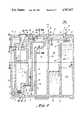
- FIG. 2is a vertical sectional view of the drainage device of this invention taken generally along the line II--II of FIG. 3.
- FIG. 3is a cross-sectional view of the device of this invention, taken generally along the line of III--III of FIGS. 1 and 2.
- FIG. 4is a fragmentary sectional view of the upper left hand portion of the device illustrated in FIGS. 1 and 2, being taken generally along the line IV--IV of FIGS. 1 and 2.
- FIG. 5is an enlarged fragmentary sectional view of a pressure release valve shown by the designated detail V of FIG. 4, and wherein the valve is shown in full line and phantom illustration, indicating respectively, closed and opened dispositions thereof.
- FIG. 6is a fragmentary transverse view of a portion of the upper left part of the device illustrated in FIGS. 1 and 2, being taken generally along the line VI--VI of FIGS. 1 and 2.
- FIG. 7is an enlarged fragmentary elevational view of the atmosphere inlet for the device of this invention, being taken generally along the line VII--VII of FIG. 6.
- FIG. 8is an enlarged fragmentary vertical sectional view taken generally along the line VIII--VIII of FIGS. 1 and 2 of the device.
- FIG. 9is an enlarged vertical transverse sectional view, taken generally along the line of IX--IX of FIG. 2.
- FIG. 10is an enlarged sectional view, taken through the extraction valve illustrated at the lower end of FIG. 9, generally along the line of X--X of FIG. 9.
- FIG. 11is an enlarged fragmentary transverse sectional view taken through the stand and lower end of the device, generally along the line of XI--XI of FIG. 1.
- FIG. 12is a sectional view taken through the device and stand, generally along the line of XII--XII of FIG. 11.
- FIG. 13is a fragmentary elevational view of the right end of the device illustrated in FIG. 1, with a removable patient record tape shown thereon.
- FIG. 14is a vertical sectional view through a modified form of the device of this invention to that illustrated in FIG. 2, wherein double cavity drainage is provided.
- FIG. 15is a fragmentary vertical sectional view through the lower end of a modified form of the device of this invention, wherein the device is provided with a connection for auto-transfusion.
- FIG. 16is a fragmentary vertical sectional view of another modified form of the device of this invention, wherein a transverse shelf is illustrated in the water seal, for enhancing visual observation of bubbles passing through the seal.
- FIG. 17is a fragmentary vertical sectional view of the upper portion of a modified device of this invention to that illustrated in FIG. 9, but wherein a baffle is provided as an alternative fluid control for preventing liquid flow while permitting air flow.
- FIG. 18is a fragmentary vertical sectional view, similar to that illustrated at the right end of FIG. 2, but wherein an additional chamber section is illustrated at the right end of the device.
- FIG. 19is an illustration of another alternative visual indicator for observation of an air leak, in the form of a bubble flowmeter.
- FIG. 20is a schematic representation of an embodiment of the apparatus of this invention in the format of a three bottle system.
- FIG. 1wherein the drainage device or apparatus, preferably for use as a chest drainage unit, such as for drainage of the pleural cavity, generally designated by the numeral 20, is shown in vertical or upstanding disposition.
- the device 20has upper and lower ends 21 and 22 respectively, left and right ends 23 and 24 respectively, and front and back portions 25 and 26 respectively.
- the main components of the device 20may be constructed of various materials and formed in various ways, such as vacuum forming, injection molding or blow molding of a thermoformed plastic material or the like, in the embodiment shown the main components of the device 20 are shown to comprise front and back molded member 27 and 28, and an additional molded member 30 at the upper left corner of FIG. 1, such members being secured together along various flanges such as, but not limited to those 31, 32, 33, by means of suitable heat sealing, adhesive and/or solvent sealing techniques generally known in the art.
- the device 20is provided with a suitable hose connection as at 35, of an inlet hose from the cavity of a patient, for delivering fluids, especially liquids, possibly with a certain amount of entrained solids therein, into a collection chamber 36 of the device through an inlet opening 37.
- Suction to the device 20is provided by means of a vacuum line 38, which will generally be of customary hospital supply, adjusted to 90-110 mm. Hg. of pressure, or any other suitable pressure, through vacuum opening 40.
- An opening to atmosphere 41is provided, for drawing ambient air from the atmosphere into the device, as needed.
- a water seal chamber 42is provided at the lower end of the device, between generally vertically disposed conduits 43 and 44.
- the water level in the seal chamber 42will generally be at the level shown by the dotted line 45 in FIG. 2, which should correspond with the level of the "0" designation shown in FIG. 1, to allow about 2 cm.
- conduit zone 50through fluid control member 51 (to be described in detail hereinafter), into an interconnecting conduit 52 formed by the wall 53 of the smaller molded member 30 sealingly disposed against front wall member 25, as at flanges 29, 29', as described above, through fluid control sheet member 54, into air/gas withdrawal zone 55 and out through the vacuum opening 40.
- zone 60In passing from chamber 36 to conduit 44, air/gases pass into zone 60 which feeds to conduit 44, by first passing into zone 61 (see FIG. 8) via opening 58, and then passing through the fluid control filter membrane 62, thereby providing gas/air communication between the cavity 36 and the water seal cavity 42.
- the filter membrane 62is constructed as a gas permeable, liquid impermeable membrane, to keep evacuate from a body cavity that has been collected in chamber 36, which will be generally in liquid form, perhaps with some solid particles therein, from entering the conduit 44 to the water seal chamber 42, but will permit gases to pass, as aforesaid.
- the conduit 43has a closure 64 at its upper end, which closure may take the form of a stopper, if desired, but in the alternative, the upper end of conduit 43 is provided with a cap-receiving opening 65, for receipt of a plastic or similar snap cap thereover, in either case to prevent the passage of water from the chamber 42, outwardly of the device 20, upon upset of the device from its vertical upstanding disposition illustrated in FIG. 2.
- the fill inlet 67is generally funnel-shaped and is thus contoured, as at 66, to facilitate pouring a pre-prepared quantity of water thereinto, to form the water seal that is provided in chamber 42.
- the fillingmay be through a bacteria filter 49, in which case the water used can be non-sterile ordinary tap water.
- filling of the water seal chamber 42may be effected through a hole 59 in a vertical surface (FIG. 9) which hole 59 is thereafter sealed closed with a suitable tape 59' or cap (not shown).
- the chamber 42may be constructed such that when it is turned 90° onto its left side from the position illustrated in FIG. 9, a bubble of air is trapped in zone 42', limiting the amount of fill into hole 59 by an amount determined by the volume of the bubble 42', such that, when turned erect as in FIG. 9, the correct predetermined level appears in the water seal chamber.
- a similar air bubble trap and vertical wall fillmay also or alternatively be provided for the manometer chamber.
- the vacuum draw from inlet 40which draws through zone 55, and via interconnecting channel 52 from zone 50 as well, draws from zone 68 (see FIG. 4) in the manometer of the device 20 of this invention, which manometer essentially comprises a U-shaped structure comprising upstanding conduits 68 and 70 connected by a water chamber 71.
- zone 68which manometer essentially comprises a U-shaped structure comprising upstanding conduits 68 and 70 connected by a water chamber 71.
- the low pressure created in that zone relative to atmospheric pressure outside the atmosphere opening 41maintains a desired predetermined water level 72 in the manometer chamber 71, which can be visually determined relative to a predetermined desired water pressure, by reference to the numbered chart at the left end of the device illustrated in FIG. 1.
- a level 72 at least halfway up the chamber 71is desired.
- the level of water in the manometer chamber 71thus determines the amount of control for the suction provided by the vacuum source, to a predetermined number of inches of water pressure, such as 20 inches of water pressure, or
- gas permeable, liquid impermeable filters 51, 54prevent water from manometer chamber 71 from entering water seal chamber 42, and the converse.
- conduit 68has a funnel-like construction 76, and a cap-receiving opening 77, similar to that illustrated at the upper end of FIG. 9 for the funnel-shaped opening 67.
- conduit 68is provided with a closure cap 78, as illustrated, for sealingly closing the same against discharge of water therefrom in the event of upsetting, although the cap 78 could alternately be replaced with a stopper such as that 64, or other tape or closure as desired.
- a cap 78, a stopper 64, or any combination thereofis utilized, it will be noted that in either case, there is no substantial protrusion of either the fill inlets 67 and 77, or the closures 64, 78, above the plane defined by the upper end 21 of the rest of the device 20, for accommodating placement of the device 20 beneath a hospital bed, as well as for precluding unnecessary protrusions that could otherwise become engaged by hospital sheets or limbs of a patient or the like, thereby knocking the device over from an upstanding position.
- the air inlet 41open to atmosphere, is constructed for entry of air into the front wall 25 of the device, rather than through a top wall thereof, to prevent ready blockage of the same by means of a sheet or the like falling over the top 21 of the device. Additionally, air inlet through the opening 41 is provided in two planes or more, such as in a plane perpendicular to the direction of the arrow 81 illustrated in FIG. 6, as well as in the four planes that are perpendicular to the directions of the arrows 82 at the upper left corner of FIG. 1, such that air can additionally enter the slots 83 between the laterally extending protrusions 84 of the inlet 41.
- a plurality of holes 84'can be made in horizontal and vertical surfaces on the air inlet side of filter member 74 to allow air inlet in a plurality of planes.
- the manometeris provided with a bubble breaker 86 shown seated in a molded seat 87 at the lower left end thereof, disposed a predetermined distance "T" above the bottom of chamber 71 such that air bubbles entering the liquid in the manometer below the level "L” have a short distance to travel (approximately 1 cm. upwardly after passing around the lower end of manometer separation wall 89, such distance "T” being sufficient to enable the bubbles to attain enough velocity to break when they strike against the bubble breaker 86.
- the bubble breaker 86is preferably constructed of a reticulated foam material of a sufficiently fine porosity that large bubbles will not pass into the liquid zone thereabove.
- the graduations illustrated at the left end of FIG. 1 for the manometer and for the water seal tubeprovide certain desirable visible indications.
- the attendantcan watch that the desired suction strength is provided for drawing liquid from the cavity to be drained, with rather precise measurement. Additionally, the attendant can make adjustments if need be, by adding water through the water inlet opening 77, as may be desired, to maintain the desired pressure.
- the narrow column or conduit 44 that is thus graduatedgives the attendant an ability to see unusual excursions of air, in the form of bubbles, coming from chamber 36, through the water seal.
- the level of water in the column or conduit 44can also be observed. For example, a rise in the level of water due to a patient sucking back air from chamber 36, such as during a coughing spell, can give a visual indication for the attendant of a condition that needs attention.
- a mechanismis provided for extracting water or other liquids from different locations of the device 20.
- watercan be extracted from the manometer, as for example in the case of an overfilling of the same, by withdrawing it from an access opening or port 90 of the type that is normally closed, but which may be open upon insertion of an appropriate tool, such as a needle-less syringe.
- watercan be added to or extracted from the water seal chamber 42 via access opening or port 91, similarly constructed. It will be noted that the water level 45 for chamber 42 is generally slightly above the location of the port 91, whereby extraction is facilitated during actual conditions of use of the device 20.
- a trough 92is provided just below the inlet 37 for liquid material, with the trough terminating rightward in a dam 99 for accumulating a small amount of just-removed liquid from the cavity therein. As additional liquid is accumulated, liquid overflows the dam, into an adjacent section of the chamber 36 therebelow.
- another extraction port 93is provided, in this case, in the vicinity of the trough 92, again for withdrawal of liquid, in this case liquid (with perhaps entrained solid particles therein) most recently drawn into the device from the body cavity.
- the access meansin the form of a valve, for removing liquid from the water seal at the location of port 91, it being understood that similar valve arrangements are preferably provided for the locations of liquid access ports 90 and 93, as well.
- the access port 91is provided with a commercially available valve 94, of suitable plastic construction or the like, normally solvent bonded to the wall 25 in which it is disposed.
- the valveis normally of two-piece construction, comprising an outer protruding tubular portion 95, and an inner protruding portion 96, with the portion 96 having a liquid access port 97 at its innermost end.
- a pressure-deformable member 98is disposed therein, such that, upon insertion of a needle-less syringe into opening 100, against outer end 101 of deformable member 98, will move the deformable member 98 back off its valve seat 102, whereby liquid entering opening 97 will be able to pass through openings (not shown) in wall portions 103, past valve seat 102, and out through opening 100, into the receiving cavity of a needle-less syringe, not shown.
- Access ports 90 and 91are located vertically in their chambers to provide a lower limit in each case for extracting liquid therethrough while the device is vertically disposed, to prevent withdrawing too much liquid during the extraction process.
- liquid impermeable sheet members 74, 51, 54 and 62such are preferably each of filter material, in generally vertical disposition as shown in the Figures, in the vertical or upstanding position of the device 20.
- filter membersare substantially hydrophobic, and in a preferred construction may have a polypropylene scrim fabric or polyester nonwoven fabric backing.
- a typical such filterwill be porous insofar as air or other gases are concerned, but is water or liquid-impermeable, at the pressures that will be encountered in the present device.
- the openings in the filtersmay for example be about 5 microns in the case of filters 51, 54 and 62, and 1 micron in the case of filter 74.
- the filter materialis commercially available.
- a positive pressure blowout valve 105on the back wall 26 of the device, whereby air pressure in the chamber 36 may travel, as aforesaid, via chamber 61, to chamber 60 down through conduit 44, through water chamber 42 and the seal provided therein, up through conduit 43, into zone 50 as seen in FIG. 4, and out through high pressure discharge openings 106, in the direction of arrows 107 shown in FIG. 5.
- the valve 105is carried on outer wall 26, by means of a central protrusion 108 extending through a hole in wall 26, with enlarged head 110 gripping the interior of the wall 26, such that the umbrella-like portion 111 thereof will move outwardly under pressure, away from covering the holes 106, from the full line position thereof illustrated in FIG. 4, to the phantom line position thereof illustrated in FIG. 5, whereby the air or other gases may escape as indicated by the arrows 112.
- the valve 105may be placed in a recess of outer wall 26, to prevent its accidental engagement and opening.
- the chamber 36 as illustrated in FIG. 2is provided with three chamber sections 115, 116, and 117. These chamber sections are free of communication except at the upper ends, over tops 118 and 119 of dividers 123 and 124 respectively.
- liquid from the collection chamber inlet opening 37has filled the trough 92, and is dripping downwardly over the dam 99 thereof into chamber section 115, in which it has filled, and liquid therefrom has spilled over the top 118 of divider or separator 123, and is now in the process of filling chamber section 116.
- the lower end 115a thereofis of lesser depth from front to back of the device than the upper end 115b of chamber section 115. This allows the initial material of liquid, with perhaps entrained solids, provided from the cavity being drained, to fill the chamber section 115a more rapidly in a vertical direction, for clearer observation by the medical attendant.
- the removable record member 120comprises a tape, generally with indicia that will correspond to measurements of volume, such as a unit measurement in cc.'s of liquid accumulated in cavity section 115.
- the member 120will generally be provided in the form of a tape having a release strip behind it, for removal of the strip, and adherence of the tape to the outer wall 25 of the device 20, as illustrated in FIG. 13, by means of an adhesive backing 121 provided on the tape.
- the exterior surface 122 of the tapewill normally be of a type that can accommodate writing thereon, such that the attendant, such as in the instance of a medical attendant to a patient, can write the patient's name on the tape, the time of each measurement, etc.
- This tapecan form a permanent record for the patient, such that it can be removed and then adhesively secured to the patient's medical chart.
- a tape with a perforated or other tear-off means for accomplishing the same purposemay be provided.
- other tapescan be provided on the front of other chamber sections 116 and 117, or even other chamber sections yet to be discussed hereinafter.
- a removal base 125is provided for the device 20.
- the base 125comprises an elongated rectangular plate 126, of substantially greater length "LL" than its width "W", as indicated in FIG. 12, such that, when it is disposed with its upstanding fingers 127 in mechanical engagement, with the exterior of a chamber section 117, either by friction fit gripping engagement as shown, or by locking therewith as by projection or male/female detent engagement (not shown), as desired, as at 128, it can hold the upstanding device, as illustrated in FIG. 1, securely supported against forward or backward falling, or tipping over.
- the upstanding projections 127form a socket 130 therebetween.
- the baseIn use, when the device 20 is to be retained in its upstanding disposition, the base is applied as illustrated in FIGS. 1, 11 and 12.
- the baseprior to use of the device 20, the base can be efficiently shipped with the unit, as a non-protrusive element in that it is packaged with the base rotated 90 degrees clockwise or counterclockwise as viewed in FIG. 12 relative to the chamber section 117, such that the outwardly extending legs of the base are retained below bottom 22 of the device, and are free of outward protrusions relative thereto, in front and rear directions.
- the basecan be similarly rotated for efficient storage beneath the chambers of the device.
- FIG. 14there is shown an alternative embodiment of the present invention 200, in which a pair of liquid inlets 201 and 202 are provided, for delivery of liquid from a pair of cavities simultaneously, into a corresponding pair of collection chambers 203, 204, respectively.
- the chambers 203 and 204are each provided with sampling troughs 205 and 206, and the chambers are separated from each other by a gas permeable, liquid impermeable sheet filter membrane 207, as described above, for permitting a single vacuum opening 208 to draw liquid from a pair of cavities.
- Each of the chambers 203, 204are provided with multiple sections as aforesaid.
- a single water sealed chamber 210is utilized, as is a single manometer chamber 211, all as described above with respect to the preferred embodiment.
- FIG. 15there is illustrated another alternative embodiment for the device 20 of this invention, in which facility is provided for auto-transfusion of blood that is removed from a body cavity in accordance with the several embodiments of this invention, in which the blood is delivered into a chamber section 301 of a collection chamber of a device 300.
- Other structures of the device 300may be pursuant to the embodiments otherwise described herein.
- an extraction valve 302is provided in an opening 303 preferably at a lower end of the collection device, with the valve 302 being generally constructed along the lines of that illustrated in FIG. 10.
- the valvein such a case is connected via feed line 304 to appropriate filter or other processing device 305, and to a blood pump 306, for re-injection into the patient.
- Such auto-transfusion apparatusis particularly desirable during operations in which it is not desired to use blood from another source than the patient's own body, in order to prevent disease from exterior contamination.
- FIG. 16there is illustrated another alternative embodiment of a device 400, in accordance with the present invention.
- the device 400is constructed preferably generally similar to the other embodiments described herein, except that at the lower end of the separation wall 402 between conduits 403 and 404 of the water seal chamber, there is provided a laterally extending shelf 405, the lower surface of which is tapered at "a", to preferably be within an angular range of 2-5 degrees.
- Thisprovides a mechanism whereby air bubbles traveling in the direction of arrow 406, down through conduit 403, through the chamber 401, may roll along the bottom surface of the shelf 405, as illustrated in FIG.
- FIG. 17there is illustrated another form of fluid control means for preventing undesired communication of liquid from one chamber to another, or outwardly of the apparatus, for example upon tipping of the device 500 onto a front face 501 or back face 502, if the device 500 is upset either leftwardly or rightwardly as viewed in FIG. 17, off its base (not shown).
- a baffle 503in the form of a slightly downwardly sloped frusto-conical protrusion, or funnel-like member 503, extending into a surrounding liquid reception zone 504, but stopping short of a wall 505 thereof.
- liquid from below the conduit 506may enter the reception zone 504, and enter the interior 507 of the baffle through its inlet 508.
- the capacity of the reception zone 504 and the lateral protrusion of the baffle 503 as viewed in FIG. 17will be constructed to have a predetermined size relative to the amount of liquid that will normally be contained below conduit 506, such that the amount of liquid that could fall onto the zone 504 will never be an amount sufficient to rise to the top of the tapered baffle 503 in its clockwise- fallen position.
- the device 500were to tip in a counterclockwise direction, on to its face 501 relative to its disposition in FIG. 17, liquid from below conduit 506 could not rise in liquid reception zone 504 sufficiently high to enter the opening 508 of the baffle 503.
- the devicefunctions as a fluid control means alternative to the gas permeable, liquid impermeable filter membrane discussed above.
- the illustration of FIG. 17is representative only, in order to avoid duplication hereof, and that the baffle 503 may, if desired, be substituted for each instance where such a filter membrane has been discussed hereinabove, although without the safe pressure management provided by the filters.
- FIG. 18there is illustrated another alternative embodiment of the device of this invention, generally designated by the numeral 600, which, while being fragmentally illustrated, is constructed similar to the other embodiments discussed herein, but wherein the liquid inlet opening 601 is adapted to receive liquid into a trough 602, and the trough has its dam 603 so located that liquid flow over the dam will fall into a very narrowly configured chamber section 604, to permit the greatest possible rise in height of a given amount of liquid for increased visual observation of color, particle accumulation, liquid separation, and numerous other factors that may be of interest to the attendant.
- a removable tapecalibrated with indicia, and capable of being written thereon, may be provided on the outside or casing of the device, for measuring and recording the observations within the chamber section 604. It will also be noted that the location of the dam 603 is in close relationship to and preferably slightly laterally extending to an amount less than the narrow width "N" of the chamber section 604 as indicated.
- an alternative device 700 to the shelf 405 of FIG. 16 for greater visual observation of an air leakis illustrated in the form of a bubble flowmeter 701, having an inlet 702 from the below-water level of the water seal chamber 703, and an outlet 704 to the vacuum draw outlet leg 705, with a vertical observation duct 706 therebetween, whereby a small amount of a detergent or other emulsifying agent is added to water in the seal chamber 703 and a preferably rubber squeeze bulb 707 is squeezed and allowed to expand, withdrawing soapy water into the bulb 707 and into duct 706.
- a bubble of air evidencing a leakenters duct 706 through inlet 702, it will form a readily observable meniscus 708, and travel up the duct 706 at an observable rate which may be recorded as volume versus measured time based on indicia or a scale (not shown) on the exterior of duct 706, thereby providing a valuable diagnostic tool.
- bubble meters per seare known to exist, their application to a drainage apparatus of the present type is believed to be novel.
- the present inventionis highly advantageous in that it provides a unit that can be safer, one that can be used after being upset, one which affords superior diagnostic capabilities, one which can be constructed to be sufficiently short in height to fit under a bed or the like to avoid opportunities for being upset, one which is easier to fill, and one which can be carried around by an ambulatory person.
- the devicecan be pre-filled if desired, and provided with a precise amount of water in the pertinent cavities thereof. In many instances, it will be preferable to provide the device with pre-packaged containers of water, premeasured in amount, with one container being provided for the water seal chamber and another, larger container being provided for the manometer. With the use of superior drainage equipment such as this, in medical situations, costs can be reduced by enabling patients to be removed from more complicated diagnostic equipment at an earlier time, enabling earlier discharge of the patient from the hospital.
Landscapes
- Health & Medical Sciences (AREA)
- Heart & Thoracic Surgery (AREA)
- Biomedical Technology (AREA)
- Vascular Medicine (AREA)
- Engineering & Computer Science (AREA)
- Anesthesiology (AREA)
- Pulmonology (AREA)
- Hematology (AREA)
- Life Sciences & Earth Sciences (AREA)
- Animal Behavior & Ethology (AREA)
- General Health & Medical Sciences (AREA)
- Public Health (AREA)
- Veterinary Medicine (AREA)
- External Artificial Organs (AREA)
Abstract
Description
Claims (35)
Priority Applications (6)
| Application Number | Priority Date | Filing Date | Title |
|---|---|---|---|
| US06/830,577US4767417A (en) | 1986-02-18 | 1986-02-18 | Drainage device for collecting liquids from a body cavity |
| US06/906,750US4781707A (en) | 1986-02-18 | 1986-09-12 | Process and apparatus for collecting blood from a body cavity for autotransfusion |
| US07/626,895US5133703A (en) | 1986-02-18 | 1990-12-13 | Process and apparatus for collecting blood of a patient for autotransfusion |
| US07/778,583US5203778A (en) | 1986-02-18 | 1991-10-17 | Process and apparatus for removal of insoluble fat from blood of a patient |
| US08/020,637US5354262A (en) | 1986-02-18 | 1993-02-22 | Apparatus for removal of insoluble fat from blood of a patient |
| US08/047,152US5372593A (en) | 1986-02-18 | 1993-04-13 | Process and apparatus for collecting blood of a patient for autotransfusion |
Applications Claiming Priority (1)
| Application Number | Priority Date | Filing Date | Title |
|---|---|---|---|
| US06/830,577US4767417A (en) | 1986-02-18 | 1986-02-18 | Drainage device for collecting liquids from a body cavity |
Related Child Applications (1)
| Application Number | Title | Priority Date | Filing Date |
|---|---|---|---|
| US06/906,750Continuation-In-PartUS4781707A (en) | 1986-02-18 | 1986-09-12 | Process and apparatus for collecting blood from a body cavity for autotransfusion |
Publications (1)
| Publication Number | Publication Date |
|---|---|
| US4767417Atrue US4767417A (en) | 1988-08-30 |
Family
ID=25257241
Family Applications (1)
| Application Number | Title | Priority Date | Filing Date |
|---|---|---|---|
| US06/830,577Expired - LifetimeUS4767417A (en) | 1986-02-18 | 1986-02-18 | Drainage device for collecting liquids from a body cavity |
Country Status (1)
| Country | Link |
|---|---|
| US (1) | US4767417A (en) |
Cited By (47)
| Publication number | Priority date | Publication date | Assignee | Title |
|---|---|---|---|---|
| US4892529A (en)* | 1986-10-24 | 1990-01-09 | Sherwood Medical Company | Method of autologous transfusion |
| US4925447A (en)* | 1988-06-22 | 1990-05-15 | Rosenblatt/Ima Invention Enterprises | Aspirator without partition wall for collection of bodily fluids including improved safety and efficiency elements |
| US4963135A (en)* | 1989-06-09 | 1990-10-16 | Sherwood Medical Company | Floatation chamber for use in a chest drainage device |
| US4981473A (en)* | 1988-06-22 | 1991-01-01 | Rosenblatt/Ima Invention Enterprises | Aspirator without partition wall for collection of bodily fluids including improved safety and efficiency elements |
| US4988342A (en)* | 1987-03-02 | 1991-01-29 | Atrium Medical Corporation | Improved fluid recovery system |
| US4994050A (en)* | 1989-10-31 | 1991-02-19 | Sherwood Medical Company | Float chamber and sleeve for use in a chest drainage device |
| US5002534A (en)* | 1988-06-22 | 1991-03-26 | Rosenblatt/Ima Invention Enterprises | Aspirator without partition wall for collection of bodily fluids including improved safety and efficiency elements |
| US5002529A (en)* | 1987-07-10 | 1991-03-26 | Solco Basle, Inc. | Postoperative wound drainage |
| WO1991017790A1 (en)* | 1990-05-11 | 1991-11-28 | Boehringer Laboratories | Method, apparatus for delivering or withdrawing fluid |
| US5074839A (en)* | 1989-08-24 | 1991-12-24 | Hemotrans, Inc. | Blood transfer apparatus |
| US5141504A (en)* | 1987-03-02 | 1992-08-25 | Atrium Medical Corporation | Fluid recovery system with stopcock suction control |
| US5279550A (en)* | 1991-12-19 | 1994-01-18 | Gish Biomedical, Inc. | Orthopedic autotransfusion system |
| US5372593A (en)* | 1986-02-18 | 1994-12-13 | Boehringer Laboratories | Process and apparatus for collecting blood of a patient for autotransfusion |
| US5645540A (en)* | 1994-10-11 | 1997-07-08 | Stryker Corporation | Blood conservation system |
| USD430286S (en)* | 1997-01-13 | 2000-08-29 | Genzyme Corporation | Drainage unit for draining bodily fluids from a patient |
| US6328709B1 (en)* | 1998-11-13 | 2001-12-11 | Pro Duct Health, Inc. | Devices and methods to identify ductal orifices during nipple aspiration |
| WO2002045778A3 (en)* | 2000-12-06 | 2002-10-31 | Sherwood Serv Ag | Fill spout for a drainage device |
| WO2002094347A1 (en)* | 2001-05-21 | 2002-11-28 | Sherwood Services Ag | Sampling port for a drainage device |
| US20040072503A1 (en)* | 2002-10-09 | 2004-04-15 | Taiwan Semiconductor Manufacturing Co., Ltd. | Dual mode hybrid control and method for CMP slurry |
| US20050234429A1 (en)* | 2004-04-17 | 2005-10-20 | Marco Geyer | Drainage chamber for collecting body fluids, in particular liquor |
| AU2002227340B2 (en)* | 2000-12-06 | 2007-02-01 | Cardinal Health 529, Llc | Vacuum setting and indication system for a drainage device |
| US20070189968A1 (en)* | 1999-06-11 | 2007-08-16 | Annette Bianchi | Gel composition for filling a breast milk duct prior to surgical excision of the duct or other breast tissue |
| US20100063463A1 (en)* | 2008-09-05 | 2010-03-11 | Tyco Healthcare Group Lp | Canister membrane for wound therapy system |
| US20100185165A1 (en)* | 2007-07-02 | 2010-07-22 | Max Middleton | Silencer for vacuum system of a wound drainage apparatus |
| US20100187065A1 (en)* | 2007-07-02 | 2010-07-29 | Andrew Pidgeon | Carrying Bag |
| US20100244780A1 (en)* | 2007-07-02 | 2010-09-30 | Jake Turner | Battery Recharging |
| EP2258417A1 (en)* | 2001-05-21 | 2010-12-08 | Covidien AG | Sampling port for a drainage device |
| US8882678B2 (en) | 2009-03-13 | 2014-11-11 | Atrium Medical Corporation | Pleural drainage system and method of use |
| US20160184498A1 (en)* | 2008-02-29 | 2016-06-30 | Kci Licensing, Inc. | System and method for collecting exudates |
| USD764047S1 (en) | 2014-05-28 | 2016-08-16 | Smith & Nephew, Inc. | Therapy unit assembly |
| USD764048S1 (en) | 2014-05-28 | 2016-08-16 | Smith & Nephew, Inc. | Device for applying negative pressure to a wound |
| USD764653S1 (en) | 2014-05-28 | 2016-08-23 | Smith & Nephew, Inc. | Canister for collecting wound exudate |
| USD764654S1 (en) | 2014-03-13 | 2016-08-23 | Smith & Nephew, Inc. | Canister for collecting wound exudate |
| USD765830S1 (en) | 2014-06-02 | 2016-09-06 | Smith & Nephew, Inc. | Therapy unit assembly |
| USD770173S1 (en) | 2014-06-02 | 2016-11-01 | Smith & Nephew, Inc. | Bag |
| WO2017070117A1 (en)* | 2015-10-19 | 2017-04-27 | Integrated Surgical LLC | Liquid-gas separator |
| US9956327B2 (en) | 2007-07-02 | 2018-05-01 | Smith & Nephew Plc | Wound treatment apparatus with exudate volume reduction by heat |
| US9974890B2 (en) | 2008-05-21 | 2018-05-22 | Smith & Nephew, Inc. | Wound therapy system and related methods therefor |
| US10071190B2 (en) | 2008-02-27 | 2018-09-11 | Smith & Nephew Plc | Fluid collection |
| US10130526B2 (en) | 2006-09-28 | 2018-11-20 | Smith & Nephew, Inc. | Portable wound therapy system |
| US10737000B2 (en) | 2008-08-21 | 2020-08-11 | Smith & Nephew, Inc. | Sensor with electrical contact protection for use in fluid collection canister and negative pressure wound therapy systems including same |
| US10744239B2 (en) | 2014-07-31 | 2020-08-18 | Smith & Nephew, Inc. | Leak detection in negative pressure wound therapy system |
| US10912869B2 (en) | 2008-05-21 | 2021-02-09 | Smith & Nephew, Inc. | Wound therapy system with related methods therefor |
| US11167072B2 (en)* | 2016-11-29 | 2021-11-09 | Murata Manufacturing Co., Ltd. | Suction discharge unit and suction discharge device |
| US11471571B2 (en) | 2017-04-19 | 2022-10-18 | Smith & Nephew, Inc. | Negative pressure wound therapy canisters |
| US12133789B2 (en) | 2014-07-31 | 2024-11-05 | Smith & Nephew, Inc. | Reduced pressure therapy apparatus construction and control |
| US12280203B2 (en) | 2019-10-03 | 2025-04-22 | T.J.Smith And Nephew, Limited | Apparatuses and methods for negative pressure wound therapy |
Citations (13)
| Publication number | Priority date | Publication date | Assignee | Title |
|---|---|---|---|---|
| US3363626A (en)* | 1966-03-17 | 1968-01-16 | J A Deknatel Inc | Underwater drainage apparatus |
| US3363627A (en)* | 1966-10-20 | 1968-01-16 | Deknatel Inc | Underwater drainage apparatus |
| US3517450A (en)* | 1968-02-23 | 1970-06-30 | Professional Tape Co Inc | Adhesived recording label |
| US3559647A (en)* | 1968-06-05 | 1971-02-02 | Deknatel Inc | Controllable underwater drainage apparatus |
| US3653913A (en)* | 1968-04-08 | 1972-04-04 | Adolf Rambold | Infusion bag |
| US3809085A (en)* | 1972-05-23 | 1974-05-07 | Deknatel Inc | Surgical drainage system |
| US3853128A (en)* | 1972-07-10 | 1974-12-10 | Deknated Inc | Valved underwater drainage apparatus |
| US4018224A (en)* | 1976-04-07 | 1977-04-19 | Deknatel, Inc. | Underwater drainage device with dual collection chambers |
| US4430085A (en)* | 1982-03-03 | 1984-02-07 | Ahrens Thomas S | Safety seal chest drainage unit with tipover seal control |
| US4439190A (en)* | 1981-04-27 | 1984-03-27 | Chesebrough-Pond's Inc. | Underwater drainage device |
| US4443220A (en)* | 1982-03-16 | 1984-04-17 | Hauer Jerome Maurice | Blood collection and transfer apparatus |
| US4455141A (en)* | 1982-06-08 | 1984-06-19 | Todd Edward P | Drainage apparatus with vacuum control |
| US4544370A (en)* | 1982-05-24 | 1985-10-01 | C. R. Bard, Inc. | Air leak detection system for chest fluid collection bottles and blow-out prevention baffle |
- 1986
- 1986-02-18USUS06/830,577patent/US4767417A/ennot_activeExpired - Lifetime
Patent Citations (13)
| Publication number | Priority date | Publication date | Assignee | Title |
|---|---|---|---|---|
| US3363626A (en)* | 1966-03-17 | 1968-01-16 | J A Deknatel Inc | Underwater drainage apparatus |
| US3363627A (en)* | 1966-10-20 | 1968-01-16 | Deknatel Inc | Underwater drainage apparatus |
| US3517450A (en)* | 1968-02-23 | 1970-06-30 | Professional Tape Co Inc | Adhesived recording label |
| US3653913A (en)* | 1968-04-08 | 1972-04-04 | Adolf Rambold | Infusion bag |
| US3559647A (en)* | 1968-06-05 | 1971-02-02 | Deknatel Inc | Controllable underwater drainage apparatus |
| US3809085A (en)* | 1972-05-23 | 1974-05-07 | Deknatel Inc | Surgical drainage system |
| US3853128A (en)* | 1972-07-10 | 1974-12-10 | Deknated Inc | Valved underwater drainage apparatus |
| US4018224A (en)* | 1976-04-07 | 1977-04-19 | Deknatel, Inc. | Underwater drainage device with dual collection chambers |
| US4439190A (en)* | 1981-04-27 | 1984-03-27 | Chesebrough-Pond's Inc. | Underwater drainage device |
| US4430085A (en)* | 1982-03-03 | 1984-02-07 | Ahrens Thomas S | Safety seal chest drainage unit with tipover seal control |
| US4443220A (en)* | 1982-03-16 | 1984-04-17 | Hauer Jerome Maurice | Blood collection and transfer apparatus |
| US4544370A (en)* | 1982-05-24 | 1985-10-01 | C. R. Bard, Inc. | Air leak detection system for chest fluid collection bottles and blow-out prevention baffle |
| US4455141A (en)* | 1982-06-08 | 1984-06-19 | Todd Edward P | Drainage apparatus with vacuum control |
Non-Patent Citations (24)
| Title |
|---|
| "Ohio Thoracic Drainage System", Ohio Medical Products, Madison, Wisconsin, 53707, 1983. |
| "Pneumo-Drain", Catalog Cot, Atrium Medical Corp. Amherst, N.H, 03031, 1983. |
| "Roberts 420-AC Pesto-Seal", Halkey-Roberts Corp., Paramus, New Jersey, 3/1983. |
| "Thora-Drain III Catalog Cot", Chesebrough-Ponds, Inc., Greenwich, Connecticut, 06830, 1980. |
| Argyl, brochure for Chest Drainage Unit.* |
| Beckton Dickenston, brochure for Suction Collection Canister.* |
| Beckton-Dickenston, brochure for Suction Collection Canister. |
| Chapter 4/Drainage Apparatus; pp. 67 97, The Pleural Space.* |
| Chapter 4/Drainage Apparatus; pp. 67-97, The Pleural Space. |
| Chesebrough Pond s Inc., brochure for Thora Drain III, Chest Drainage System.* |
| Chesebrough-Pond's Inc., brochure for Thora-Drain III, Chest Drainage System. |
| Davol Inc., instructions for Chest Drainage Unit.* |
| Emerson, brochure for Disposable Thoracic Drainage Sets.* |
| Halkey Medical, advertisement for Luer Style Syringe Check Valve.* |
| Howmedica, Inc., instructions for Pleur Evac Chest Drainage Unit.* |
| Howmedica, Inc., instructions for Pleur-Evac Chest Drainage Unit. |
| Ohio Medical Products, brochure for Thoracic Drainage System.* |
| Ohio Thoracic Drainage System , Ohio Medical Products, Madison, Wisconsin, 53707, 1983.* |
| Pneumo Drain , Catalog Cot, Atrium Medical Corp. Amherst, N.H, 03031, 1983.* |
| Roberts 420 AC Pesto Seal , Halkey Roberts Corp., Paramus, New Jersey, 3/1983.* |
| Sorenson Research advertisement for Drainage Device in Medical Electronic Products Magazine.* |
| Thora Drain III Catalog Cot , Chesebrough Ponds, Inc., Greenwich, Connecticut, 06830, 1980.* |
| W. L. Gore and Associates Inc., brochure for Gore Tex Membrane Products.* |
| W. L. Gore and Associates Inc., brochure for Gore-Tex Membrane Products. |
Cited By (94)
| Publication number | Priority date | Publication date | Assignee | Title |
|---|---|---|---|---|
| US5372593A (en)* | 1986-02-18 | 1994-12-13 | Boehringer Laboratories | Process and apparatus for collecting blood of a patient for autotransfusion |
| US4892529A (en)* | 1986-10-24 | 1990-01-09 | Sherwood Medical Company | Method of autologous transfusion |
| US5154712A (en)* | 1987-03-02 | 1992-10-13 | Atrium Medical Corporation | Fluid recovery system |
| US5141504A (en)* | 1987-03-02 | 1992-08-25 | Atrium Medical Corporation | Fluid recovery system with stopcock suction control |
| US4988342A (en)* | 1987-03-02 | 1991-01-29 | Atrium Medical Corporation | Improved fluid recovery system |
| US5002529A (en)* | 1987-07-10 | 1991-03-26 | Solco Basle, Inc. | Postoperative wound drainage |
| US4925447A (en)* | 1988-06-22 | 1990-05-15 | Rosenblatt/Ima Invention Enterprises | Aspirator without partition wall for collection of bodily fluids including improved safety and efficiency elements |
| US5002534A (en)* | 1988-06-22 | 1991-03-26 | Rosenblatt/Ima Invention Enterprises | Aspirator without partition wall for collection of bodily fluids including improved safety and efficiency elements |
| US4981473A (en)* | 1988-06-22 | 1991-01-01 | Rosenblatt/Ima Invention Enterprises | Aspirator without partition wall for collection of bodily fluids including improved safety and efficiency elements |
| US4963135A (en)* | 1989-06-09 | 1990-10-16 | Sherwood Medical Company | Floatation chamber for use in a chest drainage device |
| US5074839A (en)* | 1989-08-24 | 1991-12-24 | Hemotrans, Inc. | Blood transfer apparatus |
| US4994050A (en)* | 1989-10-31 | 1991-02-19 | Sherwood Medical Company | Float chamber and sleeve for use in a chest drainage device |
| US5120305A (en)* | 1990-05-11 | 1992-06-09 | Boehringer Laboratories | Method and apparatus for delivering or withdrawing fluids |
| WO1991017790A1 (en)* | 1990-05-11 | 1991-11-28 | Boehringer Laboratories | Method, apparatus for delivering or withdrawing fluid |
| US5279550A (en)* | 1991-12-19 | 1994-01-18 | Gish Biomedical, Inc. | Orthopedic autotransfusion system |
| US5645540A (en)* | 1994-10-11 | 1997-07-08 | Stryker Corporation | Blood conservation system |
| US5830198A (en)* | 1994-10-11 | 1998-11-03 | Stryker Corporation | Blood conservation system |
| USD430286S (en)* | 1997-01-13 | 2000-08-29 | Genzyme Corporation | Drainage unit for draining bodily fluids from a patient |
| US6328709B1 (en)* | 1998-11-13 | 2001-12-11 | Pro Duct Health, Inc. | Devices and methods to identify ductal orifices during nipple aspiration |
| WO2000029044A3 (en)* | 1998-11-13 | 2002-01-03 | Pro Duct Health Inc | Devices and methods to identify ductal orifices during nipple aspiration |
| US20110200695A1 (en)* | 1999-06-11 | 2011-08-18 | Annette Bianchi | Gel composition for filling a breast milk duct prior to surgical excision of the duct or other breast tissue |
| US20070189968A1 (en)* | 1999-06-11 | 2007-08-16 | Annette Bianchi | Gel composition for filling a breast milk duct prior to surgical excision of the duct or other breast tissue |
| AU2002228908B2 (en)* | 2000-12-06 | 2006-02-02 | Cardinal Health 529, Llc | Fill spout for a drainage device |
| WO2002045778A3 (en)* | 2000-12-06 | 2002-10-31 | Sherwood Serv Ag | Fill spout for a drainage device |
| AU2002227340B2 (en)* | 2000-12-06 | 2007-02-01 | Cardinal Health 529, Llc | Vacuum setting and indication system for a drainage device |
| US6659987B2 (en) | 2000-12-06 | 2003-12-09 | Sherwood Services Ag | Fill spout for a drainage device |
| KR100838508B1 (en)* | 2000-12-06 | 2008-06-17 | 코비디엔 아게 | Filling port for drainage device |
| EP2258417A1 (en)* | 2001-05-21 | 2010-12-08 | Covidien AG | Sampling port for a drainage device |
| US6632203B2 (en) | 2001-05-21 | 2003-10-14 | Sherwood Services Ag | Sampling port for a drainage device |
| WO2002094347A1 (en)* | 2001-05-21 | 2002-11-28 | Sherwood Services Ag | Sampling port for a drainage device |
| US20040072503A1 (en)* | 2002-10-09 | 2004-04-15 | Taiwan Semiconductor Manufacturing Co., Ltd. | Dual mode hybrid control and method for CMP slurry |
| US6926584B2 (en)* | 2002-10-09 | 2005-08-09 | Taiwan Semiconductor Manufacturing Co., Ltd. | Dual mode hybrid control and method for CMP slurry |
| US7214216B2 (en)* | 2004-04-17 | 2007-05-08 | Marco Geyer | Drainage chamber for collecting body fluids, in particular liquor |
| US20050234429A1 (en)* | 2004-04-17 | 2005-10-20 | Marco Geyer | Drainage chamber for collecting body fluids, in particular liquor |
| US11141325B2 (en) | 2006-09-28 | 2021-10-12 | Smith & Nephew, Inc. | Portable wound therapy system |
| US12115302B2 (en) | 2006-09-28 | 2024-10-15 | Smith & Nephew, Inc. | Portable wound therapy system |
| US10130526B2 (en) | 2006-09-28 | 2018-11-20 | Smith & Nephew, Inc. | Portable wound therapy system |
| US10188479B2 (en) | 2007-07-02 | 2019-01-29 | Smith & Nephew Plc | Carrying bag |
| US9642951B2 (en) | 2007-07-02 | 2017-05-09 | Smith & Nephew Plc | Silencer for vacuum system of a wound drainage apparatus |
| US8240470B2 (en) | 2007-07-02 | 2012-08-14 | Smith & Nephew Plc | Carrying bag |
| US8413812B2 (en) | 2007-07-02 | 2013-04-09 | Smith & Nephew Plc | Carrying bag |
| US8845603B2 (en) | 2007-07-02 | 2014-09-30 | Smith & Nephew Plc | Silencer for vacuum system of a wound drainage apparatus |
| US20100244780A1 (en)* | 2007-07-02 | 2010-09-30 | Jake Turner | Battery Recharging |
| US20100187065A1 (en)* | 2007-07-02 | 2010-07-29 | Andrew Pidgeon | Carrying Bag |
| US9192699B2 (en) | 2007-07-02 | 2015-11-24 | Smith & Nephew Plc | Silencer for vacuum system of a wound drainage apparatus |
| US9956327B2 (en) | 2007-07-02 | 2018-05-01 | Smith & Nephew Plc | Wound treatment apparatus with exudate volume reduction by heat |
| US10617800B2 (en) | 2007-07-02 | 2020-04-14 | Smith & Nephew Plc | Silencer for vacuum system of a wound drainage apparatus |
| US9572409B2 (en) | 2007-07-02 | 2017-02-21 | Smith & Nephew Plc | Carrying bag |
| US20100185165A1 (en)* | 2007-07-02 | 2010-07-22 | Max Middleton | Silencer for vacuum system of a wound drainage apparatus |
| US12201764B2 (en) | 2008-02-27 | 2025-01-21 | Smith & Nephew Plc | Fluid collection |
| US11141520B2 (en) | 2008-02-27 | 2021-10-12 | Smith & Nephew Plc | Fluid collection |
| US10071190B2 (en) | 2008-02-27 | 2018-09-11 | Smith & Nephew Plc | Fluid collection |
| US20200147278A1 (en)* | 2008-02-29 | 2020-05-14 | Kci Licensing, Inc. | System and method for collecting exudates |
| US20160184498A1 (en)* | 2008-02-29 | 2016-06-30 | Kci Licensing, Inc. | System and method for collecting exudates |
| US10518006B2 (en)* | 2008-02-29 | 2019-12-31 | Kci Licensing, Inc. | System and method for collecting exudates |
| US9974890B2 (en) | 2008-05-21 | 2018-05-22 | Smith & Nephew, Inc. | Wound therapy system and related methods therefor |
| US10912869B2 (en) | 2008-05-21 | 2021-02-09 | Smith & Nephew, Inc. | Wound therapy system with related methods therefor |
| US10967106B2 (en) | 2008-05-21 | 2021-04-06 | Smith & Nephew, Inc. | Wound therapy system and related methods therefor |
| US10737000B2 (en) | 2008-08-21 | 2020-08-11 | Smith & Nephew, Inc. | Sensor with electrical contact protection for use in fluid collection canister and negative pressure wound therapy systems including same |
| US20100063463A1 (en)* | 2008-09-05 | 2010-03-11 | Tyco Healthcare Group Lp | Canister membrane for wound therapy system |
| US9205235B2 (en) | 2008-09-05 | 2015-12-08 | Smith & Nephew, Inc. | Canister for wound therapy and related methods therefor |
| US10004835B2 (en) | 2008-09-05 | 2018-06-26 | Smith & Nephew, Inc. | Canister membrane for wound therapy system |
| US8177763B2 (en)* | 2008-09-05 | 2012-05-15 | Tyco Healthcare Group Lp | Canister membrane for wound therapy system |
| US10933175B2 (en) | 2009-03-13 | 2021-03-02 | Atrium Medical Corporation | Chest drainage systems and methods |
| US9814807B2 (en) | 2009-03-13 | 2017-11-14 | Atrium Medical Corporation | Chest drainage systems and methods |
| US9314599B2 (en) | 2009-03-13 | 2016-04-19 | Atrium Medical Corporation | Pleural drainage system and method of use |
| US8882678B2 (en) | 2009-03-13 | 2014-11-11 | Atrium Medical Corporation | Pleural drainage system and method of use |
| US8992493B2 (en) | 2009-03-13 | 2015-03-31 | Atrium Medical Corporation | Chest drainage systems and methods |
| US11896755B2 (en) | 2009-03-13 | 2024-02-13 | Atrium Medical Corporation | Chest drainage systems and methods |
| USD764654S1 (en) | 2014-03-13 | 2016-08-23 | Smith & Nephew, Inc. | Canister for collecting wound exudate |
| USD802744S1 (en) | 2014-03-13 | 2017-11-14 | Smith & Nephew Inc. | Canister for collecting wound exudate |
| USD813374S1 (en) | 2014-05-28 | 2018-03-20 | Smith & Nephew, Inc. | Canister for collecting wound exudate |
| USD815726S1 (en) | 2014-05-28 | 2018-04-17 | Smith & Nephew, Inc. | Therapy unit assembly |
| USD815727S1 (en) | 2014-05-28 | 2018-04-17 | Smith & Nephew, Inc. | Device for applying negative pressure to a wound |
| USD870265S1 (en) | 2014-05-28 | 2019-12-17 | Smith & Nephew, Inc. | Canister for collecting wound exudate |
| USD764047S1 (en) | 2014-05-28 | 2016-08-16 | Smith & Nephew, Inc. | Therapy unit assembly |
| USD764048S1 (en) | 2014-05-28 | 2016-08-16 | Smith & Nephew, Inc. | Device for applying negative pressure to a wound |
| USD891607S1 (en) | 2014-05-28 | 2020-07-28 | Smith & Nephew, Inc. | Device for applying negative pressure to a wound |
| USD764653S1 (en) | 2014-05-28 | 2016-08-23 | Smith & Nephew, Inc. | Canister for collecting wound exudate |
| USD853716S1 (en) | 2014-06-02 | 2019-07-16 | Smith & Nephew, Inc. | Bag |
| USD765830S1 (en) | 2014-06-02 | 2016-09-06 | Smith & Nephew, Inc. | Therapy unit assembly |
| USD770173S1 (en) | 2014-06-02 | 2016-11-01 | Smith & Nephew, Inc. | Bag |
| USD814016S1 (en) | 2014-06-02 | 2018-03-27 | Smith & Nephew Inc. | Therapy unit assembly |
| US12115298B2 (en) | 2014-07-31 | 2024-10-15 | Smith & Nephew, Inc. | Wound pressure determination for reduced pressure wound therapy |
| US10744239B2 (en) | 2014-07-31 | 2020-08-18 | Smith & Nephew, Inc. | Leak detection in negative pressure wound therapy system |
| US12133789B2 (en) | 2014-07-31 | 2024-11-05 | Smith & Nephew, Inc. | Reduced pressure therapy apparatus construction and control |
| KR102251497B1 (en) | 2015-10-19 | 2021-05-14 | 콘메드 코포레이션 | Liquefied-gas flow separator |
| AU2016341855B2 (en)* | 2015-10-19 | 2018-12-20 | Conmed Corporation | Liquid-gas separator |
| US10420867B2 (en) | 2015-10-19 | 2019-09-24 | Conmed Corporation | Liquid-gas Separator |
| WO2017070117A1 (en)* | 2015-10-19 | 2017-04-27 | Integrated Surgical LLC | Liquid-gas separator |
| KR20180072726A (en)* | 2015-10-19 | 2018-06-29 | 콘메드 코포레이션 | Liquefaction-gas separator |
| US11167072B2 (en)* | 2016-11-29 | 2021-11-09 | Murata Manufacturing Co., Ltd. | Suction discharge unit and suction discharge device |
| US11471571B2 (en) | 2017-04-19 | 2022-10-18 | Smith & Nephew, Inc. | Negative pressure wound therapy canisters |
| US12280203B2 (en) | 2019-10-03 | 2025-04-22 | T.J.Smith And Nephew, Limited | Apparatuses and methods for negative pressure wound therapy |
Similar Documents
| Publication | Publication Date | Title |
|---|---|---|
| US4767417A (en) | Drainage device for collecting liquids from a body cavity | |
| US5286262A (en) | Multipurpose collection vessel | |
| US4465485A (en) | Suction canister with unitary shut-off valve and filter features | |
| US4246909A (en) | Disposable urethral catheter assembly | |
| CA1046013A (en) | Thermoplastic bottle with controlled lateral collapse and method of dispensing liquid therefrom | |
| US5401262A (en) | Fluid recovery system | |
| US4976707A (en) | Fluid collection, storage and infusion apparatus | |
| US3478743A (en) | Closed urinary drainage system | |
| US4798578A (en) | Autotransfusion device | |
| US4265118A (en) | Urine collecting and measuring instrument | |
| US3685517A (en) | Aseptic disposable drainage receiver | |
| US4346711A (en) | Body fluid collection device with disposable liner | |
| US5397299A (en) | Fluid recovery system with improvements molded in body | |
| US3345980A (en) | Urometer | |
| CA1127042A (en) | Valve employing hydrophobic and hydrophilic membranes | |
| US4223695A (en) | Novel valve employing hydrophobic and hydrophilic membranes | |
| US4769019A (en) | Drainage apparatus | |
| US5011470A (en) | Combined surgical drainage and autotransfusion apparatus | |
| EP0615759B1 (en) | Drainage device for use with suction or gravity flow | |
| JPS6258263B2 (en) | ||
| US4312351A (en) | Drainage device with separate outflow chamber | |
| EP0081577A1 (en) | Pleural drainage system | |
| CA1170533A (en) | Thoracic drainage unit | |
| CN113855876A (en) | Thoracic drainage bottle | |
| US3820546A (en) | Combined air vent,filter and adapter for urinary drainage assemblies |
Legal Events
| Date | Code | Title | Description |
|---|---|---|---|
| AS | Assignment | Owner name:BOEHRINGER LABORATORIES, 427 PARKVIEW DRIVE, WYNNE Free format text:ASSIGNMENT OF ASSIGNORS INTEREST.;ASSIGNORS:BOEHRINGER, JOHN R.;KARPOWICZ, JOHN;SUTTER, STEVEN T.;REEL/FRAME:004549/0829 Effective date:19860311 Owner name:BOEHRINGER LABORATORIES, PENNSYLVANIA Free format text:ASSIGNMENT OF ASSIGNORS INTEREST;ASSIGNORS:BOEHRINGER, JOHN R.;KARPOWICZ, JOHN;SUTTER, STEVEN T.;REEL/FRAME:004549/0829 Effective date:19860311 | |
| STCF | Information on status: patent grant | Free format text:PATENTED CASE | |
| CC | Certificate of correction | ||
| FPAY | Fee payment | Year of fee payment:4 | |
| FPAY | Fee payment | Year of fee payment:8 | |
| FEPP | Fee payment procedure | Free format text:PAYOR NUMBER ASSIGNED (ORIGINAL EVENT CODE: ASPN); ENTITY STATUS OF PATENT OWNER: SMALL ENTITY | |
| FPAY | Fee payment | Year of fee payment:12 | |
| AS | Assignment | Owner name:FIRSTRUST BANK, PENNSYLVANIA Free format text:SECURITY AGREEMENT;ASSIGNOR:BOEHRINGER LABORATORIES, INC.;REEL/FRAME:019102/0068 Effective date:20070306 |