US4767404A - Surgical suction device having a perforated sleeve - Google Patents
Surgical suction device having a perforated sleeveDownload PDFInfo
- Publication number
- US4767404A US4767404AUS06/885,447US88544786AUS4767404AUS 4767404 AUS4767404 AUS 4767404AUS 88544786 AUS88544786 AUS 88544786AUS 4767404 AUS4767404 AUS 4767404A
- Authority
- US
- United States
- Prior art keywords
- suction
- suction port
- end section
- perforate
- surface portion
- Prior art date
- Legal status (The legal status is an assumption and is not a legal conclusion. Google has not performed a legal analysis and makes no representation as to the accuracy of the status listed.)
- Expired - Lifetime
Links
- 238000004891communicationMethods0.000claimsdescription4
- 208000014674injuryDiseases0.000abstractdescription7
- 230000008733traumaEffects0.000abstractdescription6
- 230000000903blocking effectEffects0.000abstractdescription3
- 210000001519tissueAnatomy0.000description22
- 238000001356surgical procedureMethods0.000description18
- 239000007787solidSubstances0.000description13
- 238000000034methodMethods0.000description12
- 210000000988bone and boneAnatomy0.000description11
- 230000000399orthopedic effectEffects0.000description11
- 239000012530fluidSubstances0.000description9
- 239000000463materialSubstances0.000description9
- 239000008280bloodSubstances0.000description8
- 210000004369bloodAnatomy0.000description8
- 239000002245particleSubstances0.000description8
- 239000003146anticoagulant agentSubstances0.000description7
- 229940127219anticoagulant drugDrugs0.000description7
- 238000009826distributionMethods0.000description4
- 230000006378damageEffects0.000description3
- 230000014759maintenance of locationEffects0.000description3
- 238000004519manufacturing processMethods0.000description3
- 238000010008shearingMethods0.000description3
- 206010053567CoagulopathiesDiseases0.000description2
- 230000035602clottingEffects0.000description2
- 238000010276constructionMethods0.000description2
- 230000002035prolonged effectEffects0.000description2
- 230000000717retained effectEffects0.000description2
- 239000012056semi-solid materialSubstances0.000description2
- 206010002091AnaesthesiaDiseases0.000description1
- FAPWRFPIFSIZLT-UHFFFAOYSA-MSodium chlorideChemical compound[Na+].[Cl-]FAPWRFPIFSIZLT-UHFFFAOYSA-M0.000description1
- 208000007536ThrombosisDiseases0.000description1
- 208000027418Wounds and injuryDiseases0.000description1
- 230000001154acute effectEffects0.000description1
- 230000037005anaesthesiaEffects0.000description1
- 239000011248coating agentSubstances0.000description1
- 238000000576coating methodMethods0.000description1
- 150000001875compoundsChemical class0.000description1
- 238000005520cutting processMethods0.000description1
- 229910003460diamondInorganic materials0.000description1
- 239000010432diamondSubstances0.000description1
- 238000006073displacement reactionMethods0.000description1
- 239000007788liquidSubstances0.000description1
- 239000002184metalSubstances0.000description1
- 239000000203mixtureSubstances0.000description1
- 238000012986modificationMethods0.000description1
- 230000004048modificationEffects0.000description1
- 230000001105regulatory effectEffects0.000description1
- 238000004513sizingMethods0.000description1
- 239000011780sodium chlorideSubstances0.000description1
- 229910001220stainless steelInorganic materials0.000description1
- 239000010935stainless steelSubstances0.000description1
- 210000003813thumbAnatomy0.000description1
- 210000000689upper legAnatomy0.000description1
Images


Classifications
- A—HUMAN NECESSITIES
- A61—MEDICAL OR VETERINARY SCIENCE; HYGIENE
- A61M—DEVICES FOR INTRODUCING MEDIA INTO, OR ONTO, THE BODY; DEVICES FOR TRANSDUCING BODY MEDIA OR FOR TAKING MEDIA FROM THE BODY; DEVICES FOR PRODUCING OR ENDING SLEEP OR STUPOR
- A61M1/00—Suction or pumping devices for medical purposes; Devices for carrying-off, for treatment of, or for carrying-over, body-liquids; Drainage systems
- A61M1/84—Drainage tubes; Aspiration tips
- Y—GENERAL TAGGING OF NEW TECHNOLOGICAL DEVELOPMENTS; GENERAL TAGGING OF CROSS-SECTIONAL TECHNOLOGIES SPANNING OVER SEVERAL SECTIONS OF THE IPC; TECHNICAL SUBJECTS COVERED BY FORMER USPC CROSS-REFERENCE ART COLLECTIONS [XRACs] AND DIGESTS
- Y10—TECHNICAL SUBJECTS COVERED BY FORMER USPC
- Y10S—TECHNICAL SUBJECTS COVERED BY FORMER USPC CROSS-REFERENCE ART COLLECTIONS [XRACs] AND DIGESTS
- Y10S604/00—Surgery
- Y10S604/902—Suction wands
Definitions
- This inventionrelates to surgical suction devices for the removal of surgical debris.
- Suction devicesare used during surgical procedures to remove fluids and debris from the operating field.
- Various designshave been proposed for these devices.
- such devicesinclude a tip which is inserted into the surgical field and a means, usually a conduit or a tube, for connecting the tip to a vacuum source.
- a meansusually a conduit or a tube, for connecting the tip to a vacuum source.
- these known deviceshave proven unsatisfactory in some aspect.
- the designer of a surgical suction devicemust consider various factors.
- the devicemust be easy and convenient to use and must minimize the amount of disruption to the surgeon.
- the time required to clear the fieldmay impact both the total length of the procedure and the ability of the surgeon to identify problems within the field and complete the procedure.
- the length of the procedureaffects both the surgeon and the patient. Procedures lengthened unnecessarily are unduly tiring to the surgeon and expose the patient to anesthesia for a prolonged period. Therefore, the time required to use the device must be minimized. Ease of use contributes to minimization of the time required to complete the surgery and facilitates operation of the device by less trained personnel.
- the devicemust also minimize the disruption of the patient's tissues. Aspects of disruption which must be considered include the size of the incision required and the trauma to tissue should it be aspirated into the device.
- the suction deviceshould not require that the operating field be adjusted to accommodate it. Further, it is inevitable that tissue will be exposed to suction through inadvertence or inability to properly clear the field without impinging upon tissue. Therefore, the device should minimize tissue trauma by minimizing both the space required to use it and the tendency to injure aspirated tissue.
- the suction devicemust clear the field effectively.
- blood and other fluidssuch as saline irrigating fluid and the like, will be present in the operating field.
- Solids and semi-solidssuch as coagulated blood, bone chips, excised tissue particles, and the like will also be present. All these materials must be removed from the operating field without extraordinary effort. The device must continue to operate effectively in the presence of these materials without requiring repeated and prolonged interruptions to unblock the device.
- the anti-coagulant delivery device described in U.S. Pat. No. 3,955,573is intended for use in autologous blood transfusion. Therein, anti-coagulant is delivered within a bulbous suction tip designed to thoroughly mix the anti-coagulant with the blood being aspirated. Therefore, the clotting tendency is almost immediately suppressed, thereby preventing clotting and blockages within the device.
- U.S. Pat. No. 2,804,075discloses an anti-coagulant delivery system and teaches that when the suction holes become blocked, anti-coagulant accumulates within the tip and usually clears the blocked holes.
- bone chipsare said not be able to block the aspirator because the holes in the suction tip are smaller than the suction tube diameter. However, this does not explain why a bone chip might not block the suction tip itself nor how a blockage which is not affected by anti-coagulant, such as a flat globule or a piece of excised tissue, would be removed.
- this inventionrelates to a suction device to be attached to a vacuum source for removal of surgical debris
- a suction deviceto be attached to a vacuum source for removal of surgical debris
- the elongated sectioncontains a perforate end section in communication with a hollow central suction conduit which forms a passageway for the aspirated debris.
- the perforate end sectionhas a perforate first surface portion extending from the end of the elongated section to the widest part of the perforate end section, and a perforate second surface portion extending from the widest part of the perforate end section to the distal end of the end section.
- Perforationsform suction ports for the aspiration of debris through suction port conduits which communicate between the suction ports and the hollow central suction conduit.
- a hollow handlewhich communicates between the vacuum source and the hollow conduit, defines a passageway for the aspirated debris.
- the inventionfurther relates to a suction device wherein the elongated section and part of the perforate end section are surrounded by a coaxially disposed perforate sleeve extending substantially from the end of the elongated section to the widest part of the perforate end section and having substantially the same size as the widest part of the end.
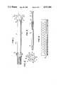
- FIG. 1illustrates a preferred embodiment of a suction device used in the present invention.
- FIG. 2is an end view of the suction device shown in FIG. 1.
- FIG. 3illustrates the assembly of the device together with a hollow handle according to the invention.
- FIG. 4shows a preferred embodiment of the perforate sleeve intended to surround the elongated section and part of the perforate end section according to the invention.
- FIG. 5is an exploded perspective view of the assembly containing the device, sleeve, and handle, of the present invention.
- FIG. 6illustrates a surgical suction device, including a sleeve, according to the invention.
- FIG. 7illustrates an alternative embodiment of a suction device.
- FIGS. 8 and 9illustrate the relationship of the intersection of suction port conduits with the hollow central suction conduit.
- a surgical suction devicecan be made convenient to use, clog resistant, efficient, and able to quickly clear an operating field of surgical debris while minimizing damage to tissue by disposing suction ports on a first surface portion of a perforate end section of the device so that these suction ports act as a vacuum modulator when suction ports on the second surface portion of the tip become clogged.
- suction ports on a first surface portion of a perforate end section of the deviceso that these suction ports act as a vacuum modulator when suction ports on the second surface portion of the tip become clogged.
- debris which becomes lodged in suction ports on the second surface portionis not subjected to the entire vacuum because other ports remain open.
- tissueis not traumatized by being strongly aspirated into the suction ports.
- Lodged debriscan often be dislodged simply by moving the device or rotating it within the operating field.
- the devicesimply can be removed from the field and wiped on another surface.
- the particleis easily removed from the suction ports because the vacuum is modulated by the non-plugged suction ports.
- the strength of the vacuumis automatically regulated without the need for a separate vacuum adjustment technique, such as the ability to expose additional suction ports in the tip. Further, debris which does become lodged in a suction port can be removed without the need for a shearing or cutting device.
- FIG. 1illustrates a preferred embodiment of device 10 comprising elongated section 11 containing hollow central suction conduit 14 and perforate end section 12 through which hollow central suction conduit 14 continues.
- perforate end section 12is bulbous. However, the perforate end of the tip need not be bulbous.
- Perforate end section 12can have any enclosed shape which provides a first surface portion 16 extending outwardly from the end 18 of elongated section 11. Hollow central section conduit 14 continues through perforate end section 12.
- First surface portion 16can be of any shape which is narrow at one end and widest at the other.
- An example of another suitable first surface portionis a frusto-conical section. Those skilled in the art are familar with other suitable first surface.
- First surface portion 16need not be oriented on the axis of hollow central suction conduit 14. Instead, first surface portion 16 could be oriented at an acute angle from the axis of hollow central suction conduit 14.
- FIG. 7is an illustration of a tip with such an orientation.
- hollow central suction conduit 14need not be straight. It may have any curve or compound curves desired.
- FIG. 2depicts an end view of perforate end section 12, clearly illustrating a planar face 15 and the relationship between suction ports 13 in the second surface portion of perforate end section 12 and suction port 20 in planar face 15 of the second surface portion.
- the embodiment illustrated thereinhas three suction ports 13, each of which is substantially the same size, symmetrically placed about second surface portion of the perforate end section 12, and one suction port 20 centered in planar face 15.
- the suction ports 13 in the second surface portion of perforate end section 12should be of the same size and these suction ports, together with suction port 20 in planar face 15, if the second surface portion has a planar face, should be symmetrically placed about the face and the second surface portion of the end, thus ensuring even distribution of suction.
- the size of the suction portsis not critical, certain criteria should be considered when sizing the suction ports.
- the suction ports on the second surface portion of the endshould be of the same size and symmetrically placed to ensure even distribution of the vacuum.
- the number of suction portsis theoretically unlimited.
- practical considerationsestablish limits on the suction port size and placement.
- two suction portscould be symmetrically arranged on the second surface portion of perforate end section 12, the operability of the device would be reduced. Therefore, the fewest preferred number of suction ports in the second surface portion of the perforate end section 12 is three.
- the suction portscommunicate with hollow central suction conduit 14 via suction port conduits.
- Each suction port conduitpreferably has the same cross-sectional size and shape as the suction port with which it communicates.
- the suction port conduitcan have any cross-sectional size and shape which is not smaller than the cross-sectional size and shape of the associated suction port. This limitation ensures that solid or semi-solid particles of debris aspirated through the suction port will thus also be aspirated through the suction port conduit.
- FIG. 8illustrates the relative length of suction port conduits 23, in communication with suction ports 17 in first surface portion 16, and suction port conduit 21, in communication with suction port 20, in a preferred embodiment of this invention.
- suction port conduit 21preferably is short, as illustrated in FIG. 8, it could be extended further into the interior of perforated end section 12.
- the maximum number of suction portsis limited by the ability to manufacture a device having sufficient structural strength and by the minimum desired suction port size.
- the latter criterionestablishes the practical limitation for the purposes of this invention, as the suction ports must be large enough to aspirate at least some of the non-fluid debris.
- This debrissuch as fat globules, excised tissue, clotted blood, bone chips, and the like, can be removed either by aspirating the debris or by allowing the debris to become trapped in a suction port and then removing the suction device from the field to physically remove the entrapped debris. Therefore, those skilled in the art will be able to select the size for the suction ports disposed about the perforate end portion of the device and a symmetrical arrangement of these suction ports suitable for the purpose intended.
- the suction device of this inventionis particularly useful in orthopedic surgery. During such surgery, suction devices are required to remove dense viscous fluids, irrigating fluid, particles of bone and plastic, and similar debris.
- the preferred diameter of each of the three suction ports 13 in the second surface portion of the perforate end section 12is between about 0.09 to 0.15 inch, more preferably between about 0.10 to 0.13 inch.
- the preferred diameter of suction port 20 in planar face 15is between about 0.15 to 0.20 inch, more preferably between about 0.16 to 0.18 inch.
- Such dimensionsare advantageously utilized to aspirate the above-described debris. However, these guidelines should in no way be considered limiting because, as is clear to those in the art, other dimensions could be utilized advantageously in other applications.
- FIG. 1further illustrates placement of suction ports 17 in first surface portion 16 of perforate end section 12.
- the suction portsare preferably symmetrically arranged on first surface portion 16 and preferably are of equal size to ensure symmetrical distribution of the vacuum force. Because suction ports 17 on first surface portion 16 are not located on the same surface as are suction ports 13 and 20, they typically remain useful even if suction ports 13 and 20 become blocked for any reason.
- the device 10can be advantageously utilized to aspirate pools of fluids containing solid and semi-solid debris which tends to block suction ports 13 and 20.
- Suction ports 17also function as an automatic vacuum modulator, facilitating operation of the tip under conditions conducive to blockage. Debris which becomes lodged in suction ports 13 and 20 is not subjected to the entire vacuum force because suction ports 17 remain open. Therefore, a large particle can be removed from the suction port with a simple wipe on a surgical towel, sponge, or other suitable area. The vacuum need not be temporarily interrupted to remove the blockage. Further, suction ports 17 continue to function while suction ports 13 and 20 are blocked, thus continuing to remove fluid and debris from the field.
- the vacuum modulation feature of the tip of this inventionalso reduces trauma to aspirated tissue. Tissue aspirated into suction ports 13 and 20 does not typically receive the entire force of the vacuum because suction ports 17 will typically remain open. Therefore, injury to aspirated tissue is reduced.
- a preferred embodimentis to utilize three suction ports 17, each having a diameter of between about 0.06 to 0.11 inch, preferably between about 0.08 to 0.10 inch.
- the dimensionsare advantageously used to aspirate debris from orthopedic surgery, but in no way should they be considered limiting. Those skilled in the art will be able to adapt the structure for use in surgery and applications wherein different suction port dimensions and arrangements will be effective.
- Vacuum modulationis affected by the ratio of the cross-sectional area of the suction ports 13 and 20 on the second surface portion of perforate end section 12 to the cross-sectional area of the suction ports 17 on first surface portion 16. Therefore, those skilled in the art will be able to adjust this ratio to satisfy particular needs. For orthopedic surgery, a ratio between about 1.3 to 10 is suitable, with a ratio between about 1.9 to 4.3 preferable.
- this suction deviceis enhanced by its superior ability to aspirate bone chips and other solid or semi-solid debris such as fat globules, blood clots, excised tissue particles, and the like. If such material becomes lodged in a suction port, it can be removed by removing the device from the surgical field and wiping the tip.
- this inventionis especially suitable for removal of semi-solids without disrupting the surgical procedure. First, it is sometimes possible to remove semi-solid blocking material merely by moving the device within the field to cause the semi-solid material to contact a plurality of suction ports. The additional force which will then be brought to bear on this semi-solid material is often sufficient to break the blockage into a plurality of pieces small enough to be aspirated.
- the suction port conduitscan be arranged within the perforate end section to create turbulence at the intersections of the suction port conduits and the hollow central suction conduit within the device. This turbulence impinges upon that fraction of the blockage which is within the suction port conduit or which is caught on the intersection of the suction port conduits and hollow central suction conduit, and typically dislodges the blockage.
- FIG. 8illustrates the preferred orientation of suction port conduits 11, which are associated with suction ports 17 in first surface portion 16.
- the relative location of the intersection of one suction port conduit 22 with hollow central suction conduit 14is also illustrated.
- FIG. 9illustrates the preferred orieintation of suction port conduits 22, which are associated with suction ports 13 in the section surface portion of perforate end portion 12.
- the relative location of the intersection of one suction conduit 23 with hollow central suction conduit 14is also shown.
- Each figurealso illustrates the location of suction port 20 and suction port conduit 21.
- suction port conduits 23 and 22could be disposed perpendicular to hollow central suction conduit 14, the preferred arrangements are illustrated in FIGS. 8 and 9.
- hollow central suction conduit 14 and suction port conduits 23intersect at approximately equal distances from the distal end of perforate end section 12, and suction port conduits 23 are disposed generally in the direction of the distal end of perforate end section 12.
- suction port conduits 22preferably intersect hollow central suction conduit 14 at approximately equal distance from the distal end of perforate end section 12, and suction port conduits 22 are disposed generally away from the distal end of perforate end section 12.
- the intersections of hollow central suction conduit 14 with suction port conduits 22are preferably closer to the distal end of perforate end portion 12 than are the intersections of hollow central suction conduit 14 with suction port conduits 23.
- FIG. 8further illustrates that hollow central suction conduit 14 preferably has a diameter larger than any of the suction ports and suction port conduits so that aspirated material does not become lodged within the device. To dislodge such a blockage would require taking the device out of service and manually removing the blockage.
- hollow central suction conduit 14has an interior diameter of approximately 0.18 to 0.23 inches, and is preferably larger than the largest suction port or suction port conduit. Those skilled in the art can change this diameter to one more suitable for their intended use.
- FIG. 3illustrates the use of the device in conjunction with hollow handle 30.
- handle 30is hollow so as to form a passageway for aspirated debris from hollow central suction conduit 14 to the vacuum source and is adapted at one end 31 to be removably connected to hollow central suction conduit 14, and at the other end 32 to be attached to a vacuum source.
- the particular method of removably attaching these parts to each otheris not critical to the invention.
- a typical friction-type hose connectionis illustrated at end 32 where hollow handle 30 is attached to the vacuum source, any vacuum-tight connection technique known to those skilled in the art could be utilized.
- illustrated threaded connection 31could be a slip-joint (lug and slot), a snap-joint, or any other vacuum-tight connection technique.
- a positive retention techniqueis preferred so that the device does not become dislodged or disconnected from the handle during surgery.
- a threaded jointis preferred.
- the inside diameter of hollow handle 30should be no less than the inside diameter of hollow central suction conduit 14. Further, although no special design need be placed on the surface of handle 30, if desired, an anti-slip surface such as the diamond pattern illustrated in part in FIG. 6 can be employed. Further, suitable coating material can be utilized.
- the outside diameter of the hollow handle 40is preferably the same as that of the sleeve and is adapted to abut sleeve 40.
- Device 10is also adapted to receive perforated sleeve 40, illustrated in FIG. 4.
- the particular method of attachment of sleeve 40 to device 10is not critical for this invention.
- FIG. 5illustrates the relationship between a substantial portion 40' of sleeve 40 and device 10
- FIG. 6depicts an entire assembly including device 10 (of which only the second surface portion of perforate end section 12 is visible), sleeve 40, and handle 30.
- no positive attachment deviceneed be utilized, such a device is preferred.
- Great strainis placed on the sleeve when, for example, the device is utilized to suction a long bone in orthopedic surgery.
- shoulder 19 or perforated end section 12could be threaded and the appropriate end of sleeve 40 oppositely threaded.
- a retaining pin or lugcould be placed on shoulder 19 or perforated end section 12 and a slot appropriately placed on sleeve 40 and shaped so that the pin is received in the slot to retain sleeve 40.
- the lug or pin portion of the retention devicecould be attached to the exterior of elongated section 11.
- other positive retention devicescan be utilized.
- the outside dimension of handle end 31 and the widest dimension of perforate end section 12are substantially equal, and the largest dimension of shoulder 19 is slightly smaller than the handle.
- the inside dimension of sleeve 40can advantageously be selected so that sleeve 40 can be put in place by removing device 10 from handle 30, sliding sleeve 40 over shoulder 19 of device 10 so that one end abuts against the widest dimension of perforate end section 12, and, upon replacement of device 10 on handle 30, the other end of the sleeve abuts handle end 31.
- the sleevemust not block suction ports 17. It is also preferred that the outside dimension of sleeve 40 equal to the widest dimension of perforate end section 12.
- ends of the walls of sleeve 40are preferably shaped to match the shape of those portions of handle end 31 and perforate end section 12 against which sleeve 40 abuts. Matching shapes in this fashion helps ensure not only that sleeve 40 is properly centered and retained on device 10, but also that vacuum is directed to sleeve 40 and not to the joint between sleeve 40 and perforate end section 12.
- Sleeve 40can be urged over the largest dimension of perforate end section 12 and held against knob or shoulder 19 of device. Appropriate selection of the dimensions of sleeve 40, shoulder 19, and perforate end section 12 allows sleeve 40 to be retained on device 10 by force or friction. However, this embodiment is not preferred when stress placed on the sleeve might cause the sleeve to be dislodged.
- Perforations in sleeve 40should be smaller than suction ports 17 to avoid blocking suction ports 17 while the sleeve is in place. Any solid which is aspirated through the sleeve perforations will thus also be aspirated through the larger suction ports 17. Further, the distance between the interior of sleeve 40 and the exterior of elongated section 11 should be least as large as the perforations in sleeve 40 so that aspirated material does not lodge between the sleeve and the elongated section. The diameter and arrangement of the perforations can be selected by one skilled in the art.
- Sleeve 40is intended for use in situations where the volume of liquids to be aspirated is large, or when the device must be inserted into a deep field. Therefore, use of sleeve 40 is preferred during orthopedic surgery, because large volumes of irrigating fluid are typically used to clear the operating field of blood, bone chips, and the like. Further, the device must often be inserted deep into or along side of a bone such as the femur.
- the perforations in the sleevepreferably have a diameter between about 0.05 to 0.10 inch, preferably between about 0.07 to 0.09 inch, but preferably smaller than that of suction ports 17.
- Sleeve 40is also useful in reducing trauma to tissue. In situations where it is necessary to insert device 10 deep into an area surrounded by tissue, or deep into a long bone, as in orthopedic surgery, sleeve 40 can be advantageously by used to ensure that tissue or solid and semi-solid debris do not block suction ports 17.
- the superior performance of the device of this inventioncan be utilized advantageously by reducing the size of the device.
- the widest dimension of the preferred bulbous perforate end section 12 for use in orthopedic surgery as described aboveis between about 0.30 to 0.50 inch, preferably between about 0.32 to 0.44 inch.
- the length of elongated section 11can be selected to meet the user's needs. For orthopedic surgery, lengths of between about 2 to 3 inches are preferred.
- any of the appropriate materials of construction for surgical devicescan be utilized to manufacture the device of this invention.
- the materialmust be sterilizable and able to withstand the rigors of a surgical field and the force of the vacuum.
- the entire assemblyis lightweight to mitigate fatigue. If desired, it can be made disposable. Further, care should be taken to ensure that there are no sharp edges on this device, especially at the distal end of the sleeve.
- a device having a bulbous end as illustrated in FIG. 1was fashioned from stainless steel.
- the widest dimension of the bulbwas 0.37 inches and the length of the elongated section was 21/8 inches.
- the interior diameter of the hollow central suction conduitwas 0.20 inches and the hollow handle had an inside diameter of 0.23 inches and an outside diameter of 0.38 inches.
- the suction ports and suction port conduitswere circular and were sized as follows:
- Each set of suction portswas disposed symmetrically on a circle, i.e., equidistant from the distal end of the device.
- Suction port 20was located in the center of planar face 15 of the second surface portion. The remaining ports were symmetrically disposed on circles at 120° intervals.
- the intersections of suction port conduits 22 with hollow central suction conduit 14,were equidistant from, albeit closer to, the distal end of perforate end portion 12 then were the intersections of suction port conduits 11 with hollow central suction conduit 14.
- This devicewas utilized in orthopedic surgery to remove bone chips and completely dry the operating field. The surgery proceeded quickly, and the amount of tissue trauma was reduced.
Landscapes
- Health & Medical Sciences (AREA)
- Heart & Thoracic Surgery (AREA)
- Biomedical Technology (AREA)
- Vascular Medicine (AREA)
- Engineering & Computer Science (AREA)
- Anesthesiology (AREA)
- Surgery (AREA)
- Hematology (AREA)
- Life Sciences & Earth Sciences (AREA)
- Animal Behavior & Ethology (AREA)
- General Health & Medical Sciences (AREA)
- Public Health (AREA)
- Veterinary Medicine (AREA)
- Surgical Instruments (AREA)
Abstract
Description
______________________________________ Suction Port Identity Quantity Diameter, inc ______________________________________ Planar face of distal 1 0.17 end (20) Second surface portion 3 0.11 of end (13) First surface portion 3 0.09 of end (17) ______________________________________
Claims (11)
Priority Applications (4)
| Application Number | Priority Date | Filing Date | Title |
|---|---|---|---|
| US06/885,447US4767404A (en) | 1986-07-14 | 1986-07-14 | Surgical suction device having a perforated sleeve |
| PCT/US1987/001691WO1988000481A1 (en) | 1986-07-14 | 1987-07-14 | Surgical suction device |
| CA000542043ACA1275885C (en) | 1986-07-14 | 1987-07-14 | Surgical suction device |
| AU77527/87AAU7752787A (en) | 1986-07-14 | 1987-07-14 | Surgical suction device |
Applications Claiming Priority (1)
| Application Number | Priority Date | Filing Date | Title |
|---|---|---|---|
| US06/885,447US4767404A (en) | 1986-07-14 | 1986-07-14 | Surgical suction device having a perforated sleeve |
Publications (1)
| Publication Number | Publication Date |
|---|---|
| US4767404Atrue US4767404A (en) | 1988-08-30 |
Family
ID=25386927
Family Applications (1)
| Application Number | Title | Priority Date | Filing Date |
|---|---|---|---|
| US06/885,447Expired - LifetimeUS4767404A (en) | 1986-07-14 | 1986-07-14 | Surgical suction device having a perforated sleeve |
Country Status (4)
| Country | Link |
|---|---|
| US (1) | US4767404A (en) |
| AU (1) | AU7752787A (en) |
| CA (1) | CA1275885C (en) |
| WO (1) | WO1988000481A1 (en) |
Cited By (75)
| Publication number | Priority date | Publication date | Assignee | Title |
|---|---|---|---|---|
| US4867747A (en)* | 1987-03-23 | 1989-09-19 | Yarger Richard J | Surgical aspirator sleeve |
| US5042461A (en)* | 1988-05-17 | 1991-08-27 | Sumitomo Bakelite Company Limited | Horn used in an ultrasonic surgical operating instrument |
| US5066228A (en)* | 1990-08-23 | 1991-11-19 | Doundoulakis George J | Saliva ejector |
| US5112310A (en)* | 1991-02-06 | 1992-05-12 | Grobe James L | Apparatus and methods for percutaneous endoscopic gastrostomy |
| US5236414A (en)* | 1991-04-19 | 1993-08-17 | Katsuya Takasu | Fat sucking apparatus |
| US5295956A (en)* | 1992-10-09 | 1994-03-22 | Symbiosis Corporation | Endoscopic suction instrument having variable suction strength capabilities |
| US5330354A (en)* | 1992-03-27 | 1994-07-19 | American Dental Technologies, Inc. | Dental treatment system |
| US5334016A (en)* | 1992-06-22 | 1994-08-02 | American Dental Technologies, Inc. | Combination air abrasive system and laser system for dental applications |
| US5334019A (en)* | 1991-12-06 | 1994-08-02 | American Dental Technologies, Inc. | Dental air abrasive system |
| US5350299A (en)* | 1992-03-27 | 1994-09-27 | American Dental Technologies, Inc. | Dental treatment system |
| US5358507A (en)* | 1991-07-26 | 1994-10-25 | Pat O. Daily | Thromboendarterectomy suction dissector |
| WO1995025476A1 (en)* | 1992-06-22 | 1995-09-28 | American Dental Technologies, Inc. | Combination air abrasive system and laser system for dental applications |
| US5525058A (en)* | 1992-03-27 | 1996-06-11 | American Dental Technologies, Inc. | Dental treatment system |
| US5591064A (en)* | 1995-06-30 | 1997-01-07 | Church & Dwight Co., Inc. | Blasting apparatus and method for blast cleaning a solid surface |
| US5605537A (en)* | 1994-08-08 | 1997-02-25 | Ivey; Jack L. | Endoscopic device |
| US5628733A (en)* | 1994-03-03 | 1997-05-13 | Izi Corporation | Surgical drain |
| US5630795A (en)* | 1991-08-02 | 1997-05-20 | Olympus Optical Co., Ltd. | Cleaning tube apparatus for endoscope |
| US5693011A (en)* | 1995-04-27 | 1997-12-02 | Surgical Dynamics, Inc. | Surgical suction cutting instrument |
| US5693065A (en)* | 1996-06-25 | 1997-12-02 | Rains, Iii; B. Manrin | Frontal sinus stent |
| EP1464311A1 (en)* | 2003-04-04 | 2004-10-06 | Takayuki Akahoshi | Phacoemulsification needle |
| US20040199171A1 (en)* | 2003-04-04 | 2004-10-07 | Takayuki Akahoshi | Phacoemulsification needle |
| US20040199192A1 (en)* | 2003-04-04 | 2004-10-07 | Takayuki Akahoshi | Phacoemulsification needle |
| US20050020990A1 (en)* | 2003-04-04 | 2005-01-27 | Ravi Nallakrishnan | Phacoemulsification needle |
| GB2404859A (en)* | 2003-08-11 | 2005-02-16 | Peter Jon Barber | Arthroscopic suction device |
| US20050054974A1 (en)* | 2002-05-22 | 2005-03-10 | Surgimark, Inc. | Aspirator sleeve and tip |
| US20050267446A1 (en)* | 1990-12-14 | 2005-12-01 | Cucin Robert L | Power-assisted tissue-aspiration instrument system employing an electronically-controlled air-flow valve assembly within an external instrument controller |
| US20060047254A1 (en)* | 2003-04-04 | 2006-03-02 | Ravi Nallakrishnan | Phacoemulsification needle |
| US20060200183A1 (en)* | 2005-03-01 | 2006-09-07 | Gardocki Raymond J | Multi-functional medical instrument and methods of use |
| US20060229573A1 (en)* | 2005-04-08 | 2006-10-12 | Mckinley Medical L.L.L.P. | Adjustable infusion catheter |
| US20060259014A1 (en)* | 2002-05-22 | 2006-11-16 | Surgimark, Inc. | Aspirator sleeve and suction handle |
| WO2006120464A3 (en)* | 2005-05-11 | 2007-04-19 | Univ Wolverhampton | Biomechanical probe |
| US20070203449A1 (en)* | 2002-05-22 | 2007-08-30 | Surgimark, Inc. | Aspirator sleeve and suction handle |
| US20070270767A1 (en)* | 2006-05-17 | 2007-11-22 | Xuan Khieu | Catheter with aspiration passageway |
| USD556322S1 (en) | 2004-10-04 | 2007-11-27 | Ravi Nallakrishnan | Tip of a phacoemulsification needle |
| US20070276326A1 (en)* | 2006-05-03 | 2007-11-29 | Trademark Medical, Llc | Oral suction swab |
| DE19917621C5 (en)* | 1999-04-19 | 2008-07-17 | Ferton Holding S.A. | endoscope |
| US20090136895A1 (en)* | 2007-11-28 | 2009-05-28 | Ghassan Khalaf | Evacuation Tips having Lateral Vents |
| US20090163893A1 (en)* | 2003-06-05 | 2009-06-25 | Js Vascular, Inc. | Surgical drains |
| US20100076406A1 (en)* | 2003-10-08 | 2010-03-25 | Medical Components, Inc. | Co-axial catheter and method of implanting same |
| US20100152707A1 (en)* | 2008-12-15 | 2010-06-17 | Morris Cassandra E | Atraumatic Suction Catheter |
| US20110092892A1 (en)* | 2008-04-08 | 2011-04-21 | Jetprep Ltd. | Body passage cleansing device |
| US8728090B2 (en)* | 2012-01-12 | 2014-05-20 | Mohamad Farhadi | Tonsillar suction dissector |
| US20150080853A1 (en)* | 2006-01-09 | 2015-03-19 | Smalling Medical Ventures, Llc | Aspiration Thrombectomy Catheter System, And Associated Methods |
| US20150080861A1 (en)* | 2012-03-08 | 2015-03-19 | M. Tahir OZER | Sponge sheath for laparoscopic aspirator |
| US20150359547A1 (en)* | 2014-06-13 | 2015-12-17 | Neuravi Limited | Devices and methods for removal of acute blockages from blood vessels |
| US9532857B2 (en)* | 2012-09-26 | 2017-01-03 | David R. RONTO | Dental suction tubing |
| WO2017040711A1 (en)* | 2015-09-01 | 2017-03-09 | Santanello Surgical, LLC | Minimally invasive suction sleeve |
| US9655605B2 (en) | 2010-06-14 | 2017-05-23 | Maquet Cardiovascular Llc | Surgical instruments, systems and methods of use |
| US10709532B2 (en) | 2018-07-01 | 2020-07-14 | Igor Roshkovan | Atraumatic high-volume dental evacuation tip |
| US10737001B2 (en) | 2016-07-20 | 2020-08-11 | Surgimark, Inc. | Aspirators, components thereof, and associated clearances |
| US10792056B2 (en) | 2014-06-13 | 2020-10-06 | Neuravi Limited | Devices and methods for removal of acute blockages from blood vessels |
| US11076876B2 (en) | 2014-06-30 | 2021-08-03 | Neuravi Limited | System for removing a clot from a blood vessel |
| US11172914B2 (en) | 2018-04-19 | 2021-11-16 | Fifth Arm Surgical, Llc | Laparoscopic flexible suction device and associated methodology |
| WO2022016182A1 (en)* | 2020-07-15 | 2022-01-20 | Stoma Ventures, LLC | Disposable dental aerosol device |
| US11241254B2 (en) | 2012-03-15 | 2022-02-08 | Alydia Health, Inc. | Uterine hemorrhage controlling system and method |
| US11311304B2 (en) | 2019-03-04 | 2022-04-26 | Neuravi Limited | Actuated clot retrieval catheter |
| US11395667B2 (en) | 2016-08-17 | 2022-07-26 | Neuravi Limited | Clot retrieval system for removing occlusive clot from a blood vessel |
| US11484328B2 (en) | 2014-03-11 | 2022-11-01 | Neuravi Limited | Clot retrieval system for removing occlusive clot from a blood vessel |
| US11517336B2 (en)* | 2016-08-24 | 2022-12-06 | Alydia Health, Inc. | Uterine hemorrhage controlling system and method |
| US11529495B2 (en) | 2019-09-11 | 2022-12-20 | Neuravi Limited | Expandable mouth catheter |
| IT202100017777A1 (en)* | 2021-07-06 | 2023-01-06 | Christopher Stephen Blacklock | SURGICAL SUCTION DEVICE |
| US11633198B2 (en) | 2020-03-05 | 2023-04-25 | Neuravi Limited | Catheter proximal joint |
| US20230201523A1 (en)* | 2021-08-09 | 2023-06-29 | Evolve Medicus, Inc. | Integrated Catheter Assembly |
| US11759217B2 (en) | 2020-04-07 | 2023-09-19 | Neuravi Limited | Catheter tubular support |
| US11779364B2 (en) | 2019-11-27 | 2023-10-10 | Neuravi Limited | Actuated expandable mouth thrombectomy catheter |
| US11832995B2 (en)* | 2019-07-10 | 2023-12-05 | Vascular Technology, Incorporated | Graspable surgical device |
| US11839725B2 (en) | 2019-11-27 | 2023-12-12 | Neuravi Limited | Clot retrieval device with outer sheath and inner catheter |
| US11872354B2 (en) | 2021-02-24 | 2024-01-16 | Neuravi Limited | Flexible catheter shaft frame with seam |
| US11883043B2 (en) | 2020-03-31 | 2024-01-30 | DePuy Synthes Products, Inc. | Catheter funnel extension |
| US11937839B2 (en) | 2021-09-28 | 2024-03-26 | Neuravi Limited | Catheter with electrically actuated expandable mouth |
| US11944327B2 (en) | 2020-03-05 | 2024-04-02 | Neuravi Limited | Expandable mouth aspirating clot retrieval catheter |
| US12011186B2 (en) | 2021-10-28 | 2024-06-18 | Neuravi Limited | Bevel tip expandable mouth catheter with reinforcing ring |
| US12076047B2 (en) | 2012-03-15 | 2024-09-03 | Alydia Health, Inc. | Uterine hemorrhage controlling system and method |
| US12226273B2 (en) | 2020-05-04 | 2025-02-18 | Stoma Ventures, LLC | Disposable dental aerosol device |
| US12440319B2 (en) | 2020-08-31 | 2025-10-14 | Stoma Ventures, LLC | Disposable dental aerosol device |
Families Citing this family (24)
| Publication number | Priority date | Publication date | Assignee | Title |
|---|---|---|---|---|
| US6494211B1 (en) | 1993-02-22 | 2002-12-17 | Hearport, Inc. | Device and methods for port-access multivessel coronary artery bypass surgery |
| US5888247A (en) | 1995-04-10 | 1999-03-30 | Cardiothoracic Systems, Inc | Method for coronary artery bypass |
| US7445594B1 (en) | 1995-09-20 | 2008-11-04 | Medtronic, Inc. | Method and apparatus for temporarily immobilizing a local area of tissue |
| US5836311A (en) | 1995-09-20 | 1998-11-17 | Medtronic, Inc. | Method and apparatus for temporarily immobilizing a local area of tissue |
| US5727569A (en)* | 1996-02-20 | 1998-03-17 | Cardiothoracic Systems, Inc. | Surgical devices for imposing a negative pressure to fix the position of cardiac tissue during surgery |
| US6852075B1 (en) | 1996-02-20 | 2005-02-08 | Cardiothoracic Systems, Inc. | Surgical devices for imposing a negative pressure to stabilize cardiac tissue during surgery |
| JP3766482B2 (en)* | 1996-11-11 | 2006-04-12 | オリンパス株式会社 | Biological tissue recovery tool |
| US6969349B1 (en) | 1997-09-17 | 2005-11-29 | Origin Medsystem, Inc. | Device to permit offpump beating heart coronary bypass surgery |
| US6338712B2 (en) | 1997-09-17 | 2002-01-15 | Origin Medsystems, Inc. | Device to permit offpump beating heart coronary bypass surgery |
| US6390976B1 (en) | 1997-09-17 | 2002-05-21 | Origin Medsystems, Inc. | System to permit offpump beating heart coronary bypass surgery |
| BR9913759A (en) | 1998-09-15 | 2001-06-12 | Medtronic Inc | System to temporarily immobilize an area of tissue, and system to stabilize tissue |
| US6511416B1 (en) | 1999-08-03 | 2003-01-28 | Cardiothoracic Systems, Inc. | Tissue stabilizer and methods of use |
| US6406424B1 (en) | 1999-09-16 | 2002-06-18 | Williamson, Iv Warren P. | Tissue stabilizer having an articulating lift element |
| US8241274B2 (en) | 2000-01-19 | 2012-08-14 | Medtronic, Inc. | Method for guiding a medical device |
| US7338434B1 (en) | 2002-08-21 | 2008-03-04 | Medtronic, Inc. | Method and system for organ positioning and stabilization |
| US6676597B2 (en) | 2001-01-13 | 2004-01-13 | Medtronic, Inc. | Method and device for organ positioning |
| US7494460B2 (en) | 2002-08-21 | 2009-02-24 | Medtronic, Inc. | Methods and apparatus providing suction-assisted tissue engagement through a minimally invasive incision |
| US7479104B2 (en) | 2003-07-08 | 2009-01-20 | Maquet Cardiovascular, Llc | Organ manipulator apparatus |
| US7179224B2 (en) | 2003-12-30 | 2007-02-20 | Cardiothoracic Systems, Inc. | Organ manipulator and positioner and methods of using the same |
| US7399272B2 (en) | 2004-03-24 | 2008-07-15 | Medtronic, Inc. | Methods and apparatus providing suction-assisted tissue engagement |
| RU2347590C1 (en)* | 2007-12-11 | 2009-02-27 | Григорий Васильевич Бондарь | Surgical ejector tip |
| DE102016125556A1 (en)* | 2016-12-23 | 2018-06-28 | Georg-August-Universität Göttingen Stiftung Öffentlichen Rechts, Universitätsmedizin | Sucker tip for gentle suction of blood from surgical fields |
| DE102018115250B4 (en) | 2018-06-25 | 2020-04-16 | Georg-August-Universität Göttingen Stiftung Öffentlichen Rechts, Universitätsmedizin | Suction head for gentle suction of thixotropic liquids |
| EP4061440B1 (en) | 2019-11-18 | 2025-07-09 | Georg-August-Universität Göttingen Stiftung Öffentlichen Rechts, Universitätsmedizin | Suction head for the gentle suctioning of thixotropic fluids |
Citations (19)
| Publication number | Priority date | Publication date | Assignee | Title |
|---|---|---|---|---|
| US737795A (en)* | 1903-05-18 | 1903-09-01 | Victor C Vant Woud | Syringe-pipe. |
| US2220493A (en)* | 1940-01-05 | 1940-11-05 | Edgar F Pixler | Surgical instrument |
| US2804075A (en)* | 1955-11-14 | 1957-08-27 | Ruth O Borden | Non-clogging surgical aspirator |
| US3191600A (en)* | 1962-05-04 | 1965-06-29 | Hazen F Everett | Blood suction apparatus |
| US3308825A (en)* | 1963-08-02 | 1967-03-14 | Joseph R Cruse | Surgical suction device |
| DE1491755A1 (en)* | 1966-12-15 | 1969-10-16 | Jackson Richard Robert | Surgical hand suction device |
| US3476759A (en)* | 1967-05-02 | 1969-11-04 | Mcneilab Inc | 2- and 3-(4-piperidyl) indanes and indanols |
| US3623483A (en)* | 1969-07-23 | 1971-11-30 | Univ Pennsylvania | Autotransfusor atraumatic suction tip |
| US3758950A (en)* | 1971-08-25 | 1973-09-18 | K Krouzian | Dental ejector equipment |
| US3848604A (en)* | 1971-11-08 | 1974-11-19 | Physician S Medical Patent Dev | Suction catheter |
| US3955573A (en)* | 1974-10-11 | 1976-05-11 | Sorenson Research Co., Inc. | Anticoagulant delivery device and method |
| US3963028A (en)* | 1975-02-06 | 1976-06-15 | Texas Medical Products, Inc. | Suction wand |
| US3965901A (en)* | 1974-10-03 | 1976-06-29 | American Hospital Supply Corporation | Suction catheter |
| US4022218A (en)* | 1975-09-22 | 1977-05-10 | Riddick Max F | Surgical suction tube |
| US4068664A (en)* | 1976-02-25 | 1978-01-17 | Texas Medical Products, Inc. | Surgical suction wand assembly and method |
| US4400168A (en)* | 1980-05-08 | 1983-08-23 | Biomedical Engineering Corp. | Adjustable surgical suction apparatus |
| US4487600A (en)* | 1981-11-09 | 1984-12-11 | Brownlie Alan W | Adjustable suction device for medical use |
| US4490138A (en)* | 1982-09-13 | 1984-12-25 | Steven Lipsky | Pharyngeal suction device |
| US4662871A (en)* | 1984-09-18 | 1987-05-05 | Stephen Rafelson | Disposable suction catheter and system for providing multiple suctioning capabilities during medical procedures or the like |
- 1986
- 1986-07-14USUS06/885,447patent/US4767404A/ennot_activeExpired - Lifetime
- 1987
- 1987-07-14WOPCT/US1987/001691patent/WO1988000481A1/enunknown
- 1987-07-14CACA000542043Apatent/CA1275885C/ennot_activeExpired - Lifetime
- 1987-07-14AUAU77527/87Apatent/AU7752787A/ennot_activeAbandoned
Patent Citations (19)
| Publication number | Priority date | Publication date | Assignee | Title |
|---|---|---|---|---|
| US737795A (en)* | 1903-05-18 | 1903-09-01 | Victor C Vant Woud | Syringe-pipe. |
| US2220493A (en)* | 1940-01-05 | 1940-11-05 | Edgar F Pixler | Surgical instrument |
| US2804075A (en)* | 1955-11-14 | 1957-08-27 | Ruth O Borden | Non-clogging surgical aspirator |
| US3191600A (en)* | 1962-05-04 | 1965-06-29 | Hazen F Everett | Blood suction apparatus |
| US3308825A (en)* | 1963-08-02 | 1967-03-14 | Joseph R Cruse | Surgical suction device |
| DE1491755A1 (en)* | 1966-12-15 | 1969-10-16 | Jackson Richard Robert | Surgical hand suction device |
| US3476759A (en)* | 1967-05-02 | 1969-11-04 | Mcneilab Inc | 2- and 3-(4-piperidyl) indanes and indanols |
| US3623483A (en)* | 1969-07-23 | 1971-11-30 | Univ Pennsylvania | Autotransfusor atraumatic suction tip |
| US3758950A (en)* | 1971-08-25 | 1973-09-18 | K Krouzian | Dental ejector equipment |
| US3848604A (en)* | 1971-11-08 | 1974-11-19 | Physician S Medical Patent Dev | Suction catheter |
| US3965901A (en)* | 1974-10-03 | 1976-06-29 | American Hospital Supply Corporation | Suction catheter |
| US3955573A (en)* | 1974-10-11 | 1976-05-11 | Sorenson Research Co., Inc. | Anticoagulant delivery device and method |
| US3963028A (en)* | 1975-02-06 | 1976-06-15 | Texas Medical Products, Inc. | Suction wand |
| US4022218A (en)* | 1975-09-22 | 1977-05-10 | Riddick Max F | Surgical suction tube |
| US4068664A (en)* | 1976-02-25 | 1978-01-17 | Texas Medical Products, Inc. | Surgical suction wand assembly and method |
| US4400168A (en)* | 1980-05-08 | 1983-08-23 | Biomedical Engineering Corp. | Adjustable surgical suction apparatus |
| US4487600A (en)* | 1981-11-09 | 1984-12-11 | Brownlie Alan W | Adjustable suction device for medical use |
| US4490138A (en)* | 1982-09-13 | 1984-12-25 | Steven Lipsky | Pharyngeal suction device |
| US4662871A (en)* | 1984-09-18 | 1987-05-05 | Stephen Rafelson | Disposable suction catheter and system for providing multiple suctioning capabilities during medical procedures or the like |
Cited By (112)
| Publication number | Priority date | Publication date | Assignee | Title |
|---|---|---|---|---|
| US4867747A (en)* | 1987-03-23 | 1989-09-19 | Yarger Richard J | Surgical aspirator sleeve |
| US5042461A (en)* | 1988-05-17 | 1991-08-27 | Sumitomo Bakelite Company Limited | Horn used in an ultrasonic surgical operating instrument |
| US5066228A (en)* | 1990-08-23 | 1991-11-19 | Doundoulakis George J | Saliva ejector |
| US20050267446A1 (en)* | 1990-12-14 | 2005-12-01 | Cucin Robert L | Power-assisted tissue-aspiration instrument system employing an electronically-controlled air-flow valve assembly within an external instrument controller |
| US7381206B2 (en)* | 1990-12-14 | 2008-06-03 | Cucin Robert L | Power-assisted tissue-aspiration instrument system employing an electronically-controlled air-flow valve assembly within an external instrument controller |
| US5112310A (en)* | 1991-02-06 | 1992-05-12 | Grobe James L | Apparatus and methods for percutaneous endoscopic gastrostomy |
| US5236414A (en)* | 1991-04-19 | 1993-08-17 | Katsuya Takasu | Fat sucking apparatus |
| US5358507A (en)* | 1991-07-26 | 1994-10-25 | Pat O. Daily | Thromboendarterectomy suction dissector |
| US5522826A (en)* | 1991-07-26 | 1996-06-04 | Daily; Pat O. | Thromboendarterectomy dissector and suction instrument |
| US5630795A (en)* | 1991-08-02 | 1997-05-20 | Olympus Optical Co., Ltd. | Cleaning tube apparatus for endoscope |
| US5334019A (en)* | 1991-12-06 | 1994-08-02 | American Dental Technologies, Inc. | Dental air abrasive system |
| US5759031A (en)* | 1991-12-06 | 1998-06-02 | American Dental Technologies, Inc. | Dental air abrasive and laser system |
| US5752829A (en)* | 1991-12-06 | 1998-05-19 | American Dental Technologies, Inc. | Dental air abrasive system |
| US5350299A (en)* | 1992-03-27 | 1994-09-27 | American Dental Technologies, Inc. | Dental treatment system |
| US5746596A (en)* | 1992-03-27 | 1998-05-05 | American Dental Technologies, Inc. | Dental treatment method |
| US5525058A (en)* | 1992-03-27 | 1996-06-11 | American Dental Technologies, Inc. | Dental treatment system |
| US5330354A (en)* | 1992-03-27 | 1994-07-19 | American Dental Technologies, Inc. | Dental treatment system |
| WO1995025476A1 (en)* | 1992-06-22 | 1995-09-28 | American Dental Technologies, Inc. | Combination air abrasive system and laser system for dental applications |
| US5334016A (en)* | 1992-06-22 | 1994-08-02 | American Dental Technologies, Inc. | Combination air abrasive system and laser system for dental applications |
| US5295956A (en)* | 1992-10-09 | 1994-03-22 | Symbiosis Corporation | Endoscopic suction instrument having variable suction strength capabilities |
| US5628733A (en)* | 1994-03-03 | 1997-05-13 | Izi Corporation | Surgical drain |
| US5605537A (en)* | 1994-08-08 | 1997-02-25 | Ivey; Jack L. | Endoscopic device |
| US5693011A (en)* | 1995-04-27 | 1997-12-02 | Surgical Dynamics, Inc. | Surgical suction cutting instrument |
| US5591064A (en)* | 1995-06-30 | 1997-01-07 | Church & Dwight Co., Inc. | Blasting apparatus and method for blast cleaning a solid surface |
| US5693065A (en)* | 1996-06-25 | 1997-12-02 | Rains, Iii; B. Manrin | Frontal sinus stent |
| DE19917621C5 (en)* | 1999-04-19 | 2008-07-17 | Ferton Holding S.A. | endoscope |
| US7794421B2 (en) | 2002-05-22 | 2010-09-14 | Surgimark, Inc. | Aspirator sleeve and tip |
| US7776004B2 (en) | 2002-05-22 | 2010-08-17 | Surgimark, Inc. | Aspirator sleeve and suction handle |
| US20060095007A1 (en)* | 2002-05-22 | 2006-05-04 | Surgimark, Inc. | Aspirator sleeve and tip |
| US20070203449A1 (en)* | 2002-05-22 | 2007-08-30 | Surgimark, Inc. | Aspirator sleeve and suction handle |
| US20050054974A1 (en)* | 2002-05-22 | 2005-03-10 | Surgimark, Inc. | Aspirator sleeve and tip |
| US20060259014A1 (en)* | 2002-05-22 | 2006-11-16 | Surgimark, Inc. | Aspirator sleeve and suction handle |
| US7066903B2 (en) | 2002-05-22 | 2006-06-27 | Surgimark, Inc. | Aspirator sleeve and tip |
| US20040267211A1 (en)* | 2003-04-04 | 2004-12-30 | Takayuki Akahoshi | Phacoemulsification needle |
| US20040199171A1 (en)* | 2003-04-04 | 2004-10-07 | Takayuki Akahoshi | Phacoemulsification needle |
| US20040199192A1 (en)* | 2003-04-04 | 2004-10-07 | Takayuki Akahoshi | Phacoemulsification needle |
| US20050020990A1 (en)* | 2003-04-04 | 2005-01-27 | Ravi Nallakrishnan | Phacoemulsification needle |
| US20060047254A1 (en)* | 2003-04-04 | 2006-03-02 | Ravi Nallakrishnan | Phacoemulsification needle |
| US7204820B2 (en)* | 2003-04-04 | 2007-04-17 | Ravi Nallakrishnan | Phacoemulsification needle |
| EP1632204A1 (en)* | 2003-04-04 | 2006-03-08 | Takayuki Akahoshi | Phacoemulsification needle |
| EP1464311A1 (en)* | 2003-04-04 | 2004-10-06 | Takayuki Akahoshi | Phacoemulsification needle |
| US20090163893A1 (en)* | 2003-06-05 | 2009-06-25 | Js Vascular, Inc. | Surgical drains |
| GB2404859A (en)* | 2003-08-11 | 2005-02-16 | Peter Jon Barber | Arthroscopic suction device |
| US20100076406A1 (en)* | 2003-10-08 | 2010-03-25 | Medical Components, Inc. | Co-axial catheter and method of implanting same |
| USD556322S1 (en) | 2004-10-04 | 2007-11-27 | Ravi Nallakrishnan | Tip of a phacoemulsification needle |
| US20060200183A1 (en)* | 2005-03-01 | 2006-09-07 | Gardocki Raymond J | Multi-functional medical instrument and methods of use |
| US20060229573A1 (en)* | 2005-04-08 | 2006-10-12 | Mckinley Medical L.L.L.P. | Adjustable infusion catheter |
| WO2006120464A3 (en)* | 2005-05-11 | 2007-04-19 | Univ Wolverhampton | Biomechanical probe |
| US20090171368A1 (en)* | 2005-05-11 | 2009-07-02 | The University Of Wolverhampton | Biomechanical probe |
| JP2008539924A (en)* | 2005-05-11 | 2008-11-20 | ザ・ユニバーシティー・オブ・ウルヴァーハンプトン | Biomechanical probe |
| CN101208049B (en)* | 2005-05-11 | 2010-05-19 | 伍尔弗汉普顿大学 | Biomechanical probe |
| US20150080853A1 (en)* | 2006-01-09 | 2015-03-19 | Smalling Medical Ventures, Llc | Aspiration Thrombectomy Catheter System, And Associated Methods |
| US10188409B2 (en)* | 2006-01-09 | 2019-01-29 | Smalling Medical Ventures, Llc | Aspiration thrombectomy catheter system, and associated methods |
| US7845944B2 (en)* | 2006-05-03 | 2010-12-07 | Trademark Medical, Llc | Oral suction swab |
| US20070276326A1 (en)* | 2006-05-03 | 2007-11-29 | Trademark Medical, Llc | Oral suction swab |
| US8480636B2 (en)* | 2006-05-17 | 2013-07-09 | St. Jude Medical, Atrial Fibrillation Division, Inc. | Catheter with aspiration passageway |
| US20070270767A1 (en)* | 2006-05-17 | 2007-11-22 | Xuan Khieu | Catheter with aspiration passageway |
| US20090136895A1 (en)* | 2007-11-28 | 2009-05-28 | Ghassan Khalaf | Evacuation Tips having Lateral Vents |
| US20110092892A1 (en)* | 2008-04-08 | 2011-04-21 | Jetprep Ltd. | Body passage cleansing device |
| US9333287B2 (en)* | 2008-04-08 | 2016-05-10 | Jet Prep Ltd. | Body passage cleansing device |
| US20100152707A1 (en)* | 2008-12-15 | 2010-06-17 | Morris Cassandra E | Atraumatic Suction Catheter |
| US8603049B2 (en) | 2008-12-15 | 2013-12-10 | Kimberly-Clark Worldwide, Inc. | Atraumatic suction catheter |
| US9655605B2 (en) | 2010-06-14 | 2017-05-23 | Maquet Cardiovascular Llc | Surgical instruments, systems and methods of use |
| US10398422B2 (en) | 2010-06-14 | 2019-09-03 | Maquet Cardiovascular Llc | Surgical instruments, systems and methods of use |
| US11284872B2 (en) | 2010-06-14 | 2022-03-29 | Maquet Cardiovascular Llc | Surgical instruments, systems and methods of use |
| US12004732B2 (en) | 2010-06-14 | 2024-06-11 | Maquet Cardiovascular Llc | Surgical instruments, systems and methods of use |
| US8728090B2 (en)* | 2012-01-12 | 2014-05-20 | Mohamad Farhadi | Tonsillar suction dissector |
| US20150080861A1 (en)* | 2012-03-08 | 2015-03-19 | M. Tahir OZER | Sponge sheath for laparoscopic aspirator |
| US11241254B2 (en) | 2012-03-15 | 2022-02-08 | Alydia Health, Inc. | Uterine hemorrhage controlling system and method |
| US12076047B2 (en) | 2012-03-15 | 2024-09-03 | Alydia Health, Inc. | Uterine hemorrhage controlling system and method |
| US11291473B2 (en) | 2012-03-15 | 2022-04-05 | Alydia Health, Inc. | Uterine hemorrhage controlling system and method |
| US9532857B2 (en)* | 2012-09-26 | 2017-01-03 | David R. RONTO | Dental suction tubing |
| US11484328B2 (en) | 2014-03-11 | 2022-11-01 | Neuravi Limited | Clot retrieval system for removing occlusive clot from a blood vessel |
| US11446045B2 (en) | 2014-06-13 | 2022-09-20 | Neuravi Limited | Devices and methods for removal of acute blockages from blood vessels |
| US20150359547A1 (en)* | 2014-06-13 | 2015-12-17 | Neuravi Limited | Devices and methods for removal of acute blockages from blood vessels |
| US10682152B2 (en) | 2014-06-13 | 2020-06-16 | Neuravi Limited | Devices and methods for removal of acute blockages from blood vessels |
| US10792056B2 (en) | 2014-06-13 | 2020-10-06 | Neuravi Limited | Devices and methods for removal of acute blockages from blood vessels |
| US10441301B2 (en)* | 2014-06-13 | 2019-10-15 | Neuravi Limited | Devices and methods for removal of acute blockages from blood vessels |
| US11076876B2 (en) | 2014-06-30 | 2021-08-03 | Neuravi Limited | System for removing a clot from a blood vessel |
| US11944333B2 (en) | 2014-06-30 | 2024-04-02 | Neuravi Limited | System for removing a clot from a blood vessel |
| US10279087B2 (en) | 2015-09-01 | 2019-05-07 | Santanello Surgical, LLC | Minimally invasive suction sleeve |
| WO2017040711A1 (en)* | 2015-09-01 | 2017-03-09 | Santanello Surgical, LLC | Minimally invasive suction sleeve |
| US10905804B2 (en) | 2016-07-20 | 2021-02-02 | Surgimark, Inc. | Aspirator flow path designs and related geometric structures |
| US10737001B2 (en) | 2016-07-20 | 2020-08-11 | Surgimark, Inc. | Aspirators, components thereof, and associated clearances |
| US11395667B2 (en) | 2016-08-17 | 2022-07-26 | Neuravi Limited | Clot retrieval system for removing occlusive clot from a blood vessel |
| US11517336B2 (en)* | 2016-08-24 | 2022-12-06 | Alydia Health, Inc. | Uterine hemorrhage controlling system and method |
| US11938292B2 (en) | 2018-04-19 | 2024-03-26 | Platform Innovations Inc. | Laparoscopic flexible suction device and associated methodology |
| US11172914B2 (en) | 2018-04-19 | 2021-11-16 | Fifth Arm Surgical, Llc | Laparoscopic flexible suction device and associated methodology |
| US10709532B2 (en) | 2018-07-01 | 2020-07-14 | Igor Roshkovan | Atraumatic high-volume dental evacuation tip |
| US11311304B2 (en) | 2019-03-04 | 2022-04-26 | Neuravi Limited | Actuated clot retrieval catheter |
| US11969180B2 (en) | 2019-03-04 | 2024-04-30 | Neuravi Limited | Actuated clot retrieval catheter |
| US11832995B2 (en)* | 2019-07-10 | 2023-12-05 | Vascular Technology, Incorporated | Graspable surgical device |
| US12029864B2 (en) | 2019-09-11 | 2024-07-09 | Neuravi Limited | Expandable mouth catheter |
| US11529495B2 (en) | 2019-09-11 | 2022-12-20 | Neuravi Limited | Expandable mouth catheter |
| US11779364B2 (en) | 2019-11-27 | 2023-10-10 | Neuravi Limited | Actuated expandable mouth thrombectomy catheter |
| US11839725B2 (en) | 2019-11-27 | 2023-12-12 | Neuravi Limited | Clot retrieval device with outer sheath and inner catheter |
| US11633198B2 (en) | 2020-03-05 | 2023-04-25 | Neuravi Limited | Catheter proximal joint |
| US11944327B2 (en) | 2020-03-05 | 2024-04-02 | Neuravi Limited | Expandable mouth aspirating clot retrieval catheter |
| US11883043B2 (en) | 2020-03-31 | 2024-01-30 | DePuy Synthes Products, Inc. | Catheter funnel extension |
| US11759217B2 (en) | 2020-04-07 | 2023-09-19 | Neuravi Limited | Catheter tubular support |
| US12226273B2 (en) | 2020-05-04 | 2025-02-18 | Stoma Ventures, LLC | Disposable dental aerosol device |
| WO2022016182A1 (en)* | 2020-07-15 | 2022-01-20 | Stoma Ventures, LLC | Disposable dental aerosol device |
| US12440319B2 (en) | 2020-08-31 | 2025-10-14 | Stoma Ventures, LLC | Disposable dental aerosol device |
| US11872354B2 (en) | 2021-02-24 | 2024-01-16 | Neuravi Limited | Flexible catheter shaft frame with seam |
| US12076477B2 (en)* | 2021-07-06 | 2024-09-03 | Christopher Stephen BLACKLOCK | Surgical suction device |
| US20230009147A1 (en)* | 2021-07-06 | 2023-01-12 | Christopher Stephen BLACKLOCK | Surgical suction device |
| EP4115917A1 (en)* | 2021-07-06 | 2023-01-11 | Blacklock, Christopher Stephen | Surgical suction device |
| IT202100017777A1 (en)* | 2021-07-06 | 2023-01-06 | Christopher Stephen Blacklock | SURGICAL SUCTION DEVICE |
| US20230201523A1 (en)* | 2021-08-09 | 2023-06-29 | Evolve Medicus, Inc. | Integrated Catheter Assembly |
| US11826519B2 (en)* | 2021-08-09 | 2023-11-28 | Evolve Medicus, Inc. | Integrated catheter assembly |
| US11937839B2 (en) | 2021-09-28 | 2024-03-26 | Neuravi Limited | Catheter with electrically actuated expandable mouth |
| US12011186B2 (en) | 2021-10-28 | 2024-06-18 | Neuravi Limited | Bevel tip expandable mouth catheter with reinforcing ring |
Also Published As
| Publication number | Publication date |
|---|---|
| WO1988000481A1 (en) | 1988-01-28 |
| AU7752787A (en) | 1988-02-10 |
| CA1275885C (en) | 1990-11-06 |
Similar Documents
| Publication | Publication Date | Title |
|---|---|---|
| US4767404A (en) | Surgical suction device having a perforated sleeve | |
| US5248297A (en) | Suction tube for use in surgical operation | |
| US5499970A (en) | Debridement tip | |
| US6126592A (en) | Endoscope cleaning and irrigation sheath | |
| US4813926A (en) | Medical suction device with air vent and fixed restrictor | |
| US6540713B1 (en) | Vented aspirator and method | |
| US4935006A (en) | Suction and irrigation device with right angle and oblique openings | |
| US4049002A (en) | Fluid conveying surgical instrument | |
| US5792098A (en) | Suction and irrigation handpiece and tip with detachable tube | |
| EP1891998B1 (en) | Surgical aspiration system | |
| US5224944A (en) | Aspiration tip for a cautery handpiece | |
| US3980086A (en) | Fluid conveying surgical instrument | |
| US8287484B2 (en) | Multi-purpose phacoemulsification needle | |
| AU773181B2 (en) | Fluid jet surgical instruments | |
| US7018354B2 (en) | Liposuction devices and methods and surrounding aspiration systems and methods | |
| US5024615A (en) | Surgical aspiration device | |
| US5876384A (en) | Micro aspirator | |
| EP1430924A1 (en) | Two-lumen suction catheter for distal protection in a percutaneous intervention | |
| US5197949A (en) | Suction irrigation device with a scraper | |
| JP2007520253A (en) | Orifice control sampling needle | |
| US5643229A (en) | Suction tube apparatus | |
| WO2024103686A1 (en) | Cutting guide wire and thrombus aspiration system | |
| US5957928A (en) | Handpiece for irrigation and aspiration during eye surgery and a method for manufacturing such a handpiece | |
| US20070016136A1 (en) | Suction hand-piece device with variable control off/on valve | |
| US4966584A (en) | Suction aspirator with noise-control valve |
Legal Events
| Date | Code | Title | Description |
|---|---|---|---|
| AS | Assignment | Owner name:R & S ASSOCIATES CO., LOUISVILLE, KENTUCKY, A PART Free format text:ASSIGNMENT OF ASSIGNORS INTEREST.;ASSIGNOR:RENTON, DERRIC;REEL/FRAME:004670/0309 Effective date:19861222 Owner name:R & S ASSOCIATES CO., A PARTNERSHIP OF KENTUCKY,KE Free format text:ASSIGNMENT OF ASSIGNORS INTEREST;ASSIGNOR:RENTON, DERRIC;REEL/FRAME:004670/0309 Effective date:19861222 | |
| STCF | Information on status: patent grant | Free format text:PATENTED CASE | |
| FEPP | Fee payment procedure | Free format text:PAYOR NUMBER ASSIGNED (ORIGINAL EVENT CODE: ASPN); ENTITY STATUS OF PATENT OWNER: SMALL ENTITY | |
| FPAY | Fee payment | Year of fee payment:4 | |
| FEPP | Fee payment procedure | Free format text:PAYER NUMBER DE-ASSIGNED (ORIGINAL EVENT CODE: RMPN); ENTITY STATUS OF PATENT OWNER: SMALL ENTITY Free format text:PAYOR NUMBER ASSIGNED (ORIGINAL EVENT CODE: ASPN); ENTITY STATUS OF PATENT OWNER: SMALL ENTITY | |
| REMI | Maintenance fee reminder mailed | ||
| FPAY | Fee payment | Year of fee payment:8 | |
| SULP | Surcharge for late payment | ||
| REMI | Maintenance fee reminder mailed | ||
| FPAY | Fee payment | Year of fee payment:12 | |
| SULP | Surcharge for late payment |