US4767400A - Porous ventricular catheter - Google Patents
Porous ventricular catheterDownload PDFInfo
- Publication number
- US4767400A US4767400AUS07/113,884US11388487AUS4767400AUS 4767400 AUS4767400 AUS 4767400AUS 11388487 AUS11388487 AUS 11388487AUS 4767400 AUS4767400 AUS 4767400A
- Authority
- US
- United States
- Prior art keywords
- porous portion
- porous
- fiber
- solvent
- mandrel
- Prior art date
- Legal status (The legal status is an assumption and is not a legal conclusion. Google has not performed a legal analysis and makes no representation as to the accuracy of the status listed.)
- Expired - Lifetime
Links
Images

Classifications
- A—HUMAN NECESSITIES
- A61—MEDICAL OR VETERINARY SCIENCE; HYGIENE
- A61M—DEVICES FOR INTRODUCING MEDIA INTO, OR ONTO, THE BODY; DEVICES FOR TRANSDUCING BODY MEDIA OR FOR TAKING MEDIA FROM THE BODY; DEVICES FOR PRODUCING OR ENDING SLEEP OR STUPOR
- A61M25/00—Catheters; Hollow probes
- A61M25/0009—Making of catheters or other medical or surgical tubes
- A61M25/0012—Making of catheters or other medical or surgical tubes with embedded structures, e.g. coils, braids, meshes, strands or radiopaque coils
- A—HUMAN NECESSITIES
- A61—MEDICAL OR VETERINARY SCIENCE; HYGIENE
- A61M—DEVICES FOR INTRODUCING MEDIA INTO, OR ONTO, THE BODY; DEVICES FOR TRANSDUCING BODY MEDIA OR FOR TAKING MEDIA FROM THE BODY; DEVICES FOR PRODUCING OR ENDING SLEEP OR STUPOR
- A61M1/00—Suction or pumping devices for medical purposes; Devices for carrying-off, for treatment of, or for carrying-over, body-liquids; Drainage systems
- A61M1/84—Drainage tubes; Aspiration tips
- A—HUMAN NECESSITIES
- A61—MEDICAL OR VETERINARY SCIENCE; HYGIENE
- A61M—DEVICES FOR INTRODUCING MEDIA INTO, OR ONTO, THE BODY; DEVICES FOR TRANSDUCING BODY MEDIA OR FOR TAKING MEDIA FROM THE BODY; DEVICES FOR PRODUCING OR ENDING SLEEP OR STUPOR
- A61M25/00—Catheters; Hollow probes
- A61M25/0067—Catheters; Hollow probes characterised by the distal end, e.g. tips
- A61M25/0068—Static characteristics of the catheter tip, e.g. shape, atraumatic tip, curved tip or tip structure
- B—PERFORMING OPERATIONS; TRANSPORTING
- B29—WORKING OF PLASTICS; WORKING OF SUBSTANCES IN A PLASTIC STATE IN GENERAL
- B29C—SHAPING OR JOINING OF PLASTICS; SHAPING OF MATERIAL IN A PLASTIC STATE, NOT OTHERWISE PROVIDED FOR; AFTER-TREATMENT OF THE SHAPED PRODUCTS, e.g. REPAIRING
- B29C53/00—Shaping by bending, folding, twisting, straightening or flattening; Apparatus therefor
- B29C53/56—Winding and joining, e.g. winding spirally
- B29C53/58—Winding and joining, e.g. winding spirally helically
- B29C53/583—Winding and joining, e.g. winding spirally helically for making tubular articles with particular features
- B29C53/587—Winding and joining, e.g. winding spirally helically for making tubular articles with particular features having a non-uniform wall-structure, e.g. with inserts, perforations, locally concentrated reinforcements
- A—HUMAN NECESSITIES
- A61—MEDICAL OR VETERINARY SCIENCE; HYGIENE
- A61M—DEVICES FOR INTRODUCING MEDIA INTO, OR ONTO, THE BODY; DEVICES FOR TRANSDUCING BODY MEDIA OR FOR TAKING MEDIA FROM THE BODY; DEVICES FOR PRODUCING OR ENDING SLEEP OR STUPOR
- A61M25/00—Catheters; Hollow probes
- A61M25/0067—Catheters; Hollow probes characterised by the distal end, e.g. tips
- A61M25/0068—Static characteristics of the catheter tip, e.g. shape, atraumatic tip, curved tip or tip structure
- A61M25/0069—Tip not integral with tube
- A—HUMAN NECESSITIES
- A61—MEDICAL OR VETERINARY SCIENCE; HYGIENE
- A61M—DEVICES FOR INTRODUCING MEDIA INTO, OR ONTO, THE BODY; DEVICES FOR TRANSDUCING BODY MEDIA OR FOR TAKING MEDIA FROM THE BODY; DEVICES FOR PRODUCING OR ENDING SLEEP OR STUPOR
- A61M27/00—Drainage appliance for wounds or the like, i.e. wound drains, implanted drains
- A61M27/002—Implant devices for drainage of body fluids from one part of the body to another
- A61M27/006—Cerebrospinal drainage; Accessories therefor, e.g. valves
- B—PERFORMING OPERATIONS; TRANSPORTING
- B29—WORKING OF PLASTICS; WORKING OF SUBSTANCES IN A PLASTIC STATE IN GENERAL
- B29L—INDEXING SCHEME ASSOCIATED WITH SUBCLASS B29C, RELATING TO PARTICULAR ARTICLES
- B29L2031/00—Other particular articles
- B29L2031/753—Medical equipment; Accessories therefor
- B29L2031/7542—Catheters
Definitions
- This inventiongenerally relates to porous tubing assemblies for catheters. More specifically, this invention relates to providing drainage catheters having an extremely fine pore structure.
- the extremely fine pore structureis formed by winding extruded polymer fibers onto a rotating mandrel. The wound porous portion may be bonded to a non-porous polymer tube thereby forming a tubing assembly for use in a system which drains excess cerebrospinal fluid (CSF) from a ventricle of the brain.
- CSFcerebrospinal fluid
- Systems for draining excess CSFare generally known in the art. Such systems, either for use on a temporary or substantially permanent basis, have been known and used for a number of years for the treatment of hydrocephalus.
- the more permanent types of systemsgenerally include an implantable valve which allows the CSF to pass from the ventricle of the brain to a suitable drainage location within the body. Such valves are actuated by displacing an internal diaphragm or the like in response to applied pressure differentials thereby regulating the passage of CSF from the ventricular spaces, through the catheter and on to the drainage location.
- An example of such a valvecan be found in U.S. Pat. No. 4,557,721, the disclosure of which is incorporated by reference herein.
- Similar types of ventricular cathetersare included in temporarily implanted intracranial drainage, monitoring, and/or injection systems which gain access to the ventricular spaces through a flexible ventricular catheter.
- Illustrative of such temporarily implanted systemsis a system as shown in FIG. 2 of U.S. Pat.No. 4,601,724, the disclosure of which is incorporated by reference herein.
- the tubing assembly which comprises the ventricular catheterbe manufactured from flexible materials.
- the catheterin addition to being flexible, contains a multitude of inlet holes or pores through which the CSF flows.
- a recognized problem in the art of ventricular cathetershas been the problem of pore blockage caused by the ingrowth of the choroid plexus, ventricular collapse over the catheter pores, hemorrhage, and the like.
- Those skilled in the arthave attempted to solve the problem of pore blockage in different ways.
- One such approach to the problemhas focused on increasing the number of inlet holes or pores through which the CSF may pass into the catheter tubing.
- U.S. Pat. No. 4,601,724mentioned above, describing a polymeric tubing assembly which includes a length of tubing having micro-orifices which are ion sputtered therethrough.
- Hakimuses a finned catheter comprising flexible membranes extending radially outward from the porous catheter tubing. These flexible membranes will bend to cover and protect the pores when contacted by tissue from the choroid plexus and the like.
- the present inventionprovides a ventricular catheter which possesses the desired properties of small pore size with a maximal number of pores through which CSF may pass.
- the method and product producedthereby include providing a length of polymeric tubing assembly comprising a non-porous tubular portion bonded to a porous tubular portion.
- the porous portiontypically forms roughly the distal one-third portion of the catheter tubing assembly and is bonded to the non-porous portion by heat or solvent reformation of the associated ends of the two portions.
- the porous portionis generally formed by extruding a fiber forming polymer, such as polyurethane, which is wound directly onto a rotating mandrel.
- a fiber forming polymersuch as polyurethane
- a tubing assembly suitable for use as a ventricular catheterwhich includes a highly porous portion that is substantially resistant to blockage under in vivo conditions.
- Another object of this inventionis to provide an improved method for manufacturing a tubing assembly having a porous portion formed by winding extruded polymer fibers onto a rotating mandrel.
- Another object of the present inventionis to provide an improved method and product produced thereby which takes advantage of the improved porosity of tubing made by winding extruded polymeric fibers onto a rotating mandrel.
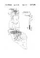
- FIG. 1is a perspective view, partially in section, of a hydrocephalus system employing a catheter tubing assembly according to the present invention and implanted within a patient.
- FIG. 2is an enlarged perspective view of the implanted hydrocephalus system of FIG. 1.
- FIG. 3is a perspective view of a ventricular catheter according to the present invention.
- FIG. 4is a generally schematic sketch illustrating a step in the manufacture of the porous portion of a ventricular catheter in accordance with this invention.
- FIG. 5is a cross-sectional view taken along the line 5--5 of FIG. 4.
- FIG. 6is a cross-sectional view along the line 6--6 of FIG. 5.
- FIG. 7is cross-sectional view of the porous portion of a tubing assembly according to the present invention and taken along the line 7--7 of FIG. 3.
- FIG. 8is a sketch of an exploded view of an external surface of a porous portion of a ventricular catheter prepared in accordance with the present invention at a magnification on the order of 150 times.
- a tubing assembly 10is shown as the catheter component of an implantable cerebrospinal fluid pressure relief system 12.
- a system 12is generally useful for the treatment of hydrocephalus by maintaining a desired predetermined intracranial pressure in a patient 14.
- the system 12includes a pressure relief valve 16 and a drain catheter 18.
- the system 12drains cerebrospinal fluid from a ventricle 20 of the brain 22.
- the cerebrospinal fluid 28occupies the volume of the ventricle, exiting therefrom through tubing assembly 10 and passing through the pressure relief valve 16 and drain catheter 18 for discharge into a selected portion the patient's body.
- the cerebrospinal fluidis discharged into a vein 24 which terminates within the right atrium of the heart 26.
- Other suitable drainage locationscan be selected, such as the peritoneal cavity.
- pressure relief valve 16includes means for adjusting the differential pressure threshold at which the valve 16 opens so that system 12 can be adjusted.
- various pressure relief valve assembliesare available. Particularly suitable to the practice of the present invention are those valves which are commercially available from Cordis Corporation. The dimensions of such valves are selected to be compatible with subcutaneous implantation over the patient's cranium.
- the tubing assembly 10is typically comprised of two smaller sections. Solid or non-porous section 32 extends down through the tissue of brain 22 and into the ventricle 20.
- right angle connector 34connects the tube assembly 10 to the rest of the system 12.
- Non-porous portion 32may be connected to right angle connector 34 by a suture 36, as shown.
- other connecting meansmay be employed such as, for example, heat or solvent reformation of the associated ends of connector 34 and section 32.
- the use of a right angle connector 34may be avoided as being unnecessary where there is no concern regarding pinching or kinking of the non-porous portion 32 as it exits the cranium 30 to connect with the pressure relief valve 16.
- porous portion 38is connected to non-porous portion 32.
- porous portion 38generally comprises the distal one-third portion of the tubing assembly 10.
- porous portion 38is provided with a surface containing a maximal number of extremely fine pores or inlet holes through which CSF will pass from the ventricle 20 into the tubing assembly 10. In this manner, the problem of pore blockage by ventricular collapse, tissue ingrowth and the like, is alleviated since the structure of the porous portion 38 provides a high surface density of extremely fine pores which are resistant to blockage. Additionally, the fine pore size will allow CSF to pass therethrough while simultaneously preventing tissue ingrowth under in vivo conditions. As further explained below in reference to FIGS.
- the pores of porous portion 38are formed by layers of overlapping polymeric fibers. Consequently, the pore structure of the porous portion 38 is actually a complex network of circuitous channels through which CSF can flow. It is believed that the small pore size coupled with the circuitous nature of the channel network both contribute to enhance the resistance of porous portion 38 to pore blockage by tissue ingrowth and the like.
- porous portion 38The actual manufacture of the porous portion 38 is discussed in more detail below. It is worth noting, however, that the choice of materials for manufacturing the porous portion 38 may also enhance the ability to resist tissue ingrowth. In general, materials with physical properties similar to those of polyurethanes are preferred. In this regard, polyurethanes are generally more lubricous than silastic, thereby contributing to an overall reduction in tissue adhesions when the assembly 10 is implanted in a ventricle 20.
- porous portion 38When initially manufactured, porous portion 38 is in the form of an open-ended tube. Heat or solvent reformation techniques, or their equivalents, are useful for bonding the porous portion 38 to non-porous portion 32 and for closing the free floating end of porous portion 38. In this manner, a biocompatible tubing assembly 10 is provided which is useful as a ventricular catheter and is substantially resistant to pore blockage under in vivo conditions.
- the apparatusincludes a distributor 40 for achieving formation of polymeric fibers 42.
- the distributor 40typically forms the fibers 42 by extrusion of a fiber-forming polymeric solution through one or more hypodermic cylinders 52. Before such fibers 42 are fully set, they are wound onto a mandrel 44 which is rotated within jaws 46. In the arrangement illustrated, the distributor 40 moves back and forth within a plane between the jaws 46, while the mandrel 44 is rotated by suitable means such as by motors 48. In this manner, the desired number of layers of polymeric fibers 42 are laid down over the mandrel 44.
- Electrostatic charge generation componentsmay be included in order to develop an electrostatic charge between the distributor 40 and the mandrel 44.
- the mandrel 44is grounded or negatively charged, while the distributor 40 is positively charged when a switch 50 or the like is closed.
- the distributor 40can be grounded and the mandrel 44 can be positively charged.
- polymeric fibers 42accelerate from the distributor 40 to the mandrel 44 faster than the acceleration achieved in the absence of the electrostatic field. Under selected conditions, such electrostatically accelerated fibers may be forced thereby into the interstices between the underlying fibers to form a surface with a desired pore size.
- an electrostatic charge of a predetermined magnitudemay aid in obtaining a porous portion 38 with a surface that has a very small pore size.
- Those skilled in the artwill appreciate that such results may be obtained by varying certain manufacturing parameters including the rate at which the distributor 40 moves back and forth between the jaws 46, the rate at which the mandrel 44 is rotated, the total amount of time an electrostatic charge is applied, and the particular polymer/solvent solution used to make the polymeric fibers 42.
- adjacent polymeric fibers 42each of which carry a like charge, tend to bow away from each other while in the gap between the cylinders 52 and the mandrel 44 as generally illustrated in FIG. 5.
- Distributor 40may include any number of individual extrusion orifices or hypodermic cylinders 52.
- Polymeric fibers 42when set, form a generally cylindrical porous portion 38 which has an inside diameter substantially the same as the outside diameter of the mandrel 44.
- Individual fibers 42are generally bonded to each other at the locations where the fibers intersect or otherwise contact each other. This fiber-to-fiber bonding results when the solvent-containing and partially set fibers 42 contact one another during winding and is typically facilitated by drawing the extruded fibers over other fibers lying thereunder. The actual bonding occurs upon removal of the solvent from the fibers 42, as by evaporation in air. Drawing of the fibers 42 is accomplished by selecting an appropriate speed of relative movement between the mandrel 44 and the distributor 40 thereby drawing the fibers 42 at a speed faster than the rate by which they are extruded from the distributor 40.
- Fiber breakagecan be remedied by the application of the electrostatic charge as soon as breakage occurs in order to accelerate the broken strand away from the hypodermic cylinder 52 so that the free end of the broken fiber contacts and adheres to the forming porous portion 38 which is facilitated by the rapid acceleration caused by the electrostatic force which directs the fiber 42 to the mandrel 44 and enhances the ability of the broken end to reach the porous portion 38 before the polymeric fibers 42 have set. Without application of the electrostatic field, the free end of the broken fiber typically will pendulum into the other fibers 42 causing additional fiber breakage.
- the polymeric material from which the fibers 42 are extrudedmust be a fiber forming type of polymer.
- a polymermust be capable of being formed as a fiber when extruded through a fine orifice, such as the hypodermic cylinders 52, and into the air.
- Polyamidessuch as the nylons and regenerated celulose products such as the rayons are fiber forming.
- the polyurethanestend to possess the physical properties desirable for the manufacture of ventricular catheters. Segmented polyurethanes, however, are typically not looked upon as being fiber forming in air, and when extruded they tend to exhibit excessive breakage. Nevertheless, polyurethanes of the type that are fiber forming are generally preferred.
- FIG. 7illustration is made of the structure of porous portion 38 viewed at a cross-section along the 7--7 line of FIG. 3.
- Fibers 42form distinct layers as determined by the number of passes of the distributor 40 over the mandrel 44.
- the overall thickness of the wall of porous portion 38is dependent both on the number of layers and on the thickness on the extruded fibers 42.
- the conditions under which the porous portion 38 is manufacturedcan be varied to achieve different effects. In the present application, conditions should be such so that the porous portion 38 will allow the passage of CSF therethrough while also creating pores 54 which are small enough to resist in vivo tissue ingrowth.
- such resultscan generally be obtained by formulation of the polymer solution to have a high solvent content and by extruding the polymer under electrostatic conditions. In this manner, the fibers 42 are accelerated onto the mandrel 44 at a high velocity and draw down ratio and impact on the mandrel 44 before significant solvent evaporation can occur. Electrostatic acceleration generally results in a flattening of the fibers 42 while simultaneously forcing these fibers 42 into the interstices between the underlying fibers.
- the exact manufacturing conditionssuch as the exact length of time during which the electrostatic charge is applied, will depend on the polymer/solvent solution employed as well as the apparatus utilized in extruding and winding the fibers 42.
- the size and shape of the poresmay be controlled by the angle subtended by the fibers 42 with respect to the mandrel 44 as well as the thickness of the extruded fibers 42.
- the use of an electrostatic chargeas is true of all other manufacturing parameters, will require some degree of judgment on the part of the operator in manufacturing the porous portion 38. Although the use of such a charge may be desirable in some instances, it may be totally inappropriate in other situations.
- each such manufacturing variablemust be considered in relation to the other manufacturing variables.
- the relative speed at which the distributor 40 moves back and forth, the use of and the need for an electrostatic field, and the likewill depend on the particular polymer/solvent solution used to the make the fibers 42 as well as on the various other manufacturing parameters.
- the preferred wall thickness of the tubing assembly 10is typically 0.025 inch.
- the size of pores 54 of porous portion 38should be such that CSF can flow into the tubing assembly 10 while the choroid plexus and other blocking means are excluded.
- FIG. 8shows a magnified section of a surface of porous portion 38 illustrating how fibers 42 form a network of interstitial pores through which CSF can flow.
Landscapes
- Health & Medical Sciences (AREA)
- Life Sciences & Earth Sciences (AREA)
- Engineering & Computer Science (AREA)
- Heart & Thoracic Surgery (AREA)
- Animal Behavior & Ethology (AREA)
- Public Health (AREA)
- Biomedical Technology (AREA)
- Hematology (AREA)
- Anesthesiology (AREA)
- Veterinary Medicine (AREA)
- General Health & Medical Sciences (AREA)
- Pulmonology (AREA)
- Biophysics (AREA)
- Vascular Medicine (AREA)
- Surgery (AREA)
- Mechanical Engineering (AREA)
- Materials For Medical Uses (AREA)
- External Artificial Organs (AREA)
Abstract
Description
Claims (29)
Priority Applications (1)
| Application Number | Priority Date | Filing Date | Title |
|---|---|---|---|
| US07/113,884US4767400A (en) | 1987-10-27 | 1987-10-27 | Porous ventricular catheter |
Applications Claiming Priority (1)
| Application Number | Priority Date | Filing Date | Title |
|---|---|---|---|
| US07/113,884US4767400A (en) | 1987-10-27 | 1987-10-27 | Porous ventricular catheter |
Publications (1)
| Publication Number | Publication Date |
|---|---|
| US4767400Atrue US4767400A (en) | 1988-08-30 |
Family
ID=22352103
Family Applications (1)
| Application Number | Title | Priority Date | Filing Date |
|---|---|---|---|
| US07/113,884Expired - LifetimeUS4767400A (en) | 1987-10-27 | 1987-10-27 | Porous ventricular catheter |
Country Status (1)
| Country | Link |
|---|---|
| US (1) | US4767400A (en) |
Cited By (83)
| Publication number | Priority date | Publication date | Assignee | Title |
|---|---|---|---|---|
| US4936825A (en)* | 1988-04-11 | 1990-06-26 | Ungerleider Bruce A | Method for reducing intraocular pressure caused by glaucoma |
| US4950224A (en)* | 1988-08-05 | 1990-08-21 | Healthdyne, Inc. | Apparatus and method for in vivo plasma separation |
| WO1992000112A1 (en)* | 1990-06-25 | 1992-01-09 | Ungerleider Bruce A | Apparatus for reducing intraocular pressure |
| EP0474870A4 (en)* | 1990-03-27 | 1992-09-09 | Poltavsky Meditsinsky Stomatologichesky Institut | Drainage tube |
| US5151082A (en)* | 1988-08-05 | 1992-09-29 | Heathdyne, Inc. | Apparatus and method for kidney dialysis using plasma in lieu of blood |
| US5152743A (en)* | 1988-08-05 | 1992-10-06 | Healthdyne, Inc. | Apparatus and method for selective separation of blood cholesterol |
| US5176626A (en)* | 1992-01-15 | 1993-01-05 | Wilson-Cook Medical, Inc. | Indwelling stent |
| EP0511499A3 (en)* | 1991-04-02 | 1993-03-24 | Advanced Cardiovascular System | Method and catheter for controlled intravascular drug delivery |
| EP0536296A4 (en)* | 1990-06-26 | 1993-08-04 | Cardiovascular Therapeutic Technologies, Inc. | Method and catheter for intravascular drug delivery |
| US5242382A (en)* | 1988-08-05 | 1993-09-07 | Healthdyne, Inc. | Apparatus and method for direct measurement of blood parameters |
| US5338291A (en)* | 1993-02-03 | 1994-08-16 | Pudenz-Schulte Medical Research Corporation | Glaucoma shunt and method for draining aqueous humor |
| US5385541A (en)* | 1992-04-24 | 1995-01-31 | Loma Linda University Medical Center | Cerebrospinal fluid shunt capable of minimal invasive revision |
| US5405316A (en)* | 1993-11-17 | 1995-04-11 | Magram; Gary | Cerebrospinal fluid shunt |
| US5462523A (en)* | 1993-05-18 | 1995-10-31 | Target Therapeutics, Inc. | Drug delivery system |
| US5487739A (en)* | 1987-11-17 | 1996-01-30 | Brown University Research Foundation | Implantable therapy systems and methods |
| WO1996021477A1 (en)* | 1995-01-14 | 1996-07-18 | Michael Volkmer | Surgical suction instrument |
| US5547472A (en)* | 1994-01-20 | 1996-08-20 | Terumo Kabushiki Kaisha | Catheter with medicament injection pores |
| US5800390A (en)* | 1991-05-24 | 1998-09-01 | Sumitomo Pharmaceuticals Company, Limited | Equipment for intracerebral administration of preparations |
| US5810398A (en)* | 1992-10-02 | 1998-09-22 | Pall Corporation | Fluid delivery systems and methods and assemblies for making connections |
| US5868433A (en)* | 1992-10-02 | 1999-02-09 | Pall Corporation | Connector assembly |
| US6056725A (en)* | 1996-04-30 | 2000-05-02 | Medtronic, Inc. | Therapeutic method for treatment of alzheimer's disease |
| US6059767A (en)* | 1998-02-25 | 2000-05-09 | Norborn Medical, Inc. | Steerable unitary infusion catheter/guide wire incorporating detachable infusion port assembly |
| US6093180A (en)* | 1995-04-28 | 2000-07-25 | Medtronic, Inc. | Intraparenchymal infusion catheter system |
| US6336924B1 (en)* | 1997-12-17 | 2002-01-08 | Nmt Neurosciences Implants S.A. | External biological fluid drainage device |
| US20020191650A1 (en)* | 2001-02-26 | 2002-12-19 | Madey John M. J. | Phase displacement free-electron laser |
| US20030135148A1 (en)* | 2002-01-14 | 2003-07-17 | Dextradeur Alan J. | Multi-catheter insertion device and method |
| US6594880B2 (en)* | 1995-04-28 | 2003-07-22 | Medtronic, Inc. | Intraparenchymal infusion catheter system |
| US6655655B1 (en) | 1997-05-09 | 2003-12-02 | Pall Corporation | Connector assemblies, fluid systems, and methods for making a connection |
| US20040087887A1 (en)* | 2000-10-30 | 2004-05-06 | Nilsson Per Erik | System and method for physiological drainage |
| US6746422B1 (en) | 2000-08-23 | 2004-06-08 | Norborn Medical, Inc. | Steerable support system with external ribs/slots that taper |
| US20040220547A1 (en)* | 2002-12-23 | 2004-11-04 | Medtronic, Inc | Multiple infusion section catheters, systems, and methods |
| US20040236309A1 (en)* | 2003-05-19 | 2004-11-25 | Benson Yang | Mesh ventricular catheter with antithrombogenic coating |
| US20040265796A1 (en)* | 2003-04-17 | 2004-12-30 | Thomas Briese | Methods and kits for detecting SARS-associated coronavirus |
| US20050027234A1 (en)* | 2003-06-18 | 2005-02-03 | Waggoner Donna Jean | Surgical implant and method of accessing cerebrospinal fluid |
| US20050059922A1 (en)* | 2003-08-01 | 2005-03-17 | Kuhlman Steven Michael | Surgical implant and method of accessing cerebrospinal fluid |
| US20050113853A1 (en)* | 2000-04-06 | 2005-05-26 | Norborn Medical, Inc. | Guidewire for crossing occlusions or stenoses |
| US20050113802A1 (en)* | 2001-03-01 | 2005-05-26 | Watson David A. | Process for creating an ingrowth preventing indwelling catheter assembly |
| US20050119603A1 (en)* | 2003-11-04 | 2005-06-02 | Kuhlman Steven M. | Surgical implant for accessing cerebrospinal fluid and method of surgically inserting same |
| US20050119615A1 (en)* | 2000-04-06 | 2005-06-02 | Norborn Medical, Inc. | Guidewire for crossing occlusions or stenoses |
| US20050137578A1 (en)* | 2002-12-23 | 2005-06-23 | Medtronic, Inc. | Catheters incorporating valves and permeable membranes |
| US20050137579A1 (en)* | 2003-12-23 | 2005-06-23 | Medtronic, Inc. | Permeable membrane catheters, systems, and methods |
| US20060074388A1 (en)* | 2004-09-30 | 2006-04-06 | Alan Dextradeur | Fluid management flow implants of improved occlusion resistance |
| US20060074442A1 (en)* | 2000-04-06 | 2006-04-06 | Revascular Therapeutics, Inc. | Guidewire for crossing occlusions or stenoses |
| US7037288B2 (en) | 2002-01-14 | 2006-05-02 | Codman & Shurtleff, Inc. | Anti-block catheter |
| WO2007014028A1 (en)* | 2005-07-21 | 2007-02-01 | The Cleveland Clinic Foundation | Medical oscillating compliance devices and uses thereof |
| US7189222B2 (en) | 1996-04-30 | 2007-03-13 | Medtronic, Inc. | Therapeutic method of treatment of alzheimer's disease |
| US20070225615A1 (en)* | 2006-03-22 | 2007-09-27 | Revascular Therapeutics Inc. | Guidewire controller system |
| US7381198B2 (en) | 2000-08-23 | 2008-06-03 | Revascular Therapeutics, Inc. | Steerable distal support system |
| US20080140101A1 (en)* | 2006-12-07 | 2008-06-12 | Revascular Therapeutic, Inc. | Apparatus for crossing occlusions or stenoses |
| US20080171990A1 (en)* | 2006-10-28 | 2008-07-17 | Alois Zauner | Multimodal Catheter for Focal Brain Monitoring and Ventriculostomy |
| US20080221601A1 (en)* | 1998-02-25 | 2008-09-11 | Revascular Therapeutics, Inc. | Guidewire for crossing occlusions or stenoses having a shapeable distal end |
| WO2009036039A1 (en)* | 2007-09-10 | 2009-03-19 | Sevrain Lionel C | Anti-clogging ventricular catheter using a membrane for cerebrospinal fluid drainage |
| US20090125080A1 (en)* | 2007-11-12 | 2009-05-14 | Montgomery Jr Erwin B | Intraventricular electrodes for electrical stimulation of the brain |
| WO2010031515A1 (en)* | 2008-09-17 | 2010-03-25 | Johanneum Research Forschungsgesellschaft Mbh | Filament-based catheter |
| US20100089402A1 (en)* | 2007-01-24 | 2010-04-15 | Stephen James Field | Medico-surgical devices |
| US20100114006A1 (en)* | 2008-11-05 | 2010-05-06 | Advanced Medical Optics, Inc. | Glaucoma drainage shunts and methods of use |
| US20100113967A1 (en)* | 2008-10-24 | 2010-05-06 | Innerspace, Inc. | Catheter with pressure sensor |
| US20100249691A1 (en)* | 2009-03-26 | 2010-09-30 | Abbott Medical Optics Inc. | Glaucoma shunts with flow management and improved surgical performance |
| US20100249747A1 (en)* | 2009-03-26 | 2010-09-30 | Organic Medical Ventures, L.L.C. | Transdermal venous access locking solution |
| US7815626B1 (en) | 1998-06-12 | 2010-10-19 | Target Therapeutics, Inc. | Catheter with knit section |
| US20110004158A1 (en)* | 2007-11-02 | 2011-01-06 | Luciano Mark G | Device for increasing cerebral blood flow |
| US20110190731A1 (en)* | 1999-07-19 | 2011-08-04 | I-Flow | Method for Fluid Delivery and Catheters for Use with Same |
| US8162891B2 (en) | 2008-11-26 | 2012-04-24 | Revascular Therapeutics, Inc. | Delivery and exchange catheter for storing guidewire |
| US8246602B2 (en) | 2002-12-23 | 2012-08-21 | Medtronic, Inc. | Catheters with tracking elements and permeable membranes |
| WO2013032464A1 (en) | 2011-08-31 | 2013-03-07 | Organic Medical Ventures, L.L.C. | Transdermal venous access locking solutions |
| US8454059B2 (en) | 2010-09-13 | 2013-06-04 | Pall Corporation | Connector assemblies, fluid systems including connector assemblies, and procedures for making fluid connections |
| US8657821B2 (en) | 2008-11-14 | 2014-02-25 | Revascular Therapeutics Inc. | Method and system for reversibly controlled drilling of luminal occlusions |
| US9072296B2 (en) | 2009-03-26 | 2015-07-07 | Organic Medical Ventures, L.L.C. | Transdermal venous access locking solutions |
| US9295821B2 (en) | 2008-07-02 | 2016-03-29 | Christoph Miethke | Cerebrospinal fluid drainage |
| US9427498B2 (en) | 2009-03-26 | 2016-08-30 | Organic Medical Ventures, L.L.C. | Syringe treated with transdermal venous access locking solutions and method of treating the syringe |
| US9433209B2 (en) | 2009-03-26 | 2016-09-06 | Organic Medical Ventures, L.L.C. | Transdermal venous access locking solutions |
| WO2016168505A1 (en)* | 2015-04-16 | 2016-10-20 | Stryker Corporation | System and method for manufacturing variable stiffness catheters |
| US9694166B2 (en) | 2002-03-26 | 2017-07-04 | Medtronics Ps Medical, Inc. | Method of draining cerebrospinal fluid |
| USD824042S1 (en)* | 2016-11-10 | 2018-07-24 | Viacyte, Inc. | Perforated cell encapsulation device |
| US10183143B2 (en) | 2013-03-15 | 2019-01-22 | Bitol Designs, Llc | Occlusion resistant catheter and method of use |
| WO2019035020A1 (en) | 2017-08-18 | 2019-02-21 | Aljazaeri Ayman Hassan A | Drainage catheter with retractable internal drains |
| US10232151B2 (en) | 2010-09-29 | 2019-03-19 | Integra Lifesciences Switzerland Sàrl | Multi-lumen ventricular drainage catheter |
| US10518069B2 (en) | 2016-10-28 | 2019-12-31 | Integra LifeSciences Switzerland Sarl | Implantable valve assembly with extended lifespan |
| US10765847B1 (en) | 2019-12-10 | 2020-09-08 | Ayman H. Al-Jazaeri | Single lumen drainage catheter with extendable and retractable drains |
| WO2023034604A1 (en)* | 2021-09-03 | 2023-03-09 | Freeflow Medical Devices Llc | Hydrocephalus shunt |
| US11672701B2 (en) | 2018-10-25 | 2023-06-13 | Amo Groningen B.V. | Bleb control glaucoma shunts |
| US20230310815A1 (en)* | 2022-04-05 | 2023-10-05 | The Board Of Trustees Of The University Of Illinois | Proximal ventriculoperitoneal shunt with retractable mesh |
| IT202200021135A1 (en)* | 2022-10-13 | 2024-04-13 | Claudia Piscitelli | SURGICAL DEVICE FOR BRAIN HERNIATION |
Citations (6)
| Publication number | Priority date | Publication date | Assignee | Title |
|---|---|---|---|---|
| US3773034A (en)* | 1971-11-24 | 1973-11-20 | Itt Research Institute | Steerable catheter |
| US4377169A (en)* | 1981-06-10 | 1983-03-22 | Banks Bruce A | Ion beam sputter-etched ventricular catheter for hydrocephalus shunt |
| US4475972A (en)* | 1981-10-01 | 1984-10-09 | Ontario Research Foundation | Implantable material |
| US4507119A (en)* | 1982-07-06 | 1985-03-26 | E. I. Du Pont De Nemours And Company | Sterile docking process, apparatus and system |
| US4601724A (en)* | 1984-05-29 | 1986-07-22 | Cordis Corporation | Manufacture of tubing assembly for drainage catheter |
| US4650466A (en)* | 1985-11-01 | 1987-03-17 | Angiobrade Partners | Angioplasty device |
- 1987
- 1987-10-27USUS07/113,884patent/US4767400A/ennot_activeExpired - Lifetime
Patent Citations (6)
| Publication number | Priority date | Publication date | Assignee | Title |
|---|---|---|---|---|
| US3773034A (en)* | 1971-11-24 | 1973-11-20 | Itt Research Institute | Steerable catheter |
| US4377169A (en)* | 1981-06-10 | 1983-03-22 | Banks Bruce A | Ion beam sputter-etched ventricular catheter for hydrocephalus shunt |
| US4475972A (en)* | 1981-10-01 | 1984-10-09 | Ontario Research Foundation | Implantable material |
| US4507119A (en)* | 1982-07-06 | 1985-03-26 | E. I. Du Pont De Nemours And Company | Sterile docking process, apparatus and system |
| US4601724A (en)* | 1984-05-29 | 1986-07-22 | Cordis Corporation | Manufacture of tubing assembly for drainage catheter |
| US4650466A (en)* | 1985-11-01 | 1987-03-17 | Angiobrade Partners | Angioplasty device |
Cited By (141)
| Publication number | Priority date | Publication date | Assignee | Title |
|---|---|---|---|---|
| US5487739A (en)* | 1987-11-17 | 1996-01-30 | Brown University Research Foundation | Implantable therapy systems and methods |
| US5372577A (en)* | 1988-04-11 | 1994-12-13 | Ungerleider; Bruce A. | Apparatus for reducing intraocular pressure |
| US4936825A (en)* | 1988-04-11 | 1990-06-26 | Ungerleider Bruce A | Method for reducing intraocular pressure caused by glaucoma |
| US5242382A (en)* | 1988-08-05 | 1993-09-07 | Healthdyne, Inc. | Apparatus and method for direct measurement of blood parameters |
| US4950224A (en)* | 1988-08-05 | 1990-08-21 | Healthdyne, Inc. | Apparatus and method for in vivo plasma separation |
| US5151082A (en)* | 1988-08-05 | 1992-09-29 | Heathdyne, Inc. | Apparatus and method for kidney dialysis using plasma in lieu of blood |
| US5152743A (en)* | 1988-08-05 | 1992-10-06 | Healthdyne, Inc. | Apparatus and method for selective separation of blood cholesterol |
| EP0474870A4 (en)* | 1990-03-27 | 1992-09-09 | Poltavsky Meditsinsky Stomatologichesky Institut | Drainage tube |
| WO1992000112A1 (en)* | 1990-06-25 | 1992-01-09 | Ungerleider Bruce A | Apparatus for reducing intraocular pressure |
| EP0536296A4 (en)* | 1990-06-26 | 1993-08-04 | Cardiovascular Therapeutic Technologies, Inc. | Method and catheter for intravascular drug delivery |
| EP0511499A3 (en)* | 1991-04-02 | 1993-03-24 | Advanced Cardiovascular System | Method and catheter for controlled intravascular drug delivery |
| US5800390A (en)* | 1991-05-24 | 1998-09-01 | Sumitomo Pharmaceuticals Company, Limited | Equipment for intracerebral administration of preparations |
| US5176626A (en)* | 1992-01-15 | 1993-01-05 | Wilson-Cook Medical, Inc. | Indwelling stent |
| USRE35849E (en)* | 1992-01-15 | 1998-07-14 | Wilson-Cook Medical, Inc. | Indwelling stent |
| US5385541A (en)* | 1992-04-24 | 1995-01-31 | Loma Linda University Medical Center | Cerebrospinal fluid shunt capable of minimal invasive revision |
| US5868433A (en)* | 1992-10-02 | 1999-02-09 | Pall Corporation | Connector assembly |
| US5810398A (en)* | 1992-10-02 | 1998-09-22 | Pall Corporation | Fluid delivery systems and methods and assemblies for making connections |
| US6536805B2 (en) | 1992-10-02 | 2003-03-25 | Pall Corporation | Fluid delivery systems and methods and assemblies for making connections |
| US6341802B1 (en) | 1992-10-02 | 2002-01-29 | Pall Corporation | Fluid delivery systems and methods and assemblies for making connections |
| US5338291A (en)* | 1993-02-03 | 1994-08-16 | Pudenz-Schulte Medical Research Corporation | Glaucoma shunt and method for draining aqueous humor |
| US5462523A (en)* | 1993-05-18 | 1995-10-31 | Target Therapeutics, Inc. | Drug delivery system |
| US5405316A (en)* | 1993-11-17 | 1995-04-11 | Magram; Gary | Cerebrospinal fluid shunt |
| US5547472A (en)* | 1994-01-20 | 1996-08-20 | Terumo Kabushiki Kaisha | Catheter with medicament injection pores |
| WO1996021477A1 (en)* | 1995-01-14 | 1996-07-18 | Michael Volkmer | Surgical suction instrument |
| US6594880B2 (en)* | 1995-04-28 | 2003-07-22 | Medtronic, Inc. | Intraparenchymal infusion catheter system |
| US7069634B1 (en) | 1995-04-28 | 2006-07-04 | Medtronic, Inc. | Method for manufacturing a catheter |
| US6093180A (en)* | 1995-04-28 | 2000-07-25 | Medtronic, Inc. | Intraparenchymal infusion catheter system |
| US6056725A (en)* | 1996-04-30 | 2000-05-02 | Medtronic, Inc. | Therapeutic method for treatment of alzheimer's disease |
| US6503242B1 (en) | 1996-04-30 | 2003-01-07 | Medtronic, Inc. | Therapeutic method for treatment of Alzheimer's disease |
| US7189222B2 (en) | 1996-04-30 | 2007-03-13 | Medtronic, Inc. | Therapeutic method of treatment of alzheimer's disease |
| US6655655B1 (en) | 1997-05-09 | 2003-12-02 | Pall Corporation | Connector assemblies, fluid systems, and methods for making a connection |
| US6336924B1 (en)* | 1997-12-17 | 2002-01-08 | Nmt Neurosciences Implants S.A. | External biological fluid drainage device |
| US9254143B2 (en) | 1998-02-25 | 2016-02-09 | Revascular Therapeutics, Inc. | Guidewire for crossing occlusions or stenoses having a shapeable distal end |
| US20080221601A1 (en)* | 1998-02-25 | 2008-09-11 | Revascular Therapeutics, Inc. | Guidewire for crossing occlusions or stenoses having a shapeable distal end |
| US6059767A (en)* | 1998-02-25 | 2000-05-09 | Norborn Medical, Inc. | Steerable unitary infusion catheter/guide wire incorporating detachable infusion port assembly |
| US7815626B1 (en) | 1998-06-12 | 2010-10-19 | Target Therapeutics, Inc. | Catheter with knit section |
| US8181324B2 (en) | 1998-06-12 | 2012-05-22 | Target Therapeutics, Inc. | Catheter with knit section |
| US20110024025A1 (en)* | 1998-06-12 | 2011-02-03 | Target Therapeutics, Inc. | Catheter With Knit Section |
| US8328771B2 (en)* | 1999-07-19 | 2012-12-11 | Roger Dillard Massengale | Method for fluid delivery and catheters for use with same |
| US20110190731A1 (en)* | 1999-07-19 | 2011-08-04 | I-Flow | Method for Fluid Delivery and Catheters for Use with Same |
| US8043314B2 (en) | 2000-04-06 | 2011-10-25 | Revascular Therapeutics Inc. | Guidewire for crossing occlusions or stenoses |
| US7628763B2 (en) | 2000-04-06 | 2009-12-08 | Revascular Therapeutics, Inc. | Guidewire for crossing occlusions or stenoses |
| US9113955B2 (en) | 2000-04-06 | 2015-08-25 | Revascular Therapeutics, Inc. | Guidewire for crossing occlusions or stenoses |
| US8747332B2 (en) | 2000-04-06 | 2014-06-10 | Revascular Therapeutics Inc. | Guidewire for crossing occlusions or stenoses |
| US8043312B2 (en) | 2000-04-06 | 2011-10-25 | Revascular Therapeutics Inc. | Guidewire for crossing occlusions or stenoses |
| US20050113853A1 (en)* | 2000-04-06 | 2005-05-26 | Norborn Medical, Inc. | Guidewire for crossing occlusions or stenoses |
| US20100049169A1 (en)* | 2000-04-06 | 2010-02-25 | Revascular Therapeutics, Inc. | Guidewire for crossing occlusions or stenoses |
| US20050228418A1 (en)* | 2000-04-06 | 2005-10-13 | Revascular Therapeutics Inc. | Guidewire for crossing occlusions or stenoses |
| US20050119615A1 (en)* | 2000-04-06 | 2005-06-02 | Norborn Medical, Inc. | Guidewire for crossing occlusions or stenoses |
| US20060074442A1 (en)* | 2000-04-06 | 2006-04-06 | Revascular Therapeutics, Inc. | Guidewire for crossing occlusions or stenoses |
| US7381198B2 (en) | 2000-08-23 | 2008-06-03 | Revascular Therapeutics, Inc. | Steerable distal support system |
| US6746422B1 (en) | 2000-08-23 | 2004-06-08 | Norborn Medical, Inc. | Steerable support system with external ribs/slots that taper |
| US7476211B2 (en) | 2000-10-30 | 2009-01-13 | Technovobis Ab | System and method for physiological drainage |
| US20040087887A1 (en)* | 2000-10-30 | 2004-05-06 | Nilsson Per Erik | System and method for physiological drainage |
| US20020191650A1 (en)* | 2001-02-26 | 2002-12-19 | Madey John M. J. | Phase displacement free-electron laser |
| US20100179471A1 (en)* | 2001-03-01 | 2010-07-15 | Watson David A | Ingrowth preventing indwelling catheter assembly |
| US8376980B2 (en) | 2001-03-01 | 2013-02-19 | David A. Watson | Ingrowth preventing indwelling catheter assembly |
| US7763142B2 (en) | 2001-03-01 | 2010-07-27 | Watson David A | Process for creating an ingrowth preventing indwelling catheter assembly |
| US20100282394A1 (en)* | 2001-03-01 | 2010-11-11 | Watson David A | Process for creating an ingrowth preventing indwelling catheter assembly |
| US20050113802A1 (en)* | 2001-03-01 | 2005-05-26 | Watson David A. | Process for creating an ingrowth preventing indwelling catheter assembly |
| US20030135148A1 (en)* | 2002-01-14 | 2003-07-17 | Dextradeur Alan J. | Multi-catheter insertion device and method |
| US7037288B2 (en) | 2002-01-14 | 2006-05-02 | Codman & Shurtleff, Inc. | Anti-block catheter |
| US6913589B2 (en) | 2002-01-14 | 2005-07-05 | Codman & Shurtleff, Inc. | Multi-catheter insertion device and method |
| US7699800B2 (en) | 2002-01-14 | 2010-04-20 | Codman & Shurtleff, Inc. | Multi-catheter insertion device and method |
| US20050159697A1 (en)* | 2002-01-14 | 2005-07-21 | Codman & Shurtleff, Inc. | Multi-catheter insertion device and method |
| US9694166B2 (en) | 2002-03-26 | 2017-07-04 | Medtronics Ps Medical, Inc. | Method of draining cerebrospinal fluid |
| US20040220546A1 (en)* | 2002-12-23 | 2004-11-04 | Medtronic, Inc. | Reduction of inflammatory mass with spinal catheters |
| US8216177B2 (en) | 2002-12-23 | 2012-07-10 | Medtronic, Inc. | Implantable drug delivery systems and methods |
| US20050137578A1 (en)* | 2002-12-23 | 2005-06-23 | Medtronic, Inc. | Catheters incorporating valves and permeable membranes |
| US20040220543A1 (en)* | 2002-12-23 | 2004-11-04 | Medtronic, Inc. | Trailing system for evaluation of the efficacy of the treatment |
| US20040220552A1 (en)* | 2002-12-23 | 2004-11-04 | Medtronic, Inc. | Implantable drug delivery systems and methods |
| US20040220547A1 (en)* | 2002-12-23 | 2004-11-04 | Medtronic, Inc | Multiple infusion section catheters, systems, and methods |
| US7662140B2 (en)* | 2002-12-23 | 2010-02-16 | Medtronic, Inc. | Method of delivering drug to brain via spinal cord |
| US20040220518A1 (en)* | 2002-12-23 | 2004-11-04 | Medtronic, Inc. | Drug solution density adjustment systems and methods |
| US8246602B2 (en) | 2002-12-23 | 2012-08-21 | Medtronic, Inc. | Catheters with tracking elements and permeable membranes |
| US20040220545A1 (en)* | 2002-12-23 | 2004-11-04 | Medtronic, Inc. | Method of delivering drugs to specific regions of the spinal cord |
| US8043281B2 (en) | 2002-12-23 | 2011-10-25 | Medtronic, Inc. | Catheters incorporating valves and permeable membranes |
| US8137334B2 (en) | 2002-12-23 | 2012-03-20 | Medtronic, Inc. | Reduction of inflammatory mass with spinal catheters |
| US20040220544A1 (en)* | 2002-12-23 | 2004-11-04 | Medtronic, Inc. | Method of delivering drug to brain via spinal cord |
| US20040265796A1 (en)* | 2003-04-17 | 2004-12-30 | Thomas Briese | Methods and kits for detecting SARS-associated coronavirus |
| US20040236309A1 (en)* | 2003-05-19 | 2004-11-25 | Benson Yang | Mesh ventricular catheter with antithrombogenic coating |
| US20050027234A1 (en)* | 2003-06-18 | 2005-02-03 | Waggoner Donna Jean | Surgical implant and method of accessing cerebrospinal fluid |
| US20050059922A1 (en)* | 2003-08-01 | 2005-03-17 | Kuhlman Steven Michael | Surgical implant and method of accessing cerebrospinal fluid |
| US20050119603A1 (en)* | 2003-11-04 | 2005-06-02 | Kuhlman Steven M. | Surgical implant for accessing cerebrospinal fluid and method of surgically inserting same |
| US20050137579A1 (en)* | 2003-12-23 | 2005-06-23 | Medtronic, Inc. | Permeable membrane catheters, systems, and methods |
| US7976517B2 (en) | 2004-09-30 | 2011-07-12 | Codman & Shurtleff, Inc. | Fluid management flow implants of improved occlusion resistance |
| US8221392B2 (en) | 2004-09-30 | 2012-07-17 | Codman & Shurtleff, Inc. | Fluid management flow implants of improved occlusion resistance |
| US20080214982A1 (en)* | 2004-09-30 | 2008-09-04 | Alan Dextradeur | Fluid management flow implants of improved occlusion resistance |
| US20060074388A1 (en)* | 2004-09-30 | 2006-04-06 | Alan Dextradeur | Fluid management flow implants of improved occlusion resistance |
| US20090177279A1 (en)* | 2005-07-21 | 2009-07-09 | The Cleveland Clinic Foundation | Medical oscillating compliance devices and uses thereof |
| US8956379B2 (en) | 2005-07-21 | 2015-02-17 | The Cleveland Clinic Foundation | Medical oscillating compliance devices and uses thereof |
| WO2007014028A1 (en)* | 2005-07-21 | 2007-02-01 | The Cleveland Clinic Foundation | Medical oscillating compliance devices and uses thereof |
| US20070225615A1 (en)* | 2006-03-22 | 2007-09-27 | Revascular Therapeutics Inc. | Guidewire controller system |
| US20080171990A1 (en)* | 2006-10-28 | 2008-07-17 | Alois Zauner | Multimodal Catheter for Focal Brain Monitoring and Ventriculostomy |
| US7776003B2 (en) | 2006-10-28 | 2010-08-17 | Alois Zauner | Multimodal catheter for focal brain monitoring and ventriculostomy |
| US20080140101A1 (en)* | 2006-12-07 | 2008-06-12 | Revascular Therapeutic, Inc. | Apparatus for crossing occlusions or stenoses |
| US20100089402A1 (en)* | 2007-01-24 | 2010-04-15 | Stephen James Field | Medico-surgical devices |
| US8584677B2 (en)* | 2007-01-24 | 2013-11-19 | Smiths Group Plc | Medico-surgical devices |
| US8827944B2 (en)* | 2007-09-10 | 2014-09-09 | Lers Surgical, Llc | Anti-clogging ventricular catheter for cerebrospinal fluid drainage |
| WO2009036039A1 (en)* | 2007-09-10 | 2009-03-19 | Sevrain Lionel C | Anti-clogging ventricular catheter using a membrane for cerebrospinal fluid drainage |
| US20100222732A1 (en)* | 2007-09-10 | 2010-09-02 | Sevrain Lionel C | Anti-clogging ventricular catheter for cerebrospinal fluid drainage |
| US9011378B2 (en) | 2007-11-02 | 2015-04-21 | The Cleveland Clinic Foundation | Device for increasing cerebral blood flow |
| US20110004158A1 (en)* | 2007-11-02 | 2011-01-06 | Luciano Mark G | Device for increasing cerebral blood flow |
| US20090125080A1 (en)* | 2007-11-12 | 2009-05-14 | Montgomery Jr Erwin B | Intraventricular electrodes for electrical stimulation of the brain |
| US9295821B2 (en) | 2008-07-02 | 2016-03-29 | Christoph Miethke | Cerebrospinal fluid drainage |
| US9039665B2 (en) | 2008-09-17 | 2015-05-26 | Joanneum Research Forschungsgesellschaft Mbh | Filament-based catheter |
| WO2010031515A1 (en)* | 2008-09-17 | 2010-03-25 | Johanneum Research Forschungsgesellschaft Mbh | Filament-based catheter |
| US20110224628A1 (en)* | 2008-09-17 | 2011-09-15 | Manfred Bodenlenz | Filament-Based Catheter |
| US20100113967A1 (en)* | 2008-10-24 | 2010-05-06 | Innerspace, Inc. | Catheter with pressure sensor |
| US10492948B2 (en) | 2008-11-05 | 2019-12-03 | Johnson & Johnson Surgical Vision, Inc. | Glaucoma drainage shunts and methods of use |
| US8353856B2 (en) | 2008-11-05 | 2013-01-15 | Abbott Medical Optics Inc. | Glaucoma drainage shunts and methods of use |
| US9468558B2 (en) | 2008-11-05 | 2016-10-18 | Abbott Medical Optics Inc. | Glaucoma drainage shunts and methods of use |
| US20100114006A1 (en)* | 2008-11-05 | 2010-05-06 | Advanced Medical Optics, Inc. | Glaucoma drainage shunts and methods of use |
| US8920357B2 (en) | 2008-11-05 | 2014-12-30 | Abbott Medical Optics Inc. | Glaucoma drainage shunts and methods of use |
| US8657821B2 (en) | 2008-11-14 | 2014-02-25 | Revascular Therapeutics Inc. | Method and system for reversibly controlled drilling of luminal occlusions |
| US9820770B2 (en) | 2008-11-14 | 2017-11-21 | Boston Scientific Scimed, Inc. | Method and system for reversibly controlled drilling of luminal occlusions |
| US8162891B2 (en) | 2008-11-26 | 2012-04-24 | Revascular Therapeutics, Inc. | Delivery and exchange catheter for storing guidewire |
| US8801691B2 (en) | 2008-11-26 | 2014-08-12 | Revascular Therapeutics, Inc. | Delivery and exchange catheter for storing guidewire |
| US9433209B2 (en) | 2009-03-26 | 2016-09-06 | Organic Medical Ventures, L.L.C. | Transdermal venous access locking solutions |
| US9380780B2 (en) | 2009-03-26 | 2016-07-05 | Organic Medical Ventures, L.L.C. | Transdermal venous access locking solutions |
| US9427498B2 (en) | 2009-03-26 | 2016-08-30 | Organic Medical Ventures, L.L.C. | Syringe treated with transdermal venous access locking solutions and method of treating the syringe |
| US20100249691A1 (en)* | 2009-03-26 | 2010-09-30 | Abbott Medical Optics Inc. | Glaucoma shunts with flow management and improved surgical performance |
| US9072296B2 (en) | 2009-03-26 | 2015-07-07 | Organic Medical Ventures, L.L.C. | Transdermal venous access locking solutions |
| US8702639B2 (en) | 2009-03-26 | 2014-04-22 | Abbott Medical Optics Inc. | Glaucoma shunts with flow management and improved surgical performance |
| US20100249747A1 (en)* | 2009-03-26 | 2010-09-30 | Organic Medical Ventures, L.L.C. | Transdermal venous access locking solution |
| US8454059B2 (en) | 2010-09-13 | 2013-06-04 | Pall Corporation | Connector assemblies, fluid systems including connector assemblies, and procedures for making fluid connections |
| US10232151B2 (en) | 2010-09-29 | 2019-03-19 | Integra Lifesciences Switzerland Sàrl | Multi-lumen ventricular drainage catheter |
| WO2013032464A1 (en) | 2011-08-31 | 2013-03-07 | Organic Medical Ventures, L.L.C. | Transdermal venous access locking solutions |
| US10183143B2 (en) | 2013-03-15 | 2019-01-22 | Bitol Designs, Llc | Occlusion resistant catheter and method of use |
| US10426917B2 (en) | 2015-04-16 | 2019-10-01 | Stryker Corporation | System and method for manufacturing variable stiffness catheters |
| WO2016168505A1 (en)* | 2015-04-16 | 2016-10-20 | Stryker Corporation | System and method for manufacturing variable stiffness catheters |
| US10518069B2 (en) | 2016-10-28 | 2019-12-31 | Integra LifeSciences Switzerland Sarl | Implantable valve assembly with extended lifespan |
| USD824042S1 (en)* | 2016-11-10 | 2018-07-24 | Viacyte, Inc. | Perforated cell encapsulation device |
| WO2019035020A1 (en) | 2017-08-18 | 2019-02-21 | Aljazaeri Ayman Hassan A | Drainage catheter with retractable internal drains |
| US10500331B2 (en) | 2017-08-18 | 2019-12-10 | Ayman H. Al-Jazaeri | Drainage catheter with retractable internal drains |
| US11672701B2 (en) | 2018-10-25 | 2023-06-13 | Amo Groningen B.V. | Bleb control glaucoma shunts |
| US10765847B1 (en) | 2019-12-10 | 2020-09-08 | Ayman H. Al-Jazaeri | Single lumen drainage catheter with extendable and retractable drains |
| WO2023034604A1 (en)* | 2021-09-03 | 2023-03-09 | Freeflow Medical Devices Llc | Hydrocephalus shunt |
| US20230310815A1 (en)* | 2022-04-05 | 2023-10-05 | The Board Of Trustees Of The University Of Illinois | Proximal ventriculoperitoneal shunt with retractable mesh |
| US12171967B2 (en)* | 2022-04-05 | 2024-12-24 | The Board Of Trustees Of The University Of Illinois | Proximal ventriculoperitoneal shunt with retractable mesh |
| IT202200021135A1 (en)* | 2022-10-13 | 2024-04-13 | Claudia Piscitelli | SURGICAL DEVICE FOR BRAIN HERNIATION |
Similar Documents
| Publication | Publication Date | Title |
|---|---|---|
| US4767400A (en) | Porous ventricular catheter | |
| US8376980B2 (en) | Ingrowth preventing indwelling catheter assembly | |
| EP0436154B1 (en) | Transcutaneous implantation catheter | |
| US4738740A (en) | Method of forming implantable vascular grafts | |
| DE60205903T2 (en) | COMPOSITE EPTFE / TEXTILE PROSTHESIS | |
| EP2623150B1 (en) | Anti-microbial catheter | |
| US4474630A (en) | Method for the production of synthetic blood vessel prostheses | |
| US4634432A (en) | Introducer sheath assembly | |
| US5897587A (en) | Multi-stage prosthesis | |
| JP5073771B2 (en) | Catheter for uniform drug delivery | |
| US4601724A (en) | Manufacture of tubing assembly for drainage catheter | |
| CA2043051C (en) | Expandable catheter having hydrophobic surface | |
| US7004923B2 (en) | Catheter for uniform delivery of medication | |
| US4705511A (en) | Introducer sheath assembly | |
| DE60027136T2 (en) | EXPERIENCE OF FLUOROPOLYMERS FOR THE ADMINISTRATION OF THERAPEUTIC ACTIVE SUBSTANCES | |
| US5098413A (en) | Peritoneal catheter | |
| CA2432164A1 (en) | Improved vascular prosthesis and method for production thereof | |
| EP1140245A1 (en) | Wound drain with portals to enable uniform suction | |
| US5848987A (en) | Microtextured catheter and method for preventing catheter fluid reflux | |
| EP0132376B1 (en) | Improvements in fibrous structures | |
| DE2857925C2 (en) | ||
| DE3209044C2 (en) | Process for the production of a porous, tubular product and its use as a vascular implant | |
| EP3986524A1 (en) | Drug eluting guide wire | |
| EP4199997A1 (en) | Cannula and method for producing a cannula |
Legal Events
| Date | Code | Title | Description |
|---|---|---|---|
| AS | Assignment | Owner name:CORDIS CORPORATION, MIAI, FLORIDA, A CORP. OF FL Free format text:ASSIGNMENT OF ASSIGNORS INTEREST.;ASSIGNOR:MILLER, SANDRA L.;REEL/FRAME:004852/0260 Effective date:19871002 Owner name:CORDIS CORPORATION, MIAI, FLORIDA A CORP. OF FL Free format text:ASSIGNMENT OF ASSIGNORS INTEREST.;ASSIGNOR:PINCHUK, LEONARD;REEL/FRAME:004852/0262 Effective date:19871015 Owner name:CORDIS CORPORATION, FLORIDA Free format text:ASSIGNMENT OF ASSIGNORS INTEREST;ASSIGNOR:MILLER, SANDRA L.;REEL/FRAME:004852/0260 Effective date:19871002 Owner name:CORDIS CORPORATION, FLORIDA Free format text:ASSIGNMENT OF ASSIGNORS INTEREST;ASSIGNOR:PINCHUK, LEONARD;REEL/FRAME:004852/0262 Effective date:19871015 | |
| STCF | Information on status: patent grant | Free format text:PATENTED CASE | |
| FPAY | Fee payment | Year of fee payment:4 | |
| FPAY | Fee payment | Year of fee payment:8 | |
| AS | Assignment | Owner name:ELEKTA AB, SWEDEN Free format text:ASSIGNMENT OF ASSIGNORS INTEREST;ASSIGNOR:CORDIS CORPORATION;REEL/FRAME:008478/0819 Effective date:19970411 | |
| AS | Assignment | Owner name:NMT NEUROSCIENCES (IP), INC., A DELAWARE CORPORATI Free format text:ASSIGNMENT OF ASSIGNORS INTEREST;ASSIGNOR:ELEKTA AB (PUBL) A SWEDISH CORPORATION;REEL/FRAME:009375/0712 Effective date:19980708 Owner name:J.H. WHITNEY & CO., CONNECTICUT Free format text:SECURITY INTEREST;ASSIGNORS:NITINOL MEDICAL TECHNOLOGIES, INC.;NMT NEUROSCIENCES (IP) INC.;NMT NEUROSCIENCES (INTERNATIONAL) INC.;AND OTHERS;REEL/FRAME:009375/0116 Effective date:19980708 | |
| AS | Assignment | Owner name:NMT MEDICAL, INC., MASSACHUSETTS Free format text:CHANGE OF NAME;ASSIGNOR:NMT NEUROSCIENCES (IP), INC. (A DELAWARE CORPORATION);REEL/FRAME:010206/0089 Effective date:19990603 | |
| AS | Assignment | Owner name:BROWN BROTHERS HARRIMAN & CO., MASSACHUSETTS Free format text:COLLATERAL ASSIGNMENT;ASSIGNOR:NMT MEDICAL, INC. F/K/A NITINOL MEDICAL TECHNOLOGIES, INC.;REEL/FRAME:010247/0919 Effective date:19990913 | |
| FEPP | Fee payment procedure | Free format text:PAT HOLDER CLAIMS SMALL ENTITY STATUS - SMALL BUSINESS (ORIGINAL EVENT CODE: SM02); ENTITY STATUS OF PATENT OWNER: SMALL ENTITY | |
| FPAY | Fee payment | Year of fee payment:12 | |
| AS | Assignment | Owner name:NMT NEUROSCIENCES (INTERNATIONAL), INC., MASSACHUS Free format text:SECURITY INTEREST TERMINATION;ASSIGNOR:J.H. WHITNEY & CO.;REEL/FRAME:010668/0425 Effective date:19991020 Owner name:NMT INVESTMENTS CORP., MASSACHUSETTS Free format text:SECURITY INTEREST TERMINATION;ASSIGNOR:J.H. WHITNEY & CO.;REEL/FRAME:010668/0425 Effective date:19991020 Owner name:NMT NEUROSCIENCES (U.S.), INC., MASSACHUSETTS Free format text:SECURITY INTEREST TERMINATION;ASSIGNOR:J.H. WHITNEY & CO.;REEL/FRAME:010668/0425 Effective date:19991020 Owner name:NMT NEUROSCIENCES (IP), INC., MASSACHUSETTS Free format text:SECURITY INTEREST TERMINATION;ASSIGNOR:J.H. WHITNEY & CO.;REEL/FRAME:010668/0425 Effective date:19991020 Owner name:NMT HEART, INC., MASSACHUSETTS Free format text:SECURITY INTEREST TERMINATION;ASSIGNOR:J.H. WHITNEY & CO.;REEL/FRAME:010668/0425 Effective date:19991020 Owner name:NMT NEUROSCIENCES INNOVASIVE SYSTEMS, INC. (F/K/A Free format text:SECURITY INTEREST TERMINATION;ASSIGNOR:J.H. WHITNEY & CO.;REEL/FRAME:010668/0425 Effective date:19991020 Owner name:NMT MEDICAL, INC. (F/K/A NITINOL MEDICAL TECHNOLOG Free format text:SECURITY INTEREST TERMINATION;ASSIGNOR:J.H. WHITNEY & CO.;REEL/FRAME:010668/0425 Effective date:19991020 | |
| AS | Assignment | Owner name:BROWN BROTHERS HARRIMAN & CO., MASSACHUSETTS Free format text:SECURITY INTEREST TERMINATION RECORDED AT REEL 10247 FRAME 0919;ASSIGNOR:NMT MEDICAL, INC.;REEL/FRAME:011675/0812 Effective date:20010404 | |
| AS | Assignment | Owner name:NMT NEUROSCIENCES (IP), INC., DELAWARE Free format text:ASSIGNMENT OF ASSIGNORS INTEREST;ASSIGNOR:NMT MEDICAL, INC.;REEL/FRAME:013036/0168 Effective date:20020730 |