US4765613A - Progressive resistance exercise device - Google Patents
Progressive resistance exercise deviceDownload PDFInfo
- Publication number
- US4765613A US4765613AUS07/006,049US604987AUS4765613AUS 4765613 AUS4765613 AUS 4765613AUS 604987 AUS604987 AUS 604987AUS 4765613 AUS4765613 AUS 4765613A
- Authority
- US
- United States
- Prior art keywords
- resistance
- lifting
- lifting means
- brake
- movement
- Prior art date
- Legal status (The legal status is an assumption and is not a legal conclusion. Google has not performed a legal analysis and makes no representation as to the accuracy of the status listed.)
- Expired - Fee Related
Links
- 230000000750progressive effectEffects0.000titledescription7
- 230000007246mechanismEffects0.000claimsabstractdescription44
- 230000033001locomotionEffects0.000claimsdescription99
- 238000000418atomic force spectrumMethods0.000claimsdescription14
- 230000001105regulatory effectEffects0.000claimsdescription8
- 239000002245particleSubstances0.000claimsdescription5
- 230000001276controlling effectEffects0.000claimsdescription2
- 230000000694effectsEffects0.000claims3
- 230000002596correlated effectEffects0.000claims2
- 230000008261resistance mechanismEffects0.000abstractdescription14
- 210000003205muscleAnatomy0.000description18
- 230000005540biological transmissionEffects0.000description13
- 210000000689upper legAnatomy0.000description12
- 230000003287optical effectEffects0.000description7
- 238000012549trainingMethods0.000description7
- 210000002414legAnatomy0.000description6
- 230000004118muscle contractionEffects0.000description4
- 230000003387muscularEffects0.000description4
- 230000004044responseEffects0.000description4
- 238000012935AveragingMethods0.000description2
- 208000027418Wounds and injuryDiseases0.000description2
- 230000008901benefitEffects0.000description2
- 230000008602contractionEffects0.000description2
- 230000006378damageEffects0.000description2
- 230000003247decreasing effectEffects0.000description2
- 208000014674injuryDiseases0.000description2
- 230000003252repetitive effectEffects0.000description2
- 239000004020conductorSubstances0.000description1
- 238000010276constructionMethods0.000description1
- 230000008878couplingEffects0.000description1
- 238000010168coupling processMethods0.000description1
- 238000005859coupling reactionMethods0.000description1
- 238000013461designMethods0.000description1
- 238000011161developmentMethods0.000description1
- 238000010586diagramMethods0.000description1
- 238000006073displacement reactionMethods0.000description1
- 230000036541healthEffects0.000description1
- 230000006872improvementEffects0.000description1
- 238000012423maintenanceMethods0.000description1
- 238000000034methodMethods0.000description1
- 238000012986modificationMethods0.000description1
- 230000004048modificationEffects0.000description1
- 230000009467reductionEffects0.000description1
- 230000002441reversible effectEffects0.000description1
- 238000006467substitution reactionMethods0.000description1
Images


Classifications
- A—HUMAN NECESSITIES
- A63—SPORTS; GAMES; AMUSEMENTS
- A63B—APPARATUS FOR PHYSICAL TRAINING, GYMNASTICS, SWIMMING, CLIMBING, OR FENCING; BALL GAMES; TRAINING EQUIPMENT
- A63B21/00—Exercising apparatus for developing or strengthening the muscles or joints of the body by working against a counterforce, with or without measuring devices
- A63B21/15—Arrangements for force transmissions
- A63B21/151—Using flexible elements for reciprocating movements, e.g. ropes or chains
- A—HUMAN NECESSITIES
- A63—SPORTS; GAMES; AMUSEMENTS
- A63B—APPARATUS FOR PHYSICAL TRAINING, GYMNASTICS, SWIMMING, CLIMBING, OR FENCING; BALL GAMES; TRAINING EQUIPMENT
- A63B21/00—Exercising apparatus for developing or strengthening the muscles or joints of the body by working against a counterforce, with or without measuring devices
- A63B21/005—Exercising apparatus for developing or strengthening the muscles or joints of the body by working against a counterforce, with or without measuring devices using electromagnetic or electric force-resisters
- A63B21/0056—Exercising apparatus for developing or strengthening the muscles or joints of the body by working against a counterforce, with or without measuring devices using electromagnetic or electric force-resisters using electromagnetically-controlled friction, e.g. magnetic particle brakes
- A—HUMAN NECESSITIES
- A63—SPORTS; GAMES; AMUSEMENTS
- A63B—APPARATUS FOR PHYSICAL TRAINING, GYMNASTICS, SWIMMING, CLIMBING, OR FENCING; BALL GAMES; TRAINING EQUIPMENT
- A63B21/00—Exercising apparatus for developing or strengthening the muscles or joints of the body by working against a counterforce, with or without measuring devices
- A63B21/40—Interfaces with the user related to strength training; Details thereof
- A63B21/4027—Specific exercise interfaces
- A63B21/4033—Handles, pedals, bars or platforms
- A63B21/4035—Handles, pedals, bars or platforms for operation by hand
- A—HUMAN NECESSITIES
- A63—SPORTS; GAMES; AMUSEMENTS
- A63B—APPARATUS FOR PHYSICAL TRAINING, GYMNASTICS, SWIMMING, CLIMBING, OR FENCING; BALL GAMES; TRAINING EQUIPMENT
- A63B21/00—Exercising apparatus for developing or strengthening the muscles or joints of the body by working against a counterforce, with or without measuring devices
- A63B21/40—Interfaces with the user related to strength training; Details thereof
- A63B21/4041—Interfaces with the user related to strength training; Details thereof characterised by the movements of the interface
- A63B21/4047—Pivoting movement
- A—HUMAN NECESSITIES
- A63—SPORTS; GAMES; AMUSEMENTS
- A63B—APPARATUS FOR PHYSICAL TRAINING, GYMNASTICS, SWIMMING, CLIMBING, OR FENCING; BALL GAMES; TRAINING EQUIPMENT
- A63B21/00—Exercising apparatus for developing or strengthening the muscles or joints of the body by working against a counterforce, with or without measuring devices
- A63B21/00058—Mechanical means for varying the resistance
- A—HUMAN NECESSITIES
- A63—SPORTS; GAMES; AMUSEMENTS
- A63B—APPARATUS FOR PHYSICAL TRAINING, GYMNASTICS, SWIMMING, CLIMBING, OR FENCING; BALL GAMES; TRAINING EQUIPMENT
- A63B2220/00—Measuring of physical parameters relating to sporting activity
- A63B2220/10—Positions
- A63B2220/13—Relative positions
- Y—GENERAL TAGGING OF NEW TECHNOLOGICAL DEVELOPMENTS; GENERAL TAGGING OF CROSS-SECTIONAL TECHNOLOGIES SPANNING OVER SEVERAL SECTIONS OF THE IPC; TECHNICAL SUBJECTS COVERED BY FORMER USPC CROSS-REFERENCE ART COLLECTIONS [XRACs] AND DIGESTS
- Y10—TECHNICAL SUBJECTS COVERED BY FORMER USPC
- Y10S—TECHNICAL SUBJECTS COVERED BY FORMER USPC CROSS-REFERENCE ART COLLECTIONS [XRACs] AND DIGESTS
- Y10S482/00—Exercise devices
- Y10S482/901—Exercise devices having computer circuitry
- Y10S482/902—Employing specific graphic or video display
Definitions
- the present inventionis directed to an exercise device, specifically a progressive resistance exercise device.
- One particular way to increase muscular strengthis to provide a resistance to muscular movement during the course of an exercise.
- This type of strength trainingis generally referred to as resistance training and usually involves the repetitive raising or lowering of a load.
- resistance trainingutilized free weights, such as barbells and dumbbells, which were handled by the exerciser during repetitive movements of a particular muscle or muscle group. While training with free weights provides an exerciser with the necessary resistance to muscular movement and thus provides the results sought by resistance training, there are many drawbacks in the use of free weights.
- weight-pulley machineOne particular type of exercise device which independently supports numerous weights for use during an exercise is generally referred to as a weight-pulley machine.
- weight pulley machinesallow an exerciser to lift one or more numerous weights along a support post to which the weights are mounted. While these machines alleviate the danger of a falling weight, the exerciser can still be harmed as a result of the bar or lever to which the weights are coupled, typically by one or more cables, dropping back down on the exerciser.
- a cableis wound about the rotatable axle of the electrical generator or motor.
- the individualgrips and exerts a force to move a bar to which the cable is coupled while the electrical generator or motor is operated to resist the rotation of the axle.
- These types of devicestypically utilize another mechanism for recoiling the cable about the axle and thus pull the bars in the opposite direction.
- U.S. Pat. No. 4,261,562discloses a power spring mechanism which recoils the cable onto the axle after the individual has uncoiled a portion of the wire.
- Still other types of devicesare hydraulically powered, with a hydraulic piston reciprocally driving the bar as the exerciser performs various types of exercises.
- Devices of this typetypically require extensive feedback control in order to provide the proper resistance to the exerciser's movement of the lifting mechanism. This feedback control monitors the amount of force applied by the exerciser during the course of moving the lifting mechanism. Examples of hydraulically powered exercising mechanisms are disclosed in U.S. Pat. Nos. 4,235,435 and 4,354,676.
- a recent development in exercise devicesis the use of a electromagnetic brake as the resistance applying mechanism.
- a particular benefit in using a magnetic brakeis that the resistance can be applied in both directions, whereas electric motors or generators could only provide a resistance in one of the directions, with another mechanism required for applying a reverse resistance.
- An example of an exercise device incorporating an electromagnetic brakeis disclosed in U.S. Pat. No. 4,518,163.
- the disclosed devicecontrols the resistance applied by the brake to the motion of a bar in both directions.
- Resistorswhich control the flow of current to the brake, are connected to a series of transducers mounted along an arc following the path of travel for the bar. The transducers are activated sequentially by a wiper conductor mounted to the bar. These resistors vary the amount of current supplied to the electromagnetic brake and thus control the resistance applied by the brake to the bar as it is moved by the individual.
- an exercise devicewhich substantially reduces the potential of injury to an exerciser by minimizing the possibility of the lifting mechanism snapping back upon the exerciser. Further, an exercise device is needed which supplies a gradual control of the resistance, while remaining simplified in construction and operation in order to limit maintenance requirements, particularly since many of these exercise devices are utilized in health club facilities where numerous individuals continuously work the devices.
- the present inventionachieves the above objectives by providing an exercise device which gradually applies resistance, in accordance with a predefined resistance gradient, to the movement of a lifting mechanism by an exerciser in at least a first positive resistance direction, while reducing the resistance to substantially zero when the lifting mechanism is moved in a negative resistance direction.
- the exercise device of the inventionis controlled to reduce the resistance applied in the first direction to substantially zero if the exerciser, due to fatigue, fails to continue moving the lifting mechanism in the first direction for more than a selected time period. This resistance reduction eliminates the potential of the lifting mechanism snapping back upon the exerciser during the course of an exercise routine.
- FIG. 1is a perspective side view of a particular type of exercise device embodying this invention and showing various components of the device;
- FIG. 2is a block diagram showing the interrelationship of the various components of an embodiment of an exercise device of the invention
- FIG. 3is a schematic illustration of one type of gear box assembly for use with the exercise device of FIG. 1;
- FIG. 4is a graph illustrating one example of a resistance force gradient utilized by the microprocessor of the invention to vary the resistance supplied to a lifting mechanism for a particular exercise device;
- FIG. 5is a front perspective view of another type of exercise device embodying the invention.
- FIG. 6is a view of the face of a display module for the device of FIG. 5.
- the inventionis directed to a progressive resistance machine which gradually varies a resistance applied to a lifting mechanism, such as a bar when moved in a first positive resistance direction by an individual for a particular exercise. Once the bar has been moved fully in the first positive resistance direction the device may function to reduce the applied resistance to substantially zero in the opposite negative direction to allow it to be returned by the individual to the start position, or apply a second progressive resistance to the movement of the lifting mechanism in the opposite direction, if such direction is in a second positive resistance direction for another particular exercise.
- a progressive resistance machinewhich gradually varies a resistance applied to a lifting mechanism, such as a bar when moved in a first positive resistance direction by an individual for a particular exercise.
- an exercise machine in accordance with the inventionmay be any one of numerous types of exerciser machines for exercising different muscles, e.g., latissimus dorsi machines, leg press machines or arm curl machines.
- the inventionresides not in a particular type of exercise machine, but inthe manner in which the resistance is applied to the lifting mechanism, which in the illustrated embodiment in FIG. 1 is a bench press bar.
- the bench press machine 10is constructed with a frame 12 to which an individual bench 14 is mounted.
- the individual 16 who utilizes this bench press 10lies back against the bench 14 and sits upon a seat 18 to be positioned for exerting an upward force upon a bar 24 in performing the bench press.
- the seat 18is movably coupled to the frame 12 by a seat post20 secured to the seat 18 and which journals and is slidably positioned in a frame sleeve 22.
- the seat post 20is held at a desired position in the sleeve 22 by any suitable mechanism which allows the post 20 to fixedly engage the frame sleeve 22 along various points of its length.
- both the post 20 and frame sleeve 22can be formed with alignableapertures, not shown, through which a pin, also not shown, can be placed tohold the seat 18 at any desired point along the length of frame sleeve 22.
- a pinalso not shown
- the bench press bar 24is pivotally mounted on the frame 12.
- the bar 24is pivotally coupled by a pivot hinge 26 to the rearward portion of the frame12.
- the bar 24includes two arms 28 and 29 which extend out and over both sides of the bench 14.
- the two arm ends 30 and 32function as handles which are gripped by the exerciser 16.
- the bar 24is moved away and towards the bench 14 in the direction of arrows A and B by the exerciser 16 during a conventional bench press exercise.
- a resistance applying mechanism of the inventionis coupled to the bar 24 in any suitable manner to be able to provide a resistance to the movement of the bar 24, if desired, in both the directions indicated by the arrows A and B.
- resistancewill be applied to movement of the bar 24 by the exerciser 16 in only the direction indicated by the arrow A.
- the resistance as applied in this directionwhich is upwards away from the bench 14, will be referred to herein as a "first positive resistance direction”.
- a resistance which would be applied to the movement of the bar in the opposite direction as indicated by arrow B, that is, the downward direction back towards the platform 14,will be referred to herein as the "negative resistance direction”.
- Both "positive” and “negative” resistancesare well-known terms in the art,and generally relate to a particular type of muscular contraction which occurs as the lifting mechanism is being moved in a given direction. With positive resistance the particular type of muscular contraction known to occur is generally referred to as “concentric contraction”. With negative resistance the muscular contraction is termed “eccentric contraction”.
- a device in accordance with the inventionwill only apply a resistance to the movement of a particular lifting mechanism in that direction which will result in the application of a positive resistance to the movement ofthat particular lifting mechanism, such as only to the upward movement of the bar 24 of the bench press device 10.
- this positive resistance directionis not always a movement away from the exerciser's body, but may, for example, be toward the body or even in bothdirections, such as with an arm curl machine where in one direction the biceps are being worked and in the opposite direction the triceps are being worked.
- the keyis the type of muscular contraction being performed.
- the present inventionsubstantially reduces the potential of the lifting mechanism snapping back upon the exerciser 16 when the exerciser 16 becomes fatiguedduring the course of an exercise.
- the resistance mechanism 34applies a resistance to the movement of the bar 24 in the first positive resistance direction and also operates when the bar 24 is being moved in a negative resistance direction to reduce the supplied resistance to substantially zero.
- the resistance mechanism 34may also be operated to gradually reducethe supplied resistance to substantially zero when the exerciser 16 for anyreason fails to continue moving the bar 24 in the positive resistance direction for a period of time greater than a given threshold limit. This further reduces the potential of the bar 24 from snapping back and injuring the exerciser 16.
- a preferred time threshold limitis about two seconds.
- the resistance mechanism 34 of the illustrated embodimentincludes a brake 36 which is coupled to a torque converting transmission 38 that is linked to the bar 24 by a chain 40.
- the chain 40which is coupled to the transmission 38 as will be described in greater detail below, has two ends42 and 44 attached to the bar 24.
- the chain end 42is suitably attached directly to the bar 24, while the chain end 44 is suitably attached to a stirrup 46, which is pivotally mounted to the bar 24 by means of pins, oneof which is illustrated at 48. This pivotal connection of the chain end 44 to the bar 24 reduces the wear and tear on the chain 40 as the bar 24 is repetitively moved.
- the chain 40is positioned about a rotatable, freewheeling sprocket 50, which is rotatably mounted between two plates 49and 51 attached to the frame 12.
- the resistance from the brake 36is supplied to the bar 24 through the torque converter transmission 38 and chain 40.
- the chain ends 40 and 42are coupled both above and below the bar 24, and are thus located to oppose the movement of the bar 24 in both the upward and downward directions.
- the resistance mechanism 34further includes a microprocessor and display unit 52 which is mounted at the end of a frame arm 53 extending over the exerciser 16. As will be discussed in greater detail, the unit 52 interfaces with the brake 36 and a position encoder 54 to control the amount of resistance being exerted by the brake 36, in response to information provided by the position encoder 54 concerning the relative position of the bar 24.
- the brake 36includes a shaft, seen in FIG. 3 at 58, which is supported forrotation in both the clockwise and counterclockwise direction, and to which, as will be discussed more fully herein, a resistance is applied.
- the position encoder 54is a suitable mechanism which can determine the relative position of the bar 24 by directly reading the rotational position of the primary shaft of either the brake 36 or the torque converter (which is a gear box) 38, or for thatmatter of the bar 24, and develops an output signal corresponding to this positional movement. This output signal is then transmitted to the microprocessor display unit 52 which has been suitably programmed to control the resistance applied to the rotating brake shaft 58.
- the programming of the unit 52incrementally controls the resistance applied to the rotating brake shaft 58, as will be discussed more fully herein, inaccordance with a predetermined resistance gradient.
- This resistance gradientis designed to vary the applied resistance proportionally to the actual strength of the muscle group being worked at any given point along the range of motion of the bar 24 away or towards the platform 14.
- resistance mechanism 34is described in relation to the bench press 10, this resistance mechanism 34 can be utilized in combination with different types of exercise devices by appropriately coupling the resistance mechanism 34 with the lifting mechanism, e.g., bars or pivotally supported arms of any type of lifting exercise machine, such as, but not limited to, machines used to exercise the hamstrings or quadriceps, or those used to exercise the biceps and triceps of the arms.
- lifting mechanisme.g., bars or pivotally supported arms of any type of lifting exercise machine, such as, but not limited to, machines used to exercise the hamstrings or quadriceps, or those used to exercise the biceps and triceps of the arms.
- the resistance mechanism 34includes a brake 36, a torque converting transmission 38, a chain 40 which is coupled to the transmission 38 and attached to the bar 24, a position encoder 54 and a microprocessor and display unit 52.
- the resistance mechanism 34also includes a power source 56 which is electrically coupled to the microprocessor and display unit 52 and either directly or indirectly to the brake 36 in a manner which allows the unit 52 to regulate the amount of current delivered to the brake 36.
- the brake 36is any suitable mechanism which functions to progressively apply a resistance to a rotatable shaft.
- the brake 36is an electromagnetic brake, and more preferably an electromagnetic particle brake which applies resistance to a shaft rotating in either the counter and clockwise direction.
- electromagnetic brakesare particularly preferred, since the amount of resistance as applied to the rotating shaftcan be gradually increased or decreased in either rotational direction. Examples of electromagnetic particle brakes are disclosed in U.S. Pat. Nos. 3,962,595; 4,085,344; 4,130,014; and 4,347,993, which disclosures areincorporated herein by reference.
- the amount of resistance supplied by the electromagnetic particlebrakeis a function of the amount of current supplied either directly or indirectly from the power source 56, as regulated by the microprocessor display unit 52.
- the microprocessor display unit 52varies the suppliedcurrent to the brake 36 the amount of applied resistance to the rotation ofthe shaft 58, in either direction, is increased or decreased.
- This resistance to the rotational movementis the torque which is transferred to the bar 24 via the torque converting transmission 38 and chain 40.
- the torque converting transmission 38is any suitable mechanism which is coupled in some manner to the rotatable shaft 58 such that the resistance to the rotation of the brake shaft 58 is applied as tension to the chain 40 and thus resistance to the movement of the bar 24.
- FIG. 3A particular example of a torque converting transmission 38 is illustrated in FIG. 3.
- the transmission 38is a typical gear box assembly.
- the brake shaft 58has a first toothed gear 60 coaxially mounted thereon, which gear 60 is meshed with a second toothed gear 62 that is coaxially mounted on a shaft 64, which axle 64 is supported for rotation in the torque converting transmission 38.
- This shaft 64is the primary shaft of the transmission 38.
- Also mounted on the secondary axle 64is a chain drive gear 66, about which the chain 40 is positioned.
- the chain drive gear 66can be directly mounted on the shaft 58and thus directly apply the induced torque to the bar 24 through the chain 40 without the intervention of the meshed gears 60 and 62.
- an exceptionally large electromagnetic particle brake 36must be utilized.
- the position encoder 54determines the relative position of the bar 24 by directly reading the rotational position of the primary axle of either the brake 36 or the torque converting transmission 38 in incremental units sufficient to allow for the gradual increase or decreaseof the resistance applied to the movement of the bar 24.
- the position encoder 54is mounted on the primary shaft 64 of the torque transmission 38 and is shown in phantom mounted to the primary shaft 58 of the brake 36. While any suitable type of mechanism which can sense the rotational position of the shaft 64 may be utilized with the present invention, it has been found particularly advantageous to utilize an optical encoder, particularly an optical shaft encoder which is mountedon the shaft 64.
- Useful optical shaft encodersare those which are capable of reading or sensing very small incremental degrees of motion of the rotating shaft 64.It has been found that the smaller these incremental units are, the more precise control of the resistance applied by the brake 36 can be obtained.
- the incrementalunits of rotational movement read by the position encoder 54i.e., an optical shaft encoder, should be no greater than about 2 degrees of rotation of the shaft 64.
- An example of a suitable optical shaft encoderis one which can sense at least 180 axisymmetrical positions about the shaft 64, which translates into substantially no greater than 2 degrees of rotation between each position.
- the rotational position of the shaft 64is converted by the encoder 54 to an output signal which is transmitted in a suitable manner to the microprocessor and display unit 52.
- This microprccessor and display unit 52compares the position of the rotating shaft 64, by using the encoder 54 output signal, to a resistance force gradient curve to determine the amount of resistance which should beapplied to the rotating brake shaft 58 at any given instance.
- This resistance gradientis typically calculated to provide an amount of resistance which is related to the amount of force a particular muscle group can apply at each given position of a particular lifting for an exercise. That is, a particular muscle group will have a varying ability to exert a force during the movement of the lifting mechanism in the positive resistance direction during a particular exercise, and the microprocessor and display unit 52 will utilize a specific resistance force gradient to determine the appropriate resistance to be applied for each incremental movement of, for example, the bar 24 of the illustrated bench press device 10, as related by the rotational position of the shaft 64.
- the position encoder 54relays the output signal, in response to the position of the shaft 64 and thus of the lifting bar 24, to the microprocessor and display unit 52 which is suitably programmed to comparethe position of the shaft 64 to the resistance force gradient and thus regulate the amount of current supplied to the brake 36 for controlling the resistance being applied.
- FIG. 4illustrates a resistance force gradient for a particular type of exercise, e.g., a bench press.
- the resistance gradient illustrated in FIG.4is generally referred to as a force curve.
- this force curveis obtained by measuring the amount offorce exerted by numerous individuals at different positions throughout therange of motion for a particular exercise in the first progressive resistance direction and averaging the amounts of force applied by these numerous individuals at each position. These averages are then used to provide a curve based upon the average amount of the maximum force exertedversus the respective position along the range of motion for a particular lifting mechanism, e.g., the bar 24.
- This force curveis programmed into the microprocessor and display unit 52 to allow for a calculation based onthe output signal received from the position encoder 54.
- range of motionmeans the complete motion of a particular lifting mechanism in the first positive direction for a particular exercise.
- the range of motionwill differ for different types of exercises and is used in calculating a power curve illustrated in FIG. 4 for a particular exercise.
- the microprocessor and display unit 52carries out numerous functions, e.g., regulating the amount of resistance applied in the first positive resistance direction and reducing the resistance to substantially zero when the bar 24 is either being moved in the negative resistance direction or when the exerciser 16 fails to continue moving thebar 24 in the first positive resistance direction for greater than a defined lapse of time.
- the unit 52includes a programmable processor, not shown, which has been programmed to carry out the comparison of the rotational position of the shaft 64, as read by and transmitted to the unit 52 from the encoder 54, with a predetermined resistance force gradient. Once the processor has made this comparison, itcauses the electronics, not shown, of the unit 52 to which it is coupled todeliver a desired current to the brake 36. This programming also ensures that the resistance will be reduced to substantially zero when, as a result of the output signal received from the encoder 54, it is sensed that either the bar 24 has stopped being moved or is being moved in the negative resistance direction.
- the unit 52also displays to the particular individual utilizing the device10 a performance rating for the particular exercise. This performance is based upon a rating using an average of the movement of the bar 24 throughthe range of motion for the total number of repetitions carried out by the individual versus the ideal range of motion and using an average of the time the individual takes to complete each repetition versus an ideal timefor completion is also employed.
- microprocessor and display unit 52not only controls of amount of resistance supplied by the brake 36 but also evaluates the performance of a particular exerciser by determining the extent to which that individual has moved the bar 24 through the range of motion, and also by calculating the time this individual takes to move the bar 24 through the range of motion.
- the processor of the unit 52may be of any conventional design, and may or may not be reprogrammable.
- the processor of the unit 52can be a Programmable Read Only Memory chip (PROM) which has been suitablyprogrammed to provide the desired functions.
- PROMProgrammable Read Only Memory chip
- FIG. 5another exercise device embodying the invention is generally seen at 100.
- This particular exercise device 100is an inner/outer thigh exercising machine where the individual positions herself upon a seat and back rest 102 which is mounted to a frame support 113. The exerciser places each leg into the respective leg grips 104 and 105, and 106 and 107 secured to the arms 108 and 110, such arms 108 and 110 being shown in phantom. These arms 108 and 110 ar.e mounted for pivotal movement to the device 100. Each arm 108 and 110 is respectively secured at one end to a rotatable shaft, with only shaft 112 being shown in phantom.
- the shaftsare ccupled to a resistance mechanism 116, which mechanism 116 includes an electromagnetic brake, gear box assembly and optical shaft encoder, all of which are not illustrated but are substantially equivalent to those discussed above.
- the gear box assembly of the particular device 100is of the type which will apply an equivalentresistance to the rotation of either shaft connected to arms 108 and 110.
- the individual exerciserwill move the arms 108 and 110 outward as shown by the arrows C and D to exercise the outer thigh muscles and move the arms 108 and 110 inward to exercise the inner thigh muscles.
- the movement of the arms 108 and 110 in either of these directionsis the respective positive resistance directiondepending upon which groups of muscles, the inner or outer thigh muscles, the exerciser wishes to work.
- the exercise device 100is capable of working two opposing muscle groups by applying a resistance to the movement of the lifting mechanism in either of the two directions.
- the device 100includes a microprocessor and display unit, as seen at 118,which is programmed to apply a progressive resistance to the movement of the arms 108 and 110, in either direction. This resistance can be applied both as the particular arm 108 or 110 is first moved outward and then moved inward, or applied only in one of the directions to which the arm's 108 or 110 are being moved.
- the microprocessor and display unit 118is programmed to apply a positive resistance to the movement of the arms 108 and 110 in either of two positive resistance directions, either concurrently or subsequently.
- an exercise device emboding this aspect of the inventionis an arm curl device which exercises both the biceps and the triceps, either concurrently c,r subsequently.
- an encoder 120 of the device 100which is illustrated schematically in phantom, is shown mounted to read the rotational position of the shaft 112 to which the arm 108 is mounted.
- the optical encoderhas been described and illustrated as mounted to read the rotational position of any one of the primary shafts of the exercise device, that is, the primary shaft of either the electromagnetic brake, the torque converter (the main shaft of a gear box) or the lifting mechanism (the shaft about which the mechanism rotates).
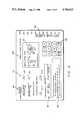
- FIG. 6an example of a display/ input device for the microprocessor and display unit 118 for the device of FIG. 5 is illustrated generally at 68.
- the display/input device 68allows the individual exerciser to enter in the maximum amount of weight, which is equivalent to the amount of resistance desired to be applied by the resistance mechanism 116, for a selected exercise of the device 100.
- the exercise device as schematically illustrated on the display/input device 68is of the device 100 discussed above for exercising the two different portions of the thigh muscle group. As stated, the inner/outer thigh muscle group may be exercised concurrently or subsequently.
- the display/input device 68includes an exercise illustration portion 70 wherein the user's legs in the illustration labeled A move the two pivotalarms 108 and 110 apart to exercise the outer thigh muscles.
- the schematic leg illustration labeled Bshows exercising the inner thigh muscle group by moving the arms 108 and 110 inward.
- the display/input device 68also indicates the maximum weight selection for each of the motions labeled A and B at the two locations indicated generally at 74.
- the illustrateddisplay/input device 68allows an individual to either first work the innerthigh muscles and then subsequently the outer thigh muscles, or to work both groups concurrently.
- the entering of the particular maximum weight or resistance equivalentsis done through the keyboard 72 and displayed at that portion 74 of the display/input 68. If the exerciser desires to work both the inner and outer thigh, a maximum weight is selected for each positive resistance direction.
- the display/input device 68further shows both the average for the range of motion for the total repetitions and the overall performance for the particular exercise at location 76, and a performance improvement instruction area as indicated at location 78. Finally, a bar graph 80 indicates the range of motion for each repetition.
- the first step in operating the exercise device of the inventionis to activate the device and thus supply pcwer to the microprocessor and keyboard unit llB, which is done by pushing the start button 82 on display/input 68.
- step twoinvclves the individual exerciser entering via the keyboard 72 the maximum desired weight for either one of the particular exercises "A” or “B", or both, which weight is equivalent to the amount of resistance which will be applied to movement of the particular arms 108 and 110 of the device 100.
- the third stepinvolves the actual moving of the arms 108 and 110 through the particular range of motion by the exerciser.
- the amount of resistance applied as the arms 108 and 110 are moved in the first or second positive resistance directionwill vary in accordance with two different force gradients, one such gradient for the inner thigh exercise movement and onefor the outer thigh movement, as programmed into the processor of the microprocessor and display unit 118.
- the exerciser's movement through the range of movement for each repetitionis shown by bar graph 80.
- the unit 110functions to reduce the applied resistance to substantially zero.
- the fourth steprequires the exerciser to repeat the particular exercise bymoving the arms 108 and 110 through the range of motion in the given directions.
- the fifth stepinvolves the averaging of the total repetitious movements ofthe arms 108 and 110 by the exerciser through the range of motion by a suitable provided programming of the unit 118 to allow for a determinationof a performance rating, which is displayed to the exerciser at location 76.
- step 6the individual may reactivate this particular machine and carry out steps 1-5 again or move on to another exercise machine and repeat similar procedures on that machine.
Landscapes
- Health & Medical Sciences (AREA)
- Life Sciences & Earth Sciences (AREA)
- Biophysics (AREA)
- Orthopedic Medicine & Surgery (AREA)
- General Health & Medical Sciences (AREA)
- Physical Education & Sports Medicine (AREA)
- Physics & Mathematics (AREA)
- Electromagnetism (AREA)
- Rehabilitation Tools (AREA)
Abstract
Description
Performance Rating=a×b×10
Claims (17)
Priority Applications (1)
| Application Number | Priority Date | Filing Date | Title |
|---|---|---|---|
| US07/006,049US4765613A (en) | 1987-01-22 | 1987-01-22 | Progressive resistance exercise device |
Applications Claiming Priority (1)
| Application Number | Priority Date | Filing Date | Title |
|---|---|---|---|
| US07/006,049US4765613A (en) | 1987-01-22 | 1987-01-22 | Progressive resistance exercise device |
Publications (1)
| Publication Number | Publication Date |
|---|---|
| US4765613Atrue US4765613A (en) | 1988-08-23 |
Family
ID=21719037
Family Applications (1)
| Application Number | Title | Priority Date | Filing Date |
|---|---|---|---|
| US07/006,049Expired - Fee RelatedUS4765613A (en) | 1987-01-22 | 1987-01-22 | Progressive resistance exercise device |
Country Status (1)
| Country | Link |
|---|---|
| US (1) | US4765613A (en) |
Cited By (85)
| Publication number | Priority date | Publication date | Assignee | Title |
|---|---|---|---|---|
| US4949959A (en)* | 1989-10-10 | 1990-08-21 | Stevens William E | Barbell assist device |
| WO1991007214A1 (en)* | 1989-11-13 | 1991-05-30 | Walker Fitness Systems, Inc. | Automatic force generating and control system |
| US5054774A (en)* | 1990-06-12 | 1991-10-08 | Chattecx | Computer-controlled muscle exercising machine having simplified data access |
| US5058888A (en)* | 1989-11-13 | 1991-10-22 | Walker Fitness Systems, Inc. | Automatic force generating and control system |
| US5080351A (en)* | 1989-09-06 | 1992-01-14 | Diversified Products Corporation | Compact multi-function weight-training exerciser |
| USD325610S (en) | 1989-11-13 | 1992-04-21 | Walker Fitness Systems, Inc. | Physical exerciser |
| US5151071A (en)* | 1990-10-05 | 1992-09-29 | Baltimore Therapeutic Equipment Co. | Isoinertial lifting device |
| US5195937A (en)* | 1990-03-28 | 1993-03-23 | Nordictrack, Inc. | Multi-exercise apparatus |
| US5209715A (en)* | 1989-11-13 | 1993-05-11 | Walker Fitness Systems, Inc. | Automatic force generating and control system |
| US5260870A (en)* | 1989-11-22 | 1993-11-09 | Combi Corporation | Apparatus for measuring instantaneous power by leg-stretching power |
| US5302161A (en)* | 1990-03-28 | 1994-04-12 | Noordictrack, Inc. | Flexible line guidance and tension measuring device |
| US5431609A (en)* | 1991-07-11 | 1995-07-11 | Panagiotopoulos; Anastasios | Electrical resistance exercise device with lift assistance |
| US5435798A (en)* | 1993-08-17 | 1995-07-25 | Pacific Fitness Corporation | Exercise apparatus with electronically variable resistance |
| US5655997A (en)* | 1994-07-07 | 1997-08-12 | Integrated Fitness Corporation | Fitness feedback system for weight stack machines |
| US5695431A (en)* | 1991-11-08 | 1997-12-09 | Cedaron Medical, Inc. | Physiological evaluation and exercise system |
| US5697869A (en)* | 1993-06-02 | 1997-12-16 | Ehrenfried Technologies, Inc. | Electromechanical resistance exercise apparatus |
| US5738611A (en)* | 1993-06-02 | 1998-04-14 | The Ehrenfried Company | Aerobic and strength exercise apparatus |
| US5788605A (en)* | 1997-04-04 | 1998-08-04 | Kuo; Hai Pin | Resistance mechanism for an exercising device |
| US5788616A (en)* | 1997-08-04 | 1998-08-04 | Polidi; Richard | Mechanical weightlifting machine |
| AU724480B2 (en)* | 1997-04-01 | 2000-09-21 | Hai Pin Kuo | A resistance mechanism for an exercising device |
| US6379287B1 (en) | 1998-11-30 | 2002-04-30 | Prospot, Inc. | Barbell and dumbbell safety spotting apparatus |
| US6468188B1 (en)* | 2000-03-30 | 2002-10-22 | Jam'n Fitness Corp. | Exercise apparatus for gluteus and hamstring muscles |
| US20030171195A1 (en)* | 2002-03-04 | 2003-09-11 | Raymond Giannelli | Arm extension machine |
| US6626805B1 (en)* | 1990-03-09 | 2003-09-30 | William S. Lightbody | Exercise machine |
| US20040162194A1 (en)* | 2003-02-14 | 2004-08-19 | Habing Douglas J. | Exercise machine with adjustable range of motion |
| US20040162195A1 (en)* | 2003-02-14 | 2004-08-19 | Habing Douglas J. | Single apparatus converging/diverging exercise machine |
| WO2005013821A1 (en)* | 2003-08-07 | 2005-02-17 | Tek Solutions Pty Ltd | Method and apparatus for physiological testing |
| AU2004262441B2 (en)* | 2003-08-07 | 2005-11-10 | Tek Solutions Pty Ltd | Method and apparatus for physiological testing |
| US20060094570A1 (en)* | 2001-05-24 | 2006-05-04 | Schneider Kenneth G | Complete body fitness machine |
| US20060135325A1 (en)* | 2004-08-13 | 2006-06-22 | Holness Wilfred W | Apparatus for isometric and incremental muscle contractions |
| US7070545B2 (en) | 2002-07-01 | 2006-07-04 | Nautilus, Inc. | Leg press and abdominal crunch exercise machine |
| US7070546B1 (en) | 2002-07-05 | 2006-07-04 | Joseph Grasso | Exercise apparatus including multiple function aspects and small footprint |
| US7083554B1 (en) | 1997-02-27 | 2006-08-01 | Nautilus, Inc. | Exercise machine with infinite position range limiter and automatic belt tensioning system |
| US20060205566A1 (en)* | 1999-07-08 | 2006-09-14 | Watterson Scott R | Systems for interaction with exercise device |
| US7108641B2 (en) | 2000-05-03 | 2006-09-19 | Nautilus, Inc. | Exercise equipment with multi-positioning handles |
| US7115080B2 (en) | 2002-08-01 | 2006-10-03 | Nautilus, Inc. | Collapsible seat for combination hack squat and leg press machine |
| US20060281603A1 (en)* | 1995-12-14 | 2006-12-14 | Hickman Paul L | Method and apparatus for remote interactive exercise and health equipment |
| DE102005041582A1 (en)* | 2005-09-01 | 2007-03-08 | Hany Bayadssi | Fitness apparatus has grip rod moved by user from start to end position, who has to overcome load working on rod while doing so where loading provides force depending on rod's movement |
| US7189190B2 (en) | 2000-03-10 | 2007-03-13 | Nautilus, Inc. | Group program for resistance exercise training |
| US20070184952A1 (en)* | 2006-02-09 | 2007-08-09 | Konami Sports & Life Co., Ltd. | Training apparatus |
| US20070254787A1 (en)* | 2006-04-27 | 2007-11-01 | Konami Sports & Life Co., Ltd. | Training apparatus |
| US20070265138A1 (en)* | 1999-07-08 | 2007-11-15 | Ashby Darren C | Methods and systems for controlling an exercise apparatus using a portable data storage device |
| US20080248926A1 (en)* | 2006-11-27 | 2008-10-09 | Cole Neil M | Training System and Method |
| US7537546B2 (en) | 1999-07-08 | 2009-05-26 | Icon Ip, Inc. | Systems and methods for controlling the operation of one or more exercise devices and providing motivational programming |
| US20090149780A1 (en)* | 2003-08-07 | 2009-06-11 | Richard Creswick | Method and Apparatus for Physiological Testing |
| US7549947B2 (en) | 2001-10-19 | 2009-06-23 | Icon Ip, Inc. | Mobile systems and methods for health, exercise and competition |
| US7556590B2 (en) | 1999-07-08 | 2009-07-07 | Icon Ip, Inc. | Systems and methods for enabling two-way communication between one or more exercise devices and computer devices and for enabling users of the one or more exercise devices to competitively exercise |
| US7628730B1 (en) | 1999-07-08 | 2009-12-08 | Icon Ip, Inc. | Methods and systems for controlling an exercise apparatus using a USB compatible portable remote device |
| US7771319B1 (en)* | 2004-05-10 | 2010-08-10 | Michael G. Lannon | Exercising apparatus |
| US7841970B2 (en) | 2006-07-28 | 2010-11-30 | Michael Striar | Variable weight device |
| US7922635B2 (en) | 2000-03-10 | 2011-04-12 | Nautilus, Inc. | Adjustable-load unitary multi-position bench exercise unit |
| US20110092343A1 (en)* | 2003-02-14 | 2011-04-21 | Habing Douglas J | Single Apparatus Converging/Diverging Exercise Machine |
| WO2011083434A1 (en)* | 2010-01-07 | 2011-07-14 | Camerota, Vittore | Machine for the power exercise of a user |
| US8029415B2 (en) | 1999-07-08 | 2011-10-04 | Icon Ip, Inc. | Systems, methods, and devices for simulating real world terrain on an exercise device |
| US20110245039A1 (en)* | 2000-10-06 | 2011-10-06 | Stearns Kenneth W | Total body exercise methods and apparatus |
| AU2009251094B2 (en)* | 2003-08-07 | 2012-07-12 | Tek Solutions Pty Ltd | Method and apparatus for physiological testing |
| US8251874B2 (en) | 2009-03-27 | 2012-08-28 | Icon Health & Fitness, Inc. | Exercise systems for simulating real world terrain |
| KR101220432B1 (en) | 2011-06-14 | 2013-01-10 | 구경순 | Exercise equipment |
| US20140014604A1 (en)* | 2012-07-10 | 2014-01-16 | Marcula Equipamentos De Musculacao Ltda. | Urban sports furniture |
| US8968155B2 (en) | 2012-07-31 | 2015-03-03 | John M. Bird | Resistance apparatus, system, and method |
| US20150141199A1 (en)* | 2004-05-10 | 2015-05-21 | Michael G. Lannon | Exercising Apparatus |
| RU2574981C2 (en)* | 2010-01-07 | 2016-02-10 | КАМЕРОТА Витторе | Simulator for performing power physical exercises by user |
| US9472999B1 (en)* | 2015-03-25 | 2016-10-18 | Chi Hua Fitness Co., Ltd. | Damper with linear power generation and reluctance |
| US9636540B2 (en) | 2015-03-10 | 2017-05-02 | True Fitness Technology, Inc. | Adjustable stride elliptical motion exercise machine with large stride variability and fast adjustment |
| US10188890B2 (en) | 2013-12-26 | 2019-01-29 | Icon Health & Fitness, Inc. | Magnetic resistance mechanism in a cable machine |
| US10220259B2 (en) | 2012-01-05 | 2019-03-05 | Icon Health & Fitness, Inc. | System and method for controlling an exercise device |
| US10226396B2 (en) | 2014-06-20 | 2019-03-12 | Icon Health & Fitness, Inc. | Post workout massage device |
| US10252109B2 (en) | 2016-05-13 | 2019-04-09 | Icon Health & Fitness, Inc. | Weight platform treadmill |
| US10272317B2 (en) | 2016-03-18 | 2019-04-30 | Icon Health & Fitness, Inc. | Lighted pace feature in a treadmill |
| US10279212B2 (en) | 2013-03-14 | 2019-05-07 | Icon Health & Fitness, Inc. | Strength training apparatus with flywheel and related methods |
| US10293211B2 (en) | 2016-03-18 | 2019-05-21 | Icon Health & Fitness, Inc. | Coordinated weight selection |
| US10391361B2 (en) | 2015-02-27 | 2019-08-27 | Icon Health & Fitness, Inc. | Simulating real-world terrain on an exercise device |
| US10426989B2 (en) | 2014-06-09 | 2019-10-01 | Icon Health & Fitness, Inc. | Cable system incorporated into a treadmill |
| US10433612B2 (en) | 2014-03-10 | 2019-10-08 | Icon Health & Fitness, Inc. | Pressure sensor to quantify work |
| US10441840B2 (en) | 2016-03-18 | 2019-10-15 | Icon Health & Fitness, Inc. | Collapsible strength exercise machine |
| US10449416B2 (en) | 2015-08-26 | 2019-10-22 | Icon Health & Fitness, Inc. | Strength exercise mechanisms |
| US10493349B2 (en) | 2016-03-18 | 2019-12-03 | Icon Health & Fitness, Inc. | Display on exercise device |
| US10625137B2 (en) | 2016-03-18 | 2020-04-21 | Icon Health & Fitness, Inc. | Coordinated displays in an exercise device |
| US10661114B2 (en) | 2016-11-01 | 2020-05-26 | Icon Health & Fitness, Inc. | Body weight lift mechanism on treadmill |
| US10671705B2 (en) | 2016-09-28 | 2020-06-02 | Icon Health & Fitness, Inc. | Customizing recipe recommendations |
| US10814172B1 (en)* | 2018-03-29 | 2020-10-27 | Quickhit International, Inc. | Exercise equipment and systems |
| US10940360B2 (en) | 2015-08-26 | 2021-03-09 | Icon Health & Fitness, Inc. | Strength exercise mechanisms |
| US11406858B2 (en)* | 2018-12-17 | 2022-08-09 | Vr Optics, Llc | Systems and methods for providing varying resistance in exercise equipment through loop drive mechanism |
| US12239871B1 (en) | 2018-03-29 | 2025-03-04 | Quickhit International, Inc. | Exercise equipment and systems |
| US12318651B2 (en) | 2022-12-28 | 2025-06-03 | Matthew Burkhardt | Resistance exercise device |
Citations (10)
| Publication number | Priority date | Publication date | Assignee | Title |
|---|---|---|---|---|
| US3395698A (en)* | 1965-10-01 | 1968-08-06 | Mc Donnell Douglas Corp | Physiologically paced ergomeric system |
| US3767195A (en)* | 1969-03-03 | 1973-10-23 | Lifecycle Inc | Programmed bicycle exerciser |
| US3869121A (en)* | 1972-07-10 | 1975-03-04 | Evan R Flavell | Proportioned resistance exercise servo system |
| US4235437A (en)* | 1978-07-03 | 1980-11-25 | Book Wayne J | Robotic exercise machine and method |
| US4261562A (en)* | 1978-12-22 | 1981-04-14 | Flavell Evan R | Electromagnetically regulated exerciser |
| US4354676A (en)* | 1978-10-13 | 1982-10-19 | Pepsico, Inc. | Exerciser |
| US4518163A (en)* | 1980-10-20 | 1985-05-21 | Arthur C. Bentley | Exerciser with electrically controlled resistance |
| US4544154A (en)* | 1978-10-13 | 1985-10-01 | Pepsico, Inc. | Passive programmable resistance device |
| US4569518A (en)* | 1983-02-16 | 1986-02-11 | Fulks Kent B | Programmable exercise system |
| US4620703A (en)* | 1984-10-12 | 1986-11-04 | Greenhut Paul M | Exercise apparatus |
- 1987
- 1987-01-22USUS07/006,049patent/US4765613A/ennot_activeExpired - Fee Related
Patent Citations (10)
| Publication number | Priority date | Publication date | Assignee | Title |
|---|---|---|---|---|
| US3395698A (en)* | 1965-10-01 | 1968-08-06 | Mc Donnell Douglas Corp | Physiologically paced ergomeric system |
| US3767195A (en)* | 1969-03-03 | 1973-10-23 | Lifecycle Inc | Programmed bicycle exerciser |
| US3869121A (en)* | 1972-07-10 | 1975-03-04 | Evan R Flavell | Proportioned resistance exercise servo system |
| US4235437A (en)* | 1978-07-03 | 1980-11-25 | Book Wayne J | Robotic exercise machine and method |
| US4354676A (en)* | 1978-10-13 | 1982-10-19 | Pepsico, Inc. | Exerciser |
| US4544154A (en)* | 1978-10-13 | 1985-10-01 | Pepsico, Inc. | Passive programmable resistance device |
| US4261562A (en)* | 1978-12-22 | 1981-04-14 | Flavell Evan R | Electromagnetically regulated exerciser |
| US4518163A (en)* | 1980-10-20 | 1985-05-21 | Arthur C. Bentley | Exerciser with electrically controlled resistance |
| US4569518A (en)* | 1983-02-16 | 1986-02-11 | Fulks Kent B | Programmable exercise system |
| US4620703A (en)* | 1984-10-12 | 1986-11-04 | Greenhut Paul M | Exercise apparatus |
Cited By (138)
| Publication number | Priority date | Publication date | Assignee | Title |
|---|---|---|---|---|
| US5080351A (en)* | 1989-09-06 | 1992-01-14 | Diversified Products Corporation | Compact multi-function weight-training exerciser |
| US4949959A (en)* | 1989-10-10 | 1990-08-21 | Stevens William E | Barbell assist device |
| US5058888A (en)* | 1989-11-13 | 1991-10-22 | Walker Fitness Systems, Inc. | Automatic force generating and control system |
| WO1991007214A1 (en)* | 1989-11-13 | 1991-05-30 | Walker Fitness Systems, Inc. | Automatic force generating and control system |
| USD325610S (en) | 1989-11-13 | 1992-04-21 | Walker Fitness Systems, Inc. | Physical exerciser |
| US5209715A (en)* | 1989-11-13 | 1993-05-11 | Walker Fitness Systems, Inc. | Automatic force generating and control system |
| US5260870A (en)* | 1989-11-22 | 1993-11-09 | Combi Corporation | Apparatus for measuring instantaneous power by leg-stretching power |
| US20040063551A1 (en)* | 1990-03-09 | 2004-04-01 | Lightbody William S. | Exercise machine |
| US6626805B1 (en)* | 1990-03-09 | 2003-09-30 | William S. Lightbody | Exercise machine |
| US5195937A (en)* | 1990-03-28 | 1993-03-23 | Nordictrack, Inc. | Multi-exercise apparatus |
| US5302161A (en)* | 1990-03-28 | 1994-04-12 | Noordictrack, Inc. | Flexible line guidance and tension measuring device |
| US5054774A (en)* | 1990-06-12 | 1991-10-08 | Chattecx | Computer-controlled muscle exercising machine having simplified data access |
| US5151071A (en)* | 1990-10-05 | 1992-09-29 | Baltimore Therapeutic Equipment Co. | Isoinertial lifting device |
| US5431609A (en)* | 1991-07-11 | 1995-07-11 | Panagiotopoulos; Anastasios | Electrical resistance exercise device with lift assistance |
| US5695431A (en)* | 1991-11-08 | 1997-12-09 | Cedaron Medical, Inc. | Physiological evaluation and exercise system |
| US6050920A (en)* | 1993-06-02 | 2000-04-18 | Ehrenfried Technologies, Inc. | Electromechanical resistance exercise apparatus |
| US5697869A (en)* | 1993-06-02 | 1997-12-16 | Ehrenfried Technologies, Inc. | Electromechanical resistance exercise apparatus |
| US5738611A (en)* | 1993-06-02 | 1998-04-14 | The Ehrenfried Company | Aerobic and strength exercise apparatus |
| US5435798A (en)* | 1993-08-17 | 1995-07-25 | Pacific Fitness Corporation | Exercise apparatus with electronically variable resistance |
| US5785632A (en)* | 1994-07-07 | 1998-07-28 | Integrated Fitness Corporation | Fitness feedback system for weight stack machines |
| US5655997A (en)* | 1994-07-07 | 1997-08-12 | Integrated Fitness Corporation | Fitness feedback system for weight stack machines |
| US7510509B2 (en) | 1995-12-14 | 2009-03-31 | Icon Ip, Inc. | Method and apparatus for remote interactive exercise and health equipment |
| US7575536B1 (en)* | 1995-12-14 | 2009-08-18 | Icon Ip, Inc. | Method and apparatus for remote interactive exercise and health equipment |
| US7625315B2 (en) | 1995-12-14 | 2009-12-01 | Icon Ip, Inc. | Exercise and health equipment |
| US7980996B2 (en) | 1995-12-14 | 2011-07-19 | Icon Ip, Inc. | Method and apparatus for remote interactive exercise and health equipment |
| US8298123B2 (en) | 1995-12-14 | 2012-10-30 | Icon Health & Fitness, Inc. | Method and apparatus for remote interactive exercise and health equipment |
| US20060281603A1 (en)* | 1995-12-14 | 2006-12-14 | Hickman Paul L | Method and apparatus for remote interactive exercise and health equipment |
| US7637847B1 (en) | 1995-12-14 | 2009-12-29 | Icon Ip, Inc. | Exercise system and method with virtual personal trainer forewarning |
| US7713171B1 (en) | 1995-12-14 | 2010-05-11 | Icon Ip, Inc. | Exercise equipment with removable digital script memory |
| US7083554B1 (en) | 1997-02-27 | 2006-08-01 | Nautilus, Inc. | Exercise machine with infinite position range limiter and automatic belt tensioning system |
| AU724480B2 (en)* | 1997-04-01 | 2000-09-21 | Hai Pin Kuo | A resistance mechanism for an exercising device |
| US5788605A (en)* | 1997-04-04 | 1998-08-04 | Kuo; Hai Pin | Resistance mechanism for an exercising device |
| US5788616A (en)* | 1997-08-04 | 1998-08-04 | Polidi; Richard | Mechanical weightlifting machine |
| US6379287B1 (en) | 1998-11-30 | 2002-04-30 | Prospot, Inc. | Barbell and dumbbell safety spotting apparatus |
| US7862478B2 (en) | 1999-07-08 | 2011-01-04 | Icon Ip, Inc. | System and methods for controlling the operation of one or more exercise devices and providing motivational programming |
| US8758201B2 (en) | 1999-07-08 | 2014-06-24 | Icon Health & Fitness, Inc. | Portable physical activity sensing system |
| US7556590B2 (en) | 1999-07-08 | 2009-07-07 | Icon Ip, Inc. | Systems and methods for enabling two-way communication between one or more exercise devices and computer devices and for enabling users of the one or more exercise devices to competitively exercise |
| US20060205566A1 (en)* | 1999-07-08 | 2006-09-14 | Watterson Scott R | Systems for interaction with exercise device |
| US7645213B2 (en) | 1999-07-08 | 2010-01-12 | Watterson Scott R | Systems for interaction with exercise device |
| US9028368B2 (en) | 1999-07-08 | 2015-05-12 | Icon Health & Fitness, Inc. | Systems, methods, and devices for simulating real world terrain on an exercise device |
| US8029415B2 (en) | 1999-07-08 | 2011-10-04 | Icon Ip, Inc. | Systems, methods, and devices for simulating real world terrain on an exercise device |
| US8784270B2 (en) | 1999-07-08 | 2014-07-22 | Icon Ip, Inc. | Portable physical activity sensing system |
| US7537546B2 (en) | 1999-07-08 | 2009-05-26 | Icon Ip, Inc. | Systems and methods for controlling the operation of one or more exercise devices and providing motivational programming |
| US7789800B1 (en) | 1999-07-08 | 2010-09-07 | Icon Ip, Inc. | Methods and systems for controlling an exercise apparatus using a USB compatible portable remote device |
| US7981000B2 (en) | 1999-07-08 | 2011-07-19 | Icon Ip, Inc. | Systems for interaction with exercise device |
| US8690735B2 (en) | 1999-07-08 | 2014-04-08 | Icon Health & Fitness, Inc. | Systems for interaction with exercise device |
| US20070265138A1 (en)* | 1999-07-08 | 2007-11-15 | Ashby Darren C | Methods and systems for controlling an exercise apparatus using a portable data storage device |
| US7985164B2 (en) | 1999-07-08 | 2011-07-26 | Icon Ip, Inc. | Methods and systems for controlling an exercise apparatus using a portable data storage device |
| US7455622B2 (en) | 1999-07-08 | 2008-11-25 | Icon Ip, Inc. | Systems for interaction with exercise device |
| US7628730B1 (en) | 1999-07-08 | 2009-12-08 | Icon Ip, Inc. | Methods and systems for controlling an exercise apparatus using a USB compatible portable remote device |
| US20070207447A1 (en)* | 2000-03-10 | 2007-09-06 | Nautilus, Inc. | Group program for resistance exercise training |
| US7189190B2 (en) | 2000-03-10 | 2007-03-13 | Nautilus, Inc. | Group program for resistance exercise training |
| US7922635B2 (en) | 2000-03-10 | 2011-04-12 | Nautilus, Inc. | Adjustable-load unitary multi-position bench exercise unit |
| US6468188B1 (en)* | 2000-03-30 | 2002-10-22 | Jam'n Fitness Corp. | Exercise apparatus for gluteus and hamstring muscles |
| US7108641B2 (en) | 2000-05-03 | 2006-09-19 | Nautilus, Inc. | Exercise equipment with multi-positioning handles |
| US7608028B2 (en) | 2000-05-03 | 2009-10-27 | Nautilus, Inc. | Exercise equipment with multi-positioning handles |
| US20110245039A1 (en)* | 2000-10-06 | 2011-10-06 | Stearns Kenneth W | Total body exercise methods and apparatus |
| US8292787B2 (en)* | 2000-10-06 | 2012-10-23 | Kenneth W Stearns | Total body exercise methods and apparatus |
| US20060094570A1 (en)* | 2001-05-24 | 2006-05-04 | Schneider Kenneth G | Complete body fitness machine |
| US7699754B2 (en)* | 2001-05-24 | 2010-04-20 | Kenneth George Schneider | Complete body fitness machine |
| US7857731B2 (en) | 2001-10-19 | 2010-12-28 | Icon Ip, Inc. | Mobile systems and methods for health, exercise and competition |
| US7549947B2 (en) | 2001-10-19 | 2009-06-23 | Icon Ip, Inc. | Mobile systems and methods for health, exercise and competition |
| US20030171195A1 (en)* | 2002-03-04 | 2003-09-11 | Raymond Giannelli | Arm extension machine |
| US7608022B2 (en) | 2002-07-01 | 2009-10-27 | Nautilus, Inc. | Leg press and abdominal crunch exercise machine |
| US7070545B2 (en) | 2002-07-01 | 2006-07-04 | Nautilus, Inc. | Leg press and abdominal crunch exercise machine |
| US7070546B1 (en) | 2002-07-05 | 2006-07-04 | Joseph Grasso | Exercise apparatus including multiple function aspects and small footprint |
| US7115080B2 (en) | 2002-08-01 | 2006-10-03 | Nautilus, Inc. | Collapsible seat for combination hack squat and leg press machine |
| US7811211B2 (en) | 2003-02-14 | 2010-10-12 | Habing Douglas J | Single apparatus converging/diverging exercise machine |
| US20110092343A1 (en)* | 2003-02-14 | 2011-04-21 | Habing Douglas J | Single Apparatus Converging/Diverging Exercise Machine |
| US20040162195A1 (en)* | 2003-02-14 | 2004-08-19 | Habing Douglas J. | Single apparatus converging/diverging exercise machine |
| US20040162194A1 (en)* | 2003-02-14 | 2004-08-19 | Habing Douglas J. | Exercise machine with adjustable range of motion |
| AU2009251094B2 (en)* | 2003-08-07 | 2012-07-12 | Tek Solutions Pty Ltd | Method and apparatus for physiological testing |
| US20060173384A1 (en)* | 2003-08-07 | 2006-08-03 | Tek Solutions Pty Ltd | Method and apparatus for physiological testing |
| AU2004262441B2 (en)* | 2003-08-07 | 2005-11-10 | Tek Solutions Pty Ltd | Method and apparatus for physiological testing |
| WO2005013821A1 (en)* | 2003-08-07 | 2005-02-17 | Tek Solutions Pty Ltd | Method and apparatus for physiological testing |
| US7488299B2 (en) | 2003-08-07 | 2009-02-10 | Tek Solutions Pty Ltd | Method and apparatus for physiological testing |
| US7955277B2 (en) | 2003-08-07 | 2011-06-07 | Tek Solutions Pty Ltd | Method and apparatus for physiological testing |
| US20090149780A1 (en)* | 2003-08-07 | 2009-06-11 | Richard Creswick | Method and Apparatus for Physiological Testing |
| US7794359B1 (en) | 2004-05-10 | 2010-09-14 | Michael G. Lannon | Process and apparatus for exercising an operator |
| US8747282B2 (en) | 2004-05-10 | 2014-06-10 | Michael G. Lannon | Process and apparatus for exercising an operator |
| US9233269B2 (en)* | 2004-05-10 | 2016-01-12 | Michael G. Lannon | Exercising apparatus |
| US20150141199A1 (en)* | 2004-05-10 | 2015-05-21 | Michael G. Lannon | Exercising Apparatus |
| US9480878B2 (en) | 2004-05-10 | 2016-11-01 | Michael G. Lannon | Exercising apparatus |
| US20100292052A1 (en)* | 2004-05-10 | 2010-11-18 | Spoeth Jr Carl R | Exercising Apparatus |
| US8585556B2 (en)* | 2004-05-10 | 2013-11-19 | Michael G. Lannon | Exercising apparatus |
| US20100261580A1 (en)* | 2004-05-10 | 2010-10-14 | Lannon Michael G | Process And Apparatus For Exercising An Operator |
| US8105209B2 (en) | 2004-05-10 | 2012-01-31 | Michael G. Lannon | Process and apparatus for exercising an operator |
| US8197389B2 (en)* | 2004-05-10 | 2012-06-12 | Michael G. Lannon | Exercising apparatus |
| US9884224B2 (en) | 2004-05-10 | 2018-02-06 | Michael G. Lannon | Exercising apparatus |
| US7771319B1 (en)* | 2004-05-10 | 2010-08-10 | Michael G. Lannon | Exercising apparatus |
| US9278254B2 (en)* | 2004-08-13 | 2016-03-08 | Wilfred Washington Holness | Apparatus for isometric and incremental muscle contractions |
| US9943720B2 (en)* | 2004-08-13 | 2018-04-17 | Wilfred Holness | Apparatus for isometric and incremental muscle contractions |
| US20060135325A1 (en)* | 2004-08-13 | 2006-06-22 | Holness Wilfred W | Apparatus for isometric and incremental muscle contractions |
| US20160296786A1 (en)* | 2004-08-13 | 2016-10-13 | Wilfred Holness | Apparatus for isometric and incremental muscle contractions |
| DE102005041582A1 (en)* | 2005-09-01 | 2007-03-08 | Hany Bayadssi | Fitness apparatus has grip rod moved by user from start to end position, who has to overcome load working on rod while doing so where loading provides force depending on rod's movement |
| DE102005041582B4 (en)* | 2005-09-01 | 2011-01-20 | Hany Bayadssi | fitness device |
| US20070184952A1 (en)* | 2006-02-09 | 2007-08-09 | Konami Sports & Life Co., Ltd. | Training apparatus |
| US20070254787A1 (en)* | 2006-04-27 | 2007-11-01 | Konami Sports & Life Co., Ltd. | Training apparatus |
| US7841970B2 (en) | 2006-07-28 | 2010-11-30 | Michael Striar | Variable weight device |
| US20100279821A1 (en)* | 2006-11-27 | 2010-11-04 | Cole Neil M | Training System and Method |
| US7785232B2 (en)* | 2006-11-27 | 2010-08-31 | Cole Neil M | Training system and method |
| US7854685B2 (en) | 2006-11-27 | 2010-12-21 | Cole Neil M | Training system and method |
| US20080248926A1 (en)* | 2006-11-27 | 2008-10-09 | Cole Neil M | Training System and Method |
| US8251874B2 (en) | 2009-03-27 | 2012-08-28 | Icon Health & Fitness, Inc. | Exercise systems for simulating real world terrain |
| US20130065730A1 (en)* | 2010-01-07 | 2013-03-14 | Antonio Camerota | Machine for the power exercise of a user |
| RU2574981C2 (en)* | 2010-01-07 | 2016-02-10 | КАМЕРОТА Витторе | Simulator for performing power physical exercises by user |
| WO2011083434A1 (en)* | 2010-01-07 | 2011-07-14 | Camerota, Vittore | Machine for the power exercise of a user |
| KR101220432B1 (en) | 2011-06-14 | 2013-01-10 | 구경순 | Exercise equipment |
| US10220259B2 (en) | 2012-01-05 | 2019-03-05 | Icon Health & Fitness, Inc. | System and method for controlling an exercise device |
| US20140014604A1 (en)* | 2012-07-10 | 2014-01-16 | Marcula Equipamentos De Musculacao Ltda. | Urban sports furniture |
| US8968155B2 (en) | 2012-07-31 | 2015-03-03 | John M. Bird | Resistance apparatus, system, and method |
| US11071890B2 (en) | 2012-07-31 | 2021-07-27 | John M. Bird | Resistance apparatus, system, and method |
| US9717952B2 (en) | 2012-07-31 | 2017-08-01 | John M. Bird | Resistance apparatus, system, and method |
| US10159869B2 (en) | 2012-07-31 | 2018-12-25 | John M. Bird | Resistance apparatus, system and method |
| US10159870B2 (en) | 2012-07-31 | 2018-12-25 | John M. Bird | Resistance apparatus, system, and method |
| US11833394B2 (en) | 2012-07-31 | 2023-12-05 | John M. Bird | Exercise apparatus with motor induced resistance |
| US10279212B2 (en) | 2013-03-14 | 2019-05-07 | Icon Health & Fitness, Inc. | Strength training apparatus with flywheel and related methods |
| US10188890B2 (en) | 2013-12-26 | 2019-01-29 | Icon Health & Fitness, Inc. | Magnetic resistance mechanism in a cable machine |
| US10433612B2 (en) | 2014-03-10 | 2019-10-08 | Icon Health & Fitness, Inc. | Pressure sensor to quantify work |
| US10426989B2 (en) | 2014-06-09 | 2019-10-01 | Icon Health & Fitness, Inc. | Cable system incorporated into a treadmill |
| US10226396B2 (en) | 2014-06-20 | 2019-03-12 | Icon Health & Fitness, Inc. | Post workout massage device |
| US10391361B2 (en) | 2015-02-27 | 2019-08-27 | Icon Health & Fitness, Inc. | Simulating real-world terrain on an exercise device |
| US9636540B2 (en) | 2015-03-10 | 2017-05-02 | True Fitness Technology, Inc. | Adjustable stride elliptical motion exercise machine with large stride variability and fast adjustment |
| US9472999B1 (en)* | 2015-03-25 | 2016-10-18 | Chi Hua Fitness Co., Ltd. | Damper with linear power generation and reluctance |
| US10449416B2 (en) | 2015-08-26 | 2019-10-22 | Icon Health & Fitness, Inc. | Strength exercise mechanisms |
| US10940360B2 (en) | 2015-08-26 | 2021-03-09 | Icon Health & Fitness, Inc. | Strength exercise mechanisms |
| US10293211B2 (en) | 2016-03-18 | 2019-05-21 | Icon Health & Fitness, Inc. | Coordinated weight selection |
| US10493349B2 (en) | 2016-03-18 | 2019-12-03 | Icon Health & Fitness, Inc. | Display on exercise device |
| US10625137B2 (en) | 2016-03-18 | 2020-04-21 | Icon Health & Fitness, Inc. | Coordinated displays in an exercise device |
| US10441840B2 (en) | 2016-03-18 | 2019-10-15 | Icon Health & Fitness, Inc. | Collapsible strength exercise machine |
| US10272317B2 (en) | 2016-03-18 | 2019-04-30 | Icon Health & Fitness, Inc. | Lighted pace feature in a treadmill |
| US10252109B2 (en) | 2016-05-13 | 2019-04-09 | Icon Health & Fitness, Inc. | Weight platform treadmill |
| US10671705B2 (en) | 2016-09-28 | 2020-06-02 | Icon Health & Fitness, Inc. | Customizing recipe recommendations |
| US10661114B2 (en) | 2016-11-01 | 2020-05-26 | Icon Health & Fitness, Inc. | Body weight lift mechanism on treadmill |
| US10814172B1 (en)* | 2018-03-29 | 2020-10-27 | Quickhit International, Inc. | Exercise equipment and systems |
| US12239871B1 (en) | 2018-03-29 | 2025-03-04 | Quickhit International, Inc. | Exercise equipment and systems |
| US11406858B2 (en)* | 2018-12-17 | 2022-08-09 | Vr Optics, Llc | Systems and methods for providing varying resistance in exercise equipment through loop drive mechanism |
| US12318651B2 (en) | 2022-12-28 | 2025-06-03 | Matthew Burkhardt | Resistance exercise device |
Similar Documents
| Publication | Publication Date | Title |
|---|---|---|
| US4765613A (en) | Progressive resistance exercise device | |
| US5624353A (en) | Dynamically controlled resistance exercise machine | |
| EP0016094B1 (en) | Programmable exercise machine | |
| US6368251B1 (en) | Machine force application control with safety braking system and exercise method | |
| US4635933A (en) | Training apparatus | |
| US5256117A (en) | Stairclimbing and upper body, exercise apparatus | |
| US5435798A (en) | Exercise apparatus with electronically variable resistance | |
| EP0214986B1 (en) | An exercise apparatus | |
| US4863161A (en) | Exercise isokinetic apparatus | |
| US5007631A (en) | Structure of climbing exerciser with a counter-weight freewheel mechanism | |
| US20110165997A1 (en) | Rotary exercise equipment apparatus and method of use thereof | |
| US3848467A (en) | Proportioned resistance exercise servo system | |
| US6042518A (en) | Recumbent total body exerciser | |
| US8992385B2 (en) | Tension systems and methods of use | |
| US20110172058A1 (en) | Variable resistance adaptive exercise apparatus and method of use thereof | |
| US6602168B2 (en) | Flexion extension exerciser | |
| US20110195819A1 (en) | Adaptive exercise equipment apparatus and method of use thereof | |
| US20100216600A1 (en) | High efficiency strength training apparatus | |
| US20120190502A1 (en) | Adaptive exercise profile apparatus and method of use thereof | |
| US11628337B2 (en) | Dynamic motion resistance module | |
| US5308303A (en) | Resistance training machine | |
| US20110165995A1 (en) | Computer controlled exercise equipment apparatus and method of use thereof | |
| US20110165996A1 (en) | Computer controlled exercise equipment apparatus and method of use thereof | |
| US4050310A (en) | Exercising apparatus | |
| US7713176B1 (en) | Recumbent stepper exercise machine |
Legal Events
| Date | Code | Title | Description |
|---|---|---|---|
| AS | Assignment | Owner name:PARAMOUNT FITNESS CORPORATION, 6450 EAST BANDINI B Free format text:ASSIGNMENT OF ASSIGNORS INTEREST.;ASSIGNOR:VORIS, HARV;REEL/FRAME:004662/0790 Effective date:19870120 Owner name:PARAMOUNT FITNESS CORPORATION, A CORP. OF CA, CALI Free format text:ASSIGNMENT OF ASSIGNORS INTEREST;ASSIGNOR:VORIS, HARV;REEL/FRAME:004662/0790 Effective date:19870120 | |
| CC | Certificate of correction | ||
| FEPP | Fee payment procedure | Free format text:PAYOR NUMBER ASSIGNED (ORIGINAL EVENT CODE: ASPN); ENTITY STATUS OF PATENT OWNER: LARGE ENTITY | |
| FPAY | Fee payment | Year of fee payment:4 | |
| AS | Assignment | Owner name:PARAMOUNT FITNESS CORP., CALIFORNIA Free format text:CHANGE OF NAME;ASSIGNOR:PARAMOUNT FITNESS EQUIPMENT CORPORATION;REEL/FRAME:007677/0150 Effective date:19940415 | |
| REMI | Maintenance fee reminder mailed | ||
| LAPS | Lapse for failure to pay maintenance fees | ||
| FP | Lapsed due to failure to pay maintenance fee | Effective date:19960828 | |
| STCH | Information on status: patent discontinuation | Free format text:PATENT EXPIRED DUE TO NONPAYMENT OF MAINTENANCE FEES UNDER 37 CFR 1.362 |