US4765197A - Spacer for transmission shaft - Google Patents
Spacer for transmission shaftDownload PDFInfo
- Publication number
- US4765197A US4765197AUS06/826,169US82616986AUS4765197AUS 4765197 AUS4765197 AUS 4765197AUS 82616986 AUS82616986 AUS 82616986AUS 4765197 AUS4765197 AUS 4765197A
- Authority
- US
- United States
- Prior art keywords
- spacer
- shaft
- bearings
- body portion
- rotatable
- Prior art date
- Legal status (The legal status is an assumption and is not a legal conclusion. Google has not performed a legal analysis and makes no representation as to the accuracy of the status listed.)
- Expired - Fee Related
Links
Images
Classifications
- F—MECHANICAL ENGINEERING; LIGHTING; HEATING; WEAPONS; BLASTING
- F16—ENGINEERING ELEMENTS AND UNITS; GENERAL MEASURES FOR PRODUCING AND MAINTAINING EFFECTIVE FUNCTIONING OF MACHINES OR INSTALLATIONS; THERMAL INSULATION IN GENERAL
- F16H—GEARING
- F16H57/00—General details of gearing
- F16H57/02—Gearboxes; Mounting gearing therein
- F16H57/021—Shaft support structures, e.g. partition walls, bearing eyes, casing walls or covers with bearings
- F16H57/022—Adjustment of gear shafts or bearings
- F—MECHANICAL ENGINEERING; LIGHTING; HEATING; WEAPONS; BLASTING
- F16—ENGINEERING ELEMENTS AND UNITS; GENERAL MEASURES FOR PRODUCING AND MAINTAINING EFFECTIVE FUNCTIONING OF MACHINES OR INSTALLATIONS; THERMAL INSULATION IN GENERAL
- F16H—GEARING
- F16H57/00—General details of gearing
- F16H57/02—Gearboxes; Mounting gearing therein
- F16H57/023—Mounting or installation of gears or shafts in the gearboxes, e.g. methods or means for assembly
- F—MECHANICAL ENGINEERING; LIGHTING; HEATING; WEAPONS; BLASTING
- F16—ENGINEERING ELEMENTS AND UNITS; GENERAL MEASURES FOR PRODUCING AND MAINTAINING EFFECTIVE FUNCTIONING OF MACHINES OR INSTALLATIONS; THERMAL INSULATION IN GENERAL
- F16H—GEARING
- F16H57/00—General details of gearing
- F16H57/02—Gearboxes; Mounting gearing therein
- F16H2057/02039—Gearboxes for particular applications
- F16H2057/02043—Gearboxes for particular applications for vehicle transmissions
- F16H2057/02047—Automatic transmissions
- F—MECHANICAL ENGINEERING; LIGHTING; HEATING; WEAPONS; BLASTING
- F16—ENGINEERING ELEMENTS AND UNITS; GENERAL MEASURES FOR PRODUCING AND MAINTAINING EFFECTIVE FUNCTIONING OF MACHINES OR INSTALLATIONS; THERMAL INSULATION IN GENERAL
- F16H—GEARING
- F16H57/00—General details of gearing
- F16H57/02—Gearboxes; Mounting gearing therein
- F16H2057/02039—Gearboxes for particular applications
- F16H2057/02043—Gearboxes for particular applications for vehicle transmissions
- F16H2057/02052—Axle units; Transfer casings for four wheel drive
- F—MECHANICAL ENGINEERING; LIGHTING; HEATING; WEAPONS; BLASTING
- F16—ENGINEERING ELEMENTS AND UNITS; GENERAL MEASURES FOR PRODUCING AND MAINTAINING EFFECTIVE FUNCTIONING OF MACHINES OR INSTALLATIONS; THERMAL INSULATION IN GENERAL
- F16H—GEARING
- F16H3/00—Toothed gearings for conveying rotary motion with variable gear ratio or for reversing rotary motion
- F16H3/02—Toothed gearings for conveying rotary motion with variable gear ratio or for reversing rotary motion without gears having orbital motion
- F16H3/08—Toothed gearings for conveying rotary motion with variable gear ratio or for reversing rotary motion without gears having orbital motion exclusively or essentially with continuously meshing gears, that can be disengaged from their shafts
- F16H3/087—Toothed gearings for conveying rotary motion with variable gear ratio or for reversing rotary motion without gears having orbital motion exclusively or essentially with continuously meshing gears, that can be disengaged from their shafts characterised by the disposition of the gears
- F16H3/091—Toothed gearings for conveying rotary motion with variable gear ratio or for reversing rotary motion without gears having orbital motion exclusively or essentially with continuously meshing gears, that can be disengaged from their shafts characterised by the disposition of the gears including a single countershaft
- F16H3/0915—Toothed gearings for conveying rotary motion with variable gear ratio or for reversing rotary motion without gears having orbital motion exclusively or essentially with continuously meshing gears, that can be disengaged from their shafts characterised by the disposition of the gears including a single countershaft with coaxial input and output shafts
- F—MECHANICAL ENGINEERING; LIGHTING; HEATING; WEAPONS; BLASTING
- F16—ENGINEERING ELEMENTS AND UNITS; GENERAL MEASURES FOR PRODUCING AND MAINTAINING EFFECTIVE FUNCTIONING OF MACHINES OR INSTALLATIONS; THERMAL INSULATION IN GENERAL
- F16H—GEARING
- F16H57/00—General details of gearing
- F16H57/04—Features relating to lubrication or cooling or heating
- F16H57/042—Guidance of lubricant
- F16H57/0427—Guidance of lubricant on rotary parts, e.g. using baffles for collecting lubricant by centrifugal force
- F16H57/0428—Grooves with pumping effect for supplying lubricants
- F—MECHANICAL ENGINEERING; LIGHTING; HEATING; WEAPONS; BLASTING
- F16—ENGINEERING ELEMENTS AND UNITS; GENERAL MEASURES FOR PRODUCING AND MAINTAINING EFFECTIVE FUNCTIONING OF MACHINES OR INSTALLATIONS; THERMAL INSULATION IN GENERAL
- F16H—GEARING
- F16H57/00—General details of gearing
- F16H57/04—Features relating to lubrication or cooling or heating
- F16H57/0467—Elements of gearings to be lubricated, cooled or heated
- F16H57/0469—Bearings or seals
- F16H57/0471—Bearing
- F—MECHANICAL ENGINEERING; LIGHTING; HEATING; WEAPONS; BLASTING
- F16—ENGINEERING ELEMENTS AND UNITS; GENERAL MEASURES FOR PRODUCING AND MAINTAINING EFFECTIVE FUNCTIONING OF MACHINES OR INSTALLATIONS; THERMAL INSULATION IN GENERAL
- F16H—GEARING
- F16H57/00—General details of gearing
- F16H57/04—Features relating to lubrication or cooling or heating
- F16H57/048—Type of gearings to be lubricated, cooled or heated
- F16H57/0493—Gearings with spur or bevel gears
- F16H57/0494—Gearings with spur or bevel gears with variable gear ratio or for reversing rotary motion
- Y—GENERAL TAGGING OF NEW TECHNOLOGICAL DEVELOPMENTS; GENERAL TAGGING OF CROSS-SECTIONAL TECHNOLOGIES SPANNING OVER SEVERAL SECTIONS OF THE IPC; TECHNICAL SUBJECTS COVERED BY FORMER USPC CROSS-REFERENCE ART COLLECTIONS [XRACs] AND DIGESTS
- Y10—TECHNICAL SUBJECTS COVERED BY FORMER USPC
- Y10T—TECHNICAL SUBJECTS COVERED BY FORMER US CLASSIFICATION
- Y10T74/00—Machine element or mechanism
- Y10T74/19—Gearing
- Y10T74/19991—Lubrication
Definitions
- the inventionrelates to spacer members positioned on transmission gear shafts for axially locating gears and bearings.
- the majority of standard or manually shifted transmissionsare internally lubricated by "splash and spray" oil, whereby rotating members within the transmission housing extend into an oil sump at the bottom of the transmission housing and disperse oil over the internals of the transmission.
- Numerous effortshave been made to achieve satisfactory oil dispersions within the transmission housing; one of the more noteworthy being the use of troughs which receive oil thrown randomly for redirecting same to specific locations within the housing.
- One particular location of critical importance, for example,is the transmission pocket bearing.
- reverse idler shaftwhich is typically non-rotatable, but carries a reverse idler gear rotatable thereabout on needle bearings interposed between gear and shaft members.
- needle bearingsinterposed between gear and shaft members.
- two such sets of needle bearingsare utilized to support the rotation of the reverse idler gear.
- a spacer memberis positioned between the sets of needle bearings to first axially locate the bearings, and then to insure proper rotational position of the bearings during operation.
- Typical spacersare generally tubular in design, and operate only to hold the bearings apart, providing no facilitation of lubrication of the bearings.
- the transmission gear shaft spacer disclosed hereinprovides a system whereby a flow of splash and spray oil along the shaft between the bearings is facilitated.
- the spacerhas squared ends which engage a pair of bearings supporting a rotatable reverse idler gear on a non-rotatable shaft.
- the spacerdefines a helicoidal body of an open coil configuration, the squared ends providing radially uniform support surfaces resiliently disposed between the bearings.
- the helicoidal bodyis of a non-heat treated high carbon steel.
- a second embodiment of a transmission gear shaft spacerdefines a helicoidal body of a closed coil configuration disposed tightly between a pair of gears radially fixed to a gear shaft.
- the spacerprovides axial positioning of the gears with respect to one another.
- the ends of the spacerare also squared in the second preferred form.
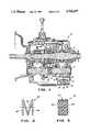
- FIG. 1is a cross sectional view of a transmission which employs two alternate preferred embodiments of the spacer of the present invention.
- FIG. 2is an isolated side view, partly in section and in a free standing mode, of one of the preferred embodiments shown in FIG. 1.
- FIG. 3is a side view, also in a free standing mode, of the other preferred embodiment shown in FIG. 1.
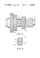
- FIG. 4is a perspective view of yet another embodiment of the spacer of the present invention for preferred use in a transmission which utilizes helical gears, as opposed to spur gears.
- FIG. 5is an isolated side view of the spacer of FIG. 4.
- a sectional view of a transmission 10includes two separate alternate embodiments of spacers made in accordance with this invention at 20 and 30, respectively.
- the transmission 10embodies a relatively standard configuration of manually shifted gears, the gears positioned on a mainshaft 8, a countershaft 14 and a non-rotatable reverse idler shaft 12.
- Each of the two spacerscircumferentially encases a portion of a transmission gear shaft.
- the spacer 20is of an open coil configuration, and circumferentially encases the reverse idler shaft 12, while the closed coil spacer 30 encases the countershaft 14.
- the open coil spacer 20is axially interposed on the reverse idler shaft 12 between a parallel set of bearings 16 and 18.
- the bearingsare needle bearings, although the spacer of the invention described herein is suitable for use with other types or styles of bearings as well.
- the bearings 16 and 18support a reverse idler gear 22, for rotation thereof about the reverse idler shaft 12 on the bearings 16 and 18.
- the open coil spacer 20defines a helicoidally shaped body portion 24, and has first and second squared ends 26 and 28, respectively.
- the squared ends 26 and 28provide for radially uniform resilient support surfaces for contact with opposing inner ends 36 and 38 of respective bearings 16 and 18.
- the shaftwill have an outside diameter slightly less than the inside diameter of the spacer. To the extent that the spacer is situated between the bearings 16 and 18, it will tend to rotate about the idler shaft 12 by virtue of friction drag forces imposed on the spacer ends 26 and 28 during rotation of the bearing inner ends 36 and 38 about the shaft 12. Thus the needle bearings 16 and 18 will frictionally cause the spacer 20 to rotate about the stationary reverse idler shaft 12. The resultant rotational movement of the helicoidal body portion 24 of the spacer 20 will produce an axial oil movement along the shaft 12 to facilitate lubrication of the needle bearings 16 and 18, which are not exposed directly to the splash and spray oil environment within the transmission 10.
- the open coil spacer 20may be disposed between the bearings 16 and 18 under a slight load; thus under a pre-loaded condition. It is suggested that the latter would insure continuous rotational movement of the spacer with the bearings about the non-rotating shaft 12. On the other hand, the spacer will move with the bearings without such pre-load, and even if there is slight axial floating of the spacer between the bearings by virtue of viscous drag forces imposed on the spacer due to surface tension of the oil.
- An alternate preferred embodiment of the spacer of the present inventiondefines a closed coil as shown at 30 in FIG. 3.
- the spacer 30, however,is positioned (see FIG. 1) between a pair of gears 32 and 34 located on the countershaft 14.
- the gears 32 and 34are keyed radially to the shaft 14, and the spacer insures the axial position of the gears with respect to one another on the shaft.
- the ends 26 and 28 of the spacer 20are squared for establishing a radially uniform support surface for contact with each of the gears. In this case, however, the contact is not resilient as there is no need for preloading of the sides of the gears 32 and 34.
- the countershaft 14is a rotatable shaft, and as a result will rotate the spacer member 30.
- the member 30is fully exposed to the splash and spray oil environment within the transmission body.
- the helicoidal body portion 24' of the spacer 30will tend to cause oil slung away from the spacer to have a slight axial, as opposed to fully radial, component.
- the closed coil spacer 30may be employed to enhance the oil dispersion within the transmission body by distributing the oil in a more desirable spray pattern.
- the spacer 30is made of non-heat treated high carbon spring steel.
- FIGS. 4 and 5An alternate preferred form of the closed coil spacer 30 is a closed coil spacer 40 as shown in FIGS. 4 and 5.
- the spacer 40has a square cross-section, and is desirable for use in transmission gear systems utilizing helical gears, as opposed to spur gears.
- Helical gearspresent end thrust loading problems due to the nature of the thrust loads imparted between the gears.
- helical gearsinvolve forces which have axial components resulting in axial thrust loads.
- the spacer members between such gearsare subject to relatively high compressive axial loads, and under such conditions, the adjacent individual coils of the round cross-sectional spacer 30 of FIG. 3 tend to cam up over themselves and collapse when employed with helical gears of the type 32' and 34' as shown in FIG. 4.
- the adjacent coils of the square cross-section spacer 40 of FIG. 5will not "cam up" and will instead tend to transmit axial thrust forces uniformly between individual coils.
- the problemis particularly exacerbated by the radial expansion to which the spacer element is subjected during normal rotation speeds of the counter-shaft.
- the counter-shaftwill typically reach speeds of up to approximately 1800 revolutions per minute, and at times may momentarily reach even higher speeds.
- FIG. 4depicts the closed coil spacer 40 as being nested between helical gears 32' and 34'.
- the latter helical gearsare counterparts of spur gears 32 and 34 of FIG. 1.
- the counter-shaft 14' of FIG. 4is a counterpart of the counter-shaft 14 of FIG. 1.
- FIG. 5shows the square cross-section 42 of the closed coil spacer 40, as well as the nature of the squared ends 44 and 46 of the spacer 40.
- the spacer ends 44 and 46parallel each other, and each is perpendicular to the longitudinal axis a--a of the spacer.
Landscapes
- Engineering & Computer Science (AREA)
- General Engineering & Computer Science (AREA)
- Mechanical Engineering (AREA)
- General Details Of Gearings (AREA)
Abstract
Description
This application is a continuation-in-part of co-pending Ser. No. 627,149 filed July 2, 1984 now abandoned.
The invention relates to spacer members positioned on transmission gear shafts for axially locating gears and bearings. The majority of standard or manually shifted transmissions are internally lubricated by "splash and spray" oil, whereby rotating members within the transmission housing extend into an oil sump at the bottom of the transmission housing and disperse oil over the internals of the transmission. Numerous efforts have been made to achieve satisfactory oil dispersions within the transmission housing; one of the more noteworthy being the use of troughs which receive oil thrown randomly for redirecting same to specific locations within the housing. One particular location of critical importance, for example, is the transmission pocket bearing. Another of such locations is the reverse idler shaft which is typically non-rotatable, but carries a reverse idler gear rotatable thereabout on needle bearings interposed between gear and shaft members. Typically, two such sets of needle bearings are utilized to support the rotation of the reverse idler gear. A spacer member is positioned between the sets of needle bearings to first axially locate the bearings, and then to insure proper rotational position of the bearings during operation. Typical spacers are generally tubular in design, and operate only to hold the bearings apart, providing no facilitation of lubrication of the bearings.
The transmission gear shaft spacer disclosed herein provides a system whereby a flow of splash and spray oil along the shaft between the bearings is facilitated. In a preferred form, the spacer has squared ends which engage a pair of bearings supporting a rotatable reverse idler gear on a non-rotatable shaft. The spacer defines a helicoidal body of an open coil configuration, the squared ends providing radially uniform support surfaces resiliently disposed between the bearings. In a preferred form the helicoidal body is of a non-heat treated high carbon steel.
A second embodiment of a transmission gear shaft spacer defines a helicoidal body of a closed coil configuration disposed tightly between a pair of gears radially fixed to a gear shaft. The spacer provides axial positioning of the gears with respect to one another. The ends of the spacer are also squared in the second preferred form.
FIG. 1 is a cross sectional view of a transmission which employs two alternate preferred embodiments of the spacer of the present invention.
FIG. 2 is an isolated side view, partly in section and in a free standing mode, of one of the preferred embodiments shown in FIG. 1.
FIG. 3 is a side view, also in a free standing mode, of the other preferred embodiment shown in FIG. 1.
FIG. 4 is a perspective view of yet another embodiment of the spacer of the present invention for preferred use in a transmission which utilizes helical gears, as opposed to spur gears.
FIG. 5 is an isolated side view of the spacer of FIG. 4.
Referring initially to FIG. 1, a sectional view of a transmission 10 includes two separate alternate embodiments of spacers made in accordance with this invention at 20 and 30, respectively. The transmission 10 embodies a relatively standard configuration of manually shifted gears, the gears positioned on a mainshaft 8, acountershaft 14 and a non-rotatablereverse idler shaft 12. Each of the two spacers circumferentially encases a portion of a transmission gear shaft. Thespacer 20 is of an open coil configuration, and circumferentially encases thereverse idler shaft 12, while the closedcoil spacer 30 encases thecountershaft 14.
Theopen coil spacer 20 is axially interposed on thereverse idler shaft 12 between a parallel set ofbearings bearings reverse idler gear 22, for rotation thereof about thereverse idler shaft 12 on thebearings
Referring now particularly to FIG. 2, theopen coil spacer 20 defines a helicoidallyshaped body portion 24, and has first and secondsquared ends squared ends inner ends respective bearings bearings idler shaft 12 by virtue of friction drag forces imposed on thespacer ends inner ends shaft 12. Thus theneedle bearings spacer 20 to rotate about the stationaryreverse idler shaft 12. The resultant rotational movement of thehelicoidal body portion 24 of thespacer 20 will produce an axial oil movement along theshaft 12 to facilitate lubrication of theneedle bearings
It should be noted that theopen coil spacer 20 may be disposed between thebearings non-rotating shaft 12. On the other hand, the spacer will move with the bearings without such pre-load, and even if there is slight axial floating of the spacer between the bearings by virtue of viscous drag forces imposed on the spacer due to surface tension of the oil.
An alternate preferred embodiment of the spacer of the present invention defines a closed coil as shown at 30 in FIG. 3. Thespacer 30, however, is positioned (see FIG. 1) between a pair ofgears countershaft 14. Thegears shaft 14, and the spacer insures the axial position of the gears with respect to one another on the shaft. Similarly to theends spacer 20, theends 26' and 28' of thespacer 30 are squared for establishing a radially uniform support surface for contact with each of the gears. In this case, however, the contact is not resilient as there is no need for preloading of the sides of thegears
It will be appreciated by those skilled in the art that thecountershaft 14 is a rotatable shaft, and as a result will rotate thespacer member 30. Themember 30 is fully exposed to the splash and spray oil environment within the transmission body. Those skilled in the art will appreciate the fact that the helicoidal body portion 24' of thespacer 30 will tend to cause oil slung away from the spacer to have a slight axial, as opposed to fully radial, component. As a result, the closedcoil spacer 30 may be employed to enhance the oil dispersion within the transmission body by distributing the oil in a more desirable spray pattern. Again, in a preferred form, thespacer 30 is made of non-heat treated high carbon spring steel.
An alternate preferred form of the closedcoil spacer 30 is a closedcoil spacer 40 as shown in FIGS. 4 and 5. Thespacer 40 has a square cross-section, and is desirable for use in transmission gear systems utilizing helical gears, as opposed to spur gears. Helical gears present end thrust loading problems due to the nature of the thrust loads imparted between the gears. Hence helical gears involve forces which have axial components resulting in axial thrust loads. The result is that the spacer members between such gears are subject to relatively high compressive axial loads, and under such conditions, the adjacent individual coils of theround cross-sectional spacer 30 of FIG. 3 tend to cam up over themselves and collapse when employed with helical gears of the type 32' and 34' as shown in FIG. 4. By contrast, the adjacent coils of thesquare cross-section spacer 40 of FIG. 5 will not "cam up" and will instead tend to transmit axial thrust forces uniformly between individual coils.
The problem is particularly exacerbated by the radial expansion to which the spacer element is subjected during normal rotation speeds of the counter-shaft. The counter-shaft will typically reach speeds of up to approximately 1800 revolutions per minute, and at times may momentarily reach even higher speeds.
FIG. 4 depicts the closedcoil spacer 40 as being nested between helical gears 32' and 34'. The latter helical gears are counterparts ofspur gears counter-shaft 14 of FIG. 1.
FIG. 5 shows thesquare cross-section 42 of the closedcoil spacer 40, as well as the nature of thesquared ends spacer 40. Ideally, the spacer ends 44 and 46 parallel each other, and each is perpendicular to the longitudinal axis a--a of the spacer.
Although only four preferred embodiments of the spacer of the present invention have been described and shown herein, there are many variations of the invention which are envisioned to fall within the scope of the following apended claims.
Claims (4)
1. A spacer disposed for circumferentially encasing a non-rotatable transmission gear shaft, said spacer comprising a helicoidal body portion defining an open coil, said body portion having ends resiliently disposed between a pair of bearings rotatably supported on said shaft, said bearings supporting a gear rotatable about said non-rotatable shaft, said body portion being radially encased by said gear, said body portion causing a unidirectional axial flow of splash and spray oil along said shaft between said rotating bearings thereby defining an axial flow pumping means, said ends of said coil being squared and defining radially uniform resilient support surfaces for contact with opposing ends of said bearings, said shaft having an outside diameter slightly less than the inside diameter of the spacer, whereby as said bearings rotate about said non-rotatable shaft, said spacer rotates about said shaft with said bearings.
2. The spacer of claim 1 wherein said shaft is a non-rotatable reverse idler shaft, and wherein the shaft contains a rotatable gear supported on said non-rotatable shaft radially outwardly of said spacer, whereby said splash and spray oil is urged through said bearings disposed either side of said spacer by said helicoidal body portion of said spacer.
3. The spacer of claim 2 wherein said helicoidal body portion is a non-heat treated, high carbon spring steel.
4. The spacer of claim 3 wherein said squared ends are disposed for making resilient contact with needle bearings.
Priority Applications (1)
| Application Number | Priority Date | Filing Date | Title |
|---|---|---|---|
| US06/826,169US4765197A (en) | 1984-07-02 | 1986-02-06 | Spacer for transmission shaft |
Applications Claiming Priority (2)
| Application Number | Priority Date | Filing Date | Title |
|---|---|---|---|
| US62714984A | 1984-07-02 | 1984-07-02 | |
| US06/826,169US4765197A (en) | 1984-07-02 | 1986-02-06 | Spacer for transmission shaft |
Related Parent Applications (1)
| Application Number | Title | Priority Date | Filing Date |
|---|---|---|---|
| US62714984AContinuation-In-Part | 1984-07-02 | 1984-07-02 |
Publications (1)
| Publication Number | Publication Date |
|---|---|
| US4765197Atrue US4765197A (en) | 1988-08-23 |
Family
ID=27090347
Family Applications (1)
| Application Number | Title | Priority Date | Filing Date |
|---|---|---|---|
| US06/826,169Expired - Fee RelatedUS4765197A (en) | 1984-07-02 | 1986-02-06 | Spacer for transmission shaft |
Country Status (1)
| Country | Link |
|---|---|
| US (1) | US4765197A (en) |
Cited By (6)
| Publication number | Priority date | Publication date | Assignee | Title |
|---|---|---|---|---|
| US5505102A (en)* | 1993-11-23 | 1996-04-09 | Eaton Corporation | Idler gear mounting arrangement |
| DE19904479A1 (en)* | 1999-02-04 | 2000-08-10 | Zahnradfabrik Friedrichshafen | Step change gear |
| DE19954130A1 (en)* | 1999-11-11 | 2001-05-17 | Zahnradfabrik Friedrichshafen | Step change gear |
| DE10118646A1 (en)* | 2001-04-14 | 2002-10-17 | Zahnradfabrik Friedrichshafen | Staged-shift transmission with tooth measurements in specified relation to axial spacing |
| US20100130671A1 (en)* | 2007-03-15 | 2010-05-27 | Jsr Corporation | Conjugated diolefin copolymer rubber, method for producing the same, rubber composition and tire |
| GB2471996A (en)* | 2009-07-17 | 2011-01-26 | Gm Global Tech Operations Inc | A double clutch transmission with pinion mounted via a bearing |
Citations (13)
| Publication number | Priority date | Publication date | Assignee | Title |
|---|---|---|---|---|
| US1532557A (en)* | 1922-09-15 | 1925-04-07 | William C Durant | Rear axle |
| US1553767A (en)* | 1924-10-27 | 1925-09-15 | Ralph E Fulton | Grease retainer |
| US1749247A (en)* | 1922-06-14 | 1930-03-04 | Electric Service Supplies Co | Lubricating system |
| US2192088A (en)* | 1937-03-25 | 1940-02-27 | Spicer Mfg Corp | Needle bearing differential |
| US2240118A (en)* | 1937-10-19 | 1941-04-29 | Mack Mfg Corp | Oiling device for driving pinion bearings |
| US2681126A (en)* | 1950-03-31 | 1954-06-15 | Searls Edward Charles | Lubrication of gearing |
| US2935889A (en)* | 1957-11-12 | 1960-05-10 | Allis Chalmers Mfg Co | Lubrication of transmission clutch disks |
| US3083790A (en)* | 1961-06-15 | 1963-04-02 | Int Harvester Co | Lubricating means for a power transmission |
| US4240524A (en)* | 1978-08-02 | 1980-12-23 | Toyota Jidosha Kogyo Kabushiki Kaisha | Oil flow control device for power transmissions |
| US4319499A (en)* | 1977-10-18 | 1982-03-16 | Toyota Jidosha Kogyo Kabushiki Kaisha | Lubricating device for final drive gearing of power transmission unit |
| US4359909A (en)* | 1980-04-03 | 1982-11-23 | Toyota Jidosha Kogyo Kabushiki Kaisha | Transmission |
| US4429587A (en)* | 1981-09-10 | 1984-02-07 | General Electric Company | Attitude insensitive lubrication systems |
| US4559023A (en)* | 1983-03-23 | 1985-12-17 | Honda Giken Kogyo Kabushiki Kaisha | Torque damper |
- 1986
- 1986-02-06USUS06/826,169patent/US4765197A/ennot_activeExpired - Fee Related
Patent Citations (13)
| Publication number | Priority date | Publication date | Assignee | Title |
|---|---|---|---|---|
| US1749247A (en)* | 1922-06-14 | 1930-03-04 | Electric Service Supplies Co | Lubricating system |
| US1532557A (en)* | 1922-09-15 | 1925-04-07 | William C Durant | Rear axle |
| US1553767A (en)* | 1924-10-27 | 1925-09-15 | Ralph E Fulton | Grease retainer |
| US2192088A (en)* | 1937-03-25 | 1940-02-27 | Spicer Mfg Corp | Needle bearing differential |
| US2240118A (en)* | 1937-10-19 | 1941-04-29 | Mack Mfg Corp | Oiling device for driving pinion bearings |
| US2681126A (en)* | 1950-03-31 | 1954-06-15 | Searls Edward Charles | Lubrication of gearing |
| US2935889A (en)* | 1957-11-12 | 1960-05-10 | Allis Chalmers Mfg Co | Lubrication of transmission clutch disks |
| US3083790A (en)* | 1961-06-15 | 1963-04-02 | Int Harvester Co | Lubricating means for a power transmission |
| US4319499A (en)* | 1977-10-18 | 1982-03-16 | Toyota Jidosha Kogyo Kabushiki Kaisha | Lubricating device for final drive gearing of power transmission unit |
| US4240524A (en)* | 1978-08-02 | 1980-12-23 | Toyota Jidosha Kogyo Kabushiki Kaisha | Oil flow control device for power transmissions |
| US4359909A (en)* | 1980-04-03 | 1982-11-23 | Toyota Jidosha Kogyo Kabushiki Kaisha | Transmission |
| US4429587A (en)* | 1981-09-10 | 1984-02-07 | General Electric Company | Attitude insensitive lubrication systems |
| US4559023A (en)* | 1983-03-23 | 1985-12-17 | Honda Giken Kogyo Kabushiki Kaisha | Torque damper |
Cited By (10)
| Publication number | Priority date | Publication date | Assignee | Title |
|---|---|---|---|---|
| US5505102A (en)* | 1993-11-23 | 1996-04-09 | Eaton Corporation | Idler gear mounting arrangement |
| DE19904479A1 (en)* | 1999-02-04 | 2000-08-10 | Zahnradfabrik Friedrichshafen | Step change gear |
| DE19954130A1 (en)* | 1999-11-11 | 2001-05-17 | Zahnradfabrik Friedrichshafen | Step change gear |
| US6668670B1 (en) | 1999-11-11 | 2003-12-30 | Zf Friedrichshafen Ag | Step-change gearbox |
| DE10118646A1 (en)* | 2001-04-14 | 2002-10-17 | Zahnradfabrik Friedrichshafen | Staged-shift transmission with tooth measurements in specified relation to axial spacing |
| US20100130671A1 (en)* | 2007-03-15 | 2010-05-27 | Jsr Corporation | Conjugated diolefin copolymer rubber, method for producing the same, rubber composition and tire |
| US8022129B2 (en) | 2007-03-15 | 2011-09-20 | Jsr Corporation | Conjugated diolefin copolymer rubber, method for producing the same, rubber composition and tire |
| GB2471996A (en)* | 2009-07-17 | 2011-01-26 | Gm Global Tech Operations Inc | A double clutch transmission with pinion mounted via a bearing |
| US20110088509A1 (en)* | 2009-07-17 | 2011-04-21 | Gm Global Technology Operations, Inc. | Double-clutch transmission for vehicles |
| GB2471996B (en)* | 2009-07-17 | 2015-11-04 | Gm Global Tech Operations Inc | Double-clutch transmission for vehicles |
Similar Documents
| Publication | Publication Date | Title |
|---|---|---|
| US6004239A (en) | Friction type continuously variable speed changing mechanism | |
| US4756212A (en) | Planet gear carrier assembly | |
| CA1304603C (en) | Twin countershaft transmission with floating main shaft | |
| US6824495B1 (en) | Planetary gear for mounting on an electromotor | |
| US3223196A (en) | Motor vehicle gearbox and pump | |
| CN101493117A (en) | Bearing assembly for planetary gear pinion | |
| US3316035A (en) | Needle bearing and retainer assembly for gears | |
| US4765197A (en) | Spacer for transmission shaft | |
| KR20120081989A (en) | Spacer for a radial needle roller bearing | |
| JP2007218369A (en) | Roller bearing for planetary gear mechanism | |
| US5810116A (en) | Bearing lubrication mechanism | |
| JP2804295B2 (en) | Carrier assembly of planetary gear set | |
| CA1251660A (en) | Spacer for transmission shaft | |
| US5655410A (en) | Worm type reduction gear mechanism | |
| JPS55163320A (en) | Rotational device | |
| US5306090A (en) | Sliding roller bearing having rolling members | |
| JP2593528B2 (en) | Oil-impregnated plain bearing | |
| US8678665B2 (en) | Bearing arrangement for heavy duty marine transmission | |
| US4273003A (en) | Check valve bearing lubricator | |
| JP2604564Y2 (en) | Planetary gear set | |
| JPS5911043B2 (en) | Bidirectional thrust and radial ball bearing | |
| JP2016200218A (en) | Planetary roller type power transmission device | |
| US1402458A (en) | Clutch-throw-out bearing mounting | |
| JP2005076810A (en) | Cage for needle roller bearing and needle roller bearing | |
| US2157259A (en) | Variable speed transmission |
Legal Events
| Date | Code | Title | Description |
|---|---|---|---|
| AS | Assignment | Owner name:DANA CORPORATION, TOLEDO, OHIO A CORP. OF VA. Free format text:ASSIGNMENT OF ASSIGNORS INTEREST.;ASSIGNOR:YARNELL, JAMES A.;REEL/FRAME:004552/0230 Effective date:19860204 Owner name:DANA CORPORATION, OHIO Free format text:ASSIGNMENT OF ASSIGNORS INTEREST;ASSIGNOR:YARNELL, JAMES A.;REEL/FRAME:004552/0230 Effective date:19860204 | |
| FPAY | Fee payment | Year of fee payment:4 | |
| FPAY | Fee payment | Year of fee payment:8 | |
| REMI | Maintenance fee reminder mailed | ||
| AS | Assignment | Owner name:TRANSMISIONES TSP, S.A. DE C.V., MEXICO Free format text:ASSIGNMENT OF ASSIGNORS INTEREST;ASSIGNOR:DANA CORPORATION;REEL/FRAME:010841/0037 Effective date:19970902 | |
| LAPS | Lapse for failure to pay maintenance fees | ||
| FP | Lapsed due to failure to pay maintenance fee | Effective date:20000823 | |
| STCH | Information on status: patent discontinuation | Free format text:PATENT EXPIRED DUE TO NONPAYMENT OF MAINTENANCE FEES UNDER 37 CFR 1.362 |