US4764840A - Dual limit solenoid driver control circuit - Google Patents
Dual limit solenoid driver control circuitDownload PDFInfo
- Publication number
- US4764840A US4764840AUS06/911,946US91194686AUS4764840AUS 4764840 AUS4764840 AUS 4764840AUS 91194686 AUS91194686 AUS 91194686AUS 4764840 AUS4764840 AUS 4764840A
- Authority
- US
- United States
- Prior art keywords
- solenoid
- current
- pull
- maximum
- minimum
- Prior art date
- Legal status (The legal status is an assumption and is not a legal conclusion. Google has not performed a legal analysis and makes no representation as to the accuracy of the status listed.)
- Expired - Lifetime
Links
- 230000009977dual effectEffects0.000titleabstractdescription4
- 230000004044responseEffects0.000claimsdescription9
- 230000008878couplingEffects0.000claims4
- 238000010168coupling processMethods0.000claims4
- 238000005859coupling reactionMethods0.000claims4
- 230000005284excitationEffects0.000abstract1
- 230000001351cycling effectEffects0.000description5
- 230000000694effectsEffects0.000description3
- 230000004048modificationEffects0.000description3
- 238000012986modificationMethods0.000description3
- 230000009467reductionEffects0.000description2
- 230000008859changeEffects0.000description1
- 238000010276constructionMethods0.000description1
- 125000004122cyclic groupChemical group0.000description1
- 230000007812deficiencyEffects0.000description1
- 238000010586diagramMethods0.000description1
- 230000000977initiatory effectEffects0.000description1
Images

Classifications
- H—ELECTRICITY
- H01—ELECTRIC ELEMENTS
- H01H—ELECTRIC SWITCHES; RELAYS; SELECTORS; EMERGENCY PROTECTIVE DEVICES
- H01H47/00—Circuit arrangements not adapted to a particular application of the relay and designed to obtain desired operating characteristics or to provide energising current
- H01H47/22—Circuit arrangements not adapted to a particular application of the relay and designed to obtain desired operating characteristics or to provide energising current for supplying energising current for relay coil
- H01H47/32—Energising current supplied by semiconductor device
- H01H47/325—Energising current supplied by semiconductor device by switching regulator
Definitions
- the present inventionis related to inductor current controllers, and more specifically to solenoid current controllers.
- An object of the present inventionis to provide an improved solenoid driver control circuit which overcomes the above-noted deficiencies of prior circuits.
- an improved solenoid driver control circuitcomprises: a control signal input terminal for receiving a control signal; current sense means for providing a current sense signal indicative of current flowing through a solenoid; solenoid driver means having a first operable state such that current can flow through said solenoid from a power source and a second operable state such that current effectively cannot flow from said power source through said solenoid; two separate threshold comparator means, each for comparing at least one received reference threshold input signal with said current sense signal and each for providing an output signal in response thereto to control said solenoid driver means; pull-in current means for responding to said control signal by initially providing, for a predetermined pull-in period of time independent of said current sense signal, a pair of predetermined maximum and minimum first thresholds, each of said separate threshold comparator means receiving an associated one of said pair of maximum and minimum first thresholds, said pair of first thresholds causing said comparator means to implement pull-in maximum and minimum current limits for said solenoid current during said predetermined pull-
- the switching thresholdsare fixed and independent of the magnitude of solenoid current during the pull-in and hold periods of time.
- the maximum first thresholdexceeds the maximum second threshold and similarly the minimum first threshold exceeds the minimum second threshold.
- the outputs of the two threshold comparatorsare provided as effective inputs to the set and reset terminals of a flip flop circuit whose output provides a signal to control the solenoid driver means.
- FIG. 1is a schematic diagram of a dual limit solenoid current controller circuit constructed in accordance with the present invention.
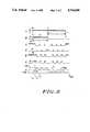
- FIG. 2is a series of graphs A through G which illustrate signal waveforms provided at various terminals of the circuit shown in FIG. 1.
- a dual limit solenoid current controller circuit 10is illustrated.
- the circuitincludes an input terminal 11 at which a control signal is received wherein actuation of a solenoid 12, illustrated in FIG. 1 by a solenoid inductance 12, is implemented in response to the control signal.
- the terminal 11is connected as an input to an effective AND gate 13 which provides an output at a terminal 14 that is coupled as an input to a solenoid driver stage 15 connected between a positive battery voltage terminal 16 and the solenoid inductor 12.
- a flyback control device 17is also connected to the solenoid 12 so as to implement flyback voltage control for energy stored in the solenoid inductor.
- the solenoid 12is connected through a current sensing resistor 18 to ground potential, and a power source comprising a battery 19 is connected between the terminal 16 and ground potential.
- signals at the terminal 14switch the solenoid driver stage 15 on and off such that when the driver stage 15 is on, current can flow through the solenoid inductor 12 from the power source battery 19, and when the driver stage 15 is off, current cannot effectively flow through the solenoid from the power source.
- the operation of the flyback control device 17 to recirculate current produced by energy stored in the solenoidis well understood to those of skill in the art and, therefore, will not be further explained.
- the connection between the solenoid 12 and the sensing resistor 18is provided at a terminal 20 that is coupled through a calibration resistor divider network comprising resistors 21 and 22 to a terminal 23.
- the terminal 23is directly connected to the noninverting input of a DC comparator 24 and to the inverting input of a DC comparator 25.
- the DC comparators 24 and 25are substantially identical in construction.
- a resistor divider networkis provided between a low voltage power supply terminal 26 and ground potential wherein a resistor 27 is connected between the terminal 26 and a terminal 28 corresponding to the inverting input of the comparator 24.
- a resistor 29is connected between the terminal 28 and a terminal 30 corresponding to the noninverting input of the comparator 25.
- a resistor 31is connected between the terminal 30 and ground potential.
- the resistor divider comprising the resistors 27, 29 and 31will essentially selectively provide maximum and minimum first and second threshold levels to the comparators 24 and 25 in accordance with the present invention as will be subsequently discussed.
- the output of the comparator 24is connected to a reset terminal R of a set/reset flip flop circuit 32, and the output of the comparator 25 is connected to a set terminal S of the flip flop.
- An output terminal Q of the flip flop 32is connected as an input to the AND gate 13.
- a monostable multivibrator 33has an input terminal 34 directly connected to the terminal 11 and provides an output signal at a terminal 35. The terminal 35 and the signal thereat are coupled through a scaling resistor 36 to the terminal 30.
- Graph A in FIG. 2represents a control signal 40 provided at the input terminal 11 of the system shown in FIG. 1.
- a low signal levelis present which results in the driver stage 15 preventing current flow from the battery 19 through the solenoid 12.
- the driver stage 15represents an open circuit so as to prevent solenoid current flow.
- a positive pulse 41 of predetermined lengthcommences for the signal 40 wherein during this pulse, actuation of the solenoid 12 is desired.
- the monostable multivibrator 33produces an output pulse 43 of a signal 44 having a predetermined time duration T1 corresponding to a "pull-in" time period.
- the monostable 33produces the output pulse 43 which, via the scaling resistor 36, produces a voltage pulse at the terminal 30.
- the signal 44is schematically represented by the graph B in FIG. 2.
- Graph G in FIG. 2is representative of the voltage at the terminal 20 which essentially corresponds to a current sense signal 45.
- the voltage at the terminal 20 representative of sensed solenoid current, which is sensed by the resistor 18,is 0. Since a low voltage is provided at the terminal 20 prior to t 0 , this results in the comparator 25 producing a high output setting flip flop 32 since the voltage at the terminal 30 will exceed the current sense related signal provided at the terminal 23.
- the output of the comparator 25corresponds to a signal 46 illustrated in graph C in FIG. 2. Since the voltage at the terminal 23 is low (zero) at the time t 0 , this results in the comparator 24 providing a low output at this time to the reset terminal R of the flip flop 32. The output of the comparator 24 is illustrated in graph D of FIG. 2 as signal 47. The end result is that at the time t 0 , the flip flop 32 will be set such that the signal at its output terminal Q will be high wherein this signal corresponds to the signal 48 illustrated in graph E in FIG. 2.
- the signal 48provides one input to the AND gate 13, and the signal 40 at the terminal 11 provides the other input, this results in the output of the AND gate 13, at terminal 14, switching from low to high at the time t 0 .
- the signal at the terminal 14is illustrated in graph F of FIG. 2 as the signal 49.
- the end resultis that a high signal is provided as an input to the driver stage 15 via the terminal 14. This results in effectively closing a switch in stage 15 which connects the battery 19 to the solenoid 12 and results in the initiation of solenoid current such that the current sense signal 45 will begin to rise after t 0 .
- the voltage at the terminal 23will increase wherein this voltage varies in substantially the same manner as the signal 45 at the terminal 20.
- the output of the monostable multivibrator 33results in predetermined fixed reference voltages being provided at the terminals 28 and 30 wherein these voltages comprise reference threshold voltages applied to the separate comparators 24 and 25.
- these voltagescomprise reference threshold voltages applied to the separate comparators 24 and 25.
- the signal at the terminal 23will essentially pass the fixed reference voltage being maintained at the terminal 30, and this will result in the signal 46 at the set terminal S of the flip flop going low. This occurs at t 1 .
- thishas no effect on circuit operations since the output 48 of the flip flop 32 remains in a high state. This is readily visualized in graph G in FIG. 2 by the signal 45 exceeding a reference current level corresponding to an initial minimum level I min .
- the solenoid current represented by the signal 45will continue to increase until an initial maximum reference level I max is achieved at a time t 2 at which time the comparator 24 will produce an output pulse since the voltage at the terminal 23 will now exceed the voltage at the reference terminal 28.
- the flip flop 32will be reset such that its output 48 will be a low state, and this results in essentially opening the connection between the battery 19 and the solenoid 12.
- the flyback control device 17implements control of the current recirculation maintained by the solenoid inductance, and solenoid current begins to decrease as is generally illustrated by the reduction in the signal 45 shown in graph G.
- the monostable 33ceases to provide any voltage pulse to the terminal 30.
- the effect of thisis to implement holding maximum and holding minimum current thresholds H max and H min for the solenoid current wherein these levels are generally illustrated in graph G of FIG. 2.
- the solenoid currentwill vary cyclically due to the operation of the comparators 24 and 25, but now the maximum and minimum holding thresholds for solenoid current are lower than the corresponding maximum and minimum solenoid current threshold levels provided during the initial pull-in period.
- the maximum and minimum reference threshold levels for both the pull-in period and the hold periodare provided at the terminals 28 and 30 wherein during the pull-in period higher fixed levels are provided due to the operation of the monostable multivibrator 33, whereas during the hold period lower fixed threshold levels are provided.
- the control circuitincludes the control terminal 11 at which the control signal 40 is provided, as well as the current sensing resistor 18 that produces the sense signals at the terminals 20 and 23 that are representative of current flowing through the solenoid 12.
- the solenoid driver stage 15is essentially operable in first and second states such that in on and off conditions it will selectively connect and disconnect the battery power source 19 to the solenoid 12.
- Two separate threshold comparators 24 and 25are provided with each of these comparing at least one received fixed reference threshold input signal, provided by the voltage divider comprising the resistors 27, 29 and 31, with a current sense signal representative of the voltage at the terminal 23.
- the outputs of each of these comparatorsare coupled through the flip flop 32 so as to provide control of the solenoid driver stage 15.
- the present inventionhas provided an effective pull-in current means, which includes the monostable 33, that responds to the control signal at the terminal 11 for providing a predetermined pull-in period of time which is independent of the magnitude of the sensed solenoid current.
- the present pull-in current meansessentially provides initial maximum and minimum first fixed reference thresholds to each of the comparators 24 and 25 wherein these thresholds are also independent of the sensed solenoid current. The effect of this is to cause the comparators 24 and 25 to implement pull-in or initial maximum and minimum current limits for the solenoid current during the predetermined pull-in period of time T 1 .
- the present inventionhas also provided a holding current means which essentially corresponds to the operation of the resistor divider, comprising the resistors 27, 29 and 31, in the absence of the existence of the output pulse produced by the monostable 33 during the pull-in time period.
- This holding current meanswill essentially implement a predetermined pair of maximum/minimum second fixed reference thresholds corresponding to the holding current maximum and minimum thresholds illustrated in graph G in FIG. 2 during the hold time period T 2 .
- the second thresholdsrather than the first thresholds, are provided as inputs to the comparators 24 and 25 wherein the second thresholds define the hold cycle maximum and minimum current limits for the solenoid current during the hold time period.
- a feature of the present inventionis that the switching thresholds during the pull-in time and the hold time are each fixed and independent of the magnitude of the solenoid current. Many prior systems do not have this feature and, therefore, suffer from stability problems since variations in solenoid current will cause variations in the reference threshold voltages applied to the comparators 24 and 25 which are responsible for accurately determining the current switching thresholds.
- the present inventionprovides both the maximum and minimum thresholds of the cycling of the solenoid current during the pull-in period, as well as the maximum and minimum thresholds of cycling of the solenoid current during the holding period, and this is accomplished with a minimum number of components since pairs of maximum and minimum thresholds are readily provided by a single voltage divider by virtue of only a single additional connection to the voltage divider via the monostable 33 and resistor 36.
- Proper design of the control circuit of the present inventionenables the selection of totally different maximum and minimum thresholds for the pull-in and holding periods of time with the maximum pull-in threshold exceeding the maximum holding reference threshold and the minimum pull-in reference threshold exceeding the minimum holding reference threshold.
- Many prior systemsdo not have this circuit design flexibility since they cannot readily provide four different reference thresholds without extensive circuit redesign, and typically prior systems do not suggest the desirability of providing this design flexibility.
- many of the components noted in the present control circuitcan be readily implemented on an integrated circuit, shown dashed as component 50 in FIG. 1, and it is apparent that the present invention provides for a simplified implementation of the desired cyclic variation of solenoid current during the pull-in and holding periods of time.
Landscapes
- Engineering & Computer Science (AREA)
- Power Engineering (AREA)
- Magnetically Actuated Valves (AREA)
Abstract
Description
The present invention is related to inductor current controllers, and more specifically to solenoid current controllers.
It is known that it is generally desirable to implement actuation of a solenoid by providing an initial or pull-in period of time during which a maximum first current is effectively passed through the solenoid inductor to achieve initial actuation of the solenoid. Subsequently, a smaller magnitude solenoid current is implemented so as to maintain actuation of the solenoid wherein this occurs during a subsequent holding or hold period of time. In this manner, the efficiency of the solenoid controller is increased since only the minimum necessary holding current is utilized by the solenoid for maintaining solenoid actuation whereas a high pull-in or actuation current is initially permitted to insure the rapid response of the solenoid to a solenoid actuation control pulse.
Many prior circuits have implemented the general features of the solenoid current control system discussed above. Some of these systems determine the pull-in time, during which a high value of solenoid current can be drawn, by use of a monostable multivibrator. These systems typically utilize additional monostable multivibrators for implementing cycling of the solenoid current about a first high pull-in level and then about a low holding current level. This cycling is implemented by essentially opening and closing the connection between the solenoid coil and a power supply such that during the pull-in period solenoid current varies between maximum and minimum initial high current levels, and during the holding current period solenoid current varies maximum and minimum lower holding current levels. However, the prior systems which utilize monostable multivibrators for determining when such cycling is to occur between the maximum and minimum current levels are not believed to be sufficiently accurate. This is because there is no direct control of the maximum/minimum current levels of the solenoid current, and therefore other circuit parameters can substantially affect the actual solenoid current level regardless of the accuracy of the monostable multivibrators.
While some prior systems have sensed solenoid current directly and have utilized comparators which react to both the sensed solenoid current and current limit reference thresholds so as to control the variation of solenoid current, typically these systems utilize hysteresis to implement the desired switching between maximum and minimum current levels. This use of hysteresis can present stability problems due to temperature variation of the feedback gain which implements the hysteresis. In addition, the use of hysteresis generally results in the reference threshold levels being a function of the sensed solenoid current, and this again is not believed to be a desirable result. Circuit stability would be enhanced if reference thresholds for comparators are fixed during critical operating cycles. In addition, in some systems the pull-in period of time during which a relatively high current for the solenoid is permitted is a function of the sensed solenoid current, and this can lead to variable circuit performance which would be undesired.
In addition to the above disadvantages of prior circuits, typically the circuitry required for implementation of such prior systems is relatively complex, and circuit design flexibility enabling the selection of different maximum and minimum current limits during the pull-in and hold periods is difficult to achieve.
An object of the present invention is to provide an improved solenoid driver control circuit which overcomes the above-noted deficiencies of prior circuits.
In one embodiment of the present invention, an improved solenoid driver control circuit is provided. The control circuit comprises: a control signal input terminal for receiving a control signal; current sense means for providing a current sense signal indicative of current flowing through a solenoid; solenoid driver means having a first operable state such that current can flow through said solenoid from a power source and a second operable state such that current effectively cannot flow from said power source through said solenoid; two separate threshold comparator means, each for comparing at least one received reference threshold input signal with said current sense signal and each for providing an output signal in response thereto to control said solenoid driver means; pull-in current means for responding to said control signal by initially providing, for a predetermined pull-in period of time independent of said current sense signal, a pair of predetermined maximum and minimum first thresholds, each of said separate threshold comparator means receiving an associated one of said pair of maximum and minimum first thresholds, said pair of first thresholds causing said comparator means to implement pull-in maximum and minimum current limits for said solenoid current during said predetermined pull-in period of time; and holding current means for providing, for a hold time after said predetermined pull-in period of time, a pair of predetermined maximum and minimum second thresholds, each of said separate threshold comparator means receiving an associated one of said second thresholds during said hold time rather than said first thresholds, wherein during said hold time said pair of second thresholds define hold cycle maximum and minimum current limits for said solenoid current during said hold time.
Preferably in the solenoid driver control circuit recited above, the switching thresholds are fixed and independent of the magnitude of solenoid current during the pull-in and hold periods of time. In addition, the maximum first threshold exceeds the maximum second threshold and similarly the minimum first threshold exceeds the minimum second threshold. Preferably, the outputs of the two threshold comparators are provided as effective inputs to the set and reset terminals of a flip flop circuit whose output provides a signal to control the solenoid driver means. An effective implementation of the solenoid driver control circuit discussed above is provided by the use of a monostable multivibrator which responds to the control signal at the input terminal and produces an output pulse, defining the pull-in period, which is then coupled as an input to a resistor divider circuit which provides the maximum and minimum thresholds to each of the separate comparators. This circuit configuration can be readily implemented in an integrated circuit design and has improved stability and performance characteristics with respect to previous circuit implementations, as well as providing circuit design flexibility to set the pull-in and hold thresholds.
For a more complete understanding of the present invention, reference should be made to the drawings in which:
FIG. 1 is a schematic diagram of a dual limit solenoid current controller circuit constructed in accordance with the present invention; and
FIG. 2 is a series of graphs A through G which illustrate signal waveforms provided at various terminals of the circuit shown in FIG. 1.
Referring to FIG. 1, a dual limit solenoidcurrent controller circuit 10 is illustrated. The circuit includes aninput terminal 11 at which a control signal is received wherein actuation of asolenoid 12, illustrated in FIG. 1 by asolenoid inductance 12, is implemented in response to the control signal.
Theterminal 11 is connected as an input to aneffective AND gate 13 which provides an output at aterminal 14 that is coupled as an input to asolenoid driver stage 15 connected between a positivebattery voltage terminal 16 and thesolenoid inductor 12. Aflyback control device 17 is also connected to thesolenoid 12 so as to implement flyback voltage control for energy stored in the solenoid inductor. Thesolenoid 12 is connected through acurrent sensing resistor 18 to ground potential, and a power source comprising abattery 19 is connected between theterminal 16 and ground potential.
Essentially, signals at theterminal 14 switch thesolenoid driver stage 15 on and off such that when thedriver stage 15 is on, current can flow through thesolenoid inductor 12 from thepower source battery 19, and when thedriver stage 15 is off, current cannot effectively flow through the solenoid from the power source. The operation of theflyback control device 17 to recirculate current produced by energy stored in the solenoid is well understood to those of skill in the art and, therefore, will not be further explained.
The connection between thesolenoid 12 and thesensing resistor 18 is provided at aterminal 20 that is coupled through a calibration resistor dividernetwork comprising resistors terminal 23. Theterminal 23 is directly connected to the noninverting input of aDC comparator 24 and to the inverting input of aDC comparator 25. TheDC comparators power supply terminal 26 and ground potential wherein aresistor 27 is connected between theterminal 26 and aterminal 28 corresponding to the inverting input of thecomparator 24. Aresistor 29 is connected between theterminal 28 and aterminal 30 corresponding to the noninverting input of thecomparator 25. Aresistor 31 is connected between theterminal 30 and ground potential. The resistor divider comprising theresistors comparators
The output of thecomparator 24 is connected to a reset terminal R of a set/resetflip flop circuit 32, and the output of thecomparator 25 is connected to a set terminal S of the flip flop. An output terminal Q of theflip flop 32 is connected as an input to theAND gate 13. Amonostable multivibrator 33 has aninput terminal 34 directly connected to theterminal 11 and provides an output signal at aterminal 35. Theterminal 35 and the signal thereat are coupled through ascaling resistor 36 to theterminal 30. The operation of the above-noted circuit configuration will now be discussed in conjunction with the circuit waveforms shown in FIG. 2 wherein the vertical axis of these waveforms represents magnitude and the horizontal axis is representative of time.
Graph A in FIG. 2 represents acontrol signal 40 provided at theinput terminal 11 of the system shown in FIG. 1. Prior to an initial time t0, a low signal level is present which results in thedriver stage 15 preventing current flow from thebattery 19 through thesolenoid 12. In other words, thedriver stage 15 represents an open circuit so as to prevent solenoid current flow. At the time t0, apositive pulse 41 of predetermined length commences for thesignal 40 wherein during this pulse, actuation of thesolenoid 12 is desired. In response to a leadingedge 42 of this positive pulse of thesignal 40, themonostable multivibrator 33 produces anoutput pulse 43 of asignal 44 having a predetermined time duration T1 corresponding to a "pull-in" time period. During this pull-in time period, an effective relatively high current is allowed to flow in thesolenoid 12 to insure rapid actuation of the solenoid. Subsequently during a hold period T2, a lower current level will effectively be provided for thesolenoid 12 so as to maintain the solenoid in an actuated state. This is accomplished in the following manner.
Essentially, the monostable 33 produces theoutput pulse 43 which, via thescaling resistor 36, produces a voltage pulse at theterminal 30. Thesignal 44 is schematically represented by the graph B in FIG. 2. Graph G in FIG. 2 is representative of the voltage at theterminal 20 which essentially corresponds to acurrent sense signal 45. At the time t0, there is no current flowing in thesolenoid 12, and, therefore, the voltage at theterminal 20 representative of sensed solenoid current, which is sensed by theresistor 18, is 0. Since a low voltage is provided at theterminal 20 prior to t0, this results in thecomparator 25 producing a high outputsetting flip flop 32 since the voltage at theterminal 30 will exceed the current sense related signal provided at theterminal 23. The output of thecomparator 25 corresponds to asignal 46 illustrated in graph C in FIG. 2. Since the voltage at theterminal 23 is low (zero) at the time t0, this results in thecomparator 24 providing a low output at this time to the reset terminal R of theflip flop 32. The output of thecomparator 24 is illustrated in graph D of FIG. 2 assignal 47. The end result is that at the time t0, theflip flop 32 will be set such that the signal at its output terminal Q will be high wherein this signal corresponds to thesignal 48 illustrated in graph E in FIG. 2. Since thesignal 48 provides one input to the ANDgate 13, and thesignal 40 at the terminal 11 provides the other input, this results in the output of the ANDgate 13, atterminal 14, switching from low to high at the time t0. The signal at the terminal 14 is illustrated in graph F of FIG. 2 as thesignal 49. The end result is that a high signal is provided as an input to thedriver stage 15 via theterminal 14. This results in effectively closing a switch instage 15 which connects thebattery 19 to thesolenoid 12 and results in the initiation of solenoid current such that thecurrent sense signal 45 will begin to rise after t0. As the current through the solenoid rises, the voltage at the terminal 23 will increase wherein this voltage varies in substantially the same manner as thesignal 45 at the terminal 20.
During the pull-in period corresponding to the period T1, the output of themonostable multivibrator 33 results in predetermined fixed reference voltages being provided at theterminals separate comparators signal 46 at the set terminal S of the flip flop going low. This occurs at t1. However, this has no effect on circuit operations since theoutput 48 of theflip flop 32 remains in a high state. This is readily visualized in graph G in FIG. 2 by thesignal 45 exceeding a reference current level corresponding to an initial minimum level Imin.
Subsequently, the solenoid current represented by thesignal 45 will continue to increase until an initial maximum reference level Imax is achieved at a time t2 at which time thecomparator 24 will produce an output pulse since the voltage at the terminal 23 will now exceed the voltage at thereference terminal 28. In response to the output pulse produced by thecomparator 24, theflip flop 32 will be reset such that itsoutput 48 will be a low state, and this results in essentially opening the connection between thebattery 19 and thesolenoid 12. At this time, theflyback control device 17 implements control of the current recirculation maintained by the solenoid inductance, and solenoid current begins to decrease as is generally illustrated by the reduction in thesignal 45 shown in graph G. This reduction in solenoid current continues until such time t3 as the voltage at thesense terminal 23 is such that the reference threshold voltage at the terminal 30 now exceeds the voltage at the terminal 23. At this time, thecomparator 25 will produce a brief output pulse resulting in setting theflip flop 32 to a high state, and this results in closing the connection between the battery and the solenoid so as to increase solenoid current. This type of operation continues cyclically until the end of the pull-in period T1 which occurs at a time tp. Thus, during the pull-in period of time T1, the solenoid current will effectively cyclically vary between reference thresholds corresponding to the pull-in current reference levels Imax and Imin shown in graph G.
During the hold period time T2 which exists from the time tp to the end of thecontrol pulse 41 of thesignal 40, which terminates at a subsequent time tx, the monostable 33 ceases to provide any voltage pulse to the terminal 30. This results in changing the fixed thresholds which are present at theterminals resistors comparators terminals monostable multivibrator 33, whereas during the hold period lower fixed threshold levels are provided.
As can be seen from the above description of the present invention, a solenoid driver control circuit, as shown in FIG. 1, has been provided. The control circuit includes thecontrol terminal 11 at which thecontrol signal 40 is provided, as well as thecurrent sensing resistor 18 that produces the sense signals at theterminals solenoid 12. Thesolenoid driver stage 15 is essentially operable in first and second states such that in on and off conditions it will selectively connect and disconnect thebattery power source 19 to thesolenoid 12. Twoseparate threshold comparators resistors flip flop 32 so as to provide control of thesolenoid driver stage 15.
The present invention has provided an effective pull-in current means, which includes the monostable 33, that responds to the control signal at the terminal 11 for providing a predetermined pull-in period of time which is independent of the magnitude of the sensed solenoid current. Thus variations in solenoid current do not change the pull-in period of time. The present pull-in current means essentially provides initial maximum and minimum first fixed reference thresholds to each of thecomparators comparators
The present invention has also provided a holding current means which essentially corresponds to the operation of the resistor divider, comprising theresistors comparators
A feature of the present invention is that the switching thresholds during the pull-in time and the hold time are each fixed and independent of the magnitude of the solenoid current. Many prior systems do not have this feature and, therefore, suffer from stability problems since variations in solenoid current will cause variations in the reference threshold voltages applied to thecomparators resistor 36.
Proper design of the control circuit of the present invention enables the selection of totally different maximum and minimum thresholds for the pull-in and holding periods of time with the maximum pull-in threshold exceeding the maximum holding reference threshold and the minimum pull-in reference threshold exceeding the minimum holding reference threshold. Many prior systems do not have this circuit design flexibility since they cannot readily provide four different reference thresholds without extensive circuit redesign, and typically prior systems do not suggest the desirability of providing this design flexibility. In addition, many of the components noted in the present control circuit can be readily implemented on an integrated circuit, shown dashed ascomponent 50 in FIG. 1, and it is apparent that the present invention provides for a simplified implementation of the desired cyclic variation of solenoid current during the pull-in and holding periods of time.
While specific embodiments of the present invention have been shown and described, further modifications and improvements will occur to those skilled in the art. One such modification could comprise connecting theresistor 36 betweenterminals terminals
Claims (15)
1. A solenoid driver control circuit comprising:
a control signal input terminal for receiving a control signal;
current sense means for providing a current sense signal indicative of current flowing through a solenoid;
solenoid driver means having a first operable state such that current can flow through said solenoid from a power source and a second operable state such that current effectively cannot flow from said power source through said solenoid;
two separate threshold comparator means, each coupled to said current sense means for comparing at least one received reference threshold input signal with said current sense signal and each for providing an output signal in response thereto to control said solenoid driver means;
means coupling said output signals of said two comparator means to said solenoid driver means for, in response to said output signals of said comparator means, controlling the operable states of said driver means;
pull-in current means coupled between said control input terminal and said comparator means for responding to said control signal by initially providing, for a predetermined pull-in period of time independent of said current sense signal, a pair of predetermined maximum and minimum first reference threshold signals, each of said separate threshold comparator means receiving an associated one of said pair of maximum and minimum first threshold signals, said pair of first threshold signals causing said comparator means, via its output signals, said coupling means, said current sense means and said solenoid driver means, to implement pull-in maximum and minimum current limits for said solenoid current during said predetermined pull-in period of time; and
holding current means coupled between said control input terminal and said comparator means for providing, for a hold time after said predetermined pull-in period of time, a pair of predetermined maximum and minimum second reference threshold signals, each of said separate threshold comparator means receiving an associated one of said second threshold signals during said hold time rather than said first threshold signals, wherein during said hold time said pair of second threshold signals define hold cycle maximum and minimum current limits for said solenoid current during said hold time.
2. A solenoid driver control circuit according to claim 1 wherein said switching threshold signals are fixed and independent of the magnitude of said solenoid current during said pull-in and hold periods of time.
3. A solenoid driver control circuit according to claim 2 wherein said maximum first threshold signals exceeds said maximum second threshold and wherein said minimum first threshold signal exceeds said minimum second threshold.
4. A solenoid driver control circuit according to claim 3 wherein each of said output signals provided by said two separate threshold comparator means are provided as effective set and reset inputs to a flip flop circuit, which is part of said coupling means, which provides an output signal to control said solenoid driver means.
5. A solenoid driver control circuit according to claim 4 wherein said pull-in current means includes a monostable multivibrator providing an output pulse of predetermined duration in response to receipt of said control signal.
6. A solenoid driver control circuit according to claim 5 wherein said monostable multivibrator output pulse is provided as an input to a resistor divider circuit which provides said first and second maximum and minimum reference threshold signals to each of said two separate threshold comparator means.
7. A solenoid driver control circuit according to claim 6 wherein said output of said flip flop circuit is coupled through an effective AND gate to said solenoid driver means and wherein said control signal is provided as an additional input to said AND gate.
8. A solenoid driver control circuit according to claim 1 wherein said maximum first threshold signals exceeds said maximum second threshold signal wherein said minimum first threshold exceeds said minimum second threshold signal.
9. A solenoid driver control circuit according to claim 8 wherein each of said output signals provided by said two separate threshold comparator means are provided as effective set and reset inputs to a flip flop circuit, which is part of said coupling means, which provides an output signal to control said solenoid driver means.
10. A solenoid driver control circuit according to claim 9 wherein said pull-in current means includes a monostable multivibrator providing an output pulse of predetermined duration in response to receipt of said control signal.
11. A solenoid driver control circuit according to claim 10 wherein said monostable multivibrator output pulse is provided as an input to a resistor divider circuit which provides said first and second maximum and minimum reference threshold signals to each of said two separate threshold comparator means.
12. A solenoid driver control circuit according to claim 11 wherein said output of said flip flop circuit is coupled through an effective AND gate to said solenoid driver means and wherein said control signal is provided as an additional input to said AND gate.
13. A solenoid driver control circuit according to claim 1 wherein said solenoid current varies cyclically between said pull-in maximum and minimum current limits during said pull-in time, and wherein said solenoid current varies cyclically between said hold cycle maximum and minimum current limits during said hold time.
14. A solenoid driver control circuit according to claim 2 wherein said solenoid current varies cyclically between said pull-in maximum and minimum current limits during said pull-in time, and wherein said solenoid current varies cyclically between said hold cycle maximum and minimum current limits during said hold time.
15. A solenoid driver control circuit according to claim 8 wherein said solenoid current varies cyclically between said pull-in maximum and minimum current limits during said pull-in time, and wherein said solenoid current varies cyclically between said hold cycle maximum and minimum current limits during said hold time.
Priority Applications (1)
| Application Number | Priority Date | Filing Date | Title |
|---|---|---|---|
| US06/911,946US4764840A (en) | 1986-09-26 | 1986-09-26 | Dual limit solenoid driver control circuit |
Applications Claiming Priority (1)
| Application Number | Priority Date | Filing Date | Title |
|---|---|---|---|
| US06/911,946US4764840A (en) | 1986-09-26 | 1986-09-26 | Dual limit solenoid driver control circuit |
Publications (1)
| Publication Number | Publication Date |
|---|---|
| US4764840Atrue US4764840A (en) | 1988-08-16 |
Family
ID=25431142
Family Applications (1)
| Application Number | Title | Priority Date | Filing Date |
|---|---|---|---|
| US06/911,946Expired - LifetimeUS4764840A (en) | 1986-09-26 | 1986-09-26 | Dual limit solenoid driver control circuit |
Country Status (1)
| Country | Link |
|---|---|
| US (1) | US4764840A (en) |
Cited By (49)
| Publication number | Priority date | Publication date | Assignee | Title |
|---|---|---|---|---|
| US4905120A (en)* | 1988-10-20 | 1990-02-27 | Caterpillar Inc. | Driver circuit for solenoid operated fuel injectors |
| US4932246A (en)* | 1989-02-22 | 1990-06-12 | Motorola, Inc. | Diagnostic fault test system and circuit |
| US4944281A (en)* | 1986-11-26 | 1990-07-31 | Bendix Electronics S.A. | Circuit for regulating current in an inductive load |
| DE4004427A1 (en)* | 1989-02-22 | 1990-08-23 | Motorola Inc | Diagnostic fault test system and circuit |
| WO1990014716A1 (en)* | 1989-05-19 | 1990-11-29 | Orbital Engine Company Proprietary Limited | Method and apparatus for controlling the operation of a solenoid |
| US4977332A (en)* | 1989-05-04 | 1990-12-11 | Sundstrand Corporation | Power switching apparatus |
| US4984659A (en)* | 1988-02-01 | 1991-01-15 | Mitsubishi Denki Kabushiki Kaisha | Elevator control apparatus |
| WO1991006968A1 (en)* | 1989-11-06 | 1991-05-16 | Caterpillar Industrial Inc. | Flyback current dampening apparatus |
| US5121284A (en)* | 1990-08-27 | 1992-06-09 | National Semiconductor Corporation | Driver circuit with feedback for limiting undershoot/overshoot and method |
| US5222011A (en)* | 1991-11-04 | 1993-06-22 | Motorola, Inc. | Load driver circuit |
| US5237262A (en)* | 1991-10-24 | 1993-08-17 | International Business Machines Corporation | Temperature compensated circuit for controlling load current |
| US5245261A (en)* | 1991-10-24 | 1993-09-14 | International Business Machines Corporation | Temperature compensated overcurrent and undercurrent detector |
| US5267545A (en)* | 1989-05-19 | 1993-12-07 | Orbital Engine Company (Australia) Pty. Limited | Method and apparatus for controlling the operation of a solenoid |
| EP0603655A3 (en)* | 1992-12-22 | 1994-10-05 | Eaton Corp | Current limiting solenoid driver. |
| US5400757A (en)* | 1992-07-24 | 1995-03-28 | Sanshin Kogyo Kabushiki Kaisha | Fuel injection control device |
| US5430601A (en)* | 1993-04-30 | 1995-07-04 | Chrysler Corporation | Electronic fuel injector driver circuit |
| GB2295931A (en)* | 1992-08-22 | 1996-06-12 | Rover Group | Fuel injector driver with raised initial current |
| US5543632A (en)* | 1991-10-24 | 1996-08-06 | International Business Machines Corporation | Temperature monitoring pilot transistor |
| US5621603A (en)* | 1995-07-26 | 1997-04-15 | United Technologies Corporation | Pulse width modulated solenoid driver controller |
| US5717562A (en)* | 1996-10-15 | 1998-02-10 | Caterpillar Inc. | Solenoid injector driver circuit |
| US5748431A (en)* | 1996-10-16 | 1998-05-05 | Deere & Company | Solenoid driver circuit |
| US5808471A (en)* | 1996-08-02 | 1998-09-15 | Ford Global Technologies, Inc. | Method and system for verifying solenoid operation |
| US5818678A (en)* | 1997-10-09 | 1998-10-06 | Delco Electronics Corporation | Tri-state control apparatus for a solenoid having on off and PWM control modes |
| US5884896A (en)* | 1995-12-07 | 1999-03-23 | Zexel Corporation | Solenoid driving apparatus |
| US5914850A (en)* | 1996-02-07 | 1999-06-22 | Asea Brown Boveri Ab | Contactor equipment |
| US5975057A (en)* | 1998-04-02 | 1999-11-02 | Motorola Inc. | Fuel injector control circuit and system with boost and battery switching, and method therefor |
| US6007459A (en)* | 1998-04-14 | 1999-12-28 | Burgess; Barry | Method and system for providing physical therapy services |
| US6061224A (en)* | 1998-11-12 | 2000-05-09 | Burr-Brown Corporation | PWM solenoid driver and method |
| US6250286B1 (en)* | 1998-07-28 | 2001-06-26 | Robert Bosch Gmbh | Method and device for controlling at least one solenoid valve |
| EP1111221A3 (en)* | 1999-12-22 | 2002-11-06 | Ford Global Technologies, Inc. | System for controlling a fuel injector |
| US6483226B1 (en)* | 1999-03-30 | 2002-11-19 | Minolta Co., Ltd. | Impact actuator and equipment using the impact actuator |
| US6493204B1 (en) | 1999-07-09 | 2002-12-10 | Kelsey-Hayes Company | Modulated voltage for a solenoid valve |
| US6584961B2 (en)* | 2000-08-04 | 2003-07-01 | Magneti Marelli Powertrain S.P.A. | Method and device for driving an injector in an internal combustion engine |
| US6684854B2 (en) | 2001-12-14 | 2004-02-03 | Caterpillar Inc | Auxiliary systems for an engine having two electrical actuators on a single circuit |
| US20040160551A1 (en)* | 2003-02-18 | 2004-08-19 | Wang Ran-Hong Raymond | Liquid crystal display viewable under all lighting conditions |
| US20060262255A1 (en)* | 2005-05-23 | 2006-11-23 | Wang Ran-Hong R | Controlling polarization for liquid crystal displays |
| US20070008471A1 (en)* | 2005-05-23 | 2007-01-11 | Wang Ran-Hong R | Controlling polarization for liquid crystal displays |
| DE102008018260A1 (en)* | 2008-03-31 | 2009-10-08 | Siemens Aktiengesellschaft | Controller for electromechanical drive of electrical switchgear i.e. contactor, has current sensor connected with output, and energy storage i.e. capacitor, supplying current to electromechanical drive after omission of control voltage |
| EP2662554A1 (en) | 2012-05-11 | 2013-11-13 | Continental Automotive GmbH | Driving circuit for a magnetic valve |
| CN105590793A (en)* | 2014-11-06 | 2016-05-18 | 洛克威尔自动控制技术股份有限公司 | Operator coil parameter based electromagnetic switching |
| US9722513B2 (en) | 2014-11-06 | 2017-08-01 | Rockwell Automation Technologies, Inc. | Torque-based stepwise motor starting |
| US9726726B2 (en) | 2014-11-06 | 2017-08-08 | Rockwell Automation Technologies, Inc. | Single-pole, single current path switching system and method |
| US9748873B2 (en) | 2014-11-06 | 2017-08-29 | Rockwell Automation Technologies, Inc. | 5-pole based wye-delta motor starting system and method |
| US9806642B2 (en) | 2014-11-06 | 2017-10-31 | Rockwell Automation Technologies, Inc. | Modular multiple single-pole electromagnetic switching system and method |
| US9806641B2 (en) | 2014-11-06 | 2017-10-31 | Rockwell Automation Technologies, Inc. | Detection of electric motor short circuits |
| US10141143B2 (en) | 2014-11-06 | 2018-11-27 | Rockwell Automation Technologies, Inc. | Wear-balanced electromagnetic motor control switching |
| US10295077B2 (en)* | 2015-03-18 | 2019-05-21 | Automatic Switch Company | Assuring dropout of solenoid valve controlled by peak-and-hold driver |
| US10361051B2 (en) | 2014-11-06 | 2019-07-23 | Rockwell Automation Technologies, Inc. | Single pole, single current path switching system and method |
| US11087911B2 (en) | 2018-10-31 | 2021-08-10 | Hamilton Sundstrand Corporation | Autonomous mode change circuit for solenoid drivers |
Citations (4)
| Publication number | Priority date | Publication date | Assignee | Title |
|---|---|---|---|---|
| US4266261A (en)* | 1978-06-30 | 1981-05-05 | Robert Bosch Gmbh | Method and apparatus for operating an electromagnetic load, especially an injection valve in internal combustion engines |
| US4295177A (en)* | 1978-08-24 | 1981-10-13 | Lucas Industries Limited | Control circuits for solenoids |
| US4300508A (en)* | 1978-09-26 | 1981-11-17 | Robert Bosch Gmbh | Installation for operating electromagnetic loads in internal combustion engines |
| US4605983A (en)* | 1984-01-31 | 1986-08-12 | Lucas Industries Public Limited Company | Drive circuits |
- 1986
- 1986-09-26USUS06/911,946patent/US4764840A/ennot_activeExpired - Lifetime
Patent Citations (4)
| Publication number | Priority date | Publication date | Assignee | Title |
|---|---|---|---|---|
| US4266261A (en)* | 1978-06-30 | 1981-05-05 | Robert Bosch Gmbh | Method and apparatus for operating an electromagnetic load, especially an injection valve in internal combustion engines |
| US4295177A (en)* | 1978-08-24 | 1981-10-13 | Lucas Industries Limited | Control circuits for solenoids |
| US4300508A (en)* | 1978-09-26 | 1981-11-17 | Robert Bosch Gmbh | Installation for operating electromagnetic loads in internal combustion engines |
| US4605983A (en)* | 1984-01-31 | 1986-08-12 | Lucas Industries Public Limited Company | Drive circuits |
Cited By (75)
| Publication number | Priority date | Publication date | Assignee | Title |
|---|---|---|---|---|
| US4944281A (en)* | 1986-11-26 | 1990-07-31 | Bendix Electronics S.A. | Circuit for regulating current in an inductive load |
| US4984659A (en)* | 1988-02-01 | 1991-01-15 | Mitsubishi Denki Kabushiki Kaisha | Elevator control apparatus |
| AU627721B2 (en)* | 1988-10-20 | 1992-09-03 | Caterpillar Inc. | Driver circuit for solenoid operated fuel injectors |
| WO1990004715A1 (en)* | 1988-10-20 | 1990-05-03 | Caterpillar Inc. | Driver circuit for solenoid operated fuel injectors |
| US4905120A (en)* | 1988-10-20 | 1990-02-27 | Caterpillar Inc. | Driver circuit for solenoid operated fuel injectors |
| US4932246A (en)* | 1989-02-22 | 1990-06-12 | Motorola, Inc. | Diagnostic fault test system and circuit |
| DE4004427A1 (en)* | 1989-02-22 | 1990-08-23 | Motorola Inc | Diagnostic fault test system and circuit |
| US4977332A (en)* | 1989-05-04 | 1990-12-11 | Sundstrand Corporation | Power switching apparatus |
| US5267545A (en)* | 1989-05-19 | 1993-12-07 | Orbital Engine Company (Australia) Pty. Limited | Method and apparatus for controlling the operation of a solenoid |
| AU647022B2 (en)* | 1989-05-19 | 1994-03-17 | Orbital Engine Company Proprietary Limited | Method and apparatus for controlling the operation of a solenoid |
| WO1990014716A1 (en)* | 1989-05-19 | 1990-11-29 | Orbital Engine Company Proprietary Limited | Method and apparatus for controlling the operation of a solenoid |
| US5055961A (en)* | 1989-11-06 | 1991-10-08 | Caterpillar Industrial Inc. | Flyback current dampening apparatus |
| WO1991006968A1 (en)* | 1989-11-06 | 1991-05-16 | Caterpillar Industrial Inc. | Flyback current dampening apparatus |
| US5121284A (en)* | 1990-08-27 | 1992-06-09 | National Semiconductor Corporation | Driver circuit with feedback for limiting undershoot/overshoot and method |
| US5237262A (en)* | 1991-10-24 | 1993-08-17 | International Business Machines Corporation | Temperature compensated circuit for controlling load current |
| US5245261A (en)* | 1991-10-24 | 1993-09-14 | International Business Machines Corporation | Temperature compensated overcurrent and undercurrent detector |
| US5543632A (en)* | 1991-10-24 | 1996-08-06 | International Business Machines Corporation | Temperature monitoring pilot transistor |
| US5222011A (en)* | 1991-11-04 | 1993-06-22 | Motorola, Inc. | Load driver circuit |
| US5400757A (en)* | 1992-07-24 | 1995-03-28 | Sanshin Kogyo Kabushiki Kaisha | Fuel injection control device |
| GB2295931A (en)* | 1992-08-22 | 1996-06-12 | Rover Group | Fuel injector driver with raised initial current |
| KR100306980B1 (en)* | 1992-12-22 | 2001-11-30 | 존 씨. 메티유 | Current Limiting Solenoid Driver |
| EP0603655A3 (en)* | 1992-12-22 | 1994-10-05 | Eaton Corp | Current limiting solenoid driver. |
| CN1059750C (en)* | 1992-12-22 | 2000-12-20 | 易通公司 | Current limiting solenoid driver |
| US5430601A (en)* | 1993-04-30 | 1995-07-04 | Chrysler Corporation | Electronic fuel injector driver circuit |
| US5621603A (en)* | 1995-07-26 | 1997-04-15 | United Technologies Corporation | Pulse width modulated solenoid driver controller |
| RU2157571C2 (en)* | 1995-07-26 | 2000-10-10 | Юнайтед Текнолоджиз Корпорейшн | Pulse-width modulated solenoid-excitation control device |
| US5884896A (en)* | 1995-12-07 | 1999-03-23 | Zexel Corporation | Solenoid driving apparatus |
| US5914850A (en)* | 1996-02-07 | 1999-06-22 | Asea Brown Boveri Ab | Contactor equipment |
| US5808471A (en)* | 1996-08-02 | 1998-09-15 | Ford Global Technologies, Inc. | Method and system for verifying solenoid operation |
| US5717562A (en)* | 1996-10-15 | 1998-02-10 | Caterpillar Inc. | Solenoid injector driver circuit |
| EP0837479A3 (en)* | 1996-10-16 | 1999-01-13 | Deere & Company | Driver circuit for electromagnet |
| AU693746B2 (en)* | 1996-10-16 | 1998-07-02 | Deere & Company | Solenoid driver circuit |
| US5748431A (en)* | 1996-10-16 | 1998-05-05 | Deere & Company | Solenoid driver circuit |
| US5818678A (en)* | 1997-10-09 | 1998-10-06 | Delco Electronics Corporation | Tri-state control apparatus for a solenoid having on off and PWM control modes |
| US5975057A (en)* | 1998-04-02 | 1999-11-02 | Motorola Inc. | Fuel injector control circuit and system with boost and battery switching, and method therefor |
| US6007459A (en)* | 1998-04-14 | 1999-12-28 | Burgess; Barry | Method and system for providing physical therapy services |
| US6250286B1 (en)* | 1998-07-28 | 2001-06-26 | Robert Bosch Gmbh | Method and device for controlling at least one solenoid valve |
| US6061224A (en)* | 1998-11-12 | 2000-05-09 | Burr-Brown Corporation | PWM solenoid driver and method |
| US6483226B1 (en)* | 1999-03-30 | 2002-11-19 | Minolta Co., Ltd. | Impact actuator and equipment using the impact actuator |
| US6493204B1 (en) | 1999-07-09 | 2002-12-10 | Kelsey-Hayes Company | Modulated voltage for a solenoid valve |
| EP1111221A3 (en)* | 1999-12-22 | 2002-11-06 | Ford Global Technologies, Inc. | System for controlling a fuel injector |
| US6584961B2 (en)* | 2000-08-04 | 2003-07-01 | Magneti Marelli Powertrain S.P.A. | Method and device for driving an injector in an internal combustion engine |
| US6684854B2 (en) | 2001-12-14 | 2004-02-03 | Caterpillar Inc | Auxiliary systems for an engine having two electrical actuators on a single circuit |
| US20040160551A1 (en)* | 2003-02-18 | 2004-08-19 | Wang Ran-Hong Raymond | Liquid crystal display viewable under all lighting conditions |
| US20050018106A1 (en)* | 2003-02-18 | 2005-01-27 | Wang Ran-Hong Raymond | Liquid crystal display viewable under all lighting conditions |
| US6909486B2 (en)* | 2003-02-18 | 2005-06-21 | Ran-Hong Raymond Wang | Liquid crystal display viewable under all lighting conditions |
| US20070008471A1 (en)* | 2005-05-23 | 2007-01-11 | Wang Ran-Hong R | Controlling polarization for liquid crystal displays |
| US20060262255A1 (en)* | 2005-05-23 | 2006-11-23 | Wang Ran-Hong R | Controlling polarization for liquid crystal displays |
| US7633583B2 (en) | 2005-05-23 | 2009-12-15 | Ran-Hong Raymond Wang | Controlling polarization for liquid crystal displays |
| US20110205471A1 (en)* | 2005-05-23 | 2011-08-25 | Ran-Hong Raymond Wang | Controlling polarization for liquid crystal displays |
| US8274631B2 (en) | 2005-05-23 | 2012-09-25 | Ran-Hong Raymond Wang | Controlling polarization for liquid crystal displays |
| US8848114B2 (en) | 2005-05-23 | 2014-09-30 | Ran-Hong Raymond Wang | Controlling polarization for liquid crystal displays |
| DE102008018260A1 (en)* | 2008-03-31 | 2009-10-08 | Siemens Aktiengesellschaft | Controller for electromechanical drive of electrical switchgear i.e. contactor, has current sensor connected with output, and energy storage i.e. capacitor, supplying current to electromechanical drive after omission of control voltage |
| EP2662554A1 (en) | 2012-05-11 | 2013-11-13 | Continental Automotive GmbH | Driving circuit for a magnetic valve |
| US9772381B2 (en) | 2014-11-06 | 2017-09-26 | Rockwell Automation Technologies, Inc. | Synchronized reapplication of power for driving an electric motor |
| US10018676B2 (en) | 2014-11-06 | 2018-07-10 | Rockwell Automation Technologies, Inc. | Electromagnetic switch interlock system and method |
| US9722513B2 (en) | 2014-11-06 | 2017-08-01 | Rockwell Automation Technologies, Inc. | Torque-based stepwise motor starting |
| US9726726B2 (en) | 2014-11-06 | 2017-08-08 | Rockwell Automation Technologies, Inc. | Single-pole, single current path switching system and method |
| US9746521B2 (en) | 2014-11-06 | 2017-08-29 | Rockwell Automation Technologies, Inc. | 6-pole based wye-delta motor starting system and method |
| US9748873B2 (en) | 2014-11-06 | 2017-08-29 | Rockwell Automation Technologies, Inc. | 5-pole based wye-delta motor starting system and method |
| US9766291B2 (en) | 2014-11-06 | 2017-09-19 | Rockwell Automation Technologies Inc. | Cleaning and motor heating electromagnetic motor control switching |
| CN105590793A (en)* | 2014-11-06 | 2016-05-18 | 洛克威尔自动控制技术股份有限公司 | Operator coil parameter based electromagnetic switching |
| US9806642B2 (en) | 2014-11-06 | 2017-10-31 | Rockwell Automation Technologies, Inc. | Modular multiple single-pole electromagnetic switching system and method |
| US9806641B2 (en) | 2014-11-06 | 2017-10-31 | Rockwell Automation Technologies, Inc. | Detection of electric motor short circuits |
| CN105590793B (en)* | 2014-11-06 | 2018-03-09 | 罗克韦尔自动化技术公司 | Electromagnetic switch based on operator coil parameter |
| EP3018687A3 (en)* | 2014-11-06 | 2016-07-13 | Rockwell Automation Technologies, Inc. | Operator coil parameter based electromagnetic switching |
| US10074497B2 (en) | 2014-11-06 | 2018-09-11 | Rockwell Automation Technologies, Inc. | Operator coil parameter based electromagnetic switching |
| US10101393B2 (en) | 2014-11-06 | 2018-10-16 | Rockwell Automation Technologies, Inc. | Temperature-based electromagnetic switching |
| US10141143B2 (en) | 2014-11-06 | 2018-11-27 | Rockwell Automation Technologies, Inc. | Wear-balanced electromagnetic motor control switching |
| US10175298B2 (en) | 2014-11-06 | 2019-01-08 | Rockwell Automation Technologies, Inc. | Wellness monitoring of electromagnetic switching devices |
| EP3627529A3 (en)* | 2014-11-06 | 2020-09-09 | Rockwell Automation Technologies, Inc. | Operator coil parameter based electromagnetic switching |
| US10361051B2 (en) | 2014-11-06 | 2019-07-23 | Rockwell Automation Technologies, Inc. | Single pole, single current path switching system and method |
| US10393809B2 (en) | 2014-11-06 | 2019-08-27 | Rockwell Automation Technologies, Inc. | Intelligent timed electromagnetic switching |
| US10295077B2 (en)* | 2015-03-18 | 2019-05-21 | Automatic Switch Company | Assuring dropout of solenoid valve controlled by peak-and-hold driver |
| US11087911B2 (en) | 2018-10-31 | 2021-08-10 | Hamilton Sundstrand Corporation | Autonomous mode change circuit for solenoid drivers |
Similar Documents
| Publication | Publication Date | Title |
|---|---|---|
| US4764840A (en) | Dual limit solenoid driver control circuit | |
| EP0651413B1 (en) | Solenoid driver control circuit with initial boost voltage | |
| US5202813A (en) | Driver device for a duty solenoid valve | |
| US5621603A (en) | Pulse width modulated solenoid driver controller | |
| US5278490A (en) | One-cycle controlled switching circuit | |
| JPS62502012A (en) | Solenoid driver control unit | |
| US4612610A (en) | Power supply circuit utilizing transformer winding voltage integration for indirect primary current sensing | |
| JPS6338534B2 (en) | ||
| US4679116A (en) | Current controlling device for electromagnetic winding | |
| US5283515A (en) | Automatic calibration system for a ramp voltage generator | |
| US5886484A (en) | Masking of switching noise in controlling a "H" bridge | |
| US20110062797A1 (en) | Protection system for voltage transformers | |
| US4720762A (en) | Current drive circuit | |
| US5222011A (en) | Load driver circuit | |
| EP0059326B1 (en) | A stepper motor drive circuit for synchronous switching of core winding | |
| US4489264A (en) | Power Control for AC motor | |
| JPS6327598B2 (en) | ||
| US4272713A (en) | Switching transconductance amplifier for inductive loads | |
| US5705948A (en) | Self clocking, variable frequency boost circuit | |
| CN217508730U (en) | Hysteresis comparison circuit | |
| JPH0429174Y2 (en) | ||
| US4239986A (en) | Power control arrangement and control circuit especially suitable for use therewith | |
| KR100205246B1 (en) | oscillator | |
| JP3030161B2 (en) | Absolute humidity detector | |
| SU1529154A1 (en) | Source of pulsed magnetic field |
Legal Events
| Date | Code | Title | Description |
|---|---|---|---|
| AS | Assignment | Owner name:MOTOROLA, INC., SCHAUMBURG, ILLINOIS, A CORP. OF D Free format text:ASSIGNMENT OF ASSIGNORS INTEREST.;ASSIGNORS:PETRIE, ADELORE F.;KARLMANN, THOMAS F.;PARMELEE, STEVEN G.;AND OTHERS;REEL/FRAME:004613/0045 Effective date:19860924 | |
| STCF | Information on status: patent grant | Free format text:PATENTED CASE | |
| FEPP | Fee payment procedure | Free format text:PAYOR NUMBER ASSIGNED (ORIGINAL EVENT CODE: ASPN); ENTITY STATUS OF PATENT OWNER: LARGE ENTITY | |
| CC | Certificate of correction | ||
| FPAY | Fee payment | Year of fee payment:4 | |
| REMI | Maintenance fee reminder mailed | ||
| FPAY | Fee payment | Year of fee payment:8 | |
| FPAY | Fee payment | Year of fee payment:12 | |
| AS | Assignment | Owner name:TEMIC AUTOMOTIVE OF NORTH AMERICA, INC., ILLINOIS Free format text:ASSIGNMENT OF ASSIGNORS INTEREST;ASSIGNOR:MOTOROLA, INC.;REEL/FRAME:018471/0170 Effective date:20061016 |