US4763984A - Lighting apparatus and method - Google Patents
Lighting apparatus and methodDownload PDFInfo
- Publication number
- US4763984A US4763984AUS07/000,113US11387AUS4763984AUS 4763984 AUS4763984 AUS 4763984AUS 11387 AUS11387 AUS 11387AUS 4763984 AUS4763984 AUS 4763984A
- Authority
- US
- United States
- Prior art keywords
- radiation
- fibers
- along
- length
- cladding material
- Prior art date
- Legal status (The legal status is an assumption and is not a legal conclusion. Google has not performed a legal analysis and makes no representation as to the accuracy of the status listed.)
- Expired - Lifetime
Links
Images


Classifications
- G—PHYSICS
- G02—OPTICS
- G02B—OPTICAL ELEMENTS, SYSTEMS OR APPARATUS
- G02B6/00—Light guides; Structural details of arrangements comprising light guides and other optical elements, e.g. couplings
- G—PHYSICS
- G02—OPTICS
- G02B—OPTICAL ELEMENTS, SYSTEMS OR APPARATUS
- G02B6/00—Light guides; Structural details of arrangements comprising light guides and other optical elements, e.g. couplings
- G02B6/0001—Light guides; Structural details of arrangements comprising light guides and other optical elements, e.g. couplings specially adapted for lighting devices or systems
- G02B6/0005—Light guides; Structural details of arrangements comprising light guides and other optical elements, e.g. couplings specially adapted for lighting devices or systems the light guides being of the fibre type
- G02B6/001—Light guides; Structural details of arrangements comprising light guides and other optical elements, e.g. couplings specially adapted for lighting devices or systems the light guides being of the fibre type the light being emitted along at least a portion of the lateral surface of the fibre
- G—PHYSICS
- G02—OPTICS
- G02B—OPTICAL ELEMENTS, SYSTEMS OR APPARATUS
- G02B6/00—Light guides; Structural details of arrangements comprising light guides and other optical elements, e.g. couplings
- G02B6/0001—Light guides; Structural details of arrangements comprising light guides and other optical elements, e.g. couplings specially adapted for lighting devices or systems
- B—PERFORMING OPERATIONS; TRANSPORTING
- B29—WORKING OF PLASTICS; WORKING OF SUBSTANCES IN A PLASTIC STATE IN GENERAL
- B29C—SHAPING OR JOINING OF PLASTICS; SHAPING OF MATERIAL IN A PLASTIC STATE, NOT OTHERWISE PROVIDED FOR; AFTER-TREATMENT OF THE SHAPED PRODUCTS, e.g. REPAIRING
- B29C48/00—Extrusion moulding, i.e. expressing the moulding material through a die or nozzle which imparts the desired form; Apparatus therefor
- B29C48/03—Extrusion moulding, i.e. expressing the moulding material through a die or nozzle which imparts the desired form; Apparatus therefor characterised by the shape of the extruded material at extrusion
- B29C48/05—Filamentary, e.g. strands
Definitions
- proper area lighting or spot lightingis essential to highlight potentially hazardous conditions, or to satisfy building code requirements.
- itis common to light steps and walkways for safety and to spot light certain regions or objects for decorative effects. It is also common to illuminate swimming pools for both night time safety and decorative effect.
- electrical lighting apparatusIn hazardous environments, electrical lighting apparatus is commonly insulated or sealed off from the environment in order to minimize the risks of fire or explosion or electrocution, or the like, due to failure of the lighting apparatus.
- reliable indicator lightssuch as exit signs and direction indications in public hallways be fabricated to withstand fire and smoke and heat so that the vital functions of such lights are not immediately destroyed by the hazard in which they are intended to provide visual assistance.
- lighting apparatusfor decorative and safety purposes and for operation in hazardous conditions is provided by fiber optic light channels which are fabricated to exhibit enhanced lateral light emissions through the surface cladding over the lengths of the fibers from one or more light sources oriented near the end or ends of the optical fibers.
- the fibersare specially prepared to support higher-order modes of light propagation therealong with associated lateral light emission through the side walls.
- light fluxmay be coupled into the fibers from both ends thereof to enhance the surface emission of high levels of light flux along the length.
- the fibersare also specially packaged and supported to provide an inexpensive strip of light of substantial length for highlighting borders, hallways and the like.
- the present lighting apparatusproduces various color-gradient effects, and isolated light sources may be used to operate the lighting apparatus of the present invention in hazardous environments.
- FIG. 1is a sectional view of an optical fiber according to one embodiment of the present invention.
- FIG. 2is a sectional view of a conventional optical fiber
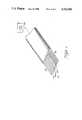
- FIG. 3is a pictorial, sectional view of lighting apparatus according to the present invention.
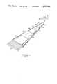
- FIG. 4is a sectional view of an extruded assembly according to the present invention.
- FIGS. 5a and 5bare, respectively, top and end views of a light source according to the present invention.
- FIG. 6is a pictorial view of another embodiment of the lighting apparatus according to the present invention.
- FIG. 7is a pictorial view of another embodiment of the lighting apparatus according to the present invention.
- the light-transmissive core 9may be glass, or plastic, or other optical transmitting materials with high index of refraction and with a surface- cladding coating 15 of different index of refraction.
- Optical fibersare commonly configured in this manner in small core diameters 14 of the order of 3 to 100 microns to assure substantial propagation of light flux in lower order modes from one end to another with only negligible losses through the surface cladding.
- conventional fibersas illustrated in the sectional view of FIG. 2, commonly are coated with a material 16 such as silicon dioxide or TEFLON-brand plastic material to assure that incident light flux at one end of the fiber propagates therethrough in lower order and fundamental modes to emerge substantially undiminished or unaffected from the other end.
- the fibers of the present inventionare formed in a manner which supports higher order modes and resulting lateral emission of light from the surface of the fiber along the length thereof.
- the diameter of the fiber core 9is typically of the order of 400 to 1000 microns in diameter, or several times the diameter of conventional fiber cores. Larger diameter cores 9 are desirable for supporting higher order modes of propagation of light flux in the core by way of multiple reflections of light from the microetched boundary 13 of the core material 9 and the transparent clad material 15 of different index of refraction.
- the diameter of the fiber core 9suitably, the angle of incidence of light upon the boundary 13 approaches the critical angle at which substantially all the incident light emerges through the clad material 15, and little reflects internally within the core material 9.
- the boundary 13may include surface irregularities on the fiber core 9 to enhance lateral emission of light flux.
- the surface of the fiber core 9may have a surface roughness of approximately 0.3 micron anomalies which can be provided in many ways.
- the fiber core 9 of glass materialmay be chemically etched with hydrofluroic acid, or plastic fiber cores 9 may be roughened with about #600 grit-size abrasive, or the surface of the die through which the fiber core 9 is extruded may be roughened in order to form a roughened surface at the boundary 13.
- the surface anomalies on fiber core 9may be radially or longitudinally oriented, or both.
- the fiber core 9may also include light-scattering centers 17 disposed within the core to enhance the higher-order modes of propagation along the core, and thereby to enhance lateral emission of light through the clad material 15.
- the scattering centers 17may be centrally oriented within the core material 9 along the length thereof to intercept and reflect or diffuse light flux 19 that is substantially aligned with the central axis 21 of the core material 9.
- These scattering centers 17may be formed of transparent material such as glass or plastic having an index of refraction that is different from the index of refraction of the core material 9.
- the scattering centers 17may be of translucent or opaque material such as vitrified glass or glass particles, or the like, which serve as light diffusion centers.
- the change of index of refraction at scattering centersis accomplished by forming minute bubbles within the core material 9 at selected intervals in the central region of the core material along its length.
- scattering centersmay be dispersed throughout the cross section and length of the core material 9 to diffuse or reflect light flux that is propagating in lower order modes into light flux having lateral component for emission through the clad material 15.
- light scattering centers 17 of any of the types described abovemay be distributed along the fiber with density (i.e., number or size of scattering centers per unit length) that increases with distance from an end in order to provide substantially uniform light flux density emitted through the clad material 15 over the length of the fiber.
- light flux from a light source 20may be coupled to each end of a fiber to enhance total light flux emitted laterally from the fiber over the entire length thereof between lights sources at the ends.
- a single light sourcemay be coupled to both ends of the optical channels to form a loop lighting configuration.
- the light scattering centers 17may be distributed with density that increases with distance from each end to produce a maximum density of scattering centers at a location intermediate the ends thereof. Fibers of this type may therefore be illuminated from both ends to emit light laterally and with substantially uniform intensity over the length thereof between light sources.
- An extrusion 23 of glass or plastic transparent materialincludes a longitudinal channel 22 intermediate a lens region 25 and underside reflector region 27 for supporting therein a plurality of optical fibers 26 of the type described above, positioned substantially in side-by-side relationship across the width of the channel 22.
- the lens region 25may have a double convex cross-sectional shape along the length of the extrusion 23 or a single convex, as shown, or other desirable lens shape above the fibers 26.
- the optical fibers 26are disposed above the reflector region 27 which may include a "mirrored" or white surface 29 for improved spectral reflections of light that emerges laterally from the optical fibers 26.
- the extrusion 23may include one or more support channels 31 along the opposite sides for interlocking engagement with support rails 33 along the length of the extrusion.
- the entire assembly including lens region 25, reflector region 27 and support rails 33may constitute a single extrusion for incorporation around the optical fibers 26 that form the light-transmission channel.
- the light-transmission channelmay be formed as a flat ribbon "fiber" instead of by a plurality of side-by-side cylindrical fibers disposed in a substantial ribbon-like configuration.
- Suitable materials for the extrusion 33include glass for the lens and reflector regions 25,27 to completely encase the optical fibers 26, or plastic materials such as polyvinylchloride, polystyrene, or polymethamethacrylate for the lens and reflector regions 25,27 and side rails 33.
- FIG. 4there is shown a sectional view of another extruded assembly including the oval- or elliptical-shaped casing 35 surrounding the optical fibers 37, and a support element 39 which may be continuously disposed along the casing 35 or disposed only at selected intervals therealong.
- the optical fibers 37 contained within the casingare disposed to emit light laterally through the casing, the shape of which thus forms a lens-like structure.
- the casing 35may be extruded of such materials as glass or plastic to completely encase the fibers 37, or a lengthwise slit 41 may be provided on the underside of the casing (extruded of resilient plastic material) to facilitate assembly of the casing 35 around the optical fibers 37.
- the support element 39may be extruded of resilient plastic material, and may have a "mirrored" or white surface on the inner, central surfaces 43 thereof to improve the spectral and diffusive optical properties thereof, for the reasons previously described.
- the walls 45 of the casing 35 in the inner or lower sectionmay include "mirrored” or white surfaces, while the walls 46 in the outer or upper section remain transparent to improve the light emission efficiency of the assembly for light flux that emanates laterally from the optical fibers 37.
- Suitable materials for the casing 35include glass, or plastics such as polyvinylchloride, polystyrene, and polymethamethacrylate for flexible and inexpensive casings.
- the light apparatusis ideally suited for operation within potentially hazardous environments such as in or near water in swimming pools, ships, or outdoor walkways, and the like, where the prospects of electrical shock can be completely eliminated, and the presence of water or moisture is not detrimental to the apparatus.
- the present lighting apparatusis well suited for hallway illumination in lengthy strips.
- the light source or sources for illuminating one or both ends of the optical fibersmay be disposed within protected areas such as within airshafts, and the optical channel may be mounted along the ceiling or lower at baseboard level along the hallways as reliable guideways toward exits for use in cases of dense smoke which may obliterate clear vision of conventional exit signs.
- the lighting apparatus of the present inventionmay be used within the passenger compartments of airplanes and in other such applications requiring high levels of reliability and immunity from hazardous operation to designate walkways, exit doors, and the like.
- the fiber optic bundles and encasements according to the present inventionare readily able to conform to curves and corners, and penetrate walls and bulkheads when being installed in great lengths at distances away from the light source or sources at one or both ends of the light channel.
- FIGS. 5a and 5bthere are shown top and end views, respectively, of a light source and housing for illuminating the optical fibers in a manner suitable for enhancing the higher-order modes of light flux within the optical fibers.
- a light source and housingmay be attached to the optical channel 22 of an assembly at one end, or at both ends, thereof to provide ample light flux within the optical fibers for substantially uniform lateral emission from the fibers over the length thereof.
- the housing 47includes a light bulb and reflector system 49 for focussing light 50 through a color wheel 52 onto the input end of a beam splitter 54 of conventional design.
- the dual-port channel 54provides two output ports 56, 58 to which the optical fibers of the present lighting apparatus may be attached.
- the two output ports 56, 58provide basis for illuminating both ends a given optical fiber light channel (in loop configuration), or for illuminating single ends of separate optical fiber light channels (in continuous configuration).
- the color wheel 52includes a plurality of perimeter sectors 60 of different color, transparent light filters mounted for rotation on the shaft 62 of drive motor 64.
- the motor 64 and the light bulb of hte system 49may be operated on the low-voltage output of transformer 66.
- Switches 68,69are wired in circuit with the motor 64 and light bulb to control the output of light at a selected color or wavelength, or at continuously-changing colors, as deisired.
- a light source or sources at one or both ends of the optical channelmay emit ⁇ white ⁇ light or may emit radiation at selected wavelengths within the range from infrared to ultraviolet (all referred to herein as "radiation").
- radiationinfrared to ultraviolet
- such light sourcesmay be operated at different wavelengths of radiation to provide color gradations with distance from a light source.
- the color gradations of light emitted laterally from the channelvary from substantially one primary color near one source, to the resultant color of two primary colors in the central region of the channel between sources, to substantially the other primary color near the other light source at the opposite end of the optical channel.
- the optical channelmay be formed of plastic material such as polymethamethacrylate, or the like, and be embedded with ultraviolet-sensitive or other actinically-sensitive dyes such as fluorene that respond differently to ultraviolet light at selected locations along the length of the channel.
- the light source or sources 28 at one or both ends of the channelmay illuminate the optical channel 26 with ultraviolet light which then stimulates emission of radiation by the embedded dyes at various color wavelengths along the length of the optical channel 26.
- Similar operating characteristicsmay be achieved using optical channels of different colored material to serve as color filters which enhance emission of light of different colors from the surface of the optical channel.
- the color of the material forming the optical channelmay vary with length along a particular fiber 30, or may vary from fiber to fiber 32, or may vary in a combination of the above characteristics, as illustrated in FIG. 6, to provide light that emanates from the optical channel over the length thereof that varies in color over the entire visible spectrum with length or width, or both, of the optical channel 26.
- FIG. 7there is shown a pictorial view of another embodiment of the present invention in which transparent windows 51 are disposed at selected intervals along the optical channel 53 between opaque or less transmissive regions 55.
- the interior surfaces of the opaque regions 55may include "mirrored" or white surfaces to efficiently reflect light from the light source 28 that is laterally-emitted from the optical channel in such regions back into the optical channel to preserve the total light flux available within the channel for lateral emission only through the window regions 51 at the selected locations.
- Lenses 57for example, of cylindrical cross-section may be disposed over the window regions 51 to enhance the directionality of light emanating from the window regions 51. Lighting apparatus of this type is well suited for use as decorative lighting where each window region 51 may include different color filters.
- the lighting apparatus and method of the present inventionprovides lighting for hazardous and decorative applications using optical fibers which are formed to enhance lateral emission of light from the fibers, and which can be illuminated from both ends to enhance luminous intensity of emitted light. Additionally, the lighting apparatus and method of the present invention is suitable for illuminating hallways and exit passages in public structures with a high degree of immunity from adverse effects of fire and smoke, which immunity is attributable to the light source or sources being mounted in a protected location. Decorative color effects are made possible by using selected combinations of colored fiber optic materials, actinically-sensitive dyes, and light sources of different colors.
Landscapes
- Physics & Mathematics (AREA)
- General Physics & Mathematics (AREA)
- Optics & Photonics (AREA)
- Light Guides In General And Applications Therefor (AREA)
- Non-Portable Lighting Devices Or Systems Thereof (AREA)
- Planar Illumination Modules (AREA)
- Optical Fibers, Optical Fiber Cores, And Optical Fiber Bundles (AREA)
Abstract
Description
Claims (5)
Priority Applications (9)
| Application Number | Priority Date | Filing Date | Title |
|---|---|---|---|
| US07/000,113US4763984A (en) | 1987-01-02 | 1987-01-02 | Lighting apparatus and method |
| EP87118769AEP0273311A3 (en) | 1987-01-02 | 1987-12-17 | Lighting apparatus and method |
| AU82802/87AAU598079B2 (en) | 1987-01-02 | 1987-12-18 | Lighting apparatus and method |
| MX009924AMX165770B (en) | 1987-01-02 | 1987-12-24 | LIGHTING APPARATUS AND METHOD |
| JP62329404AJPS63247705A (en) | 1987-01-02 | 1987-12-25 | Light apparatus and method |
| BR8707240ABR8707240A (en) | 1987-01-02 | 1987-12-30 | LIGHTING EQUIPMENT AND METHOD OF DISTRIBUTING RADIATION FROM A LIGHT SOURCE IN A RADIATION TRANSMISSION CHANNEL |
| CA000555648ACA1246038A (en) | 1987-01-02 | 1987-12-30 | Lighting apparatus and method |
| KR1019870015757AKR910007347B1 (en) | 1987-01-02 | 1987-12-31 | Lighting device and method |
| CN88100217ACN1007452B (en) | 1987-01-02 | 1988-01-02 | Lighting device and method |
Applications Claiming Priority (1)
| Application Number | Priority Date | Filing Date | Title |
|---|---|---|---|
| US07/000,113US4763984A (en) | 1987-01-02 | 1987-01-02 | Lighting apparatus and method |
Publications (1)
| Publication Number | Publication Date |
|---|---|
| US4763984Atrue US4763984A (en) | 1988-08-16 |
Family
ID=21689971
Family Applications (1)
| Application Number | Title | Priority Date | Filing Date |
|---|---|---|---|
| US07/000,113Expired - LifetimeUS4763984A (en) | 1987-01-02 | 1987-01-02 | Lighting apparatus and method |
Country Status (9)
| Country | Link |
|---|---|
| US (1) | US4763984A (en) |
| EP (1) | EP0273311A3 (en) |
| JP (1) | JPS63247705A (en) |
| KR (1) | KR910007347B1 (en) |
| CN (1) | CN1007452B (en) |
| AU (1) | AU598079B2 (en) |
| BR (1) | BR8707240A (en) |
| CA (1) | CA1246038A (en) |
| MX (1) | MX165770B (en) |
Cited By (58)
| Publication number | Priority date | Publication date | Assignee | Title |
|---|---|---|---|---|
| US4912605A (en)* | 1988-09-21 | 1990-03-27 | Tir Systems Ltd. | Illumination system which reduces loss of visibility caused by lamp failure |
| US4947293A (en)* | 1989-03-03 | 1990-08-07 | Johnson Glenn M | Cargo vehicle perimeter clearance lighting system |
| US5005108A (en)* | 1989-02-10 | 1991-04-02 | Lumitex, Inc. | Thin panel illuminator |
| US5009483A (en)* | 1989-04-12 | 1991-04-23 | Rockwell Iii Marshall A | Optical waveguide display system |
| US5016956A (en)* | 1989-10-02 | 1991-05-21 | Motorola, Inc. | Lighting panel for liquid crystal display |
| US5042892A (en)* | 1990-08-03 | 1991-08-27 | David Chiu | Fiber optic light panel |
| US5097396A (en)* | 1990-09-25 | 1992-03-17 | Poly-Optical Products, Inc. | Fiber optic backlighting panel |
| DE9204063U1 (en)* | 1992-03-26 | 1993-04-15 | Buechner, Thomas, 8901 Deubach | Backlight |
| US5249105A (en)* | 1988-07-14 | 1993-09-28 | Aromac Co. Ltd. | Surface like light emitting ornamental device using optical fibers |
| US5295047A (en)* | 1992-04-06 | 1994-03-15 | Ford Motor Company | Line-of-light illuminating device |
| US5307245A (en)* | 1991-06-27 | 1994-04-26 | Poly-Optical Products, Inc. | Fiber optic backlighting panel and zig-zag process for making same |
| US5333228A (en)* | 1993-05-21 | 1994-07-26 | Super Vision International Inc. | Lateral illumination fiber optic cable device and method of manufacture |
| US5339223A (en)* | 1993-03-24 | 1994-08-16 | Ohmeda Inc. | Servocontrol for fiberoptic phototherapy pad |
| US5406641A (en)* | 1993-06-15 | 1995-04-11 | Rohm And Haas Company | Flexible light pipe, cured composite and processes for preparation thereof |
| US5485541A (en)* | 1993-06-15 | 1996-01-16 | Rohm And Haas Company | Cured composite, processes and composition |
| US5568964A (en)* | 1992-07-10 | 1996-10-29 | Lumitex, Inc. | Fiber optic light emitting panel assemblies and methods of making such panel assemblies |
| US5653519A (en)* | 1993-12-16 | 1997-08-05 | Glass Illuminations, Inc. | Fiber optics illuminator system |
| WO1998043121A1 (en)* | 1997-03-27 | 1998-10-01 | Lumenyte International Corporation | Linear light form with light diverting layer |
| US5838860A (en)* | 1993-05-21 | 1998-11-17 | Super Vision International, Inc. | Fiber optic light source apparatus and method |
| US5876107A (en)* | 1995-06-27 | 1999-03-02 | Lumitex, Inc. | Light emitting panel assemblies |
| USRE36157E (en)* | 1989-01-30 | 1999-03-23 | Lumenyte International Corp. | Methods of manufacture of improved linear optical conduits |
| US5894686A (en)* | 1993-11-04 | 1999-04-20 | Lumitex, Inc. | Light distribution/information display systems |
| US5953469A (en)* | 1996-10-29 | 1999-09-14 | Xeotron Corporation | Optical device utilizing optical waveguides and mechanical light-switches |
| US6160938A (en)* | 1999-04-15 | 2000-12-12 | Little, Jr.; William D. | Concentric lay stranding for optical fiber cable |
| WO2000079318A1 (en)* | 1999-06-22 | 2000-12-28 | Transmatic, Inc. | Light fixture including light pipe having contoured cross-section |
| EP0952414A3 (en)* | 1998-04-20 | 2001-01-03 | Zumtobel Staff GmbH | Lighting arrangement for refrigerating devices |
| US6179454B1 (en) | 1998-02-06 | 2001-01-30 | North American Lighting, Inc. | Illumination system for vehicle running boards and the area below the running board |
| US6282355B1 (en) | 1998-03-27 | 2001-08-28 | Lumenyte International Corporation | Linear light form with light diverting layer |
| US20030095398A1 (en)* | 1996-01-16 | 2003-05-22 | Parker Jeffery R. | Light emitting panel assemblies for use in automotive applications and the like |
| US20030123246A1 (en)* | 1995-06-27 | 2003-07-03 | Parker Jeffery R. | Light emitting panel assemblies |
| US6594417B1 (en) | 1999-01-14 | 2003-07-15 | Federal-Mogul World Wide, Inc. | Waveguide assembly for laterally-directed illumination in a vehicle lighting system |
| US20030169997A1 (en)* | 2002-03-06 | 2003-09-11 | Federal-Mogul World Wide, Inc. | Illuminating waveguide |
| WO2003081300A1 (en)* | 2002-03-16 | 2003-10-02 | Lumenyte International Corporation | Led acrylic conduit |
| US20050072032A1 (en)* | 1995-06-27 | 2005-04-07 | Mccollum Timothy A. | Light emitting panel assemblies |
| US20050122591A1 (en)* | 1999-02-23 | 2005-06-09 | Parker Jeffery R. | Light redirecting films and film systems |
| US6967448B2 (en)* | 1997-08-26 | 2005-11-22 | Color Kinetics, Incorporated | Methods and apparatus for controlling illumination |
| US7343191B1 (en) | 2001-12-27 | 2008-03-11 | Fonar Corporation | MRI system |
| US7448775B2 (en) | 1999-02-23 | 2008-11-11 | Solid State Opto Limited | Transreflectors, transreflector systems and displays and methods of making transreflectors |
| US20100026703A1 (en)* | 2008-07-31 | 2010-02-04 | Parker Jeffery R | Optically transmissive substrates and light emitting assemblies and methods of making same, and methods of displaying images using the optically transmissive substrates and light emitting assemblies |
| US20100142226A1 (en)* | 2006-08-10 | 2010-06-10 | 3M Innovative Properties Company | Light guide for a lighting device |
| US8322905B2 (en) | 1999-02-23 | 2012-12-04 | Rambus International Ltd. | Edgelit panel with curvilinear light extracting deformities |
| US20160238784A1 (en)* | 2015-02-18 | 2016-08-18 | Corning Incorporated | Optical fiber illumination systems and methods |
| US9815501B2 (en) | 2014-10-21 | 2017-11-14 | Great Dane Llc | Cargo vehicle and molding assembly for a cargo vehicle |
| US10101553B2 (en) | 2015-05-20 | 2018-10-16 | Corning Optical Communications LLC | Traceable cable with side-emitting optical fiber and method of forming the same |
| US10101545B2 (en) | 2015-10-30 | 2018-10-16 | Corning Optical Communications LLC | Traceable cable assembly and connector |
| US10107983B2 (en) | 2016-04-29 | 2018-10-23 | Corning Optical Communications LLC | Preferential mode coupling for enhanced traceable patch cord performance |
| US10185111B2 (en) | 2016-04-08 | 2019-01-22 | Corning Optical Communications LLC | Traceable end point cable assembly |
| US10222561B2 (en) | 2016-12-21 | 2019-03-05 | Corning Research & Development Corporation | Light launch device for transmitting light into a traceable fiber optic cable assembly with tracing optical fibers |
| US10228526B2 (en) | 2015-03-31 | 2019-03-12 | Corning Optical Communications LLC | Traceable cable with side-emitting optical fiber and method of forming the same |
| US10234614B2 (en) | 2017-01-20 | 2019-03-19 | Corning Research & Development Corporation | Light source assemblies and systems and methods with mode homogenization |
| US10338317B2 (en) | 2015-07-17 | 2019-07-02 | Corning Optical Communications LLC | Systems and methods for traceable cables |
| US10379309B2 (en) | 2014-11-18 | 2019-08-13 | Corning Optical Communications LLC | Traceable optical fiber cable and filtered viewing device for enhanced traceability |
| US10534135B2 (en) | 2015-07-17 | 2020-01-14 | Corning Optical Communications LLC | Systems and methods for tracing cables and cables for such systems and methods |
| US10539747B2 (en) | 2017-12-05 | 2020-01-21 | Corning Research & Development Corporation | Bend induced light scattering fiber and cable assemblies and method of making |
| US10539758B2 (en) | 2017-12-05 | 2020-01-21 | Corning Research & Development Corporation | Traceable fiber optic cable assembly with indication of polarity |
| CN112444910A (en)* | 2019-09-04 | 2021-03-05 | 肖特股份有限公司 | Side-emitting optical waveguide and method for producing the same |
| US11579351B2 (en) | 2019-09-04 | 2023-02-14 | Schott Ag | Side-emitting light guide and method for the production thereof |
| EP3638984B1 (en)* | 2017-06-14 | 2023-12-20 | Brochier Technologies | Detection system for generating an electrical signal representing a variation of a light intensity and pressure sensor including such a detection system |
Families Citing this family (8)
| Publication number | Priority date | Publication date | Assignee | Title |
|---|---|---|---|---|
| FR2649842B1 (en)* | 1989-07-17 | 1994-04-08 | Alcatel Cit | ACCESS NETWORK FOR WIRELESS TELEPHONY SERVICE |
| AU4380199A (en)* | 1998-06-19 | 2000-01-05 | Laser Support Services Limited | Illumination system |
| US6519401B1 (en) | 1998-10-28 | 2003-02-11 | 3M Innovative Properties Company | Light fibers and methods for producing the same |
| US6398778B1 (en) | 1999-06-18 | 2002-06-04 | Photonics Research Ontario | Optical fiber diffuser |
| CA2375267A1 (en)* | 1999-06-18 | 2000-12-28 | Xijia Gu | Optical fiber diffuser |
| JP6228110B2 (en)* | 2011-04-28 | 2017-11-08 | エル イー エス エス・リミテッド | Waveguide device for illumination system |
| WO2013055841A1 (en)* | 2011-10-11 | 2013-04-18 | Corning Incorporated | Color illumination display panel comprising light diffusing fiber |
| RU2012101478A (en)* | 2012-01-17 | 2013-07-27 | Владимир Витальевич Мирошниченко | LIGHTED DEVICE HOUSING |
Citations (25)
| Publication number | Priority date | Publication date | Assignee | Title |
|---|---|---|---|---|
| US2058900A (en)* | 1935-09-25 | 1936-10-27 | Colin G Mcdonald | Sign |
| US2173371A (en)* | 1939-05-06 | 1939-09-19 | Penoyer James | Illuminated sign |
| US3038271A (en)* | 1959-07-22 | 1962-06-12 | United States Radium Corp | Self-luminous signs |
| US3208174A (en)* | 1962-04-05 | 1965-09-28 | Charles M Wrenshall | Illumination devices |
| US3382353A (en)* | 1966-11-30 | 1968-05-07 | American Cystoscope Makers Inc | Fiber optic light source |
| US3389247A (en)* | 1964-07-01 | 1968-06-18 | Fay E. Null | Pendulum light source |
| US3441957A (en)* | 1966-10-27 | 1969-04-29 | Jerome Friedman | Swimming pool and underwater lighting system |
| US3497981A (en)* | 1967-12-13 | 1970-03-03 | George Henry Tyne | Sign formed of light conducting and emitting members |
| US3536908A (en)* | 1968-04-08 | 1970-10-27 | Nat Statham Inc | Fiber optic lighting system |
| US3733481A (en)* | 1970-06-11 | 1973-05-15 | Bausch & Lomb | Fiber optics light source |
| US3775606A (en)* | 1972-01-07 | 1973-11-27 | Medical Prod Corp | Fiber-optic light console |
| US3813514A (en)* | 1972-10-16 | 1974-05-28 | J Canty | Light piping unit for supplying radiant energy to the interior of a pressure vessel |
| US4025779A (en)* | 1975-04-28 | 1977-05-24 | Ahroni Joseph M | Optic fiber decorative device |
| US4128332A (en)* | 1975-03-24 | 1978-12-05 | Xerox Corporation | Illuminator |
| US4236191A (en)* | 1978-01-26 | 1980-11-25 | Martinez Fredy R | Illuminated musical instrument |
| JPS57207204A (en)* | 1981-06-17 | 1982-12-18 | Furukawa Electric Co Ltd:The | Optical fiber |
| US4422719A (en)* | 1981-05-07 | 1983-12-27 | Space-Lyte International, Inc. | Optical distribution system including light guide |
| US4425599A (en)* | 1981-06-05 | 1984-01-10 | Volpi Ag | Cavity illuminating device |
| US4425907A (en)* | 1980-09-25 | 1984-01-17 | Exxon Research And Engineering Co. | Reflector-coupled fluorescent solar collector |
| US4454568A (en)* | 1982-03-15 | 1984-06-12 | Interactive Entertainment Corp. | Light pattern generator |
| US4466697A (en)* | 1981-11-12 | 1984-08-21 | Maurice Daniel | Light dispersive optical lightpipes and method of making the same |
| US4564261A (en)* | 1983-04-14 | 1986-01-14 | Hitachi, Ltd. | Bundle of optical fibers |
| US4569334A (en)* | 1981-05-22 | 1986-02-11 | Fuji Photo Optical Co., Ltd. | Apparatus for restoring the light transmittance of an image-transmitting optical fiber bundle used in a fiber optic endoscope |
| WO1986005858A1 (en)* | 1985-03-27 | 1986-10-09 | Lumenyte Corporation | High-intensity light source for a fiber optics illumination system |
| US4637686A (en)* | 1983-04-08 | 1987-01-20 | Kokusai Denshin Denwa Co., Ltd. | Optical fiber with light reflecting particles dispersed through buffer layers to dissipate leaky cladding modes |
Family Cites Families (6)
| Publication number | Priority date | Publication date | Assignee | Title |
|---|---|---|---|---|
| US3718814A (en)* | 1972-03-27 | 1973-02-27 | Gen Motors Corp | Fiber optic illuminator and method of making same |
| US4389085A (en)* | 1978-02-22 | 1983-06-21 | Kei Mori | Lighting system utilizing the sunlight |
| JPS58208708A (en)* | 1982-05-28 | 1983-12-05 | Hitachi Cable Ltd | leaky optical fiber |
| DE3423895A1 (en)* | 1984-06-28 | 1986-01-09 | Thera Gesellschaft für Patentverwertung mbH, 8036 Herrsching | RADIATION DEVICE |
| US4561043A (en)* | 1984-09-27 | 1985-12-24 | Thompson Gary J | Decorative light display |
| JPS61275803A (en)* | 1985-05-31 | 1986-12-05 | Mitsubishi Rayon Co Ltd | optical fiber |
- 1987
- 1987-01-02USUS07/000,113patent/US4763984A/ennot_activeExpired - Lifetime
- 1987-12-17EPEP87118769Apatent/EP0273311A3/ennot_activeCeased
- 1987-12-18AUAU82802/87Apatent/AU598079B2/ennot_activeCeased
- 1987-12-24MXMX009924Apatent/MX165770B/enunknown
- 1987-12-25JPJP62329404Apatent/JPS63247705A/enactivePending
- 1987-12-30CACA000555648Apatent/CA1246038A/ennot_activeExpired
- 1987-12-30BRBR8707240Apatent/BR8707240A/enunknown
- 1987-12-31KRKR1019870015757Apatent/KR910007347B1/ennot_activeExpired
- 1988
- 1988-01-02CNCN88100217Apatent/CN1007452B/ennot_activeExpired
Patent Citations (25)
| Publication number | Priority date | Publication date | Assignee | Title |
|---|---|---|---|---|
| US2058900A (en)* | 1935-09-25 | 1936-10-27 | Colin G Mcdonald | Sign |
| US2173371A (en)* | 1939-05-06 | 1939-09-19 | Penoyer James | Illuminated sign |
| US3038271A (en)* | 1959-07-22 | 1962-06-12 | United States Radium Corp | Self-luminous signs |
| US3208174A (en)* | 1962-04-05 | 1965-09-28 | Charles M Wrenshall | Illumination devices |
| US3389247A (en)* | 1964-07-01 | 1968-06-18 | Fay E. Null | Pendulum light source |
| US3441957A (en)* | 1966-10-27 | 1969-04-29 | Jerome Friedman | Swimming pool and underwater lighting system |
| US3382353A (en)* | 1966-11-30 | 1968-05-07 | American Cystoscope Makers Inc | Fiber optic light source |
| US3497981A (en)* | 1967-12-13 | 1970-03-03 | George Henry Tyne | Sign formed of light conducting and emitting members |
| US3536908A (en)* | 1968-04-08 | 1970-10-27 | Nat Statham Inc | Fiber optic lighting system |
| US3733481A (en)* | 1970-06-11 | 1973-05-15 | Bausch & Lomb | Fiber optics light source |
| US3775606A (en)* | 1972-01-07 | 1973-11-27 | Medical Prod Corp | Fiber-optic light console |
| US3813514A (en)* | 1972-10-16 | 1974-05-28 | J Canty | Light piping unit for supplying radiant energy to the interior of a pressure vessel |
| US4128332A (en)* | 1975-03-24 | 1978-12-05 | Xerox Corporation | Illuminator |
| US4025779A (en)* | 1975-04-28 | 1977-05-24 | Ahroni Joseph M | Optic fiber decorative device |
| US4236191A (en)* | 1978-01-26 | 1980-11-25 | Martinez Fredy R | Illuminated musical instrument |
| US4425907A (en)* | 1980-09-25 | 1984-01-17 | Exxon Research And Engineering Co. | Reflector-coupled fluorescent solar collector |
| US4422719A (en)* | 1981-05-07 | 1983-12-27 | Space-Lyte International, Inc. | Optical distribution system including light guide |
| US4569334A (en)* | 1981-05-22 | 1986-02-11 | Fuji Photo Optical Co., Ltd. | Apparatus for restoring the light transmittance of an image-transmitting optical fiber bundle used in a fiber optic endoscope |
| US4425599A (en)* | 1981-06-05 | 1984-01-10 | Volpi Ag | Cavity illuminating device |
| JPS57207204A (en)* | 1981-06-17 | 1982-12-18 | Furukawa Electric Co Ltd:The | Optical fiber |
| US4466697A (en)* | 1981-11-12 | 1984-08-21 | Maurice Daniel | Light dispersive optical lightpipes and method of making the same |
| US4454568A (en)* | 1982-03-15 | 1984-06-12 | Interactive Entertainment Corp. | Light pattern generator |
| US4637686A (en)* | 1983-04-08 | 1987-01-20 | Kokusai Denshin Denwa Co., Ltd. | Optical fiber with light reflecting particles dispersed through buffer layers to dissipate leaky cladding modes |
| US4564261A (en)* | 1983-04-14 | 1986-01-14 | Hitachi, Ltd. | Bundle of optical fibers |
| WO1986005858A1 (en)* | 1985-03-27 | 1986-10-09 | Lumenyte Corporation | High-intensity light source for a fiber optics illumination system |
Cited By (148)
| Publication number | Priority date | Publication date | Assignee | Title |
|---|---|---|---|---|
| US5249105A (en)* | 1988-07-14 | 1993-09-28 | Aromac Co. Ltd. | Surface like light emitting ornamental device using optical fibers |
| US4912605A (en)* | 1988-09-21 | 1990-03-27 | Tir Systems Ltd. | Illumination system which reduces loss of visibility caused by lamp failure |
| USRE36157E (en)* | 1989-01-30 | 1999-03-23 | Lumenyte International Corp. | Methods of manufacture of improved linear optical conduits |
| US5005108A (en)* | 1989-02-10 | 1991-04-02 | Lumitex, Inc. | Thin panel illuminator |
| US4947293A (en)* | 1989-03-03 | 1990-08-07 | Johnson Glenn M | Cargo vehicle perimeter clearance lighting system |
| US5009483A (en)* | 1989-04-12 | 1991-04-23 | Rockwell Iii Marshall A | Optical waveguide display system |
| US5016956A (en)* | 1989-10-02 | 1991-05-21 | Motorola, Inc. | Lighting panel for liquid crystal display |
| US5042892A (en)* | 1990-08-03 | 1991-08-27 | David Chiu | Fiber optic light panel |
| US5097396A (en)* | 1990-09-25 | 1992-03-17 | Poly-Optical Products, Inc. | Fiber optic backlighting panel |
| US5307245A (en)* | 1991-06-27 | 1994-04-26 | Poly-Optical Products, Inc. | Fiber optic backlighting panel and zig-zag process for making same |
| DE9204063U1 (en)* | 1992-03-26 | 1993-04-15 | Buechner, Thomas, 8901 Deubach | Backlight |
| US5295047A (en)* | 1992-04-06 | 1994-03-15 | Ford Motor Company | Line-of-light illuminating device |
| US5568964A (en)* | 1992-07-10 | 1996-10-29 | Lumitex, Inc. | Fiber optic light emitting panel assemblies and methods of making such panel assemblies |
| US5339223A (en)* | 1993-03-24 | 1994-08-16 | Ohmeda Inc. | Servocontrol for fiberoptic phototherapy pad |
| US5333228A (en)* | 1993-05-21 | 1994-07-26 | Super Vision International Inc. | Lateral illumination fiber optic cable device and method of manufacture |
| WO1994028451A1 (en)* | 1993-05-21 | 1994-12-08 | Super Vision International, Inc. | Lateral illumination fiber optic cable device and method of manufacture |
| AU686172B2 (en)* | 1993-05-21 | 1998-02-05 | Nexxus Lighting, Inc. | Lateral illumination fiber optic cable device and method of manufacture |
| US5838860A (en)* | 1993-05-21 | 1998-11-17 | Super Vision International, Inc. | Fiber optic light source apparatus and method |
| US5406641A (en)* | 1993-06-15 | 1995-04-11 | Rohm And Haas Company | Flexible light pipe, cured composite and processes for preparation thereof |
| US5485541A (en)* | 1993-06-15 | 1996-01-16 | Rohm And Haas Company | Cured composite, processes and composition |
| US5894686A (en)* | 1993-11-04 | 1999-04-20 | Lumitex, Inc. | Light distribution/information display systems |
| US5653519A (en)* | 1993-12-16 | 1997-08-05 | Glass Illuminations, Inc. | Fiber optics illuminator system |
| US7178965B2 (en) | 1995-06-27 | 2007-02-20 | Solid State Opto Limited | Light emitting panel assemblies having LEDs of multiple colors |
| US8142063B2 (en) | 1995-06-27 | 2012-03-27 | Rambus International Ltd. | Light emitting panel assemblies |
| US8308334B2 (en) | 1995-06-27 | 2012-11-13 | Rambus International Ltd. | Light emitting panel assemblies |
| US5921652A (en)* | 1995-06-27 | 1999-07-13 | Lumitex, Inc. | Light emitting panel assemblies |
| US8215816B2 (en) | 1995-06-27 | 2012-07-10 | Rambus International Ltd. | Light emitting panel assemblies |
| US6079838A (en)* | 1995-06-27 | 2000-06-27 | Lumitex, Inc. | Light emitting panel assemblies |
| US5876107A (en)* | 1995-06-27 | 1999-03-02 | Lumitex, Inc. | Light emitting panel assemblies |
| US8123393B2 (en) | 1995-06-27 | 2012-02-28 | Rambus International Ltd. | Light emitting panel assemblies |
| US7963687B2 (en) | 1995-06-27 | 2011-06-21 | Rambus International Ltd. | Light emitting panel assemblies |
| US7798695B2 (en) | 1995-06-27 | 2010-09-21 | Rambus International Ltd. | Light emitting panel assemblies |
| US7780329B2 (en) | 1995-06-27 | 2010-08-24 | Rambus International Ltd. | Light emitting panel assemblies |
| US7736043B2 (en) | 1995-06-27 | 2010-06-15 | Rambus International Ltd. | Light emitting panel assemblies |
| US7703967B2 (en) | 1995-06-27 | 2010-04-27 | Rambus International Ltd. | Light emitting panel assemblies |
| US20090257244A1 (en)* | 1995-06-27 | 2009-10-15 | Parker Jeffery R | Light emitting panel assemblies |
| US20030123246A1 (en)* | 1995-06-27 | 2003-07-03 | Parker Jeffery R. | Light emitting panel assemblies |
| US20030123247A1 (en)* | 1995-06-27 | 2003-07-03 | Parker Jeffery R. | Light emitting panel assemblies |
| US20030123245A1 (en)* | 1995-06-27 | 2003-07-03 | Parker Jeffery R. | Light emitting panel assemblies |
| US20090207632A1 (en)* | 1995-06-27 | 2009-08-20 | Mccollum Timothy A | Light emitting panel assemblies |
| US7563012B2 (en) | 1995-06-27 | 2009-07-21 | Solid State Opto Limited | Light emitting panel assemblies |
| US7537370B2 (en) | 1995-06-27 | 2009-05-26 | Solid State Opto Limited | Light emitting panel assemblies |
| US7524101B2 (en) | 1995-06-27 | 2009-04-28 | Solid State Opto Limited | Light emitting panel assemblies |
| US20040012946A1 (en)* | 1995-06-27 | 2004-01-22 | Parker Jeffery R. | Light emitting panel assemblies |
| US20040080927A1 (en)* | 1995-06-27 | 2004-04-29 | Parker Jeffery R. | Light emitting panel assemblies |
| US6749312B2 (en) | 1995-06-27 | 2004-06-15 | Solid State Opto Limited | Light emitting panel assemblies |
| US20040165372A1 (en)* | 1995-06-27 | 2004-08-26 | Parker Jeffery R. | Light emitting panel assemblies |
| US20050007759A1 (en)* | 1995-06-27 | 2005-01-13 | Parker Jeffery R. | Light emitting panel assemblies |
| US20050072032A1 (en)* | 1995-06-27 | 2005-04-07 | Mccollum Timothy A. | Light emitting panel assemblies |
| US7513672B2 (en) | 1995-06-27 | 2009-04-07 | Solid State Opto Limited | Light emitting panel assemblies |
| US20050094418A1 (en)* | 1995-06-27 | 2005-05-05 | Parker Jeffery R. | Light emitting panel assemblies |
| US20050111238A1 (en)* | 1995-06-27 | 2005-05-26 | Parker Jeffery R. | Light emitting panel assemblies |
| US20050111241A1 (en)* | 1995-06-27 | 2005-05-26 | Parker Jeffery R. | Light emitting panel assemblies |
| US7467887B2 (en) | 1995-06-27 | 2008-12-23 | Solid State Opto Limited | Light emitting panel assemblies |
| US20080266899A1 (en)* | 1995-06-27 | 2008-10-30 | Parker Jeffery R | Light emitting panel assemblies |
| US20050207154A1 (en)* | 1995-06-27 | 2005-09-22 | Solid State Opto Limited | Light emitting panel assemblies |
| US20050207178A1 (en)* | 1995-06-27 | 2005-09-22 | Solid State Opto Limited | Light emitting panel assemblies |
| US20050213323A1 (en)* | 1995-06-27 | 2005-09-29 | Solid State Opto Limited | Light emitting panel assemblies |
| US20050213322A1 (en)* | 1995-06-27 | 2005-09-29 | Solid State Opto Limited | Light emitting panel assemblies |
| US20080259640A1 (en)* | 1995-06-27 | 2008-10-23 | Parker Jeffery R | Light emitting panel assemblies |
| US20060028841A1 (en)* | 1995-06-27 | 2006-02-09 | Solid State Opto Limited | Light emitting panel assemblies |
| US20060028844A1 (en)* | 1995-06-27 | 2006-02-09 | Solid State Opto Limited | Light emitting panel assemblies |
| US20060028843A1 (en)* | 1995-06-27 | 2006-02-09 | Solid State Opto Limited | Light emitting panel assemblies |
| US20060028840A1 (en)* | 1995-06-27 | 2006-02-09 | Solid State Opto Limited | Light emitting panel assemblies |
| US20060028817A1 (en)* | 1995-06-27 | 2006-02-09 | Solid State Opto Limited | Light emitting panel assemblies |
| US7004611B2 (en) | 1995-06-27 | 2006-02-28 | Solid State Opto Limited | Light emitting panel assemblies |
| US20060158906A1 (en)* | 1995-06-27 | 2006-07-20 | Solid State Opto Limited | Light emitting panel assemblies |
| US7108414B2 (en)* | 1995-06-27 | 2006-09-19 | Solid State Opto Limited | Light emitting panel assemblies |
| US20060232965A1 (en)* | 1995-06-27 | 2006-10-19 | Solid State Opto Limited | Light emitting panel assemblies |
| US20060262567A1 (en)* | 1995-06-27 | 2006-11-23 | Solid State Opto Limited | Light emitting panel assemblies |
| US20060274554A1 (en)* | 1995-06-27 | 2006-12-07 | Solid State Opto Limited | Light emitting panel assemblies |
| US20060274555A1 (en)* | 1995-06-27 | 2006-12-07 | Solid State Opto Limited | Light emitting panel assemblies |
| US7160015B2 (en) | 1995-06-27 | 2007-01-09 | Solid State Opto Limited | Light emitting panel assemblies |
| US7165873B2 (en) | 1995-06-27 | 2007-01-23 | Solid State Opto Limited | Light emitting panel assemblies |
| US20080259642A1 (en)* | 1995-06-27 | 2008-10-23 | Parker Jeffery R | Light emitting panel assemblies |
| US7195389B2 (en) | 1995-06-27 | 2007-03-27 | Solid State Opto Limited | Light emitting panel assemblies |
| US20070103933A1 (en)* | 1995-06-27 | 2007-05-10 | Solid State Opto Limited | Light emitting panel assemblies |
| US7226196B2 (en) | 1995-06-27 | 2007-06-05 | Solid State Opto Limited | Light emitting panel assemblies |
| US20070133224A1 (en)* | 1995-06-27 | 2007-06-14 | Parker Jeffery R | Light emitting panel assemblies |
| US20070147087A1 (en)* | 1995-06-27 | 2007-06-28 | Parker Jeffery R | Light emitting panel assemblies |
| US20070153549A1 (en)* | 1995-06-27 | 2007-07-05 | Solid State Opto Limited | Light emitting panel assemblies |
| US7300194B2 (en) | 1995-06-27 | 2007-11-27 | Solid State Opto Limited | Light emitting panel assemblies |
| US7322730B2 (en) | 1995-06-27 | 2008-01-29 | Solid State Opto Limited | Light emitting panel assemblies |
| US7434973B2 (en) | 1995-06-27 | 2008-10-14 | Solid State Opto Limited | Light emitting panel assemblies |
| US7354184B2 (en) | 1995-06-27 | 2008-04-08 | Solid State Opto Limited | Light emitting panel assemblies |
| US7357553B2 (en) | 1995-06-27 | 2008-04-15 | Solid State Opto Limited | Light emitting panel assemblies |
| US7434974B2 (en) | 1995-06-27 | 2008-10-14 | Solid State Opto Limited | Light emitting panel assemblies |
| US7374305B2 (en) | 1995-06-27 | 2008-05-20 | Solid State Opto Limited | Light emitting panel assemblies |
| US7384177B2 (en) | 1995-06-27 | 2008-06-10 | Solid State Opto Limited | Light emitting panel assemblies |
| US7404660B2 (en) | 1995-06-27 | 2008-07-29 | Solid State Opto Limited | Light emitting panel assemblies |
| US7404661B2 (en) | 1995-06-27 | 2008-07-29 | Solid State Opto Limited | Light emitting panel assemblies |
| US20030095398A1 (en)* | 1996-01-16 | 2003-05-22 | Parker Jeffery R. | Light emitting panel assemblies for use in automotive applications and the like |
| US6886956B2 (en) | 1996-01-16 | 2005-05-03 | Solid State Opto Limited | Light emitting panel assemblies for use in automotive applications and the like |
| US5903695A (en)* | 1996-03-27 | 1999-05-11 | Lumenyte International Corp. | Linear light form with light diverting layer |
| US6650822B1 (en) | 1996-10-29 | 2003-11-18 | Xeotion Corp. | Optical device utilizing optical waveguides and mechanical light-switches |
| US5953469A (en)* | 1996-10-29 | 1999-09-14 | Xeotron Corporation | Optical device utilizing optical waveguides and mechanical light-switches |
| WO1998043121A1 (en)* | 1997-03-27 | 1998-10-01 | Lumenyte International Corporation | Linear light form with light diverting layer |
| AU727529B2 (en)* | 1997-03-27 | 2000-12-14 | Lumenyte International Corporation | Linear light form with light diverting layer |
| US6967448B2 (en)* | 1997-08-26 | 2005-11-22 | Color Kinetics, Incorporated | Methods and apparatus for controlling illumination |
| US6179454B1 (en) | 1998-02-06 | 2001-01-30 | North American Lighting, Inc. | Illumination system for vehicle running boards and the area below the running board |
| US6282355B1 (en) | 1998-03-27 | 2001-08-28 | Lumenyte International Corporation | Linear light form with light diverting layer |
| EP0952414A3 (en)* | 1998-04-20 | 2001-01-03 | Zumtobel Staff GmbH | Lighting arrangement for refrigerating devices |
| US6594417B1 (en) | 1999-01-14 | 2003-07-15 | Federal-Mogul World Wide, Inc. | Waveguide assembly for laterally-directed illumination in a vehicle lighting system |
| US8322905B2 (en) | 1999-02-23 | 2012-12-04 | Rambus International Ltd. | Edgelit panel with curvilinear light extracting deformities |
| US20050122591A1 (en)* | 1999-02-23 | 2005-06-09 | Parker Jeffery R. | Light redirecting films and film systems |
| US20080138024A1 (en)* | 1999-02-23 | 2008-06-12 | Parker Jeffery R | Light redirecting films and film systems |
| US7712932B2 (en) | 1999-02-23 | 2010-05-11 | Rambus International Ltd. | Light redirecting films having optical elements with curved surfaces |
| US7448775B2 (en) | 1999-02-23 | 2008-11-11 | Solid State Opto Limited | Transreflectors, transreflector systems and displays and methods of making transreflectors |
| US20100188858A1 (en)* | 1999-02-23 | 2010-07-29 | Parker Jeffery R | Light redirecting films and film systems |
| US8398274B2 (en) | 1999-02-23 | 2013-03-19 | Rambus International Ltd. | Light redirecting films including intersecting optical elements with flat and curved surfaces |
| US7364341B2 (en) | 1999-02-23 | 2008-04-29 | Solid State Opto Limited | Light redirecting films including non-interlockable optical elements |
| US6160938A (en)* | 1999-04-15 | 2000-12-12 | Little, Jr.; William D. | Concentric lay stranding for optical fiber cable |
| WO2000079318A1 (en)* | 1999-06-22 | 2000-12-28 | Transmatic, Inc. | Light fixture including light pipe having contoured cross-section |
| US20020025132A1 (en)* | 1999-09-27 | 2002-02-28 | Zarian James R. | Linear light form with light diverting layer |
| US7343191B1 (en) | 2001-12-27 | 2008-03-11 | Fonar Corporation | MRI system |
| US20030169997A1 (en)* | 2002-03-06 | 2003-09-11 | Federal-Mogul World Wide, Inc. | Illuminating waveguide |
| US6915062B2 (en) | 2002-03-06 | 2005-07-05 | Federal-Mogul World Wide, Inc. | Illuminating waveguide |
| WO2003081300A1 (en)* | 2002-03-16 | 2003-10-02 | Lumenyte International Corporation | Led acrylic conduit |
| US9625633B2 (en) | 2003-06-23 | 2017-04-18 | Rambus Delaware Llc | Light emitting panel assemblies |
| US9983340B2 (en) | 2003-06-23 | 2018-05-29 | Rambus Delaware Llc | Light emitting panel assemblies |
| US8104944B2 (en) | 2003-06-23 | 2012-01-31 | Rambus International Ltd. | Light emitting panel assemblies |
| US20100309685A1 (en)* | 2003-06-23 | 2010-12-09 | Mccollum Timothy A | Light emitting panel assemblies |
| US8459858B2 (en) | 2003-06-23 | 2013-06-11 | Rambus Delaware Llc | Light emitting panel assemblies |
| US8770814B2 (en) | 2003-06-23 | 2014-07-08 | Rambus Delaware Llc | Light emitting panel assemblies |
| US20100142226A1 (en)* | 2006-08-10 | 2010-06-10 | 3M Innovative Properties Company | Light guide for a lighting device |
| US8462292B2 (en) | 2008-07-31 | 2013-06-11 | Rambus Delaware Llc | Optically transmissive substrates and light emitting assemblies and methods of making same, and methods of displaying images using the optically transmissive substrates and light emitting assemblies |
| US20100026703A1 (en)* | 2008-07-31 | 2010-02-04 | Parker Jeffery R | Optically transmissive substrates and light emitting assemblies and methods of making same, and methods of displaying images using the optically transmissive substrates and light emitting assemblies |
| US9815501B2 (en) | 2014-10-21 | 2017-11-14 | Great Dane Llc | Cargo vehicle and molding assembly for a cargo vehicle |
| US10379309B2 (en) | 2014-11-18 | 2019-08-13 | Corning Optical Communications LLC | Traceable optical fiber cable and filtered viewing device for enhanced traceability |
| US20160238784A1 (en)* | 2015-02-18 | 2016-08-18 | Corning Incorporated | Optical fiber illumination systems and methods |
| US10101517B2 (en)* | 2015-02-18 | 2018-10-16 | Corning Incorporated | Optical fiber illumination systems and methods |
| US10228526B2 (en) | 2015-03-31 | 2019-03-12 | Corning Optical Communications LLC | Traceable cable with side-emitting optical fiber and method of forming the same |
| US10101553B2 (en) | 2015-05-20 | 2018-10-16 | Corning Optical Communications LLC | Traceable cable with side-emitting optical fiber and method of forming the same |
| US10338317B2 (en) | 2015-07-17 | 2019-07-02 | Corning Optical Communications LLC | Systems and methods for traceable cables |
| US10534135B2 (en) | 2015-07-17 | 2020-01-14 | Corning Optical Communications LLC | Systems and methods for tracing cables and cables for such systems and methods |
| US10101545B2 (en) | 2015-10-30 | 2018-10-16 | Corning Optical Communications LLC | Traceable cable assembly and connector |
| US10185111B2 (en) | 2016-04-08 | 2019-01-22 | Corning Optical Communications LLC | Traceable end point cable assembly |
| US10107983B2 (en) | 2016-04-29 | 2018-10-23 | Corning Optical Communications LLC | Preferential mode coupling for enhanced traceable patch cord performance |
| US10545298B2 (en) | 2016-12-21 | 2020-01-28 | Corning Research & Development Corporation | Traceable fiber optic cable assembly with illumination structure and tracing optical fibers for carrying light received from a light launch device |
| US10222560B2 (en) | 2016-12-21 | 2019-03-05 | Corning Research & Development Corporation | Traceable fiber optic cable assembly with fiber guide and tracing optical fibers for carrying light received from a light launch device |
| US10222561B2 (en) | 2016-12-21 | 2019-03-05 | Corning Research & Development Corporation | Light launch device for transmitting light into a traceable fiber optic cable assembly with tracing optical fibers |
| US10234614B2 (en) | 2017-01-20 | 2019-03-19 | Corning Research & Development Corporation | Light source assemblies and systems and methods with mode homogenization |
| EP3638984B1 (en)* | 2017-06-14 | 2023-12-20 | Brochier Technologies | Detection system for generating an electrical signal representing a variation of a light intensity and pressure sensor including such a detection system |
| US10539747B2 (en) | 2017-12-05 | 2020-01-21 | Corning Research & Development Corporation | Bend induced light scattering fiber and cable assemblies and method of making |
| US10539758B2 (en) | 2017-12-05 | 2020-01-21 | Corning Research & Development Corporation | Traceable fiber optic cable assembly with indication of polarity |
| CN112444910A (en)* | 2019-09-04 | 2021-03-05 | 肖特股份有限公司 | Side-emitting optical waveguide and method for producing the same |
| US11520096B2 (en)* | 2019-09-04 | 2022-12-06 | Schott Ag | Side-emitting light guide and method for the production thereof |
| US11579351B2 (en) | 2019-09-04 | 2023-02-14 | Schott Ag | Side-emitting light guide and method for the production thereof |
Also Published As
| Publication number | Publication date |
|---|---|
| JPS63247705A (en) | 1988-10-14 |
| AU8280287A (en) | 1988-07-21 |
| CN1007452B (en) | 1990-04-04 |
| EP0273311A3 (en) | 1989-10-25 |
| MX165770B (en) | 1992-12-03 |
| BR8707240A (en) | 1988-09-13 |
| CA1246038A (en) | 1988-12-06 |
| CN88100217A (en) | 1988-09-28 |
| KR880009236A (en) | 1988-09-14 |
| AU598079B2 (en) | 1990-06-14 |
| KR910007347B1 (en) | 1991-09-25 |
| EP0273311A2 (en) | 1988-07-06 |
Similar Documents
| Publication | Publication Date | Title |
|---|---|---|
| US4763984A (en) | Lighting apparatus and method | |
| US7186005B2 (en) | Color-changing illumination device | |
| US7008097B1 (en) | Illumination device for simulating neon or fluorescent lighting including a waveguide and a scattering cap | |
| CA1215957A (en) | Prism light guide luminaire | |
| EP1200772B1 (en) | Illumination apparatus | |
| EP1064570B1 (en) | Optical sheets suitable for spreading light | |
| CA2343281C (en) | Illumination system using edge-illuminated hollow waveguide and lenticular optical structures | |
| EP1521934B1 (en) | Illumination device for simulating neon lighting through use of fluorescent dyes | |
| US20050084229A1 (en) | Light insertion and dispersion system | |
| JP5608752B2 (en) | Light emitting device | |
| KR19990077328A (en) | Side emitting light conduit | |
| US20030198049A1 (en) | Illumination device for simulating neon lighting through use of fluorescent dyes | |
| EP1084366B1 (en) | Light distribution system | |
| JP2002519840A (en) | Structure to achieve linear light source geometry | |
| AU762579B2 (en) | Light with a light-guiding element | |
| US6928213B2 (en) | Directionally illuminating emergency system | |
| US11215338B2 (en) | Batwing diffusing lens luminaire | |
| WO2002021177A1 (en) | Optical conduit | |
| AU737722B2 (en) | A method for extracting and distributing light from solid transparent light guides | |
| US20070217189A1 (en) | Illumination Device | |
| JPH11353916A (en) | Information display device | |
| CA2282099A1 (en) | Optical lighting apparatus | |
| JP2002352603A (en) | Led lighting system | |
| JPH0772333A (en) | Pilot lamp | |
| JPH08273059A (en) | Device and method for displaying escape route |
Legal Events
| Date | Code | Title | Description |
|---|---|---|---|
| AS | Assignment | Owner name:FIBERSTARS, INC., 200 BROWN RD., SUITE 106, FREMON Free format text:ASSIGNMENT OF ASSIGNORS INTEREST.;ASSIGNORS:AWAI, GEORGE K.;ERNST, MICHAEL D.;REEL/FRAME:004655/0033 Effective date:19870102 Owner name:FIBERSTARS, INC., A CA. CORP.,CALIFORNIA Free format text:ASSIGNMENT OF ASSIGNORS INTEREST;ASSIGNORS:AWAI, GEORGE K.;ERNST, MICHAEL D.;REEL/FRAME:004655/0033 Effective date:19870102 | |
| STCF | Information on status: patent grant | Free format text:PATENTED CASE | |
| FPAY | Fee payment | Year of fee payment:4 | |
| FEPP | Fee payment procedure | Free format text:PAYOR NUMBER ASSIGNED (ORIGINAL EVENT CODE: ASPN); ENTITY STATUS OF PATENT OWNER: SMALL ENTITY | |
| REFU | Refund | Free format text:REFUND PROCESSED. MAINTENANCE FEE HAS ALREADY BEEN PAID (ORIGINAL EVENT CODE: R160); ENTITY STATUS OF PATENT OWNER: SMALL ENTITY | |
| FPAY | Fee payment | Year of fee payment:8 | |
| FPAY | Fee payment | Year of fee payment:12 | |
| AS | Assignment | Owner name:COMERICA BANK-CALIFORNIA, CALIFORNIA Free format text:SECURITY AGREEMENT;ASSIGNOR:FIBERSTARS, INC.;REEL/FRAME:012676/0047 Effective date:20011207 | |
| AS | Assignment | Owner name:FIBERSTARS, INC., CALIFORNIA Free format text:REASSIGNMENT AND RELEASE OF SECURITY INTEREST;ASSIGNOR:COMERICA BANK;REEL/FRAME:016489/0894 Effective date:20050830 | |
| AS | Assignment | Owner name:SILICON VALLEY BANK, CALIFORNIA Free format text:SECURITY AGREEMENT;ASSIGNOR:FIBERSTARS, INC.;REEL/FRAME:017164/0774 Effective date:20050815 | |
| AS | Assignment | Owner name:COMERICA BANK - CALIFORNIA, CALIFORNIA Free format text:RELEASE;ASSIGNOR:SILICON VALLEY BANK;REEL/FRAME:017314/0294 Effective date:20050815 | |
| AS | Assignment | Owner name:ENERGY FOCUS INC FKA FIBERSTARS, INC.,OHIO Free format text:RELEASE BY SECURED PARTY;ASSIGNOR:SILICON VALLEY BANK;REEL/FRAME:024128/0857 Effective date:20100323 | |
| AS | Assignment | Owner name:AUSTIN FINANCIAL SERVICES, INC., CALIFORNIA Free format text:SECURITY INTEREST;ASSIGNOR:ENERGY FOCUS, INC.;REEL/FRAME:048195/0381 Effective date:20181211 |