US4763655A - Frequency-controlled heart pacemaker - Google Patents
Frequency-controlled heart pacemakerDownload PDFInfo
- Publication number
- US4763655A US4763655AUS07/062,707US6270787AUS4763655AUS 4763655 AUS4763655 AUS 4763655AUS 6270787 AUS6270787 AUS 6270787AUS 4763655 AUS4763655 AUS 4763655A
- Authority
- US
- United States
- Prior art keywords
- signal corresponding
- blood
- blood oxygen
- temperature
- signal
- Prior art date
- Legal status (The legal status is an assumption and is not a legal conclusion. Google has not performed a legal analysis and makes no representation as to the accuracy of the status listed.)
- Expired - Lifetime
Links
Images

Classifications
- A—HUMAN NECESSITIES
- A61—MEDICAL OR VETERINARY SCIENCE; HYGIENE
- A61B—DIAGNOSIS; SURGERY; IDENTIFICATION
- A61B5/00—Measuring for diagnostic purposes; Identification of persons
- A61B5/145—Measuring characteristics of blood in vivo, e.g. gas concentration or pH-value ; Measuring characteristics of body fluids or tissues, e.g. interstitial fluid or cerebral tissue
- A61B5/1455—Measuring characteristics of blood in vivo, e.g. gas concentration or pH-value ; Measuring characteristics of body fluids or tissues, e.g. interstitial fluid or cerebral tissue using optical sensors, e.g. spectral photometrical oximeters
- A61B5/1459—Measuring characteristics of blood in vivo, e.g. gas concentration or pH-value ; Measuring characteristics of body fluids or tissues, e.g. interstitial fluid or cerebral tissue using optical sensors, e.g. spectral photometrical oximeters invasive, e.g. introduced into the body by a catheter
- A—HUMAN NECESSITIES
- A61—MEDICAL OR VETERINARY SCIENCE; HYGIENE
- A61N—ELECTROTHERAPY; MAGNETOTHERAPY; RADIATION THERAPY; ULTRASOUND THERAPY
- A61N1/00—Electrotherapy; Circuits therefor
- A61N1/18—Applying electric currents by contact electrodes
- A61N1/32—Applying electric currents by contact electrodes alternating or intermittent currents
- A61N1/36—Applying electric currents by contact electrodes alternating or intermittent currents for stimulation
- A61N1/362—Heart stimulators
- A61N1/365—Heart stimulators controlled by a physiological parameter, e.g. heart potential
- A61N1/36514—Heart stimulators controlled by a physiological parameter, e.g. heart potential controlled by a physiological quantity other than heart potential, e.g. blood pressure
- A61N1/3655—Heart stimulators controlled by a physiological parameter, e.g. heart potential controlled by a physiological quantity other than heart potential, e.g. blood pressure controlled by body or blood temperature
- A—HUMAN NECESSITIES
- A61—MEDICAL OR VETERINARY SCIENCE; HYGIENE
- A61N—ELECTROTHERAPY; MAGNETOTHERAPY; RADIATION THERAPY; ULTRASOUND THERAPY
- A61N1/00—Electrotherapy; Circuits therefor
- A61N1/18—Applying electric currents by contact electrodes
- A61N1/32—Applying electric currents by contact electrodes alternating or intermittent currents
- A61N1/36—Applying electric currents by contact electrodes alternating or intermittent currents for stimulation
- A61N1/362—Heart stimulators
- A61N1/365—Heart stimulators controlled by a physiological parameter, e.g. heart potential
- A61N1/36514—Heart stimulators controlled by a physiological parameter, e.g. heart potential controlled by a physiological quantity other than heart potential, e.g. blood pressure
- A61N1/36557—Heart stimulators controlled by a physiological parameter, e.g. heart potential controlled by a physiological quantity other than heart potential, e.g. blood pressure controlled by chemical substances in blood
Definitions
- the present inventionis directed to a frequency-controlled heart pacemaker, and in particular to a heart pacemaker wherein the stimulation frequency is controlled dependent on a measurement of the blood oxygen saturation of the patient.
- Controlling the stimulation frequency of a heart pacemaker based on a measurement of the blood oxygen saturation of the patientis known, for example, from German OS No. 34 22 913.
- a heart pacemakerhaving a blood oxygen sensor which generates a signal corresponding to the blood oxygen saturation of a patient, a temperature sensor which generates a signal dependent on the blood temperature of the patient, and means for combining the blood oxygen signal and the temperature signal such that the values of the blood oxygen signal are reduced in ranges of higher load, such load being indicated by the value of the temperature dependent signal.
- the combined signalis supplied to a frequency control unit for a pulse generator in the heart pacemaker, so that the stimulation frequency is controlled by the combined signal of oxygen saturation and temperature.
- the inventionmakes use of the fact that the temperature in venous blood increases when the body is under load. If both the temperature and the blood oxygen level of a patient are measured, and respective signals generated corresponding to the blood oxygen and to the temperature, the temperature signal will behave opposite to the blood oxygen signal.
- the blood oxygen signalwhich decreases under higher load, is decreased further in accordance with the principles of the present invention by combination with the temperature signal, which increases under higher load.
- a control signal for the frequency control unit of a heart pacemakeris thus obtained which is more exact than the control signal based solely on blood oxygen level in conventional frequency-controlled heart pacemakers.
- FIG. 1is a schematic block diagram of a frequency-controlled heart pacemaker constructed in accordance with the principles of the present invention.
- FIG. 2is a schematic block diagram of a further embodiment of a frequency-controlled heart pacemaker constructed in accordance with the principles of the present invention.
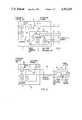
- FIG. 3is a circuit diagram of the blood oxygen/temperature measuring unit of the pacemaker of FIGS. 1 or 2.
- a frequency-controlled heart pacemaker constructed in accordance with the principles of the present inventionis generally referenced at 1 in FIG. 1.
- the pacemakerincludes a pulse generator 2 which generates stimulation pulses 3, which can be conducted to a stimulation electrode 5 via a stimulation catheter 4.
- the heart pacemaker 1has a passive electrode 6, which may be the conductive (for example, metallic) housing 7 of the heart pacemaker 1.
- the pacemaker 1also includes a frequency control unit 8 which sets a desired stimulation frequency at the pulse generator 2.
- the frequency control unit 8is inversely driven by the output signal S O .sbsb.2 T from a blood oxygen/temperature sensing unit 10.
- the signalis supplied to the frequency control unit 8 on a control line 9.
- An inverter 11is connected in the control line 9 between the frequency control unit 8 and the measuring unit 10.
- the stimulation frequency at the pulse generator 2will be decreased.
- the stimulation frequencyis correspondingly increased.
- the blood oxygen/temperature measuring unit 10includes a light transmitter 12 and a light receiver 13 for measuring the blood oxygen level of the patient.
- the light transmitter 12is connected via a line 14 to an amplifier 16, and the light receiver 13 is connected to the amplifier 16 via a line 15.
- the measuring unit 10further includes a temperature sensor 17 connected via a line 18 to an amplifier 19.
- the temperature sensor 17generates a temperature signal S T .
- the amplifier 19is followed by an inverter 20.
- the output signal (inverted temperature signal) of the inverter 20is supplied to a signal combining unit 21 together with the output signal (signal dependent on blood oxygen) of the amplifier 16.
- the inverted temperature signalis superimposed on the blood oxygen signal such that the blood oxygen is lowered in higher load ranges.
- the temperature signal S Thas a higher value in these ranges, and by inverting that signal in the inverter 20, the output of the inverter 20 has a lower value in those regions, which is used to decrease the blood oxygen signal in those ranges, such as by adding the inverted signal thereto.
- the stimulation catheter 4functions as the second supply line for the measuring unit 10.
- the measuring unit 10is connected to the line from the stimulation catheter 4 by a connecting line 22.
- a switch 23, arranged in the control line 9 between the measuring unit 10 and the inverter 11,is controlled by the output signal of the frequency control unit 8 via a line 24.
- the switch 23is closed between two successive stimulation pulses 3.
- a further switch 26is closed via the branch line 25, so that the stimulation electrode 5 is connected to ground via the stimulation catheter 4. Is is thereby assured that no test current can flow through the stimulation circuit.
- FIG. 2Another embodiment of a frequency-controlled heart pacemaker constructed in accordance with the principles of the present invention is shown in FIG. 2, the pacemaker being generally referenced at 28.
- the embodiment of FIG. 2differs from the embodiment of FIG. 1 in that the blood oxygen/temperature measuring unit 10 is disposed outside of the housing 7 of the heart pacemaker.
- the measuring unit 10is preferably disposed in the stimulation catheter a few centimeters behind the stimulation electrode 5.
- the stimulation catheteris a bipolar catheter, referenced at 29 and indicated with dashed lines in FIG. 2.
- the first lead of the bipolar catheter 29, to which the stimulation electrode 5 is connected,is referenced 30 in FIG. 2.
- the second lead 31is connected to a probe capsule 32, in which the blood oxygen/temperature measuring unit 10 is disposed together with the light transmitter 12, the light receiver 13 and the temperature sensor 17.
- the function of the system shown in FIG. 2is the same as that described in FIG. 1.
- FIG. 3A circuit diagram for the blood oxygen/temperature measuring unit 10 of FIGS. 1 or 2 is shown in FIG. 3.
- the light transmitter 12is shown in FIG. 3 as a light-emitting diode.
- the light receiver 13is a phototransistor. Light emitted into the blood by the light transmitter 12 is referenced 33, and light received by the light receiver 13 after reflection by the blood is referenced 34.
- a temperature-dependent semiconductorfunctions as the temperature sensor 17.
- a transistoris employed as the amplifier 19 for the temperature signal.
- the inverter 20is also formed by a transistor. The inverted output signal proceeds from the collector of the transistor 20 to the collector of a current control transistor, which forms the signal combining unit 21.
- the current control transistormodifies the output of the power supply 35 for the light transmitter 12 in the sense that a rising temperature causes a reduced power flow through the light transmitter 12, and a decreasing oxygen content in the blood is simulated.
- the power supply 35includes a transistor 36, a stabilizing diode 37 and ohmic resistors 38 and 39.
- a constant current source 40supplies the entire system of FIG. 3.
- Components 41 through 44are ohmic resistors of suitable values.
Landscapes
- Health & Medical Sciences (AREA)
- Life Sciences & Earth Sciences (AREA)
- Cardiology (AREA)
- Heart & Thoracic Surgery (AREA)
- Physics & Mathematics (AREA)
- Hematology (AREA)
- Engineering & Computer Science (AREA)
- Biomedical Technology (AREA)
- Animal Behavior & Ethology (AREA)
- General Health & Medical Sciences (AREA)
- Public Health (AREA)
- Veterinary Medicine (AREA)
- Biophysics (AREA)
- Physiology (AREA)
- Nuclear Medicine, Radiotherapy & Molecular Imaging (AREA)
- Radiology & Medical Imaging (AREA)
- Chemical & Material Sciences (AREA)
- General Chemical & Material Sciences (AREA)
- Chemical Kinetics & Catalysis (AREA)
- Spectroscopy & Molecular Physics (AREA)
- Optics & Photonics (AREA)
- Pathology (AREA)
- Medical Informatics (AREA)
- Molecular Biology (AREA)
- Surgery (AREA)
- Electrotherapy Devices (AREA)
- Measurement Of The Respiration, Hearing Ability, Form, And Blood Characteristics Of Living Organisms (AREA)
Abstract
Description
Claims (8)
Applications Claiming Priority (2)
| Application Number | Priority Date | Filing Date | Title |
|---|---|---|---|
| DE3620278 | 1986-06-16 | ||
| DE3620278 | 1986-06-16 |
Publications (1)
| Publication Number | Publication Date |
|---|---|
| US4763655Atrue US4763655A (en) | 1988-08-16 |
Family
ID=6303140
Family Applications (1)
| Application Number | Title | Priority Date | Filing Date |
|---|---|---|---|
| US07/062,707Expired - LifetimeUS4763655A (en) | 1986-06-16 | 1987-06-16 | Frequency-controlled heart pacemaker |
Country Status (4)
| Country | Link |
|---|---|
| US (1) | US4763655A (en) |
| EP (1) | EP0249822B1 (en) |
| JP (1) | JPH0647021B2 (en) |
| DE (1) | DE3773754D1 (en) |
Cited By (32)
| Publication number | Priority date | Publication date | Assignee | Title |
|---|---|---|---|---|
| GB2216011A (en)* | 1988-02-17 | 1989-10-04 | Stuart Charles Webb | Activity sensing pacemaker |
| US4966146A (en)* | 1988-01-14 | 1990-10-30 | Webb Stuart C | Rate-responsive pacemaker |
| US4967748A (en)* | 1987-10-06 | 1990-11-06 | Leonard Bloom | O2 level responsive system for and method of treating a malfunctioning heart |
| US5040533A (en)* | 1989-12-29 | 1991-08-20 | Medical Engineering And Development Institute Incorporated | Implantable cardiovascular treatment device container for sensing a physiological parameter |
| US5133349A (en)* | 1988-02-05 | 1992-07-28 | Siemens Aktiengesellschaft | Method for adapting the stimulation frequency of a heart pacemaker to the burden of the patient |
| US5218961A (en)* | 1990-09-28 | 1993-06-15 | Siemens Aktiengesellschaft | Apparatus for in vivo intracardial of a measured signal corresponding to the physical activity of a subject and a heart pacemaker having a stimulation rate controlled thereby |
| US5282839A (en)* | 1992-12-14 | 1994-02-01 | Medtronic, Inc. | Rate responsive cardiac pacemaker and method for providing an optimized pacing rate which varies with a patient's physiologic demand |
| US5477853A (en)* | 1992-12-01 | 1995-12-26 | Somanetics Corporation | Temperature compensation method and apparatus for spectroscopic devices |
| US5556421A (en)* | 1995-02-22 | 1996-09-17 | Intermedics, Inc. | Implantable medical device with enclosed physiological parameter sensors or telemetry link |
| US20020128543A1 (en)* | 1999-07-08 | 2002-09-12 | Steffen Leonhardt | Device for measuring human blood sugar levels |
| US6574514B2 (en) | 1999-07-07 | 2003-06-03 | Cardiac Pacemakers, Inc. | System and assembly having conductive fixation features |
| US20050131469A1 (en)* | 2003-12-16 | 2005-06-16 | Leonard Bloom | Hemodynamic optimization system for biventricular implants |
| US20090318992A1 (en)* | 2008-06-19 | 2009-12-24 | Tracee Eidenschink | Pacing catheter releasing conductive liquid |
| US20100004706A1 (en)* | 2008-07-01 | 2010-01-07 | Mokelke Eric A | Pacing system controller integrated into indeflator |
| US7937148B2 (en) | 2005-10-14 | 2011-05-03 | Nanostim, Inc. | Rate responsive leadless cardiac pacemaker |
| US7962208B2 (en) | 2005-04-25 | 2011-06-14 | Cardiac Pacemakers, Inc. | Method and apparatus for pacing during revascularization |
| US20110224606A1 (en)* | 2010-03-10 | 2011-09-15 | Shibaji Shome | Method and apparatus for remote ischemic conditioning during revascularization |
| US8457738B2 (en) | 2008-06-19 | 2013-06-04 | Cardiac Pacemakers, Inc. | Pacing catheter for access to multiple vessels |
| US8527068B2 (en) | 2009-02-02 | 2013-09-03 | Nanostim, Inc. | Leadless cardiac pacemaker with secondary fixation capability |
| US8543205B2 (en) | 2010-10-12 | 2013-09-24 | Nanostim, Inc. | Temperature sensor for a leadless cardiac pacemaker |
| US8615310B2 (en) | 2010-12-13 | 2013-12-24 | Pacesetter, Inc. | Delivery catheter systems and methods |
| US8639357B2 (en) | 2008-06-19 | 2014-01-28 | Cardiac Pacemakers, Inc. | Pacing catheter with stent electrode |
| US8874207B2 (en) | 2005-12-23 | 2014-10-28 | Cardiac Pacemakers, Inc. | Method and apparatus for tissue protection against ischemia using remote conditioning |
| US9020611B2 (en) | 2010-10-13 | 2015-04-28 | Pacesetter, Inc. | Leadless cardiac pacemaker with anti-unscrewing feature |
| US9037235B2 (en) | 2008-06-19 | 2015-05-19 | Cardiac Pacemakers, Inc. | Pacing catheter with expandable distal end |
| US9060692B2 (en) | 2010-10-12 | 2015-06-23 | Pacesetter, Inc. | Temperature sensor for a leadless cardiac pacemaker |
| US9126032B2 (en) | 2010-12-13 | 2015-09-08 | Pacesetter, Inc. | Pacemaker retrieval systems and methods |
| US9168383B2 (en) | 2005-10-14 | 2015-10-27 | Pacesetter, Inc. | Leadless cardiac pacemaker with conducted communication |
| US9242102B2 (en) | 2010-12-20 | 2016-01-26 | Pacesetter, Inc. | Leadless pacemaker with radial fixation mechanism |
| US9409012B2 (en) | 2008-06-19 | 2016-08-09 | Cardiac Pacemakers, Inc. | Pacemaker integrated with vascular intervention catheter |
| US9511236B2 (en) | 2011-11-04 | 2016-12-06 | Pacesetter, Inc. | Leadless cardiac pacemaker with integral battery and redundant welds |
| US9802054B2 (en) | 2012-08-01 | 2017-10-31 | Pacesetter, Inc. | Biostimulator circuit with flying cell |
Families Citing this family (1)
| Publication number | Priority date | Publication date | Assignee | Title |
|---|---|---|---|---|
| DE4141113A1 (en)* | 1991-12-13 | 1993-06-17 | Hornschuch Ag K | LARGE-SIDED COVERING PARTS MADE OF THERMOPLASTIC PLASTICS FOR THE INTERIOR OF THE VEHICLE AND METHOD FOR THE PRODUCTION THEREOF |
Citations (7)
| Publication number | Priority date | Publication date | Assignee | Title |
|---|---|---|---|---|
| US4201219A (en)* | 1977-03-03 | 1980-05-06 | Bozal Gonzalez Jose L | Cardiac pace-maker |
| US4202339A (en)* | 1977-04-21 | 1980-05-13 | Alexander Wirtzfeld | Cardiac pacemaker |
| US4399820A (en)* | 1981-02-26 | 1983-08-23 | Alexander Wirtzfeld | Process and device for regulating the stimulation frequency of heart pacemakers |
| US4436092A (en)* | 1982-05-19 | 1984-03-13 | Purdue Research Foundation | Exercise responsive cardiac pacemaker |
| US4594565A (en)* | 1984-08-30 | 1986-06-10 | Cordis Corporation | Clock oscillator for a cardiac pacer having frequency compensation for temperature and voltage fluctuations |
| US4688573A (en)* | 1984-05-24 | 1987-08-25 | Intermedics, Inc. | Temperature driven rate responsive cardiac pacemaker |
| US4716887A (en)* | 1985-04-11 | 1988-01-05 | Telectronics N.V. | Apparatus and method for adjusting heart/pacer rate relative to cardiac pCO2 to obtain a required cardiac output |
Family Cites Families (2)
| Publication number | Priority date | Publication date | Assignee | Title |
|---|---|---|---|---|
| FR2225060A5 (en)* | 1973-04-06 | 1974-10-31 | Thomson Medical Telco | Transmission colorimetry inside the heart or blood vessels - uses catheter to carry light to internal detector |
| FR2550095B1 (en)* | 1983-08-02 | 1986-09-26 | Brehier Jacques | METHOD FOR CONTROLLING A HEART STIMULATOR AND PROBE FOR CARRYING OUT THE METHOD |
- 1987
- 1987-06-04EPEP87108115Apatent/EP0249822B1/ennot_activeExpired - Lifetime
- 1987-06-04DEDE8787108115Tpatent/DE3773754D1/ennot_activeExpired - Lifetime
- 1987-06-11JPJP62146192Apatent/JPH0647021B2/ennot_activeExpired - Lifetime
- 1987-06-16USUS07/062,707patent/US4763655A/ennot_activeExpired - Lifetime
Patent Citations (8)
| Publication number | Priority date | Publication date | Assignee | Title |
|---|---|---|---|---|
| US4201219A (en)* | 1977-03-03 | 1980-05-06 | Bozal Gonzalez Jose L | Cardiac pace-maker |
| US4202339A (en)* | 1977-04-21 | 1980-05-13 | Alexander Wirtzfeld | Cardiac pacemaker |
| US4399820A (en)* | 1981-02-26 | 1983-08-23 | Alexander Wirtzfeld | Process and device for regulating the stimulation frequency of heart pacemakers |
| US4436092A (en)* | 1982-05-19 | 1984-03-13 | Purdue Research Foundation | Exercise responsive cardiac pacemaker |
| US4436092B1 (en)* | 1982-05-19 | 1990-09-25 | Purdue Research Foundation | |
| US4688573A (en)* | 1984-05-24 | 1987-08-25 | Intermedics, Inc. | Temperature driven rate responsive cardiac pacemaker |
| US4594565A (en)* | 1984-08-30 | 1986-06-10 | Cordis Corporation | Clock oscillator for a cardiac pacer having frequency compensation for temperature and voltage fluctuations |
| US4716887A (en)* | 1985-04-11 | 1988-01-05 | Telectronics N.V. | Apparatus and method for adjusting heart/pacer rate relative to cardiac pCO2 to obtain a required cardiac output |
Cited By (73)
| Publication number | Priority date | Publication date | Assignee | Title |
|---|---|---|---|---|
| US4967748A (en)* | 1987-10-06 | 1990-11-06 | Leonard Bloom | O2 level responsive system for and method of treating a malfunctioning heart |
| US4966146A (en)* | 1988-01-14 | 1990-10-30 | Webb Stuart C | Rate-responsive pacemaker |
| US5133349A (en)* | 1988-02-05 | 1992-07-28 | Siemens Aktiengesellschaft | Method for adapting the stimulation frequency of a heart pacemaker to the burden of the patient |
| GB2216011A (en)* | 1988-02-17 | 1989-10-04 | Stuart Charles Webb | Activity sensing pacemaker |
| GB2216011B (en)* | 1988-02-17 | 1990-02-28 | Stuart Charles Webb | Rate-responsive pacemaker |
| US5044365A (en)* | 1988-02-17 | 1991-09-03 | Webb Stuart C | Rate-responsive pacemaker |
| US5063927A (en)* | 1988-02-17 | 1991-11-12 | Webb Stuart C | Rate-responsive pacemaker |
| US5040533A (en)* | 1989-12-29 | 1991-08-20 | Medical Engineering And Development Institute Incorporated | Implantable cardiovascular treatment device container for sensing a physiological parameter |
| US5218961A (en)* | 1990-09-28 | 1993-06-15 | Siemens Aktiengesellschaft | Apparatus for in vivo intracardial of a measured signal corresponding to the physical activity of a subject and a heart pacemaker having a stimulation rate controlled thereby |
| US5477853A (en)* | 1992-12-01 | 1995-12-26 | Somanetics Corporation | Temperature compensation method and apparatus for spectroscopic devices |
| US5282839A (en)* | 1992-12-14 | 1994-02-01 | Medtronic, Inc. | Rate responsive cardiac pacemaker and method for providing an optimized pacing rate which varies with a patient's physiologic demand |
| US5556421A (en)* | 1995-02-22 | 1996-09-17 | Intermedics, Inc. | Implantable medical device with enclosed physiological parameter sensors or telemetry link |
| US8055355B2 (en) | 1999-07-07 | 2011-11-08 | Cardiac Pacemakers, Inc. | System and assembly having conductive fixation features |
| US6574514B2 (en) | 1999-07-07 | 2003-06-03 | Cardiac Pacemakers, Inc. | System and assembly having conductive fixation features |
| US6842648B2 (en) | 1999-07-07 | 2005-01-11 | Cardiac Pacemakers, Inc. | System and assembly having conductive fixation features |
| US20060015164A1 (en)* | 1999-07-07 | 2006-01-19 | Cardiac Pacemakers, Inc. | System and assembly having conductive fixation features |
| US20020128543A1 (en)* | 1999-07-08 | 2002-09-12 | Steffen Leonhardt | Device for measuring human blood sugar levels |
| US6885881B2 (en)* | 1999-07-08 | 2005-04-26 | Steffen Leonhardt | Device for measuring human blood sugar levels |
| US20050131469A1 (en)* | 2003-12-16 | 2005-06-16 | Leonard Bloom | Hemodynamic optimization system for biventricular implants |
| US7239915B2 (en) | 2003-12-16 | 2007-07-03 | Medtronic, Inc. | Hemodynamic optimization system for biventricular implants |
| US9415225B2 (en) | 2005-04-25 | 2016-08-16 | Cardiac Pacemakers, Inc. | Method and apparatus for pacing during revascularization |
| US9649495B2 (en) | 2005-04-25 | 2017-05-16 | Cardiac Pacemakers, Inc. | Method and apparatus for pacing during revascularization |
| US10549101B2 (en) | 2005-04-25 | 2020-02-04 | Cardiac Pacemakers, Inc. | Method and apparatus for pacing during revascularization |
| US7962208B2 (en) | 2005-04-25 | 2011-06-14 | Cardiac Pacemakers, Inc. | Method and apparatus for pacing during revascularization |
| US8452400B2 (en) | 2005-04-25 | 2013-05-28 | Cardiac Pacemakers, Inc. | Method and apparatus for pacing during revascularization |
| US9072913B2 (en) | 2005-10-14 | 2015-07-07 | Pacesetter, Inc. | Rate responsive leadless cardiac pacemaker |
| US9358400B2 (en) | 2005-10-14 | 2016-06-07 | Pacesetter, Inc. | Leadless cardiac pacemaker |
| US9687666B2 (en) | 2005-10-14 | 2017-06-27 | Pacesetter, Inc. | Leadless cardiac pacemaker system for usage in combination with an implantable cardioverter-defibrillator |
| US9872999B2 (en) | 2005-10-14 | 2018-01-23 | Pacesetter, Inc. | Leadless cardiac pacemaker system for usage in combination with an implantable cardioverter-defibrillator |
| US8295939B2 (en) | 2005-10-14 | 2012-10-23 | Nanostim, Inc. | Programmer for biostimulator system |
| US8352025B2 (en) | 2005-10-14 | 2013-01-08 | Nanostim, Inc. | Leadless cardiac pacemaker triggered by conductive communication |
| US8010209B2 (en) | 2005-10-14 | 2011-08-30 | Nanostim, Inc. | Delivery system for implantable biostimulator |
| US8457742B2 (en) | 2005-10-14 | 2013-06-04 | Nanostim, Inc. | Leadless cardiac pacemaker system for usage in combination with an implantable cardioverter-defibrillator |
| US7937148B2 (en) | 2005-10-14 | 2011-05-03 | Nanostim, Inc. | Rate responsive leadless cardiac pacemaker |
| US9409033B2 (en) | 2005-10-14 | 2016-08-09 | Pacesetter, Inc. | Leadless cardiac pacemaker system for usage in combination with an implantable cardioverter-defibrillator |
| US7945333B2 (en) | 2005-10-14 | 2011-05-17 | Nanostim, Inc. | Programmer for biostimulator system |
| US10238883B2 (en) | 2005-10-14 | 2019-03-26 | Pacesetter Inc. | Leadless cardiac pacemaker system for usage in combination with an implantable cardioverter-defibrillator |
| US9227077B2 (en) | 2005-10-14 | 2016-01-05 | Pacesetter, Inc. | Leadless cardiac pacemaker triggered by conductive communication |
| US8788053B2 (en) | 2005-10-14 | 2014-07-22 | Pacesetter, Inc. | Programmer for biostimulator system |
| US8788035B2 (en) | 2005-10-14 | 2014-07-22 | Pacesetter, Inc. | Leadless cardiac pacemaker triggered by conductive communication |
| US8798745B2 (en) | 2005-10-14 | 2014-08-05 | Pacesetter, Inc. | Leadless cardiac pacemaker system for usage in combination with an implantable cardioverter-defibrillator |
| US8855789B2 (en) | 2005-10-14 | 2014-10-07 | Pacesetter, Inc. | Implantable biostimulator delivery system |
| US9168383B2 (en) | 2005-10-14 | 2015-10-27 | Pacesetter, Inc. | Leadless cardiac pacemaker with conducted communication |
| US9216298B2 (en) | 2005-10-14 | 2015-12-22 | Pacesetter, Inc. | Leadless cardiac pacemaker system with conductive communication |
| US9192774B2 (en) | 2005-10-14 | 2015-11-24 | Pacesetter, Inc. | Cardiac pacemaker system for usage in combination with an implantable cardioverter-defibrillator |
| US8874207B2 (en) | 2005-12-23 | 2014-10-28 | Cardiac Pacemakers, Inc. | Method and apparatus for tissue protection against ischemia using remote conditioning |
| US9409012B2 (en) | 2008-06-19 | 2016-08-09 | Cardiac Pacemakers, Inc. | Pacemaker integrated with vascular intervention catheter |
| US8457738B2 (en) | 2008-06-19 | 2013-06-04 | Cardiac Pacemakers, Inc. | Pacing catheter for access to multiple vessels |
| US20090318992A1 (en)* | 2008-06-19 | 2009-12-24 | Tracee Eidenschink | Pacing catheter releasing conductive liquid |
| US9037235B2 (en) | 2008-06-19 | 2015-05-19 | Cardiac Pacemakers, Inc. | Pacing catheter with expandable distal end |
| US8244352B2 (en) | 2008-06-19 | 2012-08-14 | Cardiac Pacemakers, Inc. | Pacing catheter releasing conductive liquid |
| US8639357B2 (en) | 2008-06-19 | 2014-01-28 | Cardiac Pacemakers, Inc. | Pacing catheter with stent electrode |
| US20100004706A1 (en)* | 2008-07-01 | 2010-01-07 | Mokelke Eric A | Pacing system controller integrated into indeflator |
| US8170661B2 (en) | 2008-07-01 | 2012-05-01 | Cardiac Pacemakers, Inc. | Pacing system controller integrated into indeflator |
| USRE50564E1 (en) | 2009-02-02 | 2025-09-02 | Pacesetter, Inc. | Leadless cardiac pacemaker with secondary fixation capability |
| US8527068B2 (en) | 2009-02-02 | 2013-09-03 | Nanostim, Inc. | Leadless cardiac pacemaker with secondary fixation capability |
| US9272155B2 (en) | 2009-02-02 | 2016-03-01 | Pacesetter, Inc. | Leadless cardiac pacemaker with secondary fixation capability |
| US20110224606A1 (en)* | 2010-03-10 | 2011-09-15 | Shibaji Shome | Method and apparatus for remote ischemic conditioning during revascularization |
| US8543205B2 (en) | 2010-10-12 | 2013-09-24 | Nanostim, Inc. | Temperature sensor for a leadless cardiac pacemaker |
| US9060692B2 (en) | 2010-10-12 | 2015-06-23 | Pacesetter, Inc. | Temperature sensor for a leadless cardiac pacemaker |
| US9687655B2 (en) | 2010-10-12 | 2017-06-27 | Pacesetter, Inc. | Temperature sensor for a leadless cardiac pacemaker |
| US9020611B2 (en) | 2010-10-13 | 2015-04-28 | Pacesetter, Inc. | Leadless cardiac pacemaker with anti-unscrewing feature |
| US11759234B2 (en) | 2010-12-13 | 2023-09-19 | Pacesetter, Inc. | Pacemaker retrieval systems and methods |
| US10188425B2 (en) | 2010-12-13 | 2019-01-29 | Pacesetter, Inc. | Pacemaker retrieval systems and methods |
| US9126032B2 (en) | 2010-12-13 | 2015-09-08 | Pacesetter, Inc. | Pacemaker retrieval systems and methods |
| US11786272B2 (en) | 2010-12-13 | 2023-10-17 | Pacesetter, Inc. | Pacemaker retrieval systems and methods |
| US11890032B2 (en) | 2010-12-13 | 2024-02-06 | Pacesetter, Inc. | Pacemaker retrieval systems and methods |
| US12226122B2 (en) | 2010-12-13 | 2025-02-18 | Pacesetter, Inc. | Pacemaker retrieval systems and methods |
| US8615310B2 (en) | 2010-12-13 | 2013-12-24 | Pacesetter, Inc. | Delivery catheter systems and methods |
| US9242102B2 (en) | 2010-12-20 | 2016-01-26 | Pacesetter, Inc. | Leadless pacemaker with radial fixation mechanism |
| US9511236B2 (en) | 2011-11-04 | 2016-12-06 | Pacesetter, Inc. | Leadless cardiac pacemaker with integral battery and redundant welds |
| US9802054B2 (en) | 2012-08-01 | 2017-10-31 | Pacesetter, Inc. | Biostimulator circuit with flying cell |
| US10744332B2 (en) | 2012-08-01 | 2020-08-18 | Pacesetter, Inc. | Biostimulator circuit with flying cell |
Also Published As
| Publication number | Publication date |
|---|---|
| JPS6311170A (en) | 1988-01-18 |
| JPH0647021B2 (en) | 1994-06-22 |
| EP0249822B1 (en) | 1991-10-16 |
| EP0249822A1 (en) | 1987-12-23 |
| DE3773754D1 (en) | 1991-11-21 |
Similar Documents
| Publication | Publication Date | Title |
|---|---|---|
| US4763655A (en) | Frequency-controlled heart pacemaker | |
| US4807632A (en) | Measuring instrument for intracardial acquisition of the blood oxygen saturation of a patient for controlling the pacing rate of a heart pacemaker | |
| US5040538A (en) | Pulsed light blood oxygen content sensor system and method of using same | |
| US4202339A (en) | Cardiac pacemaker | |
| US4399820A (en) | Process and device for regulating the stimulation frequency of heart pacemakers | |
| US5411532A (en) | Cardiac pacemaker having integrated pacing lead and oxygen sensor | |
| US4757815A (en) | Heart pacemaker | |
| US5423871A (en) | Method and device for monitoring electrodes of electrical heart stimulators | |
| US5040533A (en) | Implantable cardiovascular treatment device container for sensing a physiological parameter | |
| US4708142A (en) | Automatic cardiac capture threshold determination system and method | |
| US4860751A (en) | Activity sensor for pacemaker control | |
| US4807629A (en) | Oxygen sensing pacemaker | |
| EP1468641B1 (en) | Blood oxygen monitoring system | |
| US5029582A (en) | Medical apparatus for stimulating a physiological event in a patient with a stimulation intensity automatically adapted to the physical activity of the patient and a method for adapting the stimulation intensity to the physical activity of the patient | |
| US5626624A (en) | Arrangement for controlling a pacemaker | |
| US20030109901A1 (en) | Photonic pacemaker-cardiac monitor | |
| JP2546562B2 (en) | Leakage compensation circuit for blood oxygen sensor | |
| EP0299613A2 (en) | Oxygen sensing pacemaker | |
| GB2213729A (en) | Rate-responsive pacemaker | |
| JPH04250175A (en) | Automatic rate control method for rate-responsive pacemakers | |
| US3717153A (en) | Standby external rate control and implanted standby heart pacer | |
| Wirtzfeld et al. | An active optical sensor for monitoring mixed venous oxygen‐saturation for an implantable rate‐regulating pacing system | |
| US4301805A (en) | Cardiac pacer connector system | |
| JP2609247B2 (en) | Measuring device for intracardiac detection of blood oxygen saturation | |
| US3662759A (en) | Cardiac pacer system |
Legal Events
| Date | Code | Title | Description |
|---|---|---|---|
| AS | Assignment | Owner name:SIEMENS AKTIENGESELLSCHAFT,GERMANY Free format text:ASSIGNMENT OF ASSIGNORS INTEREST;ASSIGNORS:WIRTZFELD, ALEXANDER;STANGL, KARL;HEINZE, ROLAND;SIGNING DATES FROM 19870722 TO 19870801;REEL/FRAME:004775/0997 Owner name:SIEMENS AKTIENGESELLSCHAFT, BERLIN AND MUNICH, GER Free format text:ASSIGNMENT OF ASSIGNORS INTEREST.;ASSIGNORS:WIRTZFELD, ALEXANDER;STANGL, KARL;HEINZE, ROLAND;REEL/FRAME:004775/0997;SIGNING DATES FROM 19870722 TO 19870801 | |
| STCF | Information on status: patent grant | Free format text:PATENTED CASE | |
| FEPP | Fee payment procedure | Free format text:PAYOR NUMBER ASSIGNED (ORIGINAL EVENT CODE: ASPN); ENTITY STATUS OF PATENT OWNER: LARGE ENTITY | |
| FPAY | Fee payment | Year of fee payment:4 | |
| AS | Assignment | Owner name:PACESETTER AB, SWEDEN Free format text:ASSIGNMENT OF ASSIGNORS INTEREST;ASSIGNOR:SIEMENS AKTIENGESELLSCHAFT;REEL/FRAME:007308/0024 Effective date:19940922 | |
| FEPP | Fee payment procedure | Free format text:PAYER NUMBER DE-ASSIGNED (ORIGINAL EVENT CODE: RMPN); ENTITY STATUS OF PATENT OWNER: LARGE ENTITY Free format text:PAYOR NUMBER ASSIGNED (ORIGINAL EVENT CODE: ASPN); ENTITY STATUS OF PATENT OWNER: LARGE ENTITY | |
| FPAY | Fee payment | Year of fee payment:8 | |
| FEPP | Fee payment procedure | Free format text:PAYER NUMBER DE-ASSIGNED (ORIGINAL EVENT CODE: RMPN); ENTITY STATUS OF PATENT OWNER: LARGE ENTITY | |
| FPAY | Fee payment | Year of fee payment:12 |