US4763224A - Housing for receiving electric control devices, in particular for motor vehicles - Google Patents
Housing for receiving electric control devices, in particular for motor vehiclesDownload PDFInfo
- Publication number
- US4763224A US4763224AUS07/019,243US1924386AUS4763224AUS 4763224 AUS4763224 AUS 4763224AUS 1924386 AUS1924386 AUS 1924386AUS 4763224 AUS4763224 AUS 4763224A
- Authority
- US
- United States
- Prior art keywords
- housing
- base plate
- control devices
- accordance
- combination
- Prior art date
- Legal status (The legal status is an assumption and is not a legal conclusion. Google has not performed a legal analysis and makes no representation as to the accuracy of the status listed.)
- Expired - Fee Related
Links
- 230000017525heat dissipationEffects0.000claimsabstract4
- 239000004020conductorSubstances0.000claimsdescription12
- 230000021715photosynthesis, light harvestingEffects0.000claims3
- 230000013011matingEffects0.000claims1
- 238000001816coolingMethods0.000abstractdescription10
- 238000012986modificationMethods0.000description3
- 230000004048modificationEffects0.000description3
- 238000007789sealingMethods0.000description3
- 230000006835compressionEffects0.000description2
- 238000007906compressionMethods0.000description2
- 238000009434installationMethods0.000description2
- 238000010276constructionMethods0.000description1
- 230000000694effectsEffects0.000description1
- 230000002349favourable effectEffects0.000description1
- 238000003780insertionMethods0.000description1
- 230000037431insertionEffects0.000description1
- 230000002452interceptive effectEffects0.000description1
- 239000002184metalSubstances0.000description1
- 238000000034methodMethods0.000description1
- 230000008054signal transmissionEffects0.000description1
Images


Classifications
- B—PERFORMING OPERATIONS; TRANSPORTING
- B60—VEHICLES IN GENERAL
- B60R—VEHICLES, VEHICLE FITTINGS, OR VEHICLE PARTS, NOT OTHERWISE PROVIDED FOR
- B60R16/00—Electric or fluid circuits specially adapted for vehicles and not otherwise provided for; Arrangement of elements of electric or fluid circuits specially adapted for vehicles and not otherwise provided for
- B60R16/02—Electric or fluid circuits specially adapted for vehicles and not otherwise provided for; Arrangement of elements of electric or fluid circuits specially adapted for vehicles and not otherwise provided for electric constitutive elements
- B60R16/023—Electric or fluid circuits specially adapted for vehicles and not otherwise provided for; Arrangement of elements of electric or fluid circuits specially adapted for vehicles and not otherwise provided for electric constitutive elements for transmission of signals between vehicle parts or subsystems
- B60R16/0239—Electronic boxes
- H—ELECTRICITY
- H05—ELECTRIC TECHNIQUES NOT OTHERWISE PROVIDED FOR
- H05K—PRINTED CIRCUITS; CASINGS OR CONSTRUCTIONAL DETAILS OF ELECTRIC APPARATUS; MANUFACTURE OF ASSEMBLAGES OF ELECTRICAL COMPONENTS
- H05K7/00—Constructional details common to different types of electric apparatus
- H05K7/02—Arrangements of circuit components or wiring on supporting structure
Definitions
- the inventionrelates to a housing for receiving electric control devices, in particular for motor vehicles, which is closable with a cover and wherein a central connecting plate is provided which has conductor paths and detachable connecting means for the voltage supply, and a sensor for each electric control device, whereby the control devices are provided with connecting means for a detachable connection with the control connecting plate and for a detachable connection to a laced wiring harness which feeds output signals of the control devices to the aggregates being controlled, whereby all connecting means are mounted in the closed housing.
- a housing for electric control devicesin which the electric control devices with their associated base face are pressed with a large face area against the housing by means of a simple clamping or locking device for each control device or a common device for all control devices, whereby this device or devices are so shaped that the housing with the lid can only be closed after all the control devices are properly mounted in the housing.
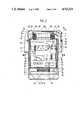
- FIG. 1illustrates a sectional view of the housing with five control devices in a modular arrangement
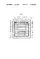
- FIG. 2is a section through the housing along line II--II of FIG. 1;
- FIG. 3is a section through the housing along line III--III in FIG. 2;
- FIG. 4is a partial section of the housing with a clamping and locking device
- FIG. 5is a partial sectional view of a modification of the device in accordance with FIG. 4.
- a housing 1, for example, made from light metalis substantially shaped with a rectangular cross section.
- Parallel guide grooves 4are molded on two opposite positioned inner walls 2 and 3, which grooves extend from the front face 5 at the open end of housing 1 to its bottom 6.
- housing 1At the outside housing 1 is provided with a flange 7 which extends parallel to the front or end face 5 on which cooling ribs 8 are formed and mounting apertures 9 are provided for mounting the housing 1 on the chassis of the motor vehicle. Moreover the housing 1 is provided with an opening 10 for a tightly sealed insertion of conduits 11 for the voltage supply and for the sensor connection.
- a central connecting plate 12is mounted parallel to the bottom 6 of housing 1.
- the connecting plate 12is a printed circuit board and supports known conductor paths, which are not shown in particular, and parallel contact bars 13 with socket plugs 14.
- the plug sockets 14are connected by means of associated conductor paths with the voltage supply and with associated sensors and as far as required, with plug sockets 14 of further contact bars 13.
- the contact bars 13belong to first detachable connecting devices, whose associated counter socket plugs 15 are provided with plug pins or flat socket plugs 16 on electric control devices 17,18,19,20,21.
- the control devices 17 to 21are connected to the voltage supply by the first connecting devices 13 to 16, while the associated sensors and indicator devices are connectable on the instrument panel and, if required, are detachably connectable to each other.
- Each control device 17 to 21has a base plate 22 which simultaneously acts as a cooling part.
- the base plate 22is provided at two opposite sides with rectangular edges 23 and 24.
- the plug pins 16 of bars 15are disposed at the edge 23 as shown in FIG. 1.
- a contact bar 25 of a second detachable connecting device and plug pins or flat plugs 26are mounted at the edge 24 as also shown in FIG. 1.
- the associated counter socket bars 27are provided with sockets 28 which are connected to conductors 29.
- Conductors 29are connected to known aggregates which are controlled (not shown in detail), to which they feed the ouput signals of the associated control devices 17 to 21. For this purpose, the conductors 29 are assembled is a module like laced wiring harness.
- Guiding edges 30 and 31are formed on the two opposite sides of the base plate 22 (FIG. 3). Each guiding edge is provided in a plane parallel to base plate 22. Each guiding edge 30 or 31 may also consist of a plurality of lugs.
- Each control device 17 to 21is provided with at least one printed circuit board 32 (FIG. 2) on which discrete and/or integrated structural components 33 are mounted.
- the structural components 33are connected with each other on the printed circuit board 32 in a known manner, not shown in detail, by means of conductor paths, also not shown in detail.
- Structural components 34 which have to be cooledare directly mounted on the base plate 22, while connecting electrodes 35 of these structural components 34 are also connected with the printed circuit board 32 by means of associated conductor paths.
- the structural components 34 which have to be cooledmay be insulated or noninsulated relative to base plate 22.
- Each control device 17 to 21is closed with a lid so as to prevent mechanical damages which may occur during the separated installation and disassembly of the individual control devices.
- a lid 36is substantially formed like a plate and is provided with two rectangular lugs 37 on two opposite sides for gripping. For closing the control devices 17, 18, 19, 20 or 21 the lid 36 is placed onto the edges 23 and 24 of base plate 22 which receive the plug bar 15 and plug bar 25, respectively whereby the lugs 37 of lid 36 extend towards the inner sides of the guide edges 30, 31 of the base plate 22 as shown in FIG. 3.
- each control device 17 to 21After each control device 17 to 21 is individually mounted, examined, compensated and closed, it is placed into housing 1 and its counter plug bar 15 is plugged into the associated contact bar 13 on the central connecting plate 12 as shown in FIG. 2. Thereby, the guiding edges 30 and 31 of the base plate 22 are received in the associated guide grooves 4 of housing 1 as shown in FIG. 3.
- the drawing off of energy heat for the structural components 34 mounted on base plate 22is performed through the base plate 22 to housing 1 and, if further required, to the chassis of the motor vehicle in which housing 1 with the control devices 17 to 21 is installed.
- a wedge 38 of a clamping and locking device(FIG. 4) is inserted into each of the guide grooves 4, which wedge presses the associated guiding edge 30 or 31 firmly into the guide groove 4, so as to facilitate heat transfer to housing 1 and to provide a large surface for drawing off heat on both sides of the base plate 22.
- the wedge 38is pushed into groove 4 by means of a collar screw 39.
- the collar screw 39is screwed with a thread having a large pitch or a bajonet lock into housing 1. Furthermore, a safety lever 40 is mounted on the head of the collar screw 39. A compression spring 41 is also seated on the collar screw 39. With one end this spring is supported on the head of the collar screw 39 and with the other end on a protrusion 42 of wedge 38 through which the collar screw 39 extends. A safety ring 43 is mounted on the collar screw 39 between the protrusion 42 of wedge 38 and housing 1 and enables a removing of the wedge 38 from guide groove 4 for releasing base plate 22.
- the compression spring 41is used for a tolerance compensation of a control device with the base plate 22 and a lid 44 between housing 1, 4, whereby the lid tightly seals housing 1 which receives the control devices 17 to 21.
- a sealing ring 45(FIGS. 1 and 2) is provided between the housing front face 5 and lid 44.
- the safety lever 40extends into a recess 46 of lid 44. Only after the collar screw 39 has been tightened by the required amount and the desired cooling effect is obtained in this manner, only then can lid 44 is mounted.
- the safety lever 40may also be formed as a central locking lever for all control devices 17 to 21 which are mounted in housing 1.
- an eccentric 47is rotatably mounted in housing 1. It is pressable against base plate 22 of one of the control devices 17 to 21 by means of an operating lever 48. Thereby, the guiding edge 30 or 31 of base plate 22 is firmly pushed into the guide groove 4 and against housing 1.
- the operating lever 48is shaped as a resilient element and engages on lid 44. Thereby, lid 44 maintains the operating lever 48 in a tolerance compensating manner in housing 1 and the eccentic 47 in its contact position.
- the lid 44is detachably mounted in a known manner and not shown in detail, for example, by means of screws on housing 1.
- the conductors 29are collected in a module like structured laced wiring harness.
- the counter socket bars 27 of the second connection devicemay also be collected in a module plug.
- the counter socket bars 27are provided each with one mounting hook 49 which engages into an opening 50 of the associated plug bar 25 as shown in FIG. 2.
- the bars 27are provided each with a locking hook 51 which engages with a pivotable locking lever 52 of plug bar 25 when the counter socket bar 27 is plugged in.
- Known coding meanswhich are not shown in detail, enable the connecting of only one counter socket bar 27 with the associated plug bar 25 of one of the control devices 17 to 21.
- the counter socket bars 27 which are collected in the module plugare mounted in housing 1 which is tightly closed by means of lid 44.
- the module like structured laced wiring harness from conductors 29is sealed and fed by means of a sealing part 53 through an opening 54 of housing 1 to the aggregates to be controlled.
- the structured laced wiring harnessmay also be fed from housing 1 through a bore 55 of lid 44 in which a sealing ring 56 is mounted.
- housing 1 with control devices 17 to 21can only be installed at only one location in the motor vehicle, whose ambient temperature requires a further cooling, such a cooling may be performed by a forced convection within housing 1.
- a forced convectionwithin housing 1.
- an intermediate bottom wall 57(FIG. 1) is formed in housing 1 between bottom 7 and connecting plate 12, which limits a chamber 58, for example, for receiving a known blower, not shown in detail.
- the intermediate bottom wall 57is provided with openings 59 through which the cooling air for the control devices 17 to 21 can circulate.
- the intermediate bottom wall 57has no openings 59.
- the total vehicle electronicis installed at a given location in the housing 1 in form of all electric control devices 17 to 21 together with their first detachable connecting means 13 to 16 and the common connecting plate, on the one hand, and their second module like collected individually detachable second connecting means 25 to 28 on the other hand.
- the input signalscan be fed in a simple manner through the base plate 22 to the individual control devices 17 to 21.
- the signal transmission between the individual control devices 17 to 21is made possible in a shortest possible path through connecting plate 12. Thereby, less interfering influences may be effective at least from the outside, so that the electromagnetic tolerance of the vehicle electronic is increased.
- the structured laced wiring consisting of conductors 29can therefore also be structured like a module depending on the type of the control devices 17 to 21 being mounted in housing 1.
- connection of the individual control devices 17 to 21 with housing 1 by means of the guiding edges 30 and 31 of base plate 22 for the individual control devices which are inserted into the guide grooves 4 of housing 1 and are firmly pressed against it by means of a clamping and locking device 38 to 44 or 47,48enable a large face heat energy draw off at both sides of base plate 22.
Landscapes
- Engineering & Computer Science (AREA)
- Microelectronics & Electronic Packaging (AREA)
- Mechanical Engineering (AREA)
- Cooling Or The Like Of Electrical Apparatus (AREA)
- Casings For Electric Apparatus (AREA)
Abstract
Description
Claims (8)
Applications Claiming Priority (2)
| Application Number | Priority Date | Filing Date | Title |
|---|---|---|---|
| DE19853514440DE3514440A1 (en) | 1985-04-20 | 1985-04-20 | HOUSING FOR RECEIVING ELECTRICAL CONTROL UNITS, ESPECIALLY FOR MOTOR VEHICLES |
| DE3514440 | 1985-04-20 |
Publications (1)
| Publication Number | Publication Date |
|---|---|
| US4763224Atrue US4763224A (en) | 1988-08-09 |
Family
ID=6268773
Family Applications (1)
| Application Number | Title | Priority Date | Filing Date |
|---|---|---|---|
| US07/019,243Expired - Fee RelatedUS4763224A (en) | 1985-04-20 | 1986-01-28 | Housing for receiving electric control devices, in particular for motor vehicles |
Country Status (5)
| Country | Link |
|---|---|
| US (1) | US4763224A (en) |
| EP (1) | EP0220196B1 (en) |
| JP (1) | JPS62502531A (en) |
| DE (2) | DE3514440A1 (en) |
| WO (1) | WO1986006334A1 (en) |
Cited By (20)
| Publication number | Priority date | Publication date | Assignee | Title |
|---|---|---|---|---|
| DE8815441U1 (en)* | 1988-12-13 | 1989-03-23 | Lohmeier Schaltschranksysteme GmbH & Co KG, 4973 Vlotho | Control unit for machines and systems |
| US5159532A (en)* | 1988-11-09 | 1992-10-27 | Telefunken Electronic Gmbh | Electronic control unit with multiple hybrid circuit assemblies integrated on a single common ceramic carrier |
| DE4117179A1 (en)* | 1991-05-25 | 1992-11-26 | Daimler Benz Ag | Electronic controller built into motor vehicle engine compartment - is protected against overheating by air space in plastics material hood a defined distance from connector housing |
| US5594199A (en)* | 1995-03-23 | 1997-01-14 | Ford Motor Company | EMI baffle for electronic control |
| US5789704A (en)* | 1995-12-06 | 1998-08-04 | Sumitomo Wiring Systems, Ltd. | Container with heat removing features for containing an electronic contol unit |
| US6008454A (en)* | 1997-02-25 | 1999-12-28 | Sumitomo Wiring Systems, Ltd. | Storage box for electronic control units |
| US6052283A (en)* | 1997-02-13 | 2000-04-18 | Sumitomo Wiring Systems, Ltd. | Storage units |
| WO1999044259A3 (en)* | 1998-02-24 | 2000-06-22 | Lear Automotive Dearborn Inc | Module carrier for two modules |
| FR2791517A1 (en)* | 1999-03-25 | 2000-09-29 | Mannesmann Sachs Ag | ELECTRONIC POWER UNIT FOR CONTROLLING AN ELECTRIC GROUP |
| EP0904987A3 (en)* | 1997-09-24 | 2001-05-23 | Sumitomo Wiring Systems, Ltd. | Electrical connection box |
| US6273181B1 (en)* | 1998-07-22 | 2001-08-14 | Denso Corporation | Cooling device for electronic parts of vehicle |
| US6347953B1 (en) | 1998-02-24 | 2002-02-19 | Lear Corporation | Module carrier for two modules |
| US6510223B2 (en) | 1997-11-06 | 2003-01-21 | Anacapa Technology, Inc. | Local loop telecommunication repeater housings employing thermal collection, transfer and distribution via solid thermal conduction |
| US6590752B1 (en)* | 1999-04-19 | 2003-07-08 | Phoenix Contact Gmbh & Co. | Electronic control device |
| US20030142481A1 (en)* | 2002-01-31 | 2003-07-31 | Kenji Kinoshita | Intake module having integrated ECU |
| US6657869B1 (en) | 1999-03-17 | 2003-12-02 | Trw Automotive Electronics & Components Gmbh & Co. Kg | Metal housing, especially for an airbag control device |
| US6785138B1 (en) | 2002-09-05 | 2004-08-31 | Added Communications Of Georgia, Inc. | Repeater case for HDSL modules |
| US20050103469A1 (en)* | 2003-10-10 | 2005-05-19 | Michel Brun | Device for exchanging heat |
| US20080117591A1 (en)* | 2006-11-16 | 2008-05-22 | Autonetworks Technologies, Ltd. | Electric connection box |
| CN102868120A (en)* | 2011-07-05 | 2013-01-09 | 株式会社自动网络技术研究所 | Wiring tool, wiring harness and manufacture method thereof |
Families Citing this family (26)
| Publication number | Priority date | Publication date | Assignee | Title |
|---|---|---|---|---|
| US5414416A (en)* | 1901-09-03 | 1995-05-09 | Nippondenso Co., Ltd. | Temperature dependent control module cluster unit for motor vehicle |
| DE3906973A1 (en)* | 1989-03-04 | 1990-09-13 | Telefunken Electronic Gmbh | Housing for motor-vehicle electronics |
| DE3920602C1 (en)* | 1989-06-23 | 1990-09-13 | Audi Ag, 8070 Ingolstadt, De | Protective shield for pulling magnets of starter motor of IC engine - is composed of thin-walled plate and has 3 spacers uniformly distributed about periphery |
| DE4016557A1 (en)* | 1989-07-29 | 1991-01-31 | Iveco Magirus | ELECTRONIC CONTROL UNIT FOR COMMERCIAL VEHICLES |
| DE3936906C2 (en)* | 1989-11-06 | 1995-02-02 | Telefunken Microelectron | Housing for automotive electronics |
| DE4009321A1 (en)* | 1990-03-23 | 1991-09-26 | Porsche Ag | CONTROL UNIT |
| DE4041016C1 (en)* | 1990-12-20 | 1992-07-16 | Audi Ag, 8070 Ingolstadt, De | |
| DE4112022A1 (en)* | 1991-04-12 | 1992-10-15 | Telefunken Electronic Gmbh | HOUSING FOR INSTALLATION IN MOTOR VEHICLES TO RECEIVE ELECTRONIC COMPONENTS |
| DE9106035U1 (en)* | 1991-05-16 | 1992-09-24 | GKR Gesellschaft für Fahrzeugklimaregelung mbH, 71701 Schwieberdingen | Power controller for fan motors |
| DE4122897C1 (en)* | 1991-07-11 | 1992-06-11 | Mercedes-Benz Aktiengesellschaft, 7000 Stuttgart, De | Control unit housing for motor vehicle - is surrounded by screened housing for protection of electronics from engine heat |
| DE4123261C1 (en)* | 1991-07-13 | 1993-01-14 | Mercedes-Benz Aktiengesellschaft, 7000 Stuttgart, De | |
| DE4137112A1 (en)* | 1991-11-12 | 1993-05-13 | Bayerische Motoren Werke Ag | Local screen for car electronic control components - is fitted directly to interference causing component, such as microprocessor |
| JPH06216544A (en)* | 1993-01-12 | 1994-08-05 | Sumitomo Wiring Syst Ltd | Water-proof case |
| DE4313782C2 (en)* | 1993-04-27 | 1997-09-18 | Daimler Benz Ag | Device for fastening electronic control units in a motor vehicle |
| DE4436235C2 (en)* | 1994-10-11 | 1998-01-29 | Daimler Benz Ag | Housing for receiving electrical control devices for a motor vehicle |
| DE4443501A1 (en)* | 1994-12-07 | 1996-06-13 | Bosch Gmbh Robert | Electric device |
| FR2745148B1 (en)* | 1996-02-15 | 1998-04-10 | Sagem | POWER SUPPLY FOR ELECTRIC VEHICLE |
| JP3052843B2 (en)* | 1996-07-03 | 2000-06-19 | 住友電装株式会社 | Electrical junction box |
| DE19715592C2 (en)* | 1997-04-15 | 1999-12-09 | Bosch Gmbh Robert | Cooling device for an electronic module |
| FR2804574B1 (en)* | 2000-01-28 | 2004-07-23 | Siemens Automotive Sa | CONTROL BOX FOR ANTI-LOCKING DEVICE |
| DE202014104445U1 (en) | 2014-09-18 | 2014-09-25 | Dr. Ing. H.C. F. Porsche Aktiengesellschaft | Arrangement of at least one electronic control unit in a motor vehicle |
| EP3319406B1 (en)* | 2016-11-02 | 2020-09-23 | WABCO Europe BVBA | Closing system for dust cover |
| DE102020127026A1 (en) | 2020-10-14 | 2022-04-14 | Bayerische Motoren Werke Aktiengesellschaft | Holder for a control unit of a vehicle and vehicle |
| WO2023278006A1 (en)* | 2021-06-29 | 2023-01-05 | Apple Inc. | Consolidated electronics packaging |
| US12077110B2 (en) | 2021-06-29 | 2024-09-03 | Apple Inc. | Consolidated electronics packaging |
| DE102022208808A1 (en)* | 2022-08-25 | 2024-03-07 | Robert Bosch Gesellschaft mit beschränkter Haftung | Device for cooling a unit to be cooled, particularly of a motor vehicle |
Citations (5)
| Publication number | Priority date | Publication date | Assignee | Title |
|---|---|---|---|---|
| US3601661A (en)* | 1970-02-02 | 1971-08-24 | Westinghouse Air Brake Co | Finned modular electrical equipment package with mounting bracket |
| US4480287A (en)* | 1982-12-27 | 1984-10-30 | Raytheon Company | Module retainer apparatus |
| US4498119A (en)* | 1980-11-03 | 1985-02-05 | Lockheed Corporation | Electronic circuit board and method and apparatus for thermal management thereof |
| US4546407A (en)* | 1983-10-31 | 1985-10-08 | Salvatore Benenati | Heat exchanging electronic module housing |
| US4628413A (en)* | 1985-12-18 | 1986-12-09 | Ncr Corporation | Card cassette ejector apparatus |
Family Cites Families (5)
| Publication number | Priority date | Publication date | Assignee | Title |
|---|---|---|---|---|
| GB1361139A (en)* | 1972-10-27 | 1974-07-24 | Mel Equipment Co Ltd | Housing for electrical apparatus |
| FR2223318B1 (en)* | 1973-03-30 | 1978-03-03 | Saint Gobain | |
| DE2409660A1 (en)* | 1974-02-28 | 1975-09-25 | Siemens Ag | Electrical control system for motor vehicle switch gear - has housing with printed circuit and plug in control unitss and fuses |
| US4172272A (en)* | 1978-05-01 | 1979-10-23 | International Rectifier Corporation | Solid state relay having U-shaped conductive heat sink frame |
| JPS5738782Y2 (en)* | 1980-09-09 | 1982-08-26 |
- 1985
- 1985-04-20DEDE19853514440patent/DE3514440A1/ennot_activeWithdrawn
- 1986
- 1986-01-28EPEP86900744Apatent/EP0220196B1/ennot_activeExpired
- 1986-01-28JPJP61500885Apatent/JPS62502531A/enactivePending
- 1986-01-28WOPCT/DE1986/000028patent/WO1986006334A1/enactiveIP Right Grant
- 1986-01-28USUS07/019,243patent/US4763224A/ennot_activeExpired - Fee Related
- 1986-01-28DEDE8686900744Tpatent/DE3660371D1/ennot_activeExpired
Patent Citations (5)
| Publication number | Priority date | Publication date | Assignee | Title |
|---|---|---|---|---|
| US3601661A (en)* | 1970-02-02 | 1971-08-24 | Westinghouse Air Brake Co | Finned modular electrical equipment package with mounting bracket |
| US4498119A (en)* | 1980-11-03 | 1985-02-05 | Lockheed Corporation | Electronic circuit board and method and apparatus for thermal management thereof |
| US4480287A (en)* | 1982-12-27 | 1984-10-30 | Raytheon Company | Module retainer apparatus |
| US4546407A (en)* | 1983-10-31 | 1985-10-08 | Salvatore Benenati | Heat exchanging electronic module housing |
| US4628413A (en)* | 1985-12-18 | 1986-12-09 | Ncr Corporation | Card cassette ejector apparatus |
Cited By (27)
| Publication number | Priority date | Publication date | Assignee | Title |
|---|---|---|---|---|
| US5159532A (en)* | 1988-11-09 | 1992-10-27 | Telefunken Electronic Gmbh | Electronic control unit with multiple hybrid circuit assemblies integrated on a single common ceramic carrier |
| DE8815441U1 (en)* | 1988-12-13 | 1989-03-23 | Lohmeier Schaltschranksysteme GmbH & Co KG, 4973 Vlotho | Control unit for machines and systems |
| DE4117179A1 (en)* | 1991-05-25 | 1992-11-26 | Daimler Benz Ag | Electronic controller built into motor vehicle engine compartment - is protected against overheating by air space in plastics material hood a defined distance from connector housing |
| US5594199A (en)* | 1995-03-23 | 1997-01-14 | Ford Motor Company | EMI baffle for electronic control |
| US5789704A (en)* | 1995-12-06 | 1998-08-04 | Sumitomo Wiring Systems, Ltd. | Container with heat removing features for containing an electronic contol unit |
| US6052283A (en)* | 1997-02-13 | 2000-04-18 | Sumitomo Wiring Systems, Ltd. | Storage units |
| US6008454A (en)* | 1997-02-25 | 1999-12-28 | Sumitomo Wiring Systems, Ltd. | Storage box for electronic control units |
| EP0904987A3 (en)* | 1997-09-24 | 2001-05-23 | Sumitomo Wiring Systems, Ltd. | Electrical connection box |
| US6798878B2 (en) | 1997-11-06 | 2004-09-28 | Anacapa Technology, Inc. | Local loop telecommunication repeater housing having mounting slots enabling replaceable repeater and voltage protector assemblies |
| US6535603B2 (en) | 1997-11-06 | 2003-03-18 | Anacapa Technology, Inc. | Local loop telecommunication repeater housings employing thermal collection, transfer and distribution via solid thermal conduction |
| US6510223B2 (en) | 1997-11-06 | 2003-01-21 | Anacapa Technology, Inc. | Local loop telecommunication repeater housings employing thermal collection, transfer and distribution via solid thermal conduction |
| US6347953B1 (en) | 1998-02-24 | 2002-02-19 | Lear Corporation | Module carrier for two modules |
| WO1999044259A3 (en)* | 1998-02-24 | 2000-06-22 | Lear Automotive Dearborn Inc | Module carrier for two modules |
| US6273181B1 (en)* | 1998-07-22 | 2001-08-14 | Denso Corporation | Cooling device for electronic parts of vehicle |
| US6657869B1 (en) | 1999-03-17 | 2003-12-02 | Trw Automotive Electronics & Components Gmbh & Co. Kg | Metal housing, especially for an airbag control device |
| FR2791517A1 (en)* | 1999-03-25 | 2000-09-29 | Mannesmann Sachs Ag | ELECTRONIC POWER UNIT FOR CONTROLLING AN ELECTRIC GROUP |
| US6326761B1 (en) | 1999-03-25 | 2001-12-04 | Mannesmann Sachs Ag | Power electronics device for controlling an electric machine |
| US6590752B1 (en)* | 1999-04-19 | 2003-07-08 | Phoenix Contact Gmbh & Co. | Electronic control device |
| US20030142481A1 (en)* | 2002-01-31 | 2003-07-31 | Kenji Kinoshita | Intake module having integrated ECU |
| US6788534B2 (en)* | 2002-01-31 | 2004-09-07 | Denso Corporation | Intake module having integrated ECU |
| US6785138B1 (en) | 2002-09-05 | 2004-08-31 | Added Communications Of Georgia, Inc. | Repeater case for HDSL modules |
| US20050103469A1 (en)* | 2003-10-10 | 2005-05-19 | Michel Brun | Device for exchanging heat |
| US7394044B2 (en)* | 2003-10-10 | 2008-07-01 | Behr France Rouffach Sas | Device for exchanging heat |
| US20080117591A1 (en)* | 2006-11-16 | 2008-05-22 | Autonetworks Technologies, Ltd. | Electric connection box |
| US8654528B2 (en)* | 2006-11-16 | 2014-02-18 | Autonetworks Technologies, Ltd. | Electric connection box |
| CN102868120A (en)* | 2011-07-05 | 2013-01-09 | 株式会社自动网络技术研究所 | Wiring tool, wiring harness and manufacture method thereof |
| US20130008712A1 (en)* | 2011-07-05 | 2013-01-10 | Autonetworks Technologies, Ltd. | Wiring tool and wiring harness |
Also Published As
| Publication number | Publication date |
|---|---|
| JPS62502531A (en) | 1987-10-01 |
| DE3514440A1 (en) | 1986-10-23 |
| EP0220196A1 (en) | 1987-05-06 |
| WO1986006334A1 (en) | 1986-11-06 |
| EP0220196B1 (en) | 1988-07-13 |
| DE3660371D1 (en) | 1988-08-18 |
Similar Documents
| Publication | Publication Date | Title |
|---|---|---|
| US4763224A (en) | Housing for receiving electric control devices, in particular for motor vehicles | |
| US4519667A (en) | Electrical connector | |
| US5385487A (en) | Apparatus for electrically operating devices in a controlled environment | |
| US20100127602A1 (en) | Frequency converter for controlling an electric motor | |
| US3221216A (en) | Meter mount | |
| US6782617B2 (en) | Electrical equipment and method of assembling same | |
| JP3749735B2 (en) | Electrical control equipment | |
| US4217624A (en) | Communications interface adapter | |
| US6227913B1 (en) | Fuse bus member and connector assembly | |
| CA1310393C (en) | Ventilated splash resistant electrical component housing | |
| US6203293B1 (en) | Electric fan apparatus, connector connection structure, and intermediate terminal | |
| CN103370996A (en) | Electrical device | |
| KR900001364B1 (en) | Circuit assembly | |
| US3582714A (en) | Multiple-output chassis-less power supply having a heat dissipating housing of unitary construction | |
| CN114079195B (en) | Electric vehicle charging connector | |
| US6166909A (en) | Switch box for a vehicle | |
| WO2022196961A1 (en) | Housing unit for an electronic component of an electrical refrigerant compressor | |
| US5280410A (en) | Electrical switching and control device, in particular for motor vehicles | |
| HU224398B1 (en) | Endshield assembly for an electric motor and method of assembling endshield assembly | |
| US5771151A (en) | Central electrical assembly | |
| US20180301772A1 (en) | Power storage unit | |
| DE19911196C2 (en) | Enclosure electrification means | |
| US20200259301A1 (en) | Plug connector | |
| CN119340714A (en) | Charging inlet assembly with power wiring harness | |
| US5323296A (en) | I/O device including circuit board non-rigidly supported by elastically deformable terminal pins extending from a connector strip |
Legal Events
| Date | Code | Title | Description |
|---|---|---|---|
| AS | Assignment | Owner name:ROBERT BOSCH GMBH, POSTFACH 50, D-7000 STUTTGART 1 Free format text:ASSIGNMENT OF ASSIGNORS INTEREST.;ASSIGNORS:BENTZ, WILLY;GANSERT, WILLI;REEL/FRAME:004853/0986;SIGNING DATES FROM 19860709 TO 19860710 Owner name:ROBERT BOSCH GMBH, GERMANY Free format text:ASSIGNMENT OF ASSIGNORS INTEREST;ASSIGNORS:BENTZ, WILLY;GANSERT, WILLI;SIGNING DATES FROM 19860709 TO 19860710;REEL/FRAME:004853/0986 | |
| FEPP | Fee payment procedure | Free format text:PAYOR NUMBER ASSIGNED (ORIGINAL EVENT CODE: ASPN); ENTITY STATUS OF PATENT OWNER: LARGE ENTITY | |
| AS | Assignment | Owner name:MARTIN-DECKER TOTCO, INC. Free format text:CHANGE OF NAME;ASSIGNOR:MARTIN-DECKER, INC.;REEL/FRAME:005829/0095 Effective date:19910220 | |
| REMI | Maintenance fee reminder mailed | ||
| FPAY | Fee payment | Year of fee payment:4 | |
| SULP | Surcharge for late payment | ||
| FEPP | Fee payment procedure | Free format text:PAYER NUMBER DE-ASSIGNED (ORIGINAL EVENT CODE: RMPN); ENTITY STATUS OF PATENT OWNER: LARGE ENTITY Free format text:PAYOR NUMBER ASSIGNED (ORIGINAL EVENT CODE: ASPN); ENTITY STATUS OF PATENT OWNER: LARGE ENTITY | |
| REMI | Maintenance fee reminder mailed | ||
| LAPS | Lapse for failure to pay maintenance fees | ||
| FP | Lapsed due to failure to pay maintenance fee | Effective date:19960814 | |
| STCH | Information on status: patent discontinuation | Free format text:PATENT EXPIRED DUE TO NONPAYMENT OF MAINTENANCE FEES UNDER 37 CFR 1.362 |