US4763130A - Probe-fed slot antenna with coupling ring - Google Patents
Probe-fed slot antenna with coupling ringDownload PDFInfo
- Publication number
- US4763130A US4763130AUS07/048,955US4895587AUS4763130AUS 4763130 AUS4763130 AUS 4763130AUS 4895587 AUS4895587 AUS 4895587AUS 4763130 AUS4763130 AUS 4763130A
- Authority
- US
- United States
- Prior art keywords
- probe
- slot antenna
- coupling ring
- fed slot
- outer conductor
- Prior art date
- Legal status (The legal status is an assumption and is not a legal conclusion. Google has not performed a legal analysis and makes no representation as to the accuracy of the status listed.)
- Expired - Lifetime
Links
- 239000000523sampleSubstances0.000titleclaimsabstractdescription66
- 230000008878couplingEffects0.000titleclaimsabstractdescription53
- 238000010168coupling processMethods0.000titleclaimsabstractdescription53
- 238000005859coupling reactionMethods0.000titleclaimsabstractdescription53
- 239000004020conductorSubstances0.000claimsabstractdescription89
- 230000005540biological transmissionEffects0.000claimsdescription18
- 230000005855radiationEffects0.000claimsdescription9
- 230000004323axial lengthEffects0.000claims2
- 229910052782aluminiumInorganic materials0.000description4
- XAGFODPZIPBFFR-UHFFFAOYSA-NaluminiumChemical compound[Al]XAGFODPZIPBFFR-UHFFFAOYSA-N0.000description4
- 239000000463materialSubstances0.000description2
- 230000006978adaptationEffects0.000description1
- 230000000694effectsEffects0.000description1
- 229910052751metalInorganic materials0.000description1
- 239000002184metalSubstances0.000description1
- 238000000034methodMethods0.000description1
- 238000012986modificationMethods0.000description1
- 230000004048modificationEffects0.000description1
- 230000005404monopoleEffects0.000description1
- 230000000149penetrating effectEffects0.000description1
- 238000007493shaping processMethods0.000description1
- 229910052709silverInorganic materials0.000description1
- 239000004332silverSubstances0.000description1
- 230000001131transforming effectEffects0.000description1
Images
Classifications
- H—ELECTRICITY
- H01—ELECTRIC ELEMENTS
- H01Q—ANTENNAS, i.e. RADIO AERIALS
- H01Q21/00—Antenna arrays or systems
- H01Q21/06—Arrays of individually energised antenna units similarly polarised and spaced apart
- H01Q21/20—Arrays of individually energised antenna units similarly polarised and spaced apart the units being spaced along or adjacent to a curvilinear path
- H—ELECTRICITY
- H01—ELECTRIC ELEMENTS
- H01Q—ANTENNAS, i.e. RADIO AERIALS
- H01Q13/00—Waveguide horns or mouths; Slot antennas; Leaky-waveguide antennas; Equivalent structures causing radiation along the transmission path of a guided wave
- H01Q13/10—Resonant slot antennas
- H01Q13/12—Longitudinally slotted cylinder antennas; Equivalent structures
Definitions
- the present inventionrelates to a new and improved antenna and more particularly, to an omnidirectional, horizontally polarized probe-fed slot antenna having a conductive coupling ring for efficient coupling of RF energy within the antenna.
- Slot antennasare constructed by cutting one or more slots in the wall of a radio frequency ("RF") transmission line to provide an efficient transfer of RF energy between each slot and the transmission line, thereby providing a good return loss for the antenna.
- RFradio frequency
- RF energy in a slot antennais accomplished when the placement of the slot interrupts RF currents on the wall of the transmission line.
- transfer of RF energymay be accomplished by the use of a conductive probe adjacent to the slot and penetrating into the transmission line.
- a conductive probeadjacent to the slot and penetrating into the transmission line.
- Such a designis useful, for example, in an antenna where an omnidirectional, horizontally polarized radiation pattern is desired.
- the conductive probeWhen such an antenna is used in the transmitting mode, the conductive probe "feeds" RF energy from the transmission line to the slot which then radiates the energy into the external environment.
- probe-fed slot antennasare often referred to as probe-fed slot antennas.
- antennassuch as beacon antennas or antennas used with active decoys which, due to size and antenna pattern constraints, cannot be provided with additional sets of cascaded slots to improve the RF energy coupling. It would therefore be advantageous to provide a probe-fed slot antenna having improved coupling of RF energy between the transmission line and slots without resorting to multiple sets of slots. Such an antenna should provide an improved return loss, for example on the order of 15 dB or greater at the antenna's operating frequency.
- the present inventionprovides a probe-fed slot antenna meeting these requirements.
- a coupling ringis provided in a probe-fed slot antenna.
- the coupling ringeffects efficient coupling of RF energy between the transmission line and slots.
- the antennacomprises an inner conductor, a cylindrical outer conductor which is spaced about and typically coaxial with the inner conductor, and a plurality of slots in the outer conductor.
- a plurality of probesextends from the cylindrical outer conductor toward a coupling ring that is mounted coaxially between the outer and inner conductors.
- the probesare in electrical contact with the coupling ring and serve as the mounting means which secures the coupling ring between the outer and inner conductors.
- a shorting plate mounted at one end of the outer conductorelectrically connects the outer conductor to the inner conductor.
- a ground planecan be mounted at the other end of the outer conductor in order to shape the antenna radiation pattern.
- the inner conductorcan be a conductive rod, for example of aluminum.
- the probescan comprise conductive rods which, when the antenna is designed to provide an omnidirectional, horizontally polarized radiation pattern, are mounted perpendicular to the axis of the inner and outer conductors.
- the probescan be adjustable longitudinally along their axis to accommodate coupling rings of various sizes and thereby provide fine tuning.
- the length of the slotsis preferably about one-half the wavelength of radiation to be received or transmitted by the antenna.
- the slotsare equally spaced around the cylindrical outer conductor and run longitudinally in the cylindrical outer conductor.
- the diameter and length of the coupling ringare selected to maximize the return loss at the operating frequency of the antenna.
- the height of the coupling ringis preferably between about one-quarter to one-half the height of the cylindrical outer conductor.
- the diameter of the coupling ringis preferably between about three-eighths to three-quarters of the diameter of the outer conductor.
- the coupling ringis generally centered between the ends of the cylindrical outer conductor.
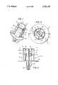
- FIG. 1is a perspective view of a probe-fed slot antenna in accordance with the present invention
- FIG. 2is a top cross-sectional view of the antenna of FIG. 1, taken along the lines 2--2 shown in FIG. 3;
- FIG. 3is a cross-sectional view of the antenna of FIG. 1, taken along the lines 3--3 shown in FIG. 2.
- the present inventionprovides an improved probefed slot antenna having a coupling ring in electrical contact with the inner ends of the probes in order to achieve an efficient coupling of RF energy between the transmission line and the slots, resulting in an improved antenna return loss.
- a conductive cylindrical outer conductor 12is fabricated, for example, of aluminum or other metal as is typical in the antenna art. Cylindrical outer conductor 12 contains a plurality of nominally half-wave slots 18 equally spaced around the circumference thereof.
- a conductive probe 20is mounted adjacent to each slot 18 and extends through the cylindrical outer conductor 12 from the interior to the exterior thereof. Probes 20 can be adjustable to slide along their axes into and out from cylindrical conductor 12. Probes 20 are typically conductive rods fabricated from the same material which is used for outer conductor 12. It is noted that in accordance with the present invention, probes 20 do not have to actually extend through the wall of outer conductor 12 to the exterior thereof; they need only make contact with the interior wall of the outer conductor to provide proper operation.
- An inner conductor 14is arranged coaxially with outer conductor 12.
- the inner conductoris typically fabricated of the same conductive material as the outer conductor 12 and probes 20.
- a shorting plate 16electrically connects inner conductor 14 to outer conductor 12 at one end of the outer conductor.
- a ground plane 22can be connected at the other end of outer conductor 12 to provide beam shaping of radiation transmitted from the antenna. Without ground plane 22, radiation will emanate perpendicularly from the antenna axis.
- Ground plane 22comprises a disk which is sized according to the angle of radiation desired in accordance with well-known techniques. In the embodiment shown in the drawings, energy is radiated from the antenna at an angle of approximately 60°-70° from the antenna axis.
- the antennaproduces a horizontally polarized radiation pattern which substantially matches that of a quarter-wave vertically polarized monopole antenna above a finite ground plane.
- a transforming section 24is provided to step down the diameter of the coaxial transmission line (i.e., inner conductor 14 and outer conductor 12) to a smaller size which is compatible with a conventional type N RF connector 26.
- the coaxial transmission linei.e., inner conductor 14 and outer conductor 12
- a conventional type N RF connector 26Those skilled in the art will appreciate that other types of connectors can be coupled to the antenna. Alternately, the present invention can be applied to antennas constructed on waveguide transmission lines.
- a coupling ring 30is mounted coaxially between outer conductor 12 and inner conductor 14.
- Coupling ring 30is fabricated from a conductive material, preferably the same material used for the inner and outer conductors and the probes.
- the coupling ringprovides efficient coupling of RF energy between the transmission line (i.e., inner and outer conductors 14, 12) and the slots 18.
- the diameter and length of the coupling ringis established empirically, to achieve a desirable return loss.
- An antennawas constructed in accordance with the present invention to provide omnidirectional, horizontally polarized operation at 3.1 gigahertz (GHz). It consisted of one set of six, nominally half-wave slots equally spaced around the outer conductor of a coaxial transmission line.
- Outer conductor 12was a two inch diameter aluminum tube approximately two and one-half inches long.
- a ground plane 22 having a five inch diameterwas conductively attached around the circumference of outer conductor 12 as shown in the figures.
- Inner conductor 14was fabricated from a one-quarter inch aluminum rod. The width of the six slots was approximately three-sixteenths of an inch each, and the slot length was two and one-quarter inches.
- Six probes 20were used, each having a length of approximately three-eighths inch.
- each probeelectrically contacted and supported a coupling ring 30.
- the outer ends of each probewere flush with the outside wall of outer conductor 12.
- the diameter of coupling ring 30was approximately one and one-quarter inches and the coupling ring had a height of approximately 0.85 inches.
- the return loss of the probe-fed slot antenna with the coupling ring described abovewas measured at greater than 15 dB at the operating frequency of 3.1 GHz and greater than 10 dB for all frequencies between 2.95 GHz and 3.25 GHz. When the coupling ring was removed, the return loss dropped to no greater than 3 dB for any probe depth.
- the present inventionenables a probe-fed slot antenna to achieve an improved return loss by enabling efficient coupling of RF energy between the transmission line and slots. Such efficient coupling is not achieved without the use of the coupling ring.
Landscapes
- Waveguide Aerials (AREA)
Abstract
Description
Claims (23)
Priority Applications (1)
| Application Number | Priority Date | Filing Date | Title |
|---|---|---|---|
| US07/048,955US4763130A (en) | 1987-05-11 | 1987-05-11 | Probe-fed slot antenna with coupling ring |
Applications Claiming Priority (1)
| Application Number | Priority Date | Filing Date | Title |
|---|---|---|---|
| US07/048,955US4763130A (en) | 1987-05-11 | 1987-05-11 | Probe-fed slot antenna with coupling ring |
Publications (1)
| Publication Number | Publication Date |
|---|---|
| US4763130Atrue US4763130A (en) | 1988-08-09 |
Family
ID=21957341
Family Applications (1)
| Application Number | Title | Priority Date | Filing Date |
|---|---|---|---|
| US07/048,955Expired - LifetimeUS4763130A (en) | 1987-05-11 | 1987-05-11 | Probe-fed slot antenna with coupling ring |
Country Status (1)
| Country | Link |
|---|---|
| US (1) | US4763130A (en) |
Cited By (19)
| Publication number | Priority date | Publication date | Assignee | Title |
|---|---|---|---|---|
| GB2245767A (en)* | 1990-05-23 | 1992-01-08 | Marconi Gec Ltd | Microwaves antennas |
| US5220337A (en)* | 1991-05-24 | 1993-06-15 | Hughes Aircraft Company | Notched nested cup multi-frequency band antenna |
| US5717410A (en)* | 1994-05-20 | 1998-02-10 | Mitsubishi Denki Kabushiki Kaisha | Omnidirectional slot antenna |
| US5929821A (en)* | 1998-04-03 | 1999-07-27 | Harris Corporation | Slot antenna |
| US6157346A (en)* | 1996-05-03 | 2000-12-05 | Garmin Corporation | Hexafilar slot antenna |
| JP3176217B2 (en) | 1993-05-21 | 2001-06-11 | 三菱電機株式会社 | Antenna device |
| US20030080913A1 (en)* | 2001-10-29 | 2003-05-01 | George Harris | Broad band slot style television broadcast antenna |
| US20040135734A1 (en)* | 2002-10-30 | 2004-07-15 | Kouichi Uesaka | Narrow-directivity electromagnetic-field antenna probe, and electromagnetic-field measurement apparatus, electric-current distribution search-for apparatus or electrical-wiring diagnosis apparatus using this antenna probe |
| US7908080B2 (en) | 2004-12-31 | 2011-03-15 | Google Inc. | Transportation routing |
| CN1996661B (en)* | 2006-12-29 | 2011-04-20 | 北京交通大学 | Method for making the vehicular antennal with the leaky coaxial cable |
| US20110156720A1 (en)* | 2008-06-11 | 2011-06-30 | Antonio Di Stefano | Portable partial discharge detection device |
| DE102010011867A1 (en)* | 2010-03-18 | 2011-09-22 | Kathrein-Werke Kg | Broadband omnidirectional antenna |
| EP2618425A1 (en)* | 2012-01-18 | 2013-07-24 | Ott-Jakob Spanntechnik GmbH | Antenna cover |
| US8779998B1 (en)* | 2010-09-21 | 2014-07-15 | The United States Of America, As Represented By The Secretary Of The Navy | Wideband horizontally polarized omnidirectional antenna |
| CN104062492A (en)* | 2014-06-13 | 2014-09-24 | 清华大学 | Radio-frequency power measurement system |
| RU2593422C1 (en)* | 2015-05-15 | 2016-08-10 | Российская Федерация, от имени которой выступает Государственная корпорация по атомной энергии "Росатом" (Госкорпорация "Росатом") | Annular slit antenna |
| US9425515B2 (en)* | 2012-03-23 | 2016-08-23 | Lhc2 Inc | Multi-slot common aperture dual polarized omni-directional antenna |
| CN112993581A (en)* | 2021-02-23 | 2021-06-18 | 普联国际有限公司 | Gap antenna system and intelligent bulb system |
| US11527830B2 (en)* | 2020-01-28 | 2022-12-13 | Nokia Solutions And Networks Oy | Antenna system with radiator extensions |
Citations (4)
| Publication number | Priority date | Publication date | Assignee | Title |
|---|---|---|---|---|
| US2971193A (en)* | 1957-06-21 | 1961-02-07 | Rca Corp | Multiple slot antenna having radiating termination |
| US4197549A (en)* | 1977-08-17 | 1980-04-08 | Harris Corporation | Slot antenna |
| US4297707A (en)* | 1976-06-30 | 1981-10-27 | Siemens Aktiengesellschaft | Multiple omnidirectional antenna |
| US4631544A (en)* | 1985-04-10 | 1986-12-23 | Tideland Signal Corporation | S-band coaxial slot array antenna |
- 1987
- 1987-05-11USUS07/048,955patent/US4763130A/ennot_activeExpired - Lifetime
Patent Citations (4)
| Publication number | Priority date | Publication date | Assignee | Title |
|---|---|---|---|---|
| US2971193A (en)* | 1957-06-21 | 1961-02-07 | Rca Corp | Multiple slot antenna having radiating termination |
| US4297707A (en)* | 1976-06-30 | 1981-10-27 | Siemens Aktiengesellschaft | Multiple omnidirectional antenna |
| US4197549A (en)* | 1977-08-17 | 1980-04-08 | Harris Corporation | Slot antenna |
| US4631544A (en)* | 1985-04-10 | 1986-12-23 | Tideland Signal Corporation | S-band coaxial slot array antenna |
Cited By (35)
| Publication number | Priority date | Publication date | Assignee | Title |
|---|---|---|---|---|
| GB2245767A (en)* | 1990-05-23 | 1992-01-08 | Marconi Gec Ltd | Microwaves antennas |
| US5200757A (en)* | 1990-05-23 | 1993-04-06 | Gec-Marconi Limited | Microwave antennas having both wide elevation beamwidth and a wide azimuth beamwidth over a wide frequency bandwidth |
| GB2245767B (en)* | 1990-05-23 | 1994-09-21 | Marconi Gec Ltd | Microwave antennas |
| US5220337A (en)* | 1991-05-24 | 1993-06-15 | Hughes Aircraft Company | Notched nested cup multi-frequency band antenna |
| JP3176217B2 (en) | 1993-05-21 | 2001-06-11 | 三菱電機株式会社 | Antenna device |
| US5717410A (en)* | 1994-05-20 | 1998-02-10 | Mitsubishi Denki Kabushiki Kaisha | Omnidirectional slot antenna |
| US6157346A (en)* | 1996-05-03 | 2000-12-05 | Garmin Corporation | Hexafilar slot antenna |
| US5929821A (en)* | 1998-04-03 | 1999-07-27 | Harris Corporation | Slot antenna |
| US6784848B2 (en)* | 2001-10-29 | 2004-08-31 | Rf Technologies Corporation | Broad band slot style television broadcast antenna |
| US20030080913A1 (en)* | 2001-10-29 | 2003-05-01 | George Harris | Broad band slot style television broadcast antenna |
| US20040135734A1 (en)* | 2002-10-30 | 2004-07-15 | Kouichi Uesaka | Narrow-directivity electromagnetic-field antenna probe, and electromagnetic-field measurement apparatus, electric-current distribution search-for apparatus or electrical-wiring diagnosis apparatus using this antenna probe |
| US7132997B2 (en)* | 2002-10-30 | 2006-11-07 | Hitachi, Ltd. | Narrow-directivity electromagnetic-field antenna probe, and electromagnetic-field measurement apparatus, electric-current distribution search-for apparatus or electrical-wiring diagnosis apparatus using this antenna probe |
| US11092455B2 (en) | 2004-12-31 | 2021-08-17 | Google Llc | Transportation routing |
| US7908080B2 (en) | 2004-12-31 | 2011-03-15 | Google Inc. | Transportation routing |
| US8798917B2 (en) | 2004-12-31 | 2014-08-05 | Google Inc. | Transportation routing |
| US9945686B2 (en) | 2004-12-31 | 2018-04-17 | Google Llc | Transportation routing |
| US9778055B2 (en) | 2004-12-31 | 2017-10-03 | Google Inc. | Transportation routing |
| US9709415B2 (en) | 2004-12-31 | 2017-07-18 | Google Inc. | Transportation routing |
| US8606514B2 (en) | 2004-12-31 | 2013-12-10 | Google Inc. | Transportation routing |
| CN1996661B (en)* | 2006-12-29 | 2011-04-20 | 北京交通大学 | Method for making the vehicular antennal with the leaky coaxial cable |
| US20110156720A1 (en)* | 2008-06-11 | 2011-06-30 | Antonio Di Stefano | Portable partial discharge detection device |
| US8816700B2 (en)* | 2008-06-11 | 2014-08-26 | Prysmian S.P.A. | Portable partial discharge detection device |
| WO2011113542A1 (en) | 2010-03-18 | 2011-09-22 | Kathrein-Werke Kg | Broadband omnidirectional antenna |
| US8994601B2 (en) | 2010-03-18 | 2015-03-31 | Kathrein-Werke Kg | Broadband omnidirectional antenna |
| KR101743487B1 (en) | 2010-03-18 | 2017-06-07 | 카트라인-베르케 카게 | Broadband omnidirectional antenna |
| CN102804501A (en)* | 2010-03-18 | 2012-11-28 | 凯瑟雷恩工厂两合公司 | Broadband omnidirectional antenna |
| DE102010011867B4 (en)* | 2010-03-18 | 2011-12-22 | Kathrein-Werke Kg | Broadband omnidirectional antenna |
| DE102010011867A1 (en)* | 2010-03-18 | 2011-09-22 | Kathrein-Werke Kg | Broadband omnidirectional antenna |
| US8779998B1 (en)* | 2010-09-21 | 2014-07-15 | The United States Of America, As Represented By The Secretary Of The Navy | Wideband horizontally polarized omnidirectional antenna |
| EP2618425A1 (en)* | 2012-01-18 | 2013-07-24 | Ott-Jakob Spanntechnik GmbH | Antenna cover |
| US9425515B2 (en)* | 2012-03-23 | 2016-08-23 | Lhc2 Inc | Multi-slot common aperture dual polarized omni-directional antenna |
| CN104062492A (en)* | 2014-06-13 | 2014-09-24 | 清华大学 | Radio-frequency power measurement system |
| RU2593422C1 (en)* | 2015-05-15 | 2016-08-10 | Российская Федерация, от имени которой выступает Государственная корпорация по атомной энергии "Росатом" (Госкорпорация "Росатом") | Annular slit antenna |
| US11527830B2 (en)* | 2020-01-28 | 2022-12-13 | Nokia Solutions And Networks Oy | Antenna system with radiator extensions |
| CN112993581A (en)* | 2021-02-23 | 2021-06-18 | 普联国际有限公司 | Gap antenna system and intelligent bulb system |
Similar Documents
| Publication | Publication Date | Title |
|---|---|---|
| US4763130A (en) | Probe-fed slot antenna with coupling ring | |
| US7034765B2 (en) | Compact multiple-band antenna arrangement | |
| US4162499A (en) | Flush-mounted piggyback microstrip antenna | |
| US6642899B2 (en) | Omnidirectional antenna for a computer system | |
| US4369449A (en) | Linearly polarized omnidirectional antenna | |
| US4673948A (en) | Foreshortened dipole antenna with triangular radiators | |
| US4369447A (en) | Annular slot antenna | |
| US20180175511A1 (en) | Wideband wide beamwidth mimo antenna system | |
| US3031668A (en) | Dielectric loaded colinear vertical dipole antenna | |
| US6483476B2 (en) | One-piece Yagi-Uda antenna and process for making the same | |
| KR101345764B1 (en) | Quasi yagi antenna | |
| US20120068898A1 (en) | Compact ultra wide band antenna for transmission and reception of radio waves | |
| GB2335543A (en) | A planar antenna | |
| KR100601730B1 (en) | Wide meander strip monopole antenna | |
| CN111600117B (en) | Dielectric resonator antenna | |
| US3919710A (en) | Turnstile and flared cone UHF antenna | |
| US5621420A (en) | Duplex monopole antenna | |
| WO2017036117A1 (en) | Multi-filar helical antenna | |
| US6603438B2 (en) | High power broadband feed | |
| US4937588A (en) | Array of collinear dipoles | |
| US5220337A (en) | Notched nested cup multi-frequency band antenna | |
| WO1991005374A1 (en) | Monopole antenna | |
| US7030826B2 (en) | Microwave transition plate for antennas with a radiating slot face | |
| US4785307A (en) | Crossed log-periodic dipole antenna and method of making same | |
| US4558290A (en) | Compact broadband rectangular to coaxial waveguide junction |
Legal Events
| Date | Code | Title | Description |
|---|---|---|---|
| AS | Assignment | Owner name:GENERAL INSTRUMENT CORPORATION, 767 FIFTH AVENUE N Free format text:ASSIGNMENT OF ASSIGNORS INTEREST.;ASSIGNOR:WEINSTEIN, MICHAEL E.;REEL/FRAME:004713/0448 Effective date:19870504 Owner name:GENERAL INSTRUMENT CORPORATION, A DE. CORP.,NEW YO Free format text:ASSIGNMENT OF ASSIGNORS INTEREST;ASSIGNOR:WEINSTEIN, MICHAEL E.;REEL/FRAME:004713/0448 Effective date:19870504 | |
| STCF | Information on status: patent grant | Free format text:PATENTED CASE | |
| FEPP | Fee payment procedure | Free format text:PAYOR NUMBER ASSIGNED (ORIGINAL EVENT CODE: ASPN); ENTITY STATUS OF PATENT OWNER: LARGE ENTITY | |
| FPAY | Fee payment | Year of fee payment:4 | |
| FEPP | Fee payment procedure | Free format text:PAYER NUMBER DE-ASSIGNED (ORIGINAL EVENT CODE: RMPN); ENTITY STATUS OF PATENT OWNER: LARGE ENTITY Free format text:PAYOR NUMBER ASSIGNED (ORIGINAL EVENT CODE: ASPN); ENTITY STATUS OF PATENT OWNER: LARGE ENTITY | |
| REFU | Refund | Free format text:REFUND PROCESSED. MAINTENANCE FEE HAS ALREADY BEEN PAID (ORIGINAL EVENT CODE: R160); ENTITY STATUS OF PATENT OWNER: LARGE ENTITY | |
| FPAY | Fee payment | Year of fee payment:8 | |
| FPAY | Fee payment | Year of fee payment:12 |