US4762455A - Remote manipulator - Google Patents
Remote manipulatorDownload PDFInfo
- Publication number
- US4762455A US4762455AUS07/056,423US5642387AUS4762455AUS 4762455 AUS4762455 AUS 4762455AUS 5642387 AUS5642387 AUS 5642387AUS 4762455 AUS4762455 AUS 4762455A
- Authority
- US
- United States
- Prior art keywords
- unit
- slave
- arms
- master
- torso
- Prior art date
- Legal status (The legal status is an assumption and is not a legal conclusion. Google has not performed a legal analysis and makes no representation as to the accuracy of the status listed.)
- Expired - Fee Related
Links
- 230000033001locomotionEffects0.000claimsabstractdescription89
- 210000000245forearmAnatomy0.000claimsdescription43
- 210000000707wristAnatomy0.000claimsdescription29
- 210000002310elbow jointAnatomy0.000claimsdescription11
- 210000003857wrist jointAnatomy0.000claimsdescription10
- 210000001503jointAnatomy0.000claimsdescription5
- 230000000712assemblyEffects0.000claims17
- 238000000429assemblyMethods0.000claims17
- 210000000323shoulder jointAnatomy0.000claims9
- 230000000694effectsEffects0.000claims3
- 230000000977initiatory effectEffects0.000claims3
- 238000000926separation methodMethods0.000claims2
- 238000012423maintenanceMethods0.000abstractdescription13
- 230000005855radiationEffects0.000abstractdescription9
- 231100001261hazardousToxicity0.000abstract1
- 210000004027cellAnatomy0.000description15
- 230000007246mechanismEffects0.000description10
- 210000004247handAnatomy0.000description9
- 238000005452bendingMethods0.000description8
- 239000000463materialSubstances0.000description6
- 238000010276constructionMethods0.000description4
- 230000008439repair processEffects0.000description4
- 230000000994depressogenic effectEffects0.000description3
- 238000012552reviewMethods0.000description3
- 230000001627detrimental effectEffects0.000description2
- 238000010586diagramMethods0.000description2
- 238000005286illuminationMethods0.000description2
- 230000002093peripheral effectEffects0.000description2
- 241000282412HomoSpecies0.000description1
- 230000009471actionEffects0.000description1
- 210000002421cell wallAnatomy0.000description1
- 238000012937correctionMethods0.000description1
- 230000008878couplingEffects0.000description1
- 238000010168coupling processMethods0.000description1
- 238000005859coupling reactionMethods0.000description1
- 230000007812deficiencyEffects0.000description1
- 230000000881depressing effectEffects0.000description1
- 238000011161developmentMethods0.000description1
- 238000009429electrical wiringMethods0.000description1
- 238000005516engineering processMethods0.000description1
- 239000007789gasSubstances0.000description1
- 239000007788liquidSubstances0.000description1
- 238000005461lubricationMethods0.000description1
- 238000000034methodMethods0.000description1
- 239000000203mixtureSubstances0.000description1
- 238000012986modificationMethods0.000description1
- 230000004048modificationEffects0.000description1
- 239000012857radioactive materialSubstances0.000description1
- 239000007787solidSubstances0.000description1
- 230000001360synchronised effectEffects0.000description1
Images


Classifications
- B—PERFORMING OPERATIONS; TRANSPORTING
- B25—HAND TOOLS; PORTABLE POWER-DRIVEN TOOLS; MANIPULATORS
- B25J—MANIPULATORS; CHAMBERS PROVIDED WITH MANIPULATION DEVICES
- B25J9/00—Programme-controlled manipulators
- B25J9/0084—Programme-controlled manipulators comprising a plurality of manipulators
- B25J9/0087—Dual arms
- B—PERFORMING OPERATIONS; TRANSPORTING
- B25—HAND TOOLS; PORTABLE POWER-DRIVEN TOOLS; MANIPULATORS
- B25J—MANIPULATORS; CHAMBERS PROVIDED WITH MANIPULATION DEVICES
- B25J15/00—Gripping heads and other end effectors
- B25J15/02—Gripping heads and other end effectors servo-actuated
- B25J15/0253—Gripping heads and other end effectors servo-actuated comprising parallel grippers
- B25J15/0266—Gripping heads and other end effectors servo-actuated comprising parallel grippers actuated by articulated links
- B—PERFORMING OPERATIONS; TRANSPORTING
- B25—HAND TOOLS; PORTABLE POWER-DRIVEN TOOLS; MANIPULATORS
- B25J—MANIPULATORS; CHAMBERS PROVIDED WITH MANIPULATION DEVICES
- B25J17/00—Joints
- B25J17/02—Wrist joints
- B25J17/0258—Two-dimensional joints
- B—PERFORMING OPERATIONS; TRANSPORTING
- B25—HAND TOOLS; PORTABLE POWER-DRIVEN TOOLS; MANIPULATORS
- B25J—MANIPULATORS; CHAMBERS PROVIDED WITH MANIPULATION DEVICES
- B25J19/00—Accessories fitted to manipulators, e.g. for monitoring, for viewing; Safety devices combined with or specially adapted for use in connection with manipulators
- B25J19/0075—Means for protecting the manipulator from its environment or vice versa
- B25J19/0083—Means for protecting the manipulator from its environment or vice versa using gaiters
- B—PERFORMING OPERATIONS; TRANSPORTING
- B25—HAND TOOLS; PORTABLE POWER-DRIVEN TOOLS; MANIPULATORS
- B25J—MANIPULATORS; CHAMBERS PROVIDED WITH MANIPULATION DEVICES
- B25J19/00—Accessories fitted to manipulators, e.g. for monitoring, for viewing; Safety devices combined with or specially adapted for use in connection with manipulators
- B25J19/02—Sensing devices
- B25J19/021—Optical sensing devices
- B25J19/023—Optical sensing devices including video camera means
- B—PERFORMING OPERATIONS; TRANSPORTING
- B25—HAND TOOLS; PORTABLE POWER-DRIVEN TOOLS; MANIPULATORS
- B25J—MANIPULATORS; CHAMBERS PROVIDED WITH MANIPULATION DEVICES
- B25J3/00—Manipulators of leader-follower type, i.e. both controlling unit and controlled unit perform corresponding spatial movements
- B25J3/04—Manipulators of leader-follower type, i.e. both controlling unit and controlled unit perform corresponding spatial movements involving servo mechanisms
- B—PERFORMING OPERATIONS; TRANSPORTING
- B25—HAND TOOLS; PORTABLE POWER-DRIVEN TOOLS; MANIPULATORS
- B25J—MANIPULATORS; CHAMBERS PROVIDED WITH MANIPULATION DEVICES
- B25J9/00—Programme-controlled manipulators
- B25J9/0084—Programme-controlled manipulators comprising a plurality of manipulators
Definitions
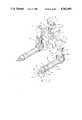
- each arm or major components thereof of the slave portionmay be readily removed and replaced as needed for maintenance and/or repair.
- FIGS. 6A and 6Bare partial cross-sectional drawings illustrating the hand and "fingers", i.e. the tongs, of the slave arm.
- a second gear box 126which receives input driving power from a motor 128.
- This motoris also provided with a position sensor (not shown), typically a potentiometer.
- the gear box 126 and motor 128are identical to the gear box 112 and motor 114.
- the gear boxhas an output ring 130 to which is releasably attached an upper arm mounting plate 132.
- Releasably attached to this mounting plateis an upper arm cover 134 as with bolts 136.
- the shoulder unit 32may be moved in a 240 degree circle around a horizontal axis, according to the motion 36 shown in FIG. 1, through the use of the motor 114 and the gear box 112.
- motion 40(see FIG. 1) is achieved through the use of motor 128 and gear box 126.
- This later motiontypically a 240 degrees rotation, is that provided for the upper arm 38 of the slave portion of the present invention.
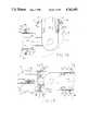
- FIG. 8a typical joint of the master portion of the manipulator, as shown generally in FIG. 2, is shown in detail in FIG. 8.
- this drawingshows the mechanism that typically exists at the wrist of the master unit as well as that that exists at the shoulder thereof.
- the master hand 256(element 98 of FIG. 2) is provided to be grasped by an operator.
- the hand unitis provided with one or more switches as indicated at 258, 260. The number and type of switch will depend upon the function of each.
- a mechanism for connecting the bevel gears to the potentiometeris a mechanism for connecting the bevel gears to the potentiometer. Typically this is accomplished through spur gears 290, 292. The latter of these gears is mounted on the shoulder 80 whereby the differential relationship between the upper arm and the shoulder will be determined.
- the signals derived from potentiometers 286, 288reflect the rotational relationship between the upper arm and the shoulder as well as the angular difference between the same.
Landscapes
- Engineering & Computer Science (AREA)
- Robotics (AREA)
- Mechanical Engineering (AREA)
- Multimedia (AREA)
- Manipulator (AREA)
Abstract
Description
Claims (18)
Priority Applications (1)
| Application Number | Priority Date | Filing Date | Title |
|---|---|---|---|
| US07/056,423US4762455A (en) | 1987-06-01 | 1987-06-01 | Remote manipulator |
Applications Claiming Priority (1)
| Application Number | Priority Date | Filing Date | Title |
|---|---|---|---|
| US07/056,423US4762455A (en) | 1987-06-01 | 1987-06-01 | Remote manipulator |
Publications (1)
| Publication Number | Publication Date |
|---|---|
| US4762455Atrue US4762455A (en) | 1988-08-09 |
Family
ID=22004313
Family Applications (1)
| Application Number | Title | Priority Date | Filing Date |
|---|---|---|---|
| US07/056,423Expired - Fee RelatedUS4762455A (en) | 1987-06-01 | 1987-06-01 | Remote manipulator |
Country Status (1)
| Country | Link |
|---|---|
| US (1) | US4762455A (en) |
Cited By (183)
| Publication number | Priority date | Publication date | Assignee | Title |
|---|---|---|---|---|
| US4889210A (en)* | 1988-05-31 | 1989-12-26 | Cofusa Enterprises, Inc. | Robotic product server and system |
| US4941106A (en)* | 1987-12-05 | 1990-07-10 | Noell Gmbh | Apparatus for recognizing and approaching a three-dimensional target |
| GB2228065A (en)* | 1989-01-20 | 1990-08-15 | Atomic Energy Authority Uk | Manual input device for controlling a robot arm |
| US5197346A (en)* | 1991-02-15 | 1993-03-30 | Comau S.P.A. | Articulated robot with two forearms |
| FR2683479A1 (en)* | 1991-11-07 | 1993-05-14 | Innovations Tech | Device for rotating and leaktight connection of a protective gaiter (boot, bellows) onto the end of a remote-manipulator slave arm |
| US5237468A (en)* | 1991-10-15 | 1993-08-17 | International Business Machines Corporation | Camera and gripper assembly for an automated storage library |
| US5243872A (en)* | 1990-04-30 | 1993-09-14 | Kumho & Co., Inc. | Robotic hand for controlling movement in multiple axes |
| US5249209A (en)* | 1989-07-07 | 1993-09-28 | Westinghouse Electric Corp. | Control rod canopy seal positioning and welding system |
| US5327354A (en)* | 1990-07-10 | 1994-07-05 | Daifuku Co., Ltd. | Control system for automatic warehousing facility |
| US5336982A (en)* | 1993-03-24 | 1994-08-09 | The United States Of America As Represented By The Administrator Of The National Aeronautics And Space Administration | Dual-arm generalized compliant motion with shared control |
| US5377950A (en)* | 1992-09-10 | 1995-01-03 | The University Of British Columbia | Platform mountings |
| US5408407A (en)* | 1993-03-15 | 1995-04-18 | Pentek, Inc. | System and method for positioning a work point |
| US5440476A (en)* | 1993-03-15 | 1995-08-08 | Pentek, Inc. | System for positioning a work point in three dimensional space |
| EP0776739A3 (en)* | 1992-01-21 | 1997-07-16 | Stanford Res Inst Int | |
| US5792135A (en)* | 1996-05-20 | 1998-08-11 | Intuitive Surgical, Inc. | Articulated surgical instrument for performing minimally invasive surgery with enhanced dexterity and sensitivity |
| US5807377A (en)* | 1996-05-20 | 1998-09-15 | Intuitive Surgical, Inc. | Force-reflecting surgical instrument and positioning mechanism for performing minimally invasive surgery with enhanced dexterity and sensitivity |
| US5810880A (en)* | 1995-06-07 | 1998-09-22 | Sri International | System and method for releasably holding a surgical instrument |
| US5814038A (en)* | 1995-06-07 | 1998-09-29 | Sri International | Surgical manipulator for a telerobotic system |
| US5931832A (en)* | 1993-05-14 | 1999-08-03 | Sri International | Methods for positioning a surgical instrument about a remote spherical center of rotation |
| EP0653922B1 (en)* | 1992-08-10 | 1999-12-15 | Computer Motion, Inc. | Automated endoscope system for optimal positioning |
| US6082290A (en)* | 1997-09-15 | 2000-07-04 | Conlin; Douglas | Paint spray booth with robot |
| US6346150B1 (en) | 1998-06-19 | 2002-02-12 | Douglas Conlin | Paint spray booth with robot |
| US20020082612A1 (en)* | 1998-11-20 | 2002-06-27 | Intuitive Surgical, Inc. | Arm cart for telerobotic surgical system |
| US6424885B1 (en) | 1999-04-07 | 2002-07-23 | Intuitive Surgical, Inc. | Camera referenced control in a minimally invasive surgical apparatus |
| US6436107B1 (en) | 1996-02-20 | 2002-08-20 | Computer Motion, Inc. | Method and apparatus for performing minimally invasive surgical procedures |
| US6459748B1 (en)* | 1999-11-08 | 2002-10-01 | Westinghouse Electric Company Llc | Floating ultrasonic testing end effector for a robotic arm |
| US6463361B1 (en) | 1994-09-22 | 2002-10-08 | Computer Motion, Inc. | Speech interface for an automated endoscopic system |
| US6646541B1 (en) | 1996-06-24 | 2003-11-11 | Computer Motion, Inc. | General purpose distributed operating room control system |
| US6676684B1 (en) | 2001-09-04 | 2004-01-13 | Intuitive Surgical, Inc. | Roll-pitch-roll-yaw surgical tool |
| US6685698B2 (en) | 2000-07-27 | 2004-02-03 | Intuitive Surgical, Inc. | Roll-pitch-roll surgical tool |
| US6699177B1 (en) | 1996-02-20 | 2004-03-02 | Computer Motion, Inc. | Method and apparatus for performing minimally invasive surgical procedures |
| US6714841B1 (en) | 1995-09-15 | 2004-03-30 | Computer Motion, Inc. | Head cursor control interface for an automated endoscope system for optimal positioning |
| US6726699B1 (en) | 2000-08-15 | 2004-04-27 | Computer Motion, Inc. | Instrument guide |
| US6728599B2 (en) | 2001-09-07 | 2004-04-27 | Computer Motion, Inc. | Modularity system for computer assisted surgery |
| US6731988B1 (en) | 1992-01-21 | 2004-05-04 | Sri International | System and method for remote endoscopic surgery |
| US6772053B2 (en) | 1998-12-08 | 2004-08-03 | Visx, Incorporated | Aspects of a control system of a minimally invasive surgical apparatus |
| US6788999B2 (en) | 1992-01-21 | 2004-09-07 | Sri International, Inc. | Surgical system |
| US6793653B2 (en) | 2001-12-08 | 2004-09-21 | Computer Motion, Inc. | Multifunctional handle for a medical robotic system |
| US20040186345A1 (en)* | 1996-02-20 | 2004-09-23 | Computer Motion, Inc. | Medical robotic arm that is attached to an operating table |
| US6804581B2 (en) | 1992-08-10 | 2004-10-12 | Computer Motion, Inc. | Automated endoscope system for optimal positioning |
| US6839612B2 (en) | 2001-12-07 | 2005-01-04 | Institute Surgical, Inc. | Microwrist system for surgical procedures |
| US6850817B1 (en) | 1992-01-21 | 2005-02-01 | Sri International | Surgical system |
| US6852107B2 (en) | 2002-01-16 | 2005-02-08 | Computer Motion, Inc. | Minimally invasive surgical training using robotics and tele-collaboration |
| US6858003B2 (en) | 1998-11-20 | 2005-02-22 | Intuitive Surgical, Inc. | Performing cardiac surgery without cardioplegia |
| US6902560B1 (en) | 2000-07-27 | 2005-06-07 | Intuitive Surgical, Inc. | Roll-pitch-roll surgical tool |
| US6905491B1 (en) | 1996-02-20 | 2005-06-14 | Intuitive Surgical, Inc. | Apparatus for performing minimally invasive cardiac procedures with a robotic arm that has a passive joint and system which can decouple the robotic arm from the input device |
| US6951535B2 (en) | 2002-01-16 | 2005-10-04 | Intuitive Surgical, Inc. | Tele-medicine system that transmits an entire state of a subsystem |
| US20050251110A1 (en)* | 2004-05-04 | 2005-11-10 | Intuitive Surgical, Inc. | Tool grip calibration for robotic surgery |
| US7053752B2 (en) | 1996-08-06 | 2006-05-30 | Intuitive Surgical | General purpose distributed operating room control system |
| US7074179B2 (en) | 1992-08-10 | 2006-07-11 | Intuitive Surgical Inc | Method and apparatus for performing minimally invasive cardiac procedures |
| US7217240B2 (en) | 1999-10-01 | 2007-05-15 | Intuitive Surgical, Inc. | Heart stabilizer |
| US7259652B2 (en) | 1996-08-06 | 2007-08-21 | Intuitive Surgical, Inc. | General purpose distributed operating room control system |
| US7259906B1 (en) | 2002-09-03 | 2007-08-21 | Cheetah Omni, Llc | System and method for voice control of medical devices |
| US20070279622A1 (en)* | 2004-02-27 | 2007-12-06 | Kazuhide Yamauchi | Multidirectional Simultaneous Observation Optical System, Image Reading Device, Image Reading Method, And Multidirectional Simultaneous Observation Combined Optical System |
| US20080109014A1 (en)* | 2006-11-06 | 2008-05-08 | De La Pena Alejandro Ramos | Robotic surgical device |
| KR100848170B1 (en) | 2007-03-30 | 2008-07-23 | 주식회사 피앤에스미캐닉스 | Dodge hand internal and external devices and dodge hand devices including the same |
| US7408439B2 (en) | 1996-06-24 | 2008-08-05 | Intuitive Surgical, Inc. | Method and apparatus for accessing medical data over a network |
| US20080227073A1 (en)* | 2005-09-29 | 2008-09-18 | Ryan Scott Bardsley | Methods and Apparatus for Autonomous Casualty Simulation |
| US20090104843A1 (en)* | 2007-10-19 | 2009-04-23 | Industrial Technology Research Institue | Position controlling mechanism and apparatus for controlling eye movement using the same |
| US20090204110A1 (en)* | 2005-11-18 | 2009-08-13 | Omni Sciences, Inc. | Broadband or Mid-Infrared Fiber Light Sources |
| US20100225036A1 (en)* | 2009-03-05 | 2010-09-09 | Shenzhen Futaihong Precision Industry Co., Ltd. | Adjustable fixture |
| US20100234857A1 (en)* | 1998-11-20 | 2010-09-16 | Intuitve Surgical Operations, Inc. | Medical robotic system with operatively couplable simulator unit for surgeon training |
| US7862580B2 (en) | 2002-12-06 | 2011-01-04 | Intuitive Surgical Operations, Inc. | Flexible wrist for surgical tool |
| US20110071671A1 (en)* | 2009-09-22 | 2011-03-24 | Gm Global Technology Operations, Inc. | Dexterous humanoid robotic wrist |
| EP2364824A1 (en)* | 2010-03-11 | 2011-09-14 | Motor Power Company S.r.l. | A device for moving objects and a machine comprising said device |
| US20110245844A1 (en)* | 2010-03-30 | 2011-10-06 | Terumo Kabushiki Kaisha | Medical robot system |
| US20120061155A1 (en)* | 2010-04-09 | 2012-03-15 | Willow Garage, Inc. | Humanoid robotics system and methods |
| ITTO20110159A1 (en)* | 2011-02-24 | 2012-08-25 | Comau Spa | ROBOT MANIPULATOR |
| WO2012149392A3 (en)* | 2011-04-29 | 2013-01-03 | Ratheon Company | Multi-degree of freedom torso support for a robotic agile lift system |
| US20130011220A1 (en)* | 2011-04-29 | 2013-01-10 | Raytheon Company | System and Method For Controlling A Teleoperated Robotic Agile Lift System |
| EP2574427A1 (en)* | 2011-09-30 | 2013-04-03 | Schunk GmbH & Co. KG Spann- und Greiftechnik | Handling module, in particular gripping, linear or rotary module and corresponding handling device |
| US8527094B2 (en) | 1998-11-20 | 2013-09-03 | Intuitive Surgical Operations, Inc. | Multi-user medical robotic system for collaboration or training in minimally invasive surgical procedures |
| US8617203B2 (en) | 2011-12-02 | 2013-12-31 | Ethicon Endo-Surgery, Inc. | Jaw assembly for surgical devices |
| US8641698B2 (en) | 2001-05-01 | 2014-02-04 | Intuitive Surgical Operations, Inc. | Pivot point arm for robotic system used to perform a surgical procedure |
| CN103624804A (en)* | 2012-08-27 | 2014-03-12 | 韩国原子力硏究院 | Remote attaching and detaching device including cell camera |
| US20140172171A1 (en)* | 2012-12-17 | 2014-06-19 | Hyundai Motor Company | Method for controlling two arms of a robot |
| US8828046B2 (en) | 2010-10-14 | 2014-09-09 | Ethicon Endo-Surgery, Inc. | Laparoscopic device with distal handle |
| US8843235B2 (en) | 2012-01-13 | 2014-09-23 | Toyota Motor Engineering & Manufacturing North America, Inc. | Robots, computer program products, and methods for trajectory plan optimization |
| US8845681B2 (en) | 1996-11-22 | 2014-09-30 | Intuitive Surgical Operations, Inc. | Rigidly-linked articulating wrist with decoupled motion transmission |
| US8870900B2 (en) | 1999-11-09 | 2014-10-28 | Intuitive Surgical Operations, Inc. | Endoscopic beating-heart stabilizer and vessel occlusion fastener |
| US8911428B2 (en) | 2001-06-29 | 2014-12-16 | Intuitive Surgical Operations, Inc. | Apparatus for pitch and yaw rotation |
| US20140366673A1 (en)* | 2013-06-14 | 2014-12-18 | Seiko Epson Corporation | Robot |
| US20140373662A1 (en)* | 2013-06-24 | 2014-12-25 | Kabushiki Kaisha Yaskawa Denki | Robot, method for producing robot, and covering |
| US8944070B2 (en) | 1999-04-07 | 2015-02-03 | Intuitive Surgical Operations, Inc. | Non-force reflecting method for providing tool force information to a user of a telesurgical system |
| US8977388B2 (en) | 2011-04-29 | 2015-03-10 | Sarcos Lc | Platform perturbation compensation |
| US9005112B2 (en) | 2001-06-29 | 2015-04-14 | Intuitive Surgical Operations, Inc. | Articulate and swapable endoscope for a surgical robot |
| US9014857B2 (en) | 2012-01-13 | 2015-04-21 | Toyota Motor Engineering & Manufacturing North America, Inc. | Methods and computer-program products for generating grasp patterns for use by a robot |
| US9014850B2 (en) | 2012-01-13 | 2015-04-21 | Toyota Motor Engineering & Manufacturing North America, Inc. | Methods and computer-program products for evaluating grasp patterns, and robots incorporating the same |
| US20150166208A1 (en)* | 2013-12-13 | 2015-06-18 | Kabushiki Kaisha Yaskawa Denki | Robot system, container opening method, and manufacturing method of object to be processed |
| FR3015334A1 (en)* | 2013-12-23 | 2015-06-26 | Electricite De France | ROTARY ANNULAR CONNECTOR FOR ENVELOPE FOR PROTECTING AN ARTICULATED ROBOT ARM |
| US9066736B2 (en) | 2010-01-07 | 2015-06-30 | Omni Medsci, Inc. | Laser-based method and system for selectively processing target tissue material in a patient and optical catheter assembly for use therein |
| US20150210410A1 (en)* | 2012-10-05 | 2015-07-30 | Kabushiki Kaisha Yaskawa Denki | Automatic preparation system |
| JP2015150684A (en)* | 2014-02-11 | 2015-08-24 | ジマティック エス.ピー.エーGIMATIC S.p.A., | Protection casing for robot gripper |
| US9119654B2 (en) | 1998-11-20 | 2015-09-01 | Intuitive Surgical Operations, Inc. | Stabilizer for robotic beating-heart surgery |
| US9131987B2 (en) | 2011-12-02 | 2015-09-15 | Ethicon Endo-Surgery, Inc. | Elbow assembly for surgical devices |
| US9138129B2 (en) | 2007-06-13 | 2015-09-22 | Intuitive Surgical Operations, Inc. | Method and system for moving a plurality of articulated instruments in tandem back towards an entry guide |
| US9164032B2 (en) | 2012-12-31 | 2015-10-20 | Omni Medsci, Inc. | Short-wave infrared super-continuum lasers for detecting counterfeit or illicit drugs and pharmaceutical process control |
| US9179927B2 (en) | 2011-12-02 | 2015-11-10 | Ethicon Endo-Surgery, Inc. | Surgical methods using a surgical device having a fixed angular orientation |
| US9186220B2 (en) | 2010-12-17 | 2015-11-17 | Ethicon Endo-Surgery, Inc. | Surgical system and methods for mimicked motion |
| US9211159B2 (en) | 2011-12-02 | 2015-12-15 | Ethicon Endo-Surgery, Inc. | Surgical devices with intracorporeal elbow joint |
| US9241770B2 (en) | 2011-09-30 | 2016-01-26 | Ethicon Endo-Surgery, Inc. | Methods and devices for remotely controlling movement of surgical tools |
| US9314921B2 (en) | 2011-03-17 | 2016-04-19 | Sarcos Lc | Robotic lift device with human interface operation |
| US9333042B2 (en) | 2007-06-13 | 2016-05-10 | Intuitive Surgical Operations, Inc. | Medical robotic system with coupled control modes |
| US9345387B2 (en) | 2006-06-13 | 2016-05-24 | Intuitive Surgical Operations, Inc. | Preventing instrument/tissue collisions |
| US20160151912A1 (en)* | 2014-03-13 | 2016-06-02 | Brain Corporation | Interface for use with trainable modular robotic apparatus |
| JP2016117142A (en)* | 2014-12-23 | 2016-06-30 | 日立建機株式会社 | Work machine |
| US9403566B2 (en) | 2011-03-17 | 2016-08-02 | Sarcos Lc | Robotic mobile low-profile transport vehicle |
| JP2016147351A (en)* | 2015-02-13 | 2016-08-18 | Ntn株式会社 | Articulated robot using link actuation device |
| JP2016147350A (en)* | 2015-02-13 | 2016-08-18 | Ntn株式会社 | Articulated robot using link actuation device |
| US9469034B2 (en) | 2007-06-13 | 2016-10-18 | Intuitive Surgical Operations, Inc. | Method and system for switching modes of a robotic system |
| US9492927B2 (en) | 2009-08-15 | 2016-11-15 | Intuitive Surgical Operations, Inc. | Application of force feedback on an input device to urge its operator to command an articulated instrument to a preferred pose |
| US9516996B2 (en) | 2008-06-27 | 2016-12-13 | Intuitive Surgical Operations, Inc. | Medical robotic system providing computer generated auxiliary views of a camera instrument for controlling the position and orienting of its tip |
| JP2017013167A (en)* | 2015-06-30 | 2017-01-19 | 株式会社デンソーウェーブ | Operation system for robot arm |
| CN106426229A (en)* | 2016-10-20 | 2017-02-22 | 济南舜风科技有限公司 | Virtual reality monitoring control system for line patrol robot and control method |
| US20170072573A1 (en)* | 2015-09-15 | 2017-03-16 | Fanuc Corporation | Robot provided with wrist including hollow movable element and having waterproof structure |
| US9616580B2 (en) | 2012-05-14 | 2017-04-11 | Sarcos Lc | End effector for a robotic arm |
| US9622826B2 (en) | 2010-02-12 | 2017-04-18 | Intuitive Surgical Operations, Inc. | Medical robotic system providing sensory feedback indicating a difference between a commanded state and a preferred pose of an articulated instrument |
| US20170119482A1 (en)* | 2012-05-01 | 2017-05-04 | Board of Regents of the University of Nabraska | Single Site Robotic Device and Related Systems and Methods |
| US9718190B2 (en) | 2006-06-29 | 2017-08-01 | Intuitive Surgical Operations, Inc. | Tool position and identification indicator displayed in a boundary area of a computer display screen |
| US9717563B2 (en) | 2008-06-27 | 2017-08-01 | Intuitive Surgical Operations, Inc. | Medical robotic system providing an auxilary view including range of motion limitations for articulatable instruments extending out of a distal end of an entry guide |
| US9789603B2 (en) | 2011-04-29 | 2017-10-17 | Sarcos Lc | Teleoperated robotic system |
| US9788909B2 (en) | 2006-06-29 | 2017-10-17 | Intuitive Surgical Operations, Inc | Synthetic representation of a surgical instrument |
| US9789608B2 (en) | 2006-06-29 | 2017-10-17 | Intuitive Surgical Operations, Inc. | Synthetic representation of a surgical robot |
| US20180009111A1 (en)* | 2016-07-06 | 2018-01-11 | Inventec Appliances (Pudong) Corporation | Multiaxial robot of multitasking |
| JP2018008373A (en)* | 2017-10-18 | 2018-01-18 | セイコーエプソン株式会社 | ROBOT, ROBOT CONTROL DEVICE, AND ROBOT CONTROL METHOD |
| US9873196B2 (en) | 2015-06-24 | 2018-01-23 | Brain Corporation | Bistatic object detection apparatus and methods |
| US9897584B2 (en) | 2012-12-31 | 2018-02-20 | Omni Medsci, Inc. | Short-wave infrared super-continuum lasers for natural gas leak detection, exploration, and other active remote sensing applications |
| US9956044B2 (en) | 2009-08-15 | 2018-05-01 | Intuitive Surgical Operations, Inc. | Controller assisted reconfiguration of an articulated instrument during movement into and out of an entry guide |
| US9987743B2 (en) | 2014-03-13 | 2018-06-05 | Brain Corporation | Trainable modular robotic apparatus and methods |
| US9993159B2 (en) | 2012-12-31 | 2018-06-12 | Omni Medsci, Inc. | Near-infrared super-continuum lasers for early detection of breast and other cancers |
| US10008017B2 (en) | 2006-06-29 | 2018-06-26 | Intuitive Surgical Operations, Inc. | Rendering tool information as graphic overlays on displayed images of tools |
| CN108518464A (en)* | 2018-05-22 | 2018-09-11 | 中国核电工程有限公司 | A kind of separable master slave manipulator stretching motion transmission system |
| US10136819B2 (en) | 2012-12-31 | 2018-11-27 | Omni Medsci, Inc. | Short-wave infrared super-continuum lasers and similar light sources for imaging applications |
| WO2019009290A1 (en)* | 2017-07-05 | 2019-01-10 | 川崎重工業株式会社 | Robot system and packaging system |
| US10213113B2 (en) | 2012-12-31 | 2019-02-26 | Omni Medsci, Inc. | Physiological measurement device using light emitting diodes |
| US10258425B2 (en) | 2008-06-27 | 2019-04-16 | Intuitive Surgical Operations, Inc. | Medical robotic system providing an auxiliary view of articulatable instruments extending out of a distal end of an entry guide |
| US20190226287A1 (en)* | 2017-05-11 | 2019-07-25 | National Oilwell Varco Norway As | System and method for placing pipe in and removing pipe from a finger rack |
| US20190240831A1 (en)* | 2018-02-05 | 2019-08-08 | Kimball Electronics Indiana, Inc. | Robot Having Vertically Oriented Articulated Arm Motion |
| JP2019198960A (en)* | 2019-08-22 | 2019-11-21 | Ntn株式会社 | Articulated robot using link operation device |
| US10507066B2 (en) | 2013-02-15 | 2019-12-17 | Intuitive Surgical Operations, Inc. | Providing information of tools by filtering image areas adjacent to or on displayed images of the tools |
| US20190383109A1 (en)* | 2018-06-15 | 2019-12-19 | Rus-Tec Engineering, Ltd. | Pipe Handling Apparatus |
| US10660526B2 (en) | 2012-12-31 | 2020-05-26 | Omni Medsci, Inc. | Near-infrared time-of-flight imaging using laser diodes with Bragg reflectors |
| US10745209B2 (en)* | 2016-07-04 | 2020-08-18 | Kawasaki Jukogyo Kabushiki Kaisha | Workpiece inverting device |
| US10766133B2 (en) | 2014-05-06 | 2020-09-08 | Sarcos Lc | Legged robotic device utilizing modifiable linkage mechanism |
| US10765537B2 (en) | 2016-11-11 | 2020-09-08 | Sarcos Corp. | Tunable actuator joint modules having energy recovering quasi-passive elastic actuators for use within a robotic system |
| US10791800B2 (en)* | 2016-06-06 | 2020-10-06 | Fuerst Group, Inc. | Systems and methods for automatic production of a cord structure |
| US10821614B2 (en) | 2016-11-11 | 2020-11-03 | Sarcos Corp. | Clutched joint modules having a quasi-passive elastic actuator for a robotic assembly |
| US10828767B2 (en) | 2016-11-11 | 2020-11-10 | Sarcos Corp. | Tunable actuator joint modules having energy recovering quasi-passive elastic actuators with internal valve arrangements |
| US10843330B2 (en) | 2017-12-07 | 2020-11-24 | Sarcos Corp. | Resistance-based joint constraint for a master robotic system |
| US10906191B2 (en) | 2018-12-31 | 2021-02-02 | Sarcos Corp. | Hybrid robotic end effector |
| US10919161B2 (en) | 2016-11-11 | 2021-02-16 | Sarcos Corp. | Clutched joint modules for a robotic system |
| US11241801B2 (en) | 2018-12-31 | 2022-02-08 | Sarcos Corp. | Robotic end effector with dorsally supported actuation mechanism |
| US11331809B2 (en) | 2017-12-18 | 2022-05-17 | Sarcos Corp. | Dynamically controlled robotic stiffening element |
| US11351675B2 (en) | 2018-12-31 | 2022-06-07 | Sarcos Corp. | Robotic end-effector having dynamic stiffening elements for conforming object interaction |
| WO2022179793A1 (en)* | 2021-02-24 | 2022-09-01 | Dürr Systems Ag | Protective covering for a robot hand axis |
| RU2785920C1 (en)* | 2021-12-02 | 2022-12-14 | Российская Федерация, от имени которой выступает Государственная корпорация по атомной энергии "Росатом" (Госкорпорация "Росатом") | In-chamber manipulator |
| US11717956B1 (en) | 2022-08-29 | 2023-08-08 | Sarcos Corp. | Robotic joint system with integrated safety |
| US11794345B2 (en) | 2020-12-31 | 2023-10-24 | Sarcos Corp. | Unified robotic vehicle systems and methods of control |
| US11826032B2 (en) | 2013-07-17 | 2023-11-28 | Virtual Incision Corporation | Robotic surgical devices, systems and related methods |
| US11826014B2 (en) | 2016-05-18 | 2023-11-28 | Virtual Incision Corporation | Robotic surgical devices, systems and related methods |
| US11826907B1 (en) | 2022-08-17 | 2023-11-28 | Sarcos Corp. | Robotic joint system with length adapter |
| US11832902B2 (en) | 2012-08-08 | 2023-12-05 | Virtual Incision Corporation | Robotic surgical devices, systems, and related methods |
| US11833676B2 (en) | 2020-12-07 | 2023-12-05 | Sarcos Corp. | Combining sensor output data to prevent unsafe operation of an exoskeleton |
| US11872090B2 (en) | 2015-08-03 | 2024-01-16 | Virtual Incision Corporation | Robotic surgical devices, systems, and related methods |
| US11897132B1 (en) | 2022-11-17 | 2024-02-13 | Sarcos Corp. | Systems and methods for redundant network communication in a robot |
| US11903658B2 (en) | 2019-01-07 | 2024-02-20 | Virtual Incision Corporation | Robotically assisted surgical system and related devices and methods |
| US11909576B2 (en) | 2011-07-11 | 2024-02-20 | Board Of Regents Of The University Of Nebraska | Robotic surgical devices, systems, and related methods |
| US11924023B1 (en) | 2022-11-17 | 2024-03-05 | Sarcos Corp. | Systems and methods for redundant network communication in a robot |
| US11950867B2 (en) | 2018-01-05 | 2024-04-09 | Board Of Regents Of The University Of Nebraska | Single-arm robotic device with compact joint design and related systems and methods |
| US11974824B2 (en) | 2017-09-27 | 2024-05-07 | Virtual Incision Corporation | Robotic surgical devices with tracking camera technology and related systems and methods |
| US12070282B2 (en) | 2013-03-14 | 2024-08-27 | Board Of Regents Of The University Of Nebraska | Methods, systems, and devices relating to force control surgical systems |
| US12096999B2 (en) | 2014-11-11 | 2024-09-24 | Board Of Regents Of The University Of Nebraska | Robotic device with compact joint design and related systems and methods |
| US12156710B2 (en) | 2011-10-03 | 2024-12-03 | Virtual Incision Corporation | Robotic surgical devices, systems and related methods |
| US12172298B2 (en) | 2022-11-04 | 2024-12-24 | Sarcos Corp. | Robotic end-effector having dynamic stiffening elements with resilient spacers for conforming object interaction |
| US20250043477A1 (en)* | 2022-05-24 | 2025-02-06 | Abb Schweiz Ag | Robot and method for sewing an object |
| US20250050505A1 (en)* | 2022-05-24 | 2025-02-13 | Abb Schweiz Ag | Robot and method for sewing an object |
| US12239396B2 (en) | 2008-06-27 | 2025-03-04 | Intuitive Surgical Operations, Inc. | Medical robotic system providing an auxiliary view including range of motion limitations for articulatable instruments extending out of a distal end of an entry guide |
| US12266040B2 (en) | 2009-03-31 | 2025-04-01 | Intuitive Surgical Operations, Inc. | Rendering tool information as graphic overlays on displayed images of tools |
| US12268475B2 (en) | 2012-12-31 | 2025-04-08 | Omni Medsci, Inc. | Wearable device for differential measurement on pulse rate and blood flow |
| US12274517B2 (en) | 2016-08-30 | 2025-04-15 | Board Of Regents Of The University Of Nebraska | Robotic device with compact joint design and an additional degree of freedom and related systems and methods |
| US12295680B2 (en) | 2012-08-08 | 2025-05-13 | Board Of Regents Of The University Of Nebraska | Robotic surgical devices, systems and related methods |
| US12357400B2 (en) | 2006-06-29 | 2025-07-15 | Intuitive Surgical Operations, Inc. | Synthetic representation of a surgical robot |
| US20250305197A1 (en)* | 2024-03-29 | 2025-10-02 | Inteva Products, Llc | Sewing cell adjustable feature |
Citations (15)
| Publication number | Priority date | Publication date | Assignee | Title |
|---|---|---|---|---|
| US2858947A (en)* | 1953-11-16 | 1958-11-04 | Garrett Corp | Remote control manipulating apparatus |
| US2978118A (en)* | 1959-11-03 | 1961-04-04 | Raymond C Goertz | Manipulator for slave robot |
| US3128887A (en)* | 1960-02-25 | 1964-04-14 | Mechanical manipulators for the displacement of | |
| US3164267A (en)* | 1961-03-27 | 1965-01-05 | Figure | |
| US3425569A (en)* | 1966-10-28 | 1969-02-04 | Central Research Lab Inc | Extended reach sealed manipulator |
| US3481494A (en)* | 1966-08-27 | 1969-12-02 | Hans Walischmiller | Remote operating device for work in inaccessible spaces |
| US3923166A (en)* | 1973-10-11 | 1975-12-02 | Nasa | Remote manipulator system |
| US4196049A (en)* | 1977-03-25 | 1980-04-01 | Westinghouse Electric Corp. | Segmented articulating manipulator arm for nuclear reactor vessel inspection apparatus |
| US4221516A (en)* | 1978-05-31 | 1980-09-09 | Central Research Laboratories, Inc. | Master-slave manipulator |
| US4298300A (en)* | 1978-09-29 | 1981-11-03 | La Calhene | Master-slave mechanical manipulator with homothetic displacements |
| US4370091A (en)* | 1979-07-18 | 1983-01-25 | Ateliers Et Chantiers De Bretagne | Remote manipulator arm |
| US4460302A (en)* | 1980-05-14 | 1984-07-17 | Commissariat A L'energie Atomique | Handling equipment comprising a telescopic supporting assembly carrying a motorized orientation support for at least one articulated slave arm |
| US4650388A (en)* | 1982-09-20 | 1987-03-17 | La Calhene S.A. | Disconnectable coupling device for a manipulator wrist |
| EP0218139A1 (en)* | 1985-09-20 | 1987-04-15 | Kabushiki Kaisha Meidensha | Manipulator shoulder mechanism |
| US4717303A (en)* | 1985-02-25 | 1988-01-05 | Kabushiki Kaisha Meidensha | Joint mechanism for manipulators |
- 1987
- 1987-06-01USUS07/056,423patent/US4762455A/ennot_activeExpired - Fee Related
Patent Citations (15)
| Publication number | Priority date | Publication date | Assignee | Title |
|---|---|---|---|---|
| US2858947A (en)* | 1953-11-16 | 1958-11-04 | Garrett Corp | Remote control manipulating apparatus |
| US2978118A (en)* | 1959-11-03 | 1961-04-04 | Raymond C Goertz | Manipulator for slave robot |
| US3128887A (en)* | 1960-02-25 | 1964-04-14 | Mechanical manipulators for the displacement of | |
| US3164267A (en)* | 1961-03-27 | 1965-01-05 | Figure | |
| US3481494A (en)* | 1966-08-27 | 1969-12-02 | Hans Walischmiller | Remote operating device for work in inaccessible spaces |
| US3425569A (en)* | 1966-10-28 | 1969-02-04 | Central Research Lab Inc | Extended reach sealed manipulator |
| US3923166A (en)* | 1973-10-11 | 1975-12-02 | Nasa | Remote manipulator system |
| US4196049A (en)* | 1977-03-25 | 1980-04-01 | Westinghouse Electric Corp. | Segmented articulating manipulator arm for nuclear reactor vessel inspection apparatus |
| US4221516A (en)* | 1978-05-31 | 1980-09-09 | Central Research Laboratories, Inc. | Master-slave manipulator |
| US4298300A (en)* | 1978-09-29 | 1981-11-03 | La Calhene | Master-slave mechanical manipulator with homothetic displacements |
| US4370091A (en)* | 1979-07-18 | 1983-01-25 | Ateliers Et Chantiers De Bretagne | Remote manipulator arm |
| US4460302A (en)* | 1980-05-14 | 1984-07-17 | Commissariat A L'energie Atomique | Handling equipment comprising a telescopic supporting assembly carrying a motorized orientation support for at least one articulated slave arm |
| US4650388A (en)* | 1982-09-20 | 1987-03-17 | La Calhene S.A. | Disconnectable coupling device for a manipulator wrist |
| US4717303A (en)* | 1985-02-25 | 1988-01-05 | Kabushiki Kaisha Meidensha | Joint mechanism for manipulators |
| EP0218139A1 (en)* | 1985-09-20 | 1987-04-15 | Kabushiki Kaisha Meidensha | Manipulator shoulder mechanism |
Non-Patent Citations (4)
| Title |
|---|
| "Evolving Toward Projected Man", Nuclear News, pp. 127-132, 6/82. |
| "FBR Fuel Cycle", NEI, p. 44, 2/87. |
| Evolving Toward Projected Man , Nuclear News, pp. 127 132, 6/82.* |
| FBR Fuel Cycle , NEI, p. 44, 2/87.* |
Cited By (440)
| Publication number | Priority date | Publication date | Assignee | Title |
|---|---|---|---|---|
| US4941106A (en)* | 1987-12-05 | 1990-07-10 | Noell Gmbh | Apparatus for recognizing and approaching a three-dimensional target |
| US4889210A (en)* | 1988-05-31 | 1989-12-26 | Cofusa Enterprises, Inc. | Robotic product server and system |
| GB2228065A (en)* | 1989-01-20 | 1990-08-15 | Atomic Energy Authority Uk | Manual input device for controlling a robot arm |
| GB2228065B (en)* | 1989-01-20 | 1992-10-28 | Atomic Energy Authority Uk | Manual controller |
| US5249209A (en)* | 1989-07-07 | 1993-09-28 | Westinghouse Electric Corp. | Control rod canopy seal positioning and welding system |
| US5243872A (en)* | 1990-04-30 | 1993-09-14 | Kumho & Co., Inc. | Robotic hand for controlling movement in multiple axes |
| US5327354A (en)* | 1990-07-10 | 1994-07-05 | Daifuku Co., Ltd. | Control system for automatic warehousing facility |
| US5197346A (en)* | 1991-02-15 | 1993-03-30 | Comau S.P.A. | Articulated robot with two forearms |
| US5237468A (en)* | 1991-10-15 | 1993-08-17 | International Business Machines Corporation | Camera and gripper assembly for an automated storage library |
| FR2683479A1 (en)* | 1991-11-07 | 1993-05-14 | Innovations Tech | Device for rotating and leaktight connection of a protective gaiter (boot, bellows) onto the end of a remote-manipulator slave arm |
| JP2009183733A (en)* | 1992-01-21 | 2009-08-20 | Sri Internatl | Minimally invasive surgery system |
| EP1356781A3 (en)* | 1992-01-21 | 2013-07-24 | SRI International | Teleoperation surgical system |
| US6788999B2 (en) | 1992-01-21 | 2004-09-07 | Sri International, Inc. | Surgical system |
| US7890211B2 (en) | 1992-01-21 | 2011-02-15 | Intuitive Surgical Operations, Inc. | Master-slave manipulator system and apparatus |
| EP0776739A3 (en)* | 1992-01-21 | 1997-07-16 | Stanford Res Inst Int | |
| US6731988B1 (en) | 1992-01-21 | 2004-05-04 | Sri International | System and method for remote endoscopic surgery |
| US5808665A (en)* | 1992-01-21 | 1998-09-15 | Sri International | Endoscopic surgical instrument and method for use |
| US7107124B2 (en) | 1992-01-21 | 2006-09-12 | Sri International | Roll-pitch-roll wrist methods for minimally invasive robotic surgery |
| US6850817B1 (en) | 1992-01-21 | 2005-02-01 | Sri International | Surgical system |
| US7248944B2 (en) | 1992-01-21 | 2007-07-24 | Institute Surgical, Inc | Roll-pitch-roll wrist methods for minimally invasive robotic surgery |
| US20050065658A1 (en)* | 1992-01-21 | 2005-03-24 | Sri International | Flexible robotic surgery system and method |
| US20050102062A1 (en)* | 1992-01-21 | 2005-05-12 | Sri International | Roll-pitch-roll wrist methods for minimally invasive robotic surgery |
| US6963792B1 (en) | 1992-01-21 | 2005-11-08 | Sri International | Surgical method |
| US6999852B2 (en) | 1992-01-21 | 2006-02-14 | Sri International | Flexible robotic surgery system and method |
| US20060142897A1 (en)* | 1992-01-21 | 2006-06-29 | Sri International | Roll-pitch-roll wrist methods for minimally invasive robotic surgery |
| US6223100B1 (en) | 1992-01-21 | 2001-04-24 | Sri, International | Apparatus and method for performing computer enhanced surgery with articulated instrument |
| US6804581B2 (en) | 1992-08-10 | 2004-10-12 | Computer Motion, Inc. | Automated endoscope system for optimal positioning |
| EP0653922B1 (en)* | 1992-08-10 | 1999-12-15 | Computer Motion, Inc. | Automated endoscope system for optimal positioning |
| US7074179B2 (en) | 1992-08-10 | 2006-07-11 | Intuitive Surgical Inc | Method and apparatus for performing minimally invasive cardiac procedures |
| US5377950A (en)* | 1992-09-10 | 1995-01-03 | The University Of British Columbia | Platform mountings |
| US5408407A (en)* | 1993-03-15 | 1995-04-18 | Pentek, Inc. | System and method for positioning a work point |
| US5440476A (en)* | 1993-03-15 | 1995-08-08 | Pentek, Inc. | System for positioning a work point in three dimensional space |
| US5336982A (en)* | 1993-03-24 | 1994-08-09 | The United States Of America As Represented By The Administrator Of The National Aeronautics And Space Administration | Dual-arm generalized compliant motion with shared control |
| US5931832A (en)* | 1993-05-14 | 1999-08-03 | Sri International | Methods for positioning a surgical instrument about a remote spherical center of rotation |
| US7395249B2 (en) | 1994-09-22 | 2008-07-01 | Intuitive Surgical, Inc. | Speech interface for an automated endoscope system |
| US6463361B1 (en) | 1994-09-22 | 2002-10-08 | Computer Motion, Inc. | Speech interface for an automated endoscopic system |
| US6965812B2 (en) | 1994-09-22 | 2005-11-15 | Computer Motion, Inc. | Speech interface for an automated endoscopic system |
| US5814038A (en)* | 1995-06-07 | 1998-09-29 | Sri International | Surgical manipulator for a telerobotic system |
| US7204844B2 (en) | 1995-06-07 | 2007-04-17 | Sri, International | System and method for releasably holding a surgical instrument |
| US7824424B2 (en) | 1995-06-07 | 2010-11-02 | Sri International | System and method for releasably holding a surgical instrument |
| US8500753B2 (en) | 1995-06-07 | 2013-08-06 | Sri International | Surgical manipulator for a telerobotic system |
| US8840628B2 (en) | 1995-06-07 | 2014-09-23 | Intuitive Surgical Operations, Inc. | Surgical manipulator for a telerobotic system |
| US7648513B2 (en) | 1995-06-07 | 2010-01-19 | Sri International | Surgical manipulator for a telerobotic system |
| US6461372B1 (en) | 1995-06-07 | 2002-10-08 | Sri International | System and method for releasably holding a surgical instrument |
| US20050273086A1 (en)* | 1995-06-07 | 2005-12-08 | Sri International | Surgical manipulator for a telerobotic system |
| US5810880A (en)* | 1995-06-07 | 1998-09-22 | Sri International | System and method for releasably holding a surgical instrument |
| US8048088B2 (en) | 1995-06-07 | 2011-11-01 | Sri International | Surgical manipulator for a telerobotic system |
| US6080181A (en)* | 1995-06-07 | 2000-06-27 | Sri International | System and method for releasably holding a surgical instrument |
| US8012160B2 (en) | 1995-06-07 | 2011-09-06 | Sri International | System and method for releasably holding a surgical instrument |
| US20100160930A1 (en)* | 1995-06-07 | 2010-06-24 | Sri International | Surgical manipulator for a telerobotic system |
| US6413264B1 (en) | 1995-06-07 | 2002-07-02 | Sri International | Surgical manipulator for a telerobotic system |
| US6620174B2 (en) | 1995-06-07 | 2003-09-16 | Sri International | Surgical manipulator for a telerobotic system |
| US6714841B1 (en) | 1995-09-15 | 2004-03-30 | Computer Motion, Inc. | Head cursor control interface for an automated endoscope system for optimal positioning |
| US6699177B1 (en) | 1996-02-20 | 2004-03-02 | Computer Motion, Inc. | Method and apparatus for performing minimally invasive surgical procedures |
| US7507199B2 (en) | 1996-02-20 | 2009-03-24 | Intuitive Surgical, Inc. | Method and apparatus for performing minimally invasive cardiac procedures |
| US7118582B1 (en) | 1996-02-20 | 2006-10-10 | Computer Motion, Inc. | Method and apparatus for performing minimally invasive cardiac procedures |
| US7083571B2 (en) | 1996-02-20 | 2006-08-01 | Intuitive Surgical | Medical robotic arm that is attached to an operating table |
| US7914521B2 (en) | 1996-02-20 | 2011-03-29 | Intuitive Surgical Operations, Inc. | Method and apparatus for performing minimally invasive cardiac procedures |
| US7695481B2 (en) | 1996-02-20 | 2010-04-13 | Intuitive Surgical, Inc. | Medical robotic system with different scaling factors |
| US6436107B1 (en) | 1996-02-20 | 2002-08-20 | Computer Motion, Inc. | Method and apparatus for performing minimally invasive surgical procedures |
| US6905491B1 (en) | 1996-02-20 | 2005-06-14 | Intuitive Surgical, Inc. | Apparatus for performing minimally invasive cardiac procedures with a robotic arm that has a passive joint and system which can decouple the robotic arm from the input device |
| US20080228196A1 (en)* | 1996-02-20 | 2008-09-18 | Intuitive Surgical, Inc. | Surgical robotic system for performing minimally invasive surgical procedures |
| US20040186345A1 (en)* | 1996-02-20 | 2004-09-23 | Computer Motion, Inc. | Medical robotic arm that is attached to an operating table |
| US8709000B2 (en) | 1996-05-20 | 2014-04-29 | Intuitive Surgical Operations, Inc. | Articulated surgical instrument for performing minimally invasive surgery with enhanced dexterity and sensitivity |
| US20060030841A1 (en)* | 1996-05-20 | 2006-02-09 | Madhani Akhil J | Articulated surgical instrument for performing minimally invasive surgery with enhanced dexterity and sensitivity |
| US5792135A (en)* | 1996-05-20 | 1998-08-11 | Intuitive Surgical, Inc. | Articulated surgical instrument for performing minimally invasive surgery with enhanced dexterity and sensitivity |
| US20100292708A1 (en)* | 1996-05-20 | 2010-11-18 | Intuitive Surgical Operations, Inc. | Articulated Surgical Instrument for Performing Minimally Invasive Surgery with Enhanced Dexterity and Sensitivity |
| US9510915B2 (en) | 1996-05-20 | 2016-12-06 | Intuitive Surgical Operations, Inc. | Articulated surgical instrument for performing minimally invasive surgery with enhanced dexterity and sensitivity |
| US5807377A (en)* | 1996-05-20 | 1998-09-15 | Intuitive Surgical, Inc. | Force-reflecting surgical instrument and positioning mechanism for performing minimally invasive surgery with enhanced dexterity and sensitivity |
| US8343141B2 (en) | 1996-05-20 | 2013-01-01 | Intuitive Surgical Operations, Inc. | Articulated surgical instrument for performing minimally invasive surgery with enhanced dexterity and sensitivity |
| US9999473B2 (en) | 1996-05-20 | 2018-06-19 | Intuitive Surgical Operations, Inc. | Articulated surgical instrument for performing minimally invasive surgery with enhanced dexterity and sensitivity |
| US20020103476A1 (en)* | 1996-05-20 | 2002-08-01 | Intuitive Surgical, Inc. | Articulated surgical instrument for performing minimally invasive surgery with enhanced dexterity and sensitivity |
| US20080077159A1 (en)* | 1996-05-20 | 2008-03-27 | Intuitive Surgical Inc. | Articulated surgical instrument for performing minimally invasive surgery with enhanced dexterity and sensitivity |
| US7780651B2 (en) | 1996-05-20 | 2010-08-24 | Intuitive Surgical Operations, Inc. | Articulated surgical instrument for performing minimally invasive surgery with enhanced dexterity and sensitivity |
| US6371952B1 (en) | 1996-05-20 | 2002-04-16 | Intuitive Surgical, Inc. | Articulated surgical instrument for performing minimally invasive surgery with enhanced dexterity and sensitivity |
| US6991627B2 (en) | 1996-05-20 | 2006-01-31 | Intuitive Surgical Inc. | Articulated surgical instrument for performing minimally invasive surgery with enhanced dexterity and sensitivity |
| US5976122A (en)* | 1996-05-20 | 1999-11-02 | Integrated Surgical Systems, Inc. | Articulated surgical instrument for performing minimally invasive surgery with enhanced dexterity and sensitivity |
| US7316681B2 (en) | 1996-05-20 | 2008-01-08 | Intuitive Surgical, Inc | Articulated surgical instrument for performing minimally invasive surgery with enhanced dexterity and sensitivity |
| US6646541B1 (en) | 1996-06-24 | 2003-11-11 | Computer Motion, Inc. | General purpose distributed operating room control system |
| US7097640B2 (en) | 1996-06-24 | 2006-08-29 | Intuitive Surgical, Inc. | Multi-functional surgical control system and switching interface |
| US7408439B2 (en) | 1996-06-24 | 2008-08-05 | Intuitive Surgical, Inc. | Method and apparatus for accessing medical data over a network |
| US7543588B2 (en) | 1996-06-24 | 2009-06-09 | Intuitive Surgical, Inc. | Multi-functional surgical control system switching interface |
| US7259652B2 (en) | 1996-08-06 | 2007-08-21 | Intuitive Surgical, Inc. | General purpose distributed operating room control system |
| US7053752B2 (en) | 1996-08-06 | 2006-05-30 | Intuitive Surgical | General purpose distributed operating room control system |
| US8845681B2 (en) | 1996-11-22 | 2014-09-30 | Intuitive Surgical Operations, Inc. | Rigidly-linked articulating wrist with decoupled motion transmission |
| US9402619B2 (en) | 1996-11-22 | 2016-08-02 | Intuitive Surgical Operation, Inc. | Rigidly-linked articulating wrist with decoupled motion transmission |
| US6082290A (en)* | 1997-09-15 | 2000-07-04 | Conlin; Douglas | Paint spray booth with robot |
| US6346150B1 (en) | 1998-06-19 | 2002-02-12 | Douglas Conlin | Paint spray booth with robot |
| US9867671B2 (en) | 1998-11-20 | 2018-01-16 | Intuitive Surgical Operations, Inc. | Multi-user medical robotic system for collaboration or training in minimally invasive surgical procedures |
| US8489235B2 (en) | 1998-11-20 | 2013-07-16 | Intuitive Surgical Operations, Inc. | Cooperative minimally invasive telesurgical system |
| US6837883B2 (en) | 1998-11-20 | 2005-01-04 | Intuitive Surgical, Inc. | Arm cart for telerobotic surgical system |
| US7865266B2 (en) | 1998-11-20 | 2011-01-04 | Intuitive Surgical Operations, Inc. | Cooperative minimally invasive telesurgical system |
| US8527094B2 (en) | 1998-11-20 | 2013-09-03 | Intuitive Surgical Operations, Inc. | Multi-user medical robotic system for collaboration or training in minimally invasive surgical procedures |
| US8504201B2 (en) | 1998-11-20 | 2013-08-06 | Intuitive Sugrical Operations, Inc. | Cooperative minimally invasive telesurgical system |
| US9636186B2 (en) | 1998-11-20 | 2017-05-02 | Intuitive Surgical Operations, Inc. | Multi-user medical robotic system for collaboration or training in minimally invasive surgical procedures |
| US9271798B2 (en) | 1998-11-20 | 2016-03-01 | Intuitive Surgical Operations, Inc. | Multi-user medical robotic system for collaboration or training in minimally invasive surgical procedures |
| US20100234857A1 (en)* | 1998-11-20 | 2010-09-16 | Intuitve Surgical Operations, Inc. | Medical robotic system with operatively couplable simulator unit for surgeon training |
| US8914150B2 (en) | 1998-11-20 | 2014-12-16 | Intuitive Surgical Operations, Inc. | Cooperative minimally invasive telesurgical system |
| US9119654B2 (en) | 1998-11-20 | 2015-09-01 | Intuitive Surgical Operations, Inc. | Stabilizer for robotic beating-heart surgery |
| US8600551B2 (en) | 1998-11-20 | 2013-12-03 | Intuitive Surgical Operations, Inc. | Medical robotic system with operatively couplable simulator unit for surgeon training |
| US9666101B2 (en) | 1998-11-20 | 2017-05-30 | Intuitive Surgical Operations, Inc. | Multi-user medical robotic system for collaboration or training in minimally invasive surgical procedures |
| US8666544B2 (en) | 1998-11-20 | 2014-03-04 | Intuitive Surgical Operations, Inc. | Cooperative minimally invasive telesurgical system |
| US6858003B2 (en) | 1998-11-20 | 2005-02-22 | Intuitive Surgical, Inc. | Performing cardiac surgery without cardioplegia |
| US6659939B2 (en) | 1998-11-20 | 2003-12-09 | Intuitive Surgical, Inc. | Cooperative minimally invasive telesurgical system |
| US20050107808A1 (en)* | 1998-11-20 | 2005-05-19 | Intuitive Surgical, Inc. | Performing cardiac surgery without cardioplegia |
| US20030216715A1 (en)* | 1998-11-20 | 2003-11-20 | Intuitive Surgical, Inc. | Cooperative minimally invasive telesurgical system |
| US20020082612A1 (en)* | 1998-11-20 | 2002-06-27 | Intuitive Surgical, Inc. | Arm cart for telerobotic surgical system |
| US6772053B2 (en) | 1998-12-08 | 2004-08-03 | Visx, Incorporated | Aspects of a control system of a minimally invasive surgical apparatus |
| US9101397B2 (en) | 1999-04-07 | 2015-08-11 | Intuitive Surgical Operations, Inc. | Real-time generation of three-dimensional ultrasound image using a two-dimensional ultrasound transducer in a robotic system |
| US6424885B1 (en) | 1999-04-07 | 2002-07-23 | Intuitive Surgical, Inc. | Camera referenced control in a minimally invasive surgical apparatus |
| US10271909B2 (en) | 1999-04-07 | 2019-04-30 | Intuitive Surgical Operations, Inc. | Display of computer generated image of an out-of-view portion of a medical device adjacent a real-time image of an in-view portion of the medical device |
| US9232984B2 (en) | 1999-04-07 | 2016-01-12 | Intuitive Surgical Operations, Inc. | Real-time generation of three-dimensional ultrasound image using a two-dimensional ultrasound transducer in a robotic system |
| US20040039485A1 (en)* | 1999-04-07 | 2004-02-26 | Intuitive Surgical, Inc. | Camera referenced control in a minimally invasive surgical apparatus |
| US20050027397A1 (en)* | 1999-04-07 | 2005-02-03 | Intuitive Surgical, Inc. | Aspects of a control system of a minimally invasive surgical apparatus |
| US8944070B2 (en) | 1999-04-07 | 2015-02-03 | Intuitive Surgical Operations, Inc. | Non-force reflecting method for providing tool force information to a user of a telesurgical system |
| US10433919B2 (en) | 1999-04-07 | 2019-10-08 | Intuitive Surgical Operations, Inc. | Non-force reflecting method for providing tool force information to a user of a telesurgical system |
| US20060106493A1 (en)* | 1999-04-07 | 2006-05-18 | Intuitive Surgical Inc. | Camera referenced control in a minimally invasive surgical apparatus |
| US7217240B2 (en) | 1999-10-01 | 2007-05-15 | Intuitive Surgical, Inc. | Heart stabilizer |
| US6459748B1 (en)* | 1999-11-08 | 2002-10-01 | Westinghouse Electric Company Llc | Floating ultrasonic testing end effector for a robotic arm |
| US8870900B2 (en) | 1999-11-09 | 2014-10-28 | Intuitive Surgical Operations, Inc. | Endoscopic beating-heart stabilizer and vessel occlusion fastener |
| US9173643B2 (en) | 2000-07-27 | 2015-11-03 | Intuitive Surgical Operations Inc. | Pitch-roll-yaw surgical tool |
| US6902560B1 (en) | 2000-07-27 | 2005-06-07 | Intuitive Surgical, Inc. | Roll-pitch-roll surgical tool |
| US10052155B2 (en) | 2000-07-27 | 2018-08-21 | Intuitive Surgical Operations, Inc. | Roll-pitch-roll surgical tool |
| US8528440B2 (en) | 2000-07-27 | 2013-09-10 | Intuitive Surgical Operations, Inc. | Method for minimally invasive surgery |
| US6685698B2 (en) | 2000-07-27 | 2004-02-03 | Intuitive Surgical, Inc. | Roll-pitch-roll surgical tool |
| US7398707B2 (en) | 2000-07-27 | 2008-07-15 | Intuitive Surgical Inc. | Roll-pitch-roll surgical tool |
| US6746443B1 (en) | 2000-07-27 | 2004-06-08 | Intuitive Surgical Inc. | Roll-pitch-roll surgical tool |
| US7914522B2 (en) | 2000-07-27 | 2011-03-29 | Intuitive Surgical Operations, Inc. | Roll-pitch-roll surgical tool |
| US20110213346A1 (en)* | 2000-07-27 | 2011-09-01 | Intuitive Surgical Operations, Inc. | Roll-pitch-roll surgical tool |
| US6726699B1 (en) | 2000-08-15 | 2004-04-27 | Computer Motion, Inc. | Instrument guide |
| US8641698B2 (en) | 2001-05-01 | 2014-02-04 | Intuitive Surgical Operations, Inc. | Pivot point arm for robotic system used to perform a surgical procedure |
| US9011415B2 (en) | 2001-05-01 | 2015-04-21 | Intuitive Surgical Operations, Inc. | Pivot point arm for a robotic system used to perform a surgical procedure |
| US11051794B2 (en) | 2001-06-29 | 2021-07-06 | Intuitive Surgical Operations, Inc. | Apparatus for pitch and yaw rotation |
| US9730572B2 (en) | 2001-06-29 | 2017-08-15 | Intuitive Surgical Operations, Inc. | Articulate and swappable endoscope for a surgical robot |
| US9717486B2 (en) | 2001-06-29 | 2017-08-01 | Intuitive Surgical Operations, Inc. | Apparatus for pitch and yaw rotation |
| US10105128B2 (en) | 2001-06-29 | 2018-10-23 | Intuitive Surgical Operations, Inc. | Apparatus for pitch and yaw rotation |
| US9005112B2 (en) | 2001-06-29 | 2015-04-14 | Intuitive Surgical Operations, Inc. | Articulate and swapable endoscope for a surgical robot |
| US8911428B2 (en) | 2001-06-29 | 2014-12-16 | Intuitive Surgical Operations, Inc. | Apparatus for pitch and yaw rotation |
| US10506920B2 (en) | 2001-06-29 | 2019-12-17 | Intuitive Surgical Operations, Inc. | Articulate and swappable endoscope for a surgical robot |
| US6676684B1 (en) | 2001-09-04 | 2004-01-13 | Intuitive Surgical, Inc. | Roll-pitch-roll-yaw surgical tool |
| US6892112B2 (en) | 2001-09-07 | 2005-05-10 | Computer Motion, Inc. | Modularity system for computer assisted surgery |
| US6836703B2 (en) | 2001-09-07 | 2004-12-28 | Computer Motion, Inc. | Modularity system for computer assisted surgery |
| US6871117B2 (en) | 2001-09-07 | 2005-03-22 | Intuitive Surgical, Inc. | Modularity system for computer assisted surgery |
| US6799088B2 (en) | 2001-09-07 | 2004-09-28 | Computer Motion, Inc. | Modularity system for computer assisted surgery |
| US6728599B2 (en) | 2001-09-07 | 2004-04-27 | Computer Motion, Inc. | Modularity system for computer assisted surgery |
| US6785593B2 (en) | 2001-09-07 | 2004-08-31 | Computer Motion, Inc. | Modularity system for computer assisted surgery |
| US7239940B2 (en) | 2001-09-07 | 2007-07-03 | Intuitive Surgical, Inc | Modularity system for computer assisted surgery |
| US6839612B2 (en) | 2001-12-07 | 2005-01-04 | Institute Surgical, Inc. | Microwrist system for surgical procedures |
| US8939891B2 (en) | 2001-12-08 | 2015-01-27 | Intuitive Surgical Operations, Inc. | Multifunctional handle for a medical robotic system |
| US8002767B2 (en) | 2001-12-08 | 2011-08-23 | Intuitive Surgical Operations, Inc. | Multifunctional handle for a medical robotic system |
| US6793653B2 (en) | 2001-12-08 | 2004-09-21 | Computer Motion, Inc. | Multifunctional handle for a medical robotic system |
| US6852107B2 (en) | 2002-01-16 | 2005-02-08 | Computer Motion, Inc. | Minimally invasive surgical training using robotics and tele-collaboration |
| US7682357B2 (en) | 2002-01-16 | 2010-03-23 | Intuitive Surgical, Inc. | Tele-medicine system that transmits an entire state of a subsystem |
| US9786203B2 (en) | 2002-01-16 | 2017-10-10 | Intuitive Surgical Operations, Inc. | Minimally invasive surgical training using robotics and telecollaboration |
| US6951535B2 (en) | 2002-01-16 | 2005-10-04 | Intuitive Surgical, Inc. | Tele-medicine system that transmits an entire state of a subsystem |
| US20060047365A1 (en)* | 2002-01-16 | 2006-03-02 | Modjtaba Ghodoussi | Tele-medicine system that transmits an entire state of a subsystem |
| US9039681B2 (en) | 2002-01-16 | 2015-05-26 | Intuitive Surgical Operations, Inc. | Minimally invasive surgical training using robotics and telecollaboration |
| US7413565B2 (en) | 2002-01-16 | 2008-08-19 | Intuitive Surgical, Inc. | Minimally invasive surgical training using robotics and telecollaboration |
| US7633673B1 (en) | 2002-09-03 | 2009-12-15 | Cheetah Omni, Llc | System and method for generating infrared light for use in medical procedures |
| US8098423B2 (en) | 2002-09-03 | 2012-01-17 | Cheetah Omni, Llc | System and method for voice control of medical devices |
| US8472108B2 (en) | 2002-09-03 | 2013-06-25 | Cheetah Omni, Llc | System and method for voice control of medical devices |
| US7259906B1 (en) | 2002-09-03 | 2007-08-21 | Cheetah Omni, Llc | System and method for voice control of medical devices |
| US9055868B2 (en) | 2002-09-03 | 2015-06-16 | Omni Medsci, Inc. | System and method for voice control of medical devices |
| US9770174B2 (en) | 2002-09-03 | 2017-09-26 | Omni Medsci, Inc. | System and method for voice control of measurement apparatus |
| US7433116B1 (en) | 2002-09-03 | 2008-10-07 | Cheetah Omni, Llc | Infra-red light source including a raman shifter |
| US9456751B2 (en) | 2002-09-03 | 2016-10-04 | Omni Medsci, Inc. | System and method for voice control of medical devices |
| US8679011B2 (en) | 2002-09-03 | 2014-03-25 | Omni Medsci, Inc. | System and method for voice control of medical devices |
| US20100069723A1 (en)* | 2002-09-03 | 2010-03-18 | Cheetah Omni, Llc | System and Method for Voice Control of Medical Devices |
| US8848282B2 (en) | 2002-09-03 | 2014-09-30 | Omni Medsci, Inc. | System and method for voice control of medical devices |
| US9456750B2 (en) | 2002-09-03 | 2016-10-04 | Omni Medsci, Inc. | System and method for voice control of medical devices |
| US20110175989A1 (en)* | 2002-09-03 | 2011-07-21 | Cheetah Omni, Llc | System and method for voice control of medical devices |
| US10004402B2 (en) | 2002-09-03 | 2018-06-26 | Omni Medsci, Inc. | Measurement apparatus for physiological parameters |
| US8690908B2 (en) | 2002-12-06 | 2014-04-08 | Intuitive Surgical Operations, Inc. | Flexible wrist for surgical tool |
| US11633241B2 (en) | 2002-12-06 | 2023-04-25 | Intuitive Surgical Operations, Inc. | Flexible wrist for surgical tool |
| US8790243B2 (en) | 2002-12-06 | 2014-07-29 | Intuitive Surgical Operations, Inc. | Flexible wrist for surgical tool |
| US9585641B2 (en) | 2002-12-06 | 2017-03-07 | Intuitive Surgical Operations, Inc. | Flexible wrist for surgical tool |
| US7862580B2 (en) | 2002-12-06 | 2011-01-04 | Intuitive Surgical Operations, Inc. | Flexible wrist for surgical tool |
| US9623563B2 (en) | 2002-12-06 | 2017-04-18 | Intuitive Surgical Operations, Inc. | Tool grip calibration for robotic surgery |
| US10524868B2 (en) | 2002-12-06 | 2020-01-07 | Intuitive Surgical Operations, Inc. | Flexible wrist for surgical tool |
| US8337521B2 (en) | 2002-12-06 | 2012-12-25 | Intuitive Surgical Operations, Inc. | Flexible wrist for surgical tool |
| US9095317B2 (en) | 2002-12-06 | 2015-08-04 | Intuitive Surgical Operations, Inc. | Flexible wrist for surgical tool |
| US20070279622A1 (en)* | 2004-02-27 | 2007-12-06 | Kazuhide Yamauchi | Multidirectional Simultaneous Observation Optical System, Image Reading Device, Image Reading Method, And Multidirectional Simultaneous Observation Combined Optical System |
| US20050251110A1 (en)* | 2004-05-04 | 2005-11-10 | Intuitive Surgical, Inc. | Tool grip calibration for robotic surgery |
| US20080114494A1 (en)* | 2004-05-04 | 2008-05-15 | Intuitive Surgical, Inc. | Tool grip calibration for robotic surgery |
| US7386365B2 (en) | 2004-05-04 | 2008-06-10 | Intuitive Surgical, Inc. | Tool grip calibration for robotic surgery |
| US9317651B2 (en) | 2004-05-04 | 2016-04-19 | Intuitive Surgical Operations, Inc. | Tool grip calibration for robotic surgery |
| US9085083B2 (en) | 2004-05-04 | 2015-07-21 | Intuitive Surgical Operations, Inc. | Tool grip calibration for robotic surgery |
| US8452447B2 (en) | 2004-05-04 | 2013-05-28 | Intuitive Surgical Operations, Inc. | Tool grip calibration for robotic surgery |
| US10595946B2 (en) | 2004-05-04 | 2020-03-24 | Intuitive Surgical Operations, Inc. | Tool grip calibration for robotic surgery |
| US9872737B2 (en) | 2004-05-04 | 2018-01-23 | Intuitive Surgical Operations, Inc. | Tool grip calibration for robotic surgery |
| US20080227073A1 (en)* | 2005-09-29 | 2008-09-18 | Ryan Scott Bardsley | Methods and Apparatus for Autonomous Casualty Simulation |
| US20090204110A1 (en)* | 2005-11-18 | 2009-08-13 | Omni Sciences, Inc. | Broadband or Mid-Infrared Fiber Light Sources |
| US8971681B2 (en) | 2005-11-18 | 2015-03-03 | Omni Medsci, Inc. | Broadband or mid-infrared fiber light sources |
| US10942064B2 (en) | 2005-11-18 | 2021-03-09 | Omni Medsci, Inc. | Diagnostic system with broadband light source |
| US8670642B2 (en) | 2005-11-18 | 2014-03-11 | Omni Medsci, Inc. | Broadband or mid-infrared fiber light sources |
| US8055108B2 (en) | 2005-11-18 | 2011-11-08 | Cheetah Omni, L.L.C. | Broadband or mid-infrared fiber light sources |
| US9476769B2 (en) | 2005-11-18 | 2016-10-25 | Omni Medsci, Inc. | Broadband or mid-infrared fiber light sources |
| US9726539B2 (en) | 2005-11-18 | 2017-08-08 | Omni Medsci, Inc. | Broadband or mid-infrared fiber light sources |
| US8391660B2 (en) | 2005-11-18 | 2013-03-05 | Cheetah Omni, L.L.C. | Broadband or mid-infrared fiber light sources |
| US10041832B2 (en) | 2005-11-18 | 2018-08-07 | Omni Medsci, Inc. | Mid-infrared super-continuum laser |
| US9400215B2 (en) | 2005-11-18 | 2016-07-26 | Omni Medsci, Inc. | Broadband or mid-infrared fiber light sources |
| US9077146B2 (en) | 2005-11-18 | 2015-07-07 | Omni Medsci, Inc. | Broadband or mid-infrared fiber light sources |
| US10466102B2 (en) | 2005-11-18 | 2019-11-05 | Omni Medsci, Inc. | Spectroscopy system with laser and pulsed output beam |
| US9345387B2 (en) | 2006-06-13 | 2016-05-24 | Intuitive Surgical Operations, Inc. | Preventing instrument/tissue collisions |
| US9718190B2 (en) | 2006-06-29 | 2017-08-01 | Intuitive Surgical Operations, Inc. | Tool position and identification indicator displayed in a boundary area of a computer display screen |
| US9801690B2 (en) | 2006-06-29 | 2017-10-31 | Intuitive Surgical Operations, Inc. | Synthetic representation of a surgical instrument |
| US10008017B2 (en) | 2006-06-29 | 2018-06-26 | Intuitive Surgical Operations, Inc. | Rendering tool information as graphic overlays on displayed images of tools |
| US9788909B2 (en) | 2006-06-29 | 2017-10-17 | Intuitive Surgical Operations, Inc | Synthetic representation of a surgical instrument |
| US11865729B2 (en) | 2006-06-29 | 2024-01-09 | Intuitive Surgical Operations, Inc. | Tool position and identification indicator displayed in a boundary area of a computer display screen |
| US11638999B2 (en) | 2006-06-29 | 2023-05-02 | Intuitive Surgical Operations, Inc. | Synthetic representation of a surgical robot |
| US10137575B2 (en) | 2006-06-29 | 2018-11-27 | Intuitive Surgical Operations, Inc. | Synthetic representation of a surgical robot |
| US9789608B2 (en) | 2006-06-29 | 2017-10-17 | Intuitive Surgical Operations, Inc. | Synthetic representation of a surgical robot |
| US12357400B2 (en) | 2006-06-29 | 2025-07-15 | Intuitive Surgical Operations, Inc. | Synthetic representation of a surgical robot |
| US10773388B2 (en) | 2006-06-29 | 2020-09-15 | Intuitive Surgical Operations, Inc. | Tool position and identification indicator displayed in a boundary area of a computer display screen |
| US10737394B2 (en) | 2006-06-29 | 2020-08-11 | Intuitive Surgical Operations, Inc. | Synthetic representation of a surgical robot |
| US10730187B2 (en) | 2006-06-29 | 2020-08-04 | Intuitive Surgical Operations, Inc. | Tool position and identification indicator displayed in a boundary area of a computer display screen |
| US20080109014A1 (en)* | 2006-11-06 | 2008-05-08 | De La Pena Alejandro Ramos | Robotic surgical device |
| US20090143787A9 (en)* | 2006-11-06 | 2009-06-04 | De La Pena Alejandro Ramos | Robotic surgical device |
| US8551114B2 (en)* | 2006-11-06 | 2013-10-08 | Human Robotics S.A. De C.V. | Robotic surgical device |
| KR100848170B1 (en) | 2007-03-30 | 2008-07-23 | 주식회사 피앤에스미캐닉스 | Dodge hand internal and external devices and dodge hand devices including the same |
| US12097002B2 (en) | 2007-06-13 | 2024-09-24 | Intuitive Surgical Operations, Inc. | Medical robotic system with coupled control modes |
| US9469034B2 (en) | 2007-06-13 | 2016-10-18 | Intuitive Surgical Operations, Inc. | Method and system for switching modes of a robotic system |
| US12295681B2 (en) | 2007-06-13 | 2025-05-13 | Intuitive Surgical Operations, Inc. | Method and system for retracting an instrument into an entry guide |
| US10271912B2 (en) | 2007-06-13 | 2019-04-30 | Intuitive Surgical Operations, Inc. | Method and system for moving a plurality of articulated instruments in tandem back towards an entry guide |
| US9629520B2 (en) | 2007-06-13 | 2017-04-25 | Intuitive Surgical Operations, Inc. | Method and system for moving an articulated instrument back towards an entry guide while automatically reconfiguring the articulated instrument for retraction into the entry guide |
| US10188472B2 (en) | 2007-06-13 | 2019-01-29 | Intuitive Surgical Operations, Inc. | Medical robotic system with coupled control modes |
| US9333042B2 (en) | 2007-06-13 | 2016-05-10 | Intuitive Surgical Operations, Inc. | Medical robotic system with coupled control modes |
| US11751955B2 (en) | 2007-06-13 | 2023-09-12 | Intuitive Surgical Operations, Inc. | Method and system for retracting an instrument into an entry guide |
| US10695136B2 (en) | 2007-06-13 | 2020-06-30 | Intuitive Surgical Operations, Inc. | Preventing instrument/tissue collisions |
| US9138129B2 (en) | 2007-06-13 | 2015-09-22 | Intuitive Surgical Operations, Inc. | Method and system for moving a plurality of articulated instruments in tandem back towards an entry guide |
| US9901408B2 (en) | 2007-06-13 | 2018-02-27 | Intuitive Surgical Operations, Inc. | Preventing instrument/tissue collisions |
| US11399908B2 (en) | 2007-06-13 | 2022-08-02 | Intuitive Surgical Operations, Inc. | Medical robotic system with coupled control modes |
| US11432888B2 (en) | 2007-06-13 | 2022-09-06 | Intuitive Surgical Operations, Inc. | Method and system for moving a plurality of articulated instruments in tandem back towards an entry guide |
| US20090104843A1 (en)* | 2007-10-19 | 2009-04-23 | Industrial Technology Research Institue | Position controlling mechanism and apparatus for controlling eye movement using the same |
| US11638622B2 (en) | 2008-06-27 | 2023-05-02 | Intuitive Surgical Operations, Inc. | Medical robotic system providing an auxiliary view of articulatable instruments extending out of a distal end of an entry guide |
| US11382702B2 (en) | 2008-06-27 | 2022-07-12 | Intuitive Surgical Operations, Inc. | Medical robotic system providing an auxiliary view including range of motion limitations for articulatable instruments extending out of a distal end of an entry guide |
| US9516996B2 (en) | 2008-06-27 | 2016-12-13 | Intuitive Surgical Operations, Inc. | Medical robotic system providing computer generated auxiliary views of a camera instrument for controlling the position and orienting of its tip |
| US10368952B2 (en) | 2008-06-27 | 2019-08-06 | Intuitive Surgical Operations, Inc. | Medical robotic system providing an auxiliary view including range of motion limitations for articulatable instruments extending out of a distal end of an entry guide |
| US12239396B2 (en) | 2008-06-27 | 2025-03-04 | Intuitive Surgical Operations, Inc. | Medical robotic system providing an auxiliary view including range of motion limitations for articulatable instruments extending out of a distal end of an entry guide |
| US9717563B2 (en) | 2008-06-27 | 2017-08-01 | Intuitive Surgical Operations, Inc. | Medical robotic system providing an auxilary view including range of motion limitations for articulatable instruments extending out of a distal end of an entry guide |
| US10258425B2 (en) | 2008-06-27 | 2019-04-16 | Intuitive Surgical Operations, Inc. | Medical robotic system providing an auxiliary view of articulatable instruments extending out of a distal end of an entry guide |
| US8403312B2 (en)* | 2009-03-05 | 2013-03-26 | Shenzhen Futaihong Precision Industry Co., Ltd. | Adjustable fixture |
| US20100225036A1 (en)* | 2009-03-05 | 2010-09-09 | Shenzhen Futaihong Precision Industry Co., Ltd. | Adjustable fixture |
| US10984567B2 (en) | 2009-03-31 | 2021-04-20 | Intuitive Surgical Operations, Inc. | Rendering tool information as graphic overlays on displayed images of tools |
| US12266040B2 (en) | 2009-03-31 | 2025-04-01 | Intuitive Surgical Operations, Inc. | Rendering tool information as graphic overlays on displayed images of tools |
| US10282881B2 (en) | 2009-03-31 | 2019-05-07 | Intuitive Surgical Operations, Inc. | Rendering tool information as graphic overlays on displayed images of tools |
| US11941734B2 (en) | 2009-03-31 | 2024-03-26 | Intuitive Surgical Operations, Inc. | Rendering tool information as graphic overlays on displayed images of tools |
| US10271915B2 (en) | 2009-08-15 | 2019-04-30 | Intuitive Surgical Operations, Inc. | Application of force feedback on an input device to urge its operator to command an articulated instrument to a preferred pose |
| US9956044B2 (en) | 2009-08-15 | 2018-05-01 | Intuitive Surgical Operations, Inc. | Controller assisted reconfiguration of an articulated instrument during movement into and out of an entry guide |
| US10959798B2 (en) | 2009-08-15 | 2021-03-30 | Intuitive Surgical Operations, Inc. | Application of force feedback on an input device to urge its operator to command an articulated instrument to a preferred pose |
| US10772689B2 (en) | 2009-08-15 | 2020-09-15 | Intuitive Surgical Operations, Inc. | Controller assisted reconfiguration of an articulated instrument during movement into and out of an entry guide |
| US11596490B2 (en) | 2009-08-15 | 2023-03-07 | Intuitive Surgical Operations, Inc. | Application of force feedback on an input device to urge its operator to command an articulated instrument to a preferred pose |
| US9492927B2 (en) | 2009-08-15 | 2016-11-15 | Intuitive Surgical Operations, Inc. | Application of force feedback on an input device to urge its operator to command an articulated instrument to a preferred pose |
| US20110071671A1 (en)* | 2009-09-22 | 2011-03-24 | Gm Global Technology Operations, Inc. | Dexterous humanoid robotic wrist |
| US8498741B2 (en) | 2009-09-22 | 2013-07-30 | Gm Global Technology Operations | Dexterous humanoid robotic wrist |
| US10271904B2 (en) | 2010-01-07 | 2019-04-30 | Omni Medsci, Inc. | Laser-based method and system for selectively processing target tissue material in a patient and optical catheter assembly for use therein |
| US9066736B2 (en) | 2010-01-07 | 2015-06-30 | Omni Medsci, Inc. | Laser-based method and system for selectively processing target tissue material in a patient and optical catheter assembly for use therein |
| US9622826B2 (en) | 2010-02-12 | 2017-04-18 | Intuitive Surgical Operations, Inc. | Medical robotic system providing sensory feedback indicating a difference between a commanded state and a preferred pose of an articulated instrument |
| US10537994B2 (en) | 2010-02-12 | 2020-01-21 | Intuitive Surgical Operations, Inc. | Medical robotic system providing sensory feedback indicating a difference between a commanded state and a preferred pose of an articulated instrument |
| US10828774B2 (en) | 2010-02-12 | 2020-11-10 | Intuitive Surgical Operations, Inc. | Medical robotic system providing sensory feedback indicating a difference between a commanded state and a preferred pose of an articulated instrument |
| EP2364824A1 (en)* | 2010-03-11 | 2011-09-14 | Motor Power Company S.r.l. | A device for moving objects and a machine comprising said device |
| US9179979B2 (en)* | 2010-03-30 | 2015-11-10 | Karl Storz Gmbh & Co. Kg | Medical robot system |
| US20110245844A1 (en)* | 2010-03-30 | 2011-10-06 | Terumo Kabushiki Kaisha | Medical robot system |
| US20120061155A1 (en)* | 2010-04-09 | 2012-03-15 | Willow Garage, Inc. | Humanoid robotics system and methods |
| US20200047329A1 (en)* | 2010-04-09 | 2020-02-13 | Willow Garage, Inc. | Humanoid robotics system and methods |
| US10850386B2 (en) | 2010-04-09 | 2020-12-01 | Willow Garage, Llc | Humanoid robotics system and methods |
| US12403584B2 (en) | 2010-04-09 | 2025-09-02 | Willow Garage, Llc | Humanoid robotics system and methods |
| US11396096B2 (en) | 2010-04-09 | 2022-07-26 | Willow Garage, Llc | Humanoid robotics system and methods |
| US8828046B2 (en) | 2010-10-14 | 2014-09-09 | Ethicon Endo-Surgery, Inc. | Laparoscopic device with distal handle |
| US9186220B2 (en) | 2010-12-17 | 2015-11-17 | Ethicon Endo-Surgery, Inc. | Surgical system and methods for mimicked motion |
| US10856943B2 (en) | 2010-12-17 | 2020-12-08 | Ethicon Llc | Surgical system and methods for mimicked motion |
| US9186219B2 (en) | 2010-12-17 | 2015-11-17 | Ethicon Endo-Surgery, Inc. | Surgical system and methods for mimicked motion |
| US9937008B2 (en) | 2010-12-17 | 2018-04-10 | Ethicon Endo-Surgery, Llc | Surgical system and methods for mimicked motion |
| US8978506B2 (en) | 2011-02-24 | 2015-03-17 | Comau S.P.A. | Manipulator robot |
| ITTO20110159A1 (en)* | 2011-02-24 | 2012-08-25 | Comau Spa | ROBOT MANIPULATOR |
| RU2579712C2 (en)* | 2011-02-24 | 2016-04-10 | Комау С.п.А. | Robot-manipulator |
| CN102649269A (en)* | 2011-02-24 | 2012-08-29 | 康茂股份公司 | Manipulator robot |
| CN102649269B (en)* | 2011-02-24 | 2015-12-02 | 康茂股份公司 | Operator robot |
| EP2492056A1 (en)* | 2011-02-24 | 2012-08-29 | COMAU S.p.A. | Manipulator robot |
| US9403566B2 (en) | 2011-03-17 | 2016-08-02 | Sarcos Lc | Robotic mobile low-profile transport vehicle |
| US9314921B2 (en) | 2011-03-17 | 2016-04-19 | Sarcos Lc | Robotic lift device with human interface operation |
| US9919753B2 (en) | 2011-03-17 | 2018-03-20 | Sarcos Lc | Robotic mobile low-profile transport vehicle |
| US11738446B2 (en) | 2011-04-29 | 2023-08-29 | Sarcos, Lc | Teleoperated robotic system with impact responsive force feedback |
| US8977398B2 (en) | 2011-04-29 | 2015-03-10 | Sarcos Lc | Multi-degree of freedom torso support for a robotic agile lift system |
| US11745331B2 (en) | 2011-04-29 | 2023-09-05 | Sarcos, Lc | Teleoperated robotic system with payload stabilization |
| WO2012149392A3 (en)* | 2011-04-29 | 2013-01-03 | Ratheon Company | Multi-degree of freedom torso support for a robotic agile lift system |
| US8892258B2 (en) | 2011-04-29 | 2014-11-18 | Raytheon Company | Variable strength magnetic end effector for lift systems |
| US11865705B2 (en) | 2011-04-29 | 2024-01-09 | Sarcos, Lc | Teleoperated robotic system |
| US20150142172A1 (en)* | 2011-04-29 | 2015-05-21 | Sarcos Lc | System and Method for Controlling a Teleoperated Robotic Agile Lift System |
| US8977388B2 (en) | 2011-04-29 | 2015-03-10 | Sarcos Lc | Platform perturbation compensation |
| US9533411B2 (en)* | 2011-04-29 | 2017-01-03 | Sarcos Lc | System and method for controlling a teleoperated robotic agile lift system |
| US9789603B2 (en) | 2011-04-29 | 2017-10-17 | Sarcos Lc | Teleoperated robotic system |
| US20130011220A1 (en)* | 2011-04-29 | 2013-01-10 | Raytheon Company | System and Method For Controlling A Teleoperated Robotic Agile Lift System |
| US8942846B2 (en)* | 2011-04-29 | 2015-01-27 | Raytheon Company | System and method for controlling a teleoperated robotic agile lift system |
| US11909576B2 (en) | 2011-07-11 | 2024-02-20 | Board Of Regents Of The University Of Nebraska | Robotic surgical devices, systems, and related methods |
| US12323289B2 (en) | 2011-07-11 | 2025-06-03 | Board Of Regents Of The University Of Nebraska | Robotic surgical devices, systems, and related methods |
| EP2574427A1 (en)* | 2011-09-30 | 2013-04-03 | Schunk GmbH & Co. KG Spann- und Greiftechnik | Handling module, in particular gripping, linear or rotary module and corresponding handling device |
| US9956051B2 (en) | 2011-09-30 | 2018-05-01 | Ethicon Endo-Surgery, Inc. | Methods and devices for remotely controlling movement of surgical tools |
| US9241770B2 (en) | 2011-09-30 | 2016-01-26 | Ethicon Endo-Surgery, Inc. | Methods and devices for remotely controlling movement of surgical tools |
| US12156710B2 (en) | 2011-10-03 | 2024-12-03 | Virtual Incision Corporation | Robotic surgical devices, systems and related methods |
| US9179927B2 (en) | 2011-12-02 | 2015-11-10 | Ethicon Endo-Surgery, Inc. | Surgical methods using a surgical device having a fixed angular orientation |
| US9211159B2 (en) | 2011-12-02 | 2015-12-15 | Ethicon Endo-Surgery, Inc. | Surgical devices with intracorporeal elbow joint |
| US9955988B2 (en) | 2011-12-02 | 2018-05-01 | Ethicon Endo-Surgery, Llc | Surgical devices with intracorporeal elbow joint |
| US9131987B2 (en) | 2011-12-02 | 2015-09-15 | Ethicon Endo-Surgery, Inc. | Elbow assembly for surgical devices |
| US10918404B2 (en) | 2011-12-02 | 2021-02-16 | Ethicon Llc | Surgical devices with intracorporeal elbow joint |
| US8617203B2 (en) | 2011-12-02 | 2013-12-31 | Ethicon Endo-Surgery, Inc. | Jaw assembly for surgical devices |
| US9375839B2 (en) | 2012-01-13 | 2016-06-28 | Carnegie Mellon University | Methods and computer-program products for evaluating grasp patterns, and robots incorporating the same |
| US9014857B2 (en) | 2012-01-13 | 2015-04-21 | Toyota Motor Engineering & Manufacturing North America, Inc. | Methods and computer-program products for generating grasp patterns for use by a robot |
| US9014850B2 (en) | 2012-01-13 | 2015-04-21 | Toyota Motor Engineering & Manufacturing North America, Inc. | Methods and computer-program products for evaluating grasp patterns, and robots incorporating the same |
| US8843235B2 (en) | 2012-01-13 | 2014-09-23 | Toyota Motor Engineering & Manufacturing North America, Inc. | Robots, computer program products, and methods for trajectory plan optimization |
| US20170119482A1 (en)* | 2012-05-01 | 2017-05-04 | Board of Regents of the University of Nabraska | Single Site Robotic Device and Related Systems and Methods |
| US10219870B2 (en)* | 2012-05-01 | 2019-03-05 | Board Of Regents Of The University Of Nebraska | Single site robotic device and related systems and methods |
| US12171512B2 (en) | 2012-05-01 | 2024-12-24 | Board Of Regents Of The University Of Nebraska | Single site robotic device and related systems and methods |
| US11819299B2 (en) | 2012-05-01 | 2023-11-21 | Board Of Regents Of The University Of Nebraska | Single site robotic device and related systems and methods |
| US10780588B2 (en) | 2012-05-14 | 2020-09-22 | Sarcos Lc | End effector for a robotic arm |
| US9616580B2 (en) | 2012-05-14 | 2017-04-11 | Sarcos Lc | End effector for a robotic arm |
| US12295680B2 (en) | 2012-08-08 | 2025-05-13 | Board Of Regents Of The University Of Nebraska | Robotic surgical devices, systems and related methods |
| US11832902B2 (en) | 2012-08-08 | 2023-12-05 | Virtual Incision Corporation | Robotic surgical devices, systems, and related methods |
| CN103624804A (en)* | 2012-08-27 | 2014-03-12 | 韩国原子力硏究院 | Remote attaching and detaching device including cell camera |
| CN103624804B (en)* | 2012-08-27 | 2016-03-09 | 韩国原子力硏究院 | There is Remote Installation and the provision for disengagement of live pick up head |
| US9981393B2 (en) | 2012-08-27 | 2018-05-29 | Korea Atomic Energy Research Institute | Remote attaching and detaching device including cell camera |
| US20150210410A1 (en)* | 2012-10-05 | 2015-07-30 | Kabushiki Kaisha Yaskawa Denki | Automatic preparation system |
| US20140172171A1 (en)* | 2012-12-17 | 2014-06-19 | Hyundai Motor Company | Method for controlling two arms of a robot |
| US9162356B2 (en)* | 2012-12-17 | 2015-10-20 | Hyundai Motor Company | Method for controlling two arms of a robot |
| US11241156B2 (en) | 2012-12-31 | 2022-02-08 | Omni Medsci, Inc. | Time-of-flight imaging and physiological measurements |
| US12268475B2 (en) | 2012-12-31 | 2025-04-08 | Omni Medsci, Inc. | Wearable device for differential measurement on pulse rate and blood flow |
| US10126283B2 (en) | 2012-12-31 | 2018-11-13 | Omni Medsci, Inc. | Near-infrared time-of-flight imaging |
| US10441176B2 (en) | 2012-12-31 | 2019-10-15 | Omni Medsci, Inc. | Imaging using near-infrared laser diodes with distributed bragg reflectors |
| US10098546B2 (en) | 2012-12-31 | 2018-10-16 | Omni Medsci, Inc. | Wearable devices using near-infrared light sources |
| US12426788B2 (en) | 2012-12-31 | 2025-09-30 | Omni Medsci, Inc. | Active remote sensing of atmospheric gases or smoke using a time-of-flight sensor |
| US10172523B2 (en) | 2012-12-31 | 2019-01-08 | Omni Medsci, Inc. | Light-based spectroscopy with improved signal-to-noise ratio |
| US9757040B2 (en) | 2012-12-31 | 2017-09-12 | Omni Medsci, Inc. | Short-wave infrared super-continuum lasers for early detection of dental caries |
| US9494567B2 (en) | 2012-12-31 | 2016-11-15 | Omni Medsci, Inc. | Near-infrared lasers for non-invasive monitoring of glucose, ketones, HBA1C, and other blood constituents |
| US10517484B2 (en) | 2012-12-31 | 2019-12-31 | Omni Medsci, Inc. | Semiconductor diodes-based physiological measurement device with improved signal-to-noise ratio |
| US9500635B2 (en) | 2012-12-31 | 2016-11-22 | Omni Medsci, Inc. | Short-wave infrared super-continuum lasers for early detection of dental caries |
| US9797876B2 (en) | 2012-12-31 | 2017-10-24 | Omni Medsci, Inc. | Short-wave infrared super-continuum lasers for natural gas leak detection, exploration, and other active remote sensing applications |
| US10136819B2 (en) | 2012-12-31 | 2018-11-27 | Omni Medsci, Inc. | Short-wave infrared super-continuum lasers and similar light sources for imaging applications |
| US9995722B2 (en) | 2012-12-31 | 2018-06-12 | Omni Medsci, Inc. | Short-wave infrared super-continuum lasers for natural gas leak detection, exploration, and other active remote sensing applications |
| US11353440B2 (en) | 2012-12-31 | 2022-06-07 | Omni Medsci, Inc. | Time-of-flight physiological measurements and cloud services |
| US10660526B2 (en) | 2012-12-31 | 2020-05-26 | Omni Medsci, Inc. | Near-infrared time-of-flight imaging using laser diodes with Bragg reflectors |
| US10677774B2 (en) | 2012-12-31 | 2020-06-09 | Omni Medsci, Inc. | Near-infrared time-of-flight cameras and imaging |
| US9993159B2 (en) | 2012-12-31 | 2018-06-12 | Omni Medsci, Inc. | Near-infrared super-continuum lasers for early detection of breast and other cancers |
| US11160455B2 (en) | 2012-12-31 | 2021-11-02 | Omni Medsci, Inc. | Multi-wavelength wearable device for non-invasive blood measurements in tissue |
| US11109761B2 (en) | 2012-12-31 | 2021-09-07 | Omni Medsci, Inc. | High signal-to-noise ratio light spectroscopy of tissue |
| US9651533B2 (en) | 2012-12-31 | 2017-05-16 | Omni Medsci, Inc. | Short-wave infrared super-continuum lasers for detecting counterfeit or illicit drugs and pharmaceutical process control |
| US9164032B2 (en) | 2012-12-31 | 2015-10-20 | Omni Medsci, Inc. | Short-wave infrared super-continuum lasers for detecting counterfeit or illicit drugs and pharmaceutical process control |
| US10188299B2 (en) | 2012-12-31 | 2019-01-29 | Omni Medsci, Inc. | System configured for measuring physiological parameters |
| US9897584B2 (en) | 2012-12-31 | 2018-02-20 | Omni Medsci, Inc. | Short-wave infrared super-continuum lasers for natural gas leak detection, exploration, and other active remote sensing applications |
| US9885698B2 (en) | 2012-12-31 | 2018-02-06 | Omni Medsci, Inc. | Near-infrared lasers for non-invasive monitoring of glucose, ketones, HbA1C, and other blood constituents |
| US10386230B1 (en) | 2012-12-31 | 2019-08-20 | Omni Medsci, Inc. | Near-infrared time-of-flight remote sensing |
| US10928374B2 (en) | 2012-12-31 | 2021-02-23 | Omni Medsci, Inc. | Non-invasive measurement of blood within the skin using array of laser diodes with Bragg reflectors and a camera system |
| US10213113B2 (en) | 2012-12-31 | 2019-02-26 | Omni Medsci, Inc. | Physiological measurement device using light emitting diodes |
| US9861286B1 (en) | 2012-12-31 | 2018-01-09 | Omni Medsci, Inc. | Short-wave infrared super-continuum lasers for early detection of dental caries |
| US10820807B2 (en) | 2012-12-31 | 2020-11-03 | Omni Medsci, Inc. | Time-of-flight measurement of skin or blood using array of laser diodes with Bragg reflectors |
| US10918287B2 (en) | 2012-12-31 | 2021-02-16 | Omni Medsci, Inc. | System for non-invasive measurement using cameras and time of flight detection |
| US9500634B2 (en) | 2012-12-31 | 2016-11-22 | Omni Medsci, Inc. | Short-wave infrared super-continuum lasers for natural gas leak detection, exploration, and other active remote sensing applications |
| US10874304B2 (en) | 2012-12-31 | 2020-12-29 | Omni Medsci, Inc. | Semiconductor source based near infrared measurement device with improved signal-to-noise ratio |
| US10201283B2 (en) | 2012-12-31 | 2019-02-12 | Omni Medsci, Inc. | Near-infrared laser diodes used in imaging applications |
| US11389255B2 (en) | 2013-02-15 | 2022-07-19 | Intuitive Surgical Operations, Inc. | Providing information of tools by filtering image areas adjacent to or on displayed images of the tools |
| US11806102B2 (en) | 2013-02-15 | 2023-11-07 | Intuitive Surgical Operations, Inc. | Providing information of tools by filtering image areas adjacent to or on displayed images of the tools |
| US10507066B2 (en) | 2013-02-15 | 2019-12-17 | Intuitive Surgical Operations, Inc. | Providing information of tools by filtering image areas adjacent to or on displayed images of the tools |
| US12070282B2 (en) | 2013-03-14 | 2024-08-27 | Board Of Regents Of The University Of Nebraska | Methods, systems, and devices relating to force control surgical systems |
| US9782893B2 (en)* | 2013-06-14 | 2017-10-10 | Seiko Epson Corporation | Robot |
| US10369691B2 (en) | 2013-06-14 | 2019-08-06 | Seiko Epson Corporation | Robot |
| US20140366673A1 (en)* | 2013-06-14 | 2014-12-18 | Seiko Epson Corporation | Robot |
| JP2015000442A (en)* | 2013-06-14 | 2015-01-05 | セイコーエプソン株式会社 | ROBOT, ROBOT CONTROL DEVICE, AND ROBOT CONTROL METHOD |
| US20140373662A1 (en)* | 2013-06-24 | 2014-12-25 | Kabushiki Kaisha Yaskawa Denki | Robot, method for producing robot, and covering |
| US11826032B2 (en) | 2013-07-17 | 2023-11-28 | Virtual Incision Corporation | Robotic surgical devices, systems and related methods |
| US10196165B2 (en)* | 2013-12-13 | 2019-02-05 | Kabushiki Kaisha Yaskawa Denki | Robot system, container opening method, and manufacturing method of object to be processed |
| US20150166208A1 (en)* | 2013-12-13 | 2015-06-18 | Kabushiki Kaisha Yaskawa Denki | Robot system, container opening method, and manufacturing method of object to be processed |
| WO2015096966A1 (en)* | 2013-12-23 | 2015-07-02 | Electricite De France | Annular rotatable connector for the protective casing of a hinged robot arm |
| FR3015334A1 (en)* | 2013-12-23 | 2015-06-26 | Electricite De France | ROTARY ANNULAR CONNECTOR FOR ENVELOPE FOR PROTECTING AN ARTICULATED ROBOT ARM |
| JP2015150684A (en)* | 2014-02-11 | 2015-08-24 | ジマティック エス.ピー.エーGIMATIC S.p.A., | Protection casing for robot gripper |
| US9457482B2 (en) | 2014-02-11 | 2016-10-04 | Gimatic S.P.A. | Protective casing of robot grippers |
| US10391628B2 (en) | 2014-03-13 | 2019-08-27 | Brain Corporation | Trainable modular robotic apparatus and methods |
| US9987743B2 (en) | 2014-03-13 | 2018-06-05 | Brain Corporation | Trainable modular robotic apparatus and methods |
| US20160151912A1 (en)* | 2014-03-13 | 2016-06-02 | Brain Corporation | Interface for use with trainable modular robotic apparatus |
| US9862092B2 (en)* | 2014-03-13 | 2018-01-09 | Brain Corporation | Interface for use with trainable modular robotic apparatus |
| US10166675B2 (en) | 2014-03-13 | 2019-01-01 | Brain Corporation | Trainable modular robotic apparatus |
| US10766133B2 (en) | 2014-05-06 | 2020-09-08 | Sarcos Lc | Legged robotic device utilizing modifiable linkage mechanism |
| US12096999B2 (en) | 2014-11-11 | 2024-09-24 | Board Of Regents Of The University Of Nebraska | Robotic device with compact joint design and related systems and methods |
| JP2016117142A (en)* | 2014-12-23 | 2016-06-30 | 日立建機株式会社 | Work machine |
| JP2016147350A (en)* | 2015-02-13 | 2016-08-18 | Ntn株式会社 | Articulated robot using link actuation device |
| JP2016147351A (en)* | 2015-02-13 | 2016-08-18 | Ntn株式会社 | Articulated robot using link actuation device |
| US9873196B2 (en) | 2015-06-24 | 2018-01-23 | Brain Corporation | Bistatic object detection apparatus and methods |
| US10807230B2 (en) | 2015-06-24 | 2020-10-20 | Brain Corporation | Bistatic object detection apparatus and methods |
| JP2017013167A (en)* | 2015-06-30 | 2017-01-19 | 株式会社デンソーウェーブ | Operation system for robot arm |
| US11872090B2 (en) | 2015-08-03 | 2024-01-16 | Virtual Incision Corporation | Robotic surgical devices, systems, and related methods |
| US10661454B2 (en)* | 2015-09-15 | 2020-05-26 | Fanuc Corporation | Robot provided with wrist including hollow movable element and having waterproof structure |
| US20170072573A1 (en)* | 2015-09-15 | 2017-03-16 | Fanuc Corporation | Robot provided with wrist including hollow movable element and having waterproof structure |
| US12383355B2 (en) | 2016-05-18 | 2025-08-12 | Virtual Incision Corporation | Robotic surgical devices, systems and related methods |
| US11826014B2 (en) | 2016-05-18 | 2023-11-28 | Virtual Incision Corporation | Robotic surgical devices, systems and related methods |
| US11659896B2 (en) | 2016-06-06 | 2023-05-30 | Fuerst Group, Inc. | Systems and methods for automatic production of a cord structure |
| US10791800B2 (en)* | 2016-06-06 | 2020-10-06 | Fuerst Group, Inc. | Systems and methods for automatic production of a cord structure |
| US10745209B2 (en)* | 2016-07-04 | 2020-08-18 | Kawasaki Jukogyo Kabushiki Kaisha | Workpiece inverting device |
| US10399226B2 (en)* | 2016-07-06 | 2019-09-03 | Inventec Appliances (Pudong) Corporation | Multiaxial robot of multitasking |
| US20180009111A1 (en)* | 2016-07-06 | 2018-01-11 | Inventec Appliances (Pudong) Corporation | Multiaxial robot of multitasking |
| US12274517B2 (en) | 2016-08-30 | 2025-04-15 | Board Of Regents Of The University Of Nebraska | Robotic device with compact joint design and an additional degree of freedom and related systems and methods |
| CN106426229A (en)* | 2016-10-20 | 2017-02-22 | 济南舜风科技有限公司 | Virtual reality monitoring control system for line patrol robot and control method |
| US10821614B2 (en) | 2016-11-11 | 2020-11-03 | Sarcos Corp. | Clutched joint modules having a quasi-passive elastic actuator for a robotic assembly |
| US10919161B2 (en) | 2016-11-11 | 2021-02-16 | Sarcos Corp. | Clutched joint modules for a robotic system |
| US11772283B2 (en) | 2016-11-11 | 2023-10-03 | Sarcos Corp. | Clutched joint modules having a quasi-passive elastic actuator for a robotic assembly |
| US10765537B2 (en) | 2016-11-11 | 2020-09-08 | Sarcos Corp. | Tunable actuator joint modules having energy recovering quasi-passive elastic actuators for use within a robotic system |
| US11759944B2 (en) | 2016-11-11 | 2023-09-19 | Sarcos Corp. | Tunable actuator joint modules having energy recovering quasi- passive elastic actuators with internal valve arrangements |
| US11981027B2 (en) | 2016-11-11 | 2024-05-14 | Sarcos Corp. | Tunable actuator joint modules having energy recovering quasi-passive elastic actuators with internal valve arrangements |
| US11926044B2 (en) | 2016-11-11 | 2024-03-12 | Sarcos Corp. | Clutched joint modules having a quasi-passive elastic actuator for a robotic assembly |
| US10828767B2 (en) | 2016-11-11 | 2020-11-10 | Sarcos Corp. | Tunable actuator joint modules having energy recovering quasi-passive elastic actuators with internal valve arrangements |
| US20190226287A1 (en)* | 2017-05-11 | 2019-07-25 | National Oilwell Varco Norway As | System and method for placing pipe in and removing pipe from a finger rack |
| WO2019009290A1 (en)* | 2017-07-05 | 2019-01-10 | 川崎重工業株式会社 | Robot system and packaging system |
| US12343098B2 (en) | 2017-09-27 | 2025-07-01 | Virtual Incision Corporation | Robotic surgical devices with tracking camera technology and related systems and methods |
| US11974824B2 (en) | 2017-09-27 | 2024-05-07 | Virtual Incision Corporation | Robotic surgical devices with tracking camera technology and related systems and methods |
| JP2018008373A (en)* | 2017-10-18 | 2018-01-18 | セイコーエプソン株式会社 | ROBOT, ROBOT CONTROL DEVICE, AND ROBOT CONTROL METHOD |
| US10843330B2 (en) | 2017-12-07 | 2020-11-24 | Sarcos Corp. | Resistance-based joint constraint for a master robotic system |
| US11331809B2 (en) | 2017-12-18 | 2022-05-17 | Sarcos Corp. | Dynamically controlled robotic stiffening element |
| US12303221B2 (en) | 2018-01-05 | 2025-05-20 | Board Of Regents Of The University Of Nebraska | Single-arm robotic device with compact joint design and related systems and methods |
| US11950867B2 (en) | 2018-01-05 | 2024-04-09 | Board Of Regents Of The University Of Nebraska | Single-arm robotic device with compact joint design and related systems and methods |
| US20190240831A1 (en)* | 2018-02-05 | 2019-08-08 | Kimball Electronics Indiana, Inc. | Robot Having Vertically Oriented Articulated Arm Motion |
| CN108518464A (en)* | 2018-05-22 | 2018-09-11 | 中国核电工程有限公司 | A kind of separable master slave manipulator stretching motion transmission system |
| CN108518464B (en)* | 2018-05-22 | 2020-11-17 | 中国核电工程有限公司 | Separable master-slave manipulator telescopic motion transmission system |
| US20190383109A1 (en)* | 2018-06-15 | 2019-12-19 | Rus-Tec Engineering, Ltd. | Pipe Handling Apparatus |
| US10822890B2 (en)* | 2018-06-15 | 2020-11-03 | Rus-Tec Engineering, Ltd. | Pipe handling apparatus |
| US10906191B2 (en) | 2018-12-31 | 2021-02-02 | Sarcos Corp. | Hybrid robotic end effector |
| US11241801B2 (en) | 2018-12-31 | 2022-02-08 | Sarcos Corp. | Robotic end effector with dorsally supported actuation mechanism |
| US11679511B2 (en) | 2018-12-31 | 2023-06-20 | Sarcos Corp. | Robotic end effector with dorsally supported actuation mechanism |
| US11351675B2 (en) | 2018-12-31 | 2022-06-07 | Sarcos Corp. | Robotic end-effector having dynamic stiffening elements for conforming object interaction |
| US11903658B2 (en) | 2019-01-07 | 2024-02-20 | Virtual Incision Corporation | Robotically assisted surgical system and related devices and methods |
| JP2019198960A (en)* | 2019-08-22 | 2019-11-21 | Ntn株式会社 | Articulated robot using link operation device |
| US11833676B2 (en) | 2020-12-07 | 2023-12-05 | Sarcos Corp. | Combining sensor output data to prevent unsafe operation of an exoskeleton |
| US11794345B2 (en) | 2020-12-31 | 2023-10-24 | Sarcos Corp. | Unified robotic vehicle systems and methods of control |
| US12350822B2 (en) | 2021-02-24 | 2025-07-08 | Dürr Systems Ag | Protective covering for a robot hand axis |
| WO2022179793A1 (en)* | 2021-02-24 | 2022-09-01 | Dürr Systems Ag | Protective covering for a robot hand axis |
| RU2785920C1 (en)* | 2021-12-02 | 2022-12-14 | Российская Федерация, от имени которой выступает Государственная корпорация по атомной энергии "Росатом" (Госкорпорация "Росатом") | In-chamber manipulator |
| US20250050505A1 (en)* | 2022-05-24 | 2025-02-13 | Abb Schweiz Ag | Robot and method for sewing an object |
| US20250043477A1 (en)* | 2022-05-24 | 2025-02-06 | Abb Schweiz Ag | Robot and method for sewing an object |
| US11826907B1 (en) | 2022-08-17 | 2023-11-28 | Sarcos Corp. | Robotic joint system with length adapter |
| US11717956B1 (en) | 2022-08-29 | 2023-08-08 | Sarcos Corp. | Robotic joint system with integrated safety |
| US12172298B2 (en) | 2022-11-04 | 2024-12-24 | Sarcos Corp. | Robotic end-effector having dynamic stiffening elements with resilient spacers for conforming object interaction |
| US11924023B1 (en) | 2022-11-17 | 2024-03-05 | Sarcos Corp. | Systems and methods for redundant network communication in a robot |
| US11897132B1 (en) | 2022-11-17 | 2024-02-13 | Sarcos Corp. | Systems and methods for redundant network communication in a robot |
| US20250305197A1 (en)* | 2024-03-29 | 2025-10-02 | Inteva Products, Llc | Sewing cell adjustable feature |
Similar Documents
| Publication | Publication Date | Title |
|---|---|---|
| US4762455A (en) | Remote manipulator | |
| CN106695748B (en) | A kind of double mechanical arms hot line robot | |
| Tachi et al. | Tele-existence master-slave system for remote manipulation. II | |
| US4922782A (en) | Manipulator shoulder mechanism | |
| US7409882B2 (en) | Exoskeleton interface apparatus | |
| US2861699A (en) | Method and apparatus for performing operations at a remote point | |
| US5105367A (en) | Master slave manipulator system | |
| US3923166A (en) | Remote manipulator system | |
| EP2688717B1 (en) | Dexterous telemanipulator system | |
| US4780047A (en) | Advanced servo manipulator | |
| CN205075054U (en) | A robot for high -risk operation | |
| CN109397245A (en) | a nursing robot | |
| KR20080004043A (en) | Telescopic Servo Manipulator | |
| CN111604875A (en) | A force feedback master-slave manipulator system installed in irradiation environment | |
| GB2041879A (en) | Remotely Controllable Mobile Robot and Control Apparatus Therefor | |
| CN113084800B (en) | A wearable full-joint follow-up remote control device | |
| KR101993902B1 (en) | Robot arm and control system thereof | |
| CN206623081U (en) | A kind of hot line robot operation monitoring system | |
| WO1996008675A1 (en) | Remotely operated managed maintenance robotic system | |
| CN107053261A (en) | A kind of insulating protection system of the mechanical arm with camera | |
| CN112238459A (en) | A Linked Wearable Active Robot Arm with 16 Degrees of Freedom | |
| JPS6016378A (en) | Remote manipulator | |
| Yu et al. | Design considerations for teleoperation systems operating in gas-tight argon cells | |
| JPH0418796Y2 (en) | ||
| JPH0645109B2 (en) | Remote control manipulator device |
Legal Events
| Date | Code | Title | Description |
|---|---|---|---|
| AS | Assignment | Owner name:REMOTE TECHNOLOGY CORPORATION, A TN CORP Free format text:ASSIGNMENT OF ASSIGNORS INTEREST.;ASSIGNORS:COUGHLAN, JOEL B.;UPTON, R. GLEN;HARVEY, HOWARD W.;AND OTHERS;REEL/FRAME:004725/0294 Effective date:19870527 | |
| FEPP | Fee payment procedure | Free format text:PAYOR NUMBER ASSIGNED (ORIGINAL EVENT CODE: ASPN); ENTITY STATUS OF PATENT OWNER: LARGE ENTITY | |
| FPAY | Fee payment | Year of fee payment:4 | |
| FEPP | Fee payment procedure | Free format text:PAYER NUMBER DE-ASSIGNED (ORIGINAL EVENT CODE: RMPN); ENTITY STATUS OF PATENT OWNER: LARGE ENTITY Free format text:PAYOR NUMBER ASSIGNED (ORIGINAL EVENT CODE: ASPN); ENTITY STATUS OF PATENT OWNER: LARGE ENTITY | |
| AS | Assignment | Owner name:REMOTEC, INC., TENNESSEE Free format text:CHANGE OF NAME;ASSIGNOR:REMOTE TECHNOLOGY CORPORATION;REEL/FRAME:006514/0976 Effective date:19880203 | |
| FEPP | Fee payment procedure | Free format text:PAT HLDR NO LONGER CLAIMS SMALL ENT STAT AS INDIV INVENTOR (ORIGINAL EVENT CODE: LSM1); ENTITY STATUS OF PATENT OWNER: LARGE ENTITY | |
| FPAY | Fee payment | Year of fee payment:8 | |
| AS | Assignment | Owner name:NORTHROP GRUMMAN CORPORATION, CALIFORNIA Free format text:ASSIGNMENT OF ASSIGNORS INTEREST;ASSIGNOR:WESTINGHOUSE ELECTRIC CORPORATION;REEL/FRAME:008104/0190 Effective date:19960301 | |
| FEPP | Fee payment procedure | Free format text:PAYER NUMBER DE-ASSIGNED (ORIGINAL EVENT CODE: RMPN); ENTITY STATUS OF PATENT OWNER: LARGE ENTITY Free format text:PAYOR NUMBER ASSIGNED (ORIGINAL EVENT CODE: ASPN); ENTITY STATUS OF PATENT OWNER: LARGE ENTITY | |
| REMI | Maintenance fee reminder mailed | ||
| LAPS | Lapse for failure to pay maintenance fees | ||
| FP | Lapsed due to failure to pay maintenance fee | Effective date:20000809 | |
| STCH | Information on status: patent discontinuation | Free format text:PATENT EXPIRED DUE TO NONPAYMENT OF MAINTENANCE FEES UNDER 37 CFR 1.362 |