US4762389A - Optical fiber connector - Google Patents
Optical fiber connectorDownload PDFInfo
- Publication number
- US4762389A US4762389AUS06/716,064US71606485AUS4762389AUS 4762389 AUS4762389 AUS 4762389AUS 71606485 AUS71606485 AUS 71606485AUS 4762389 AUS4762389 AUS 4762389A
- Authority
- US
- United States
- Prior art keywords
- housing
- ferrule
- plug
- optical fiber
- adapter
- Prior art date
- Legal status (The legal status is an assumption and is not a legal conclusion. Google has not performed a legal analysis and makes no representation as to the accuracy of the status listed.)
- Expired - Lifetime
Links
- 239000013307optical fiberSubstances0.000titleclaimsabstractdescription43
- 230000002265preventionEffects0.000claimsabstract5
- 230000003287optical effectEffects0.000claimsdescription4
- 230000013011matingEffects0.000claimsdescription3
- 230000008878couplingEffects0.000description13
- 238000010168coupling processMethods0.000description13
- 238000005859coupling reactionMethods0.000description13
- 239000000835fiberSubstances0.000description10
- 238000010276constructionMethods0.000description6
- 230000000717retained effectEffects0.000description4
- 239000000853adhesiveSubstances0.000description2
- 230000001070adhesive effectEffects0.000description2
- 238000005452bendingMethods0.000description2
- 239000011347resinSubstances0.000description1
- 229920005989resinPolymers0.000description1
- 230000000452restraining effectEffects0.000description1
- 238000000926separation methodMethods0.000description1
- 230000008719thickeningEffects0.000description1
Images


Classifications
- G—PHYSICS
- G02—OPTICS
- G02B—OPTICAL ELEMENTS, SYSTEMS OR APPARATUS
- G02B6/00—Light guides; Structural details of arrangements comprising light guides and other optical elements, e.g. couplings
- G02B6/24—Coupling light guides
- G02B6/36—Mechanical coupling means
- G02B6/38—Mechanical coupling means having fibre to fibre mating means
- G02B6/3807—Dismountable connectors, i.e. comprising plugs
- G02B6/381—Dismountable connectors, i.e. comprising plugs of the ferrule type, e.g. fibre ends embedded in ferrules, connecting a pair of fibres
- G02B6/3825—Dismountable connectors, i.e. comprising plugs of the ferrule type, e.g. fibre ends embedded in ferrules, connecting a pair of fibres with an intermediate part, e.g. adapter, receptacle, linking two plugs
- G—PHYSICS
- G02—OPTICS
- G02B—OPTICAL ELEMENTS, SYSTEMS OR APPARATUS
- G02B6/00—Light guides; Structural details of arrangements comprising light guides and other optical elements, e.g. couplings
- G02B6/24—Coupling light guides
- G02B6/36—Mechanical coupling means
- G02B6/38—Mechanical coupling means having fibre to fibre mating means
- G02B6/3807—Dismountable connectors, i.e. comprising plugs
- G02B6/3873—Connectors using guide surfaces for aligning ferrule ends, e.g. tubes, sleeves, V-grooves, rods, pins, balls
- G02B6/3874—Connectors using guide surfaces for aligning ferrule ends, e.g. tubes, sleeves, V-grooves, rods, pins, balls using tubes, sleeves to align ferrules
- G02B6/3878—Connectors using guide surfaces for aligning ferrule ends, e.g. tubes, sleeves, V-grooves, rods, pins, balls using tubes, sleeves to align ferrules comprising a plurality of ferrules, branching and break-out means
- G—PHYSICS
- G02—OPTICS
- G02B—OPTICAL ELEMENTS, SYSTEMS OR APPARATUS
- G02B6/00—Light guides; Structural details of arrangements comprising light guides and other optical elements, e.g. couplings
- G02B6/24—Coupling light guides
- G02B6/36—Mechanical coupling means
- G02B6/38—Mechanical coupling means having fibre to fibre mating means
- G02B6/3807—Dismountable connectors, i.e. comprising plugs
- G02B6/3887—Anchoring optical cables to connector housings, e.g. strain relief features
- G—PHYSICS
- G02—OPTICS
- G02B—OPTICAL ELEMENTS, SYSTEMS OR APPARATUS
- G02B6/00—Light guides; Structural details of arrangements comprising light guides and other optical elements, e.g. couplings
- G02B6/24—Coupling light guides
- G02B6/36—Mechanical coupling means
- G02B6/38—Mechanical coupling means having fibre to fibre mating means
- G02B6/3807—Dismountable connectors, i.e. comprising plugs
- G02B6/381—Dismountable connectors, i.e. comprising plugs of the ferrule type, e.g. fibre ends embedded in ferrules, connecting a pair of fibres
- G02B6/3818—Dismountable connectors, i.e. comprising plugs of the ferrule type, e.g. fibre ends embedded in ferrules, connecting a pair of fibres of a low-reflection-loss type
- G02B6/3821—Dismountable connectors, i.e. comprising plugs of the ferrule type, e.g. fibre ends embedded in ferrules, connecting a pair of fibres of a low-reflection-loss type with axial spring biasing or loading means
- G—PHYSICS
- G02—OPTICS
- G02B—OPTICAL ELEMENTS, SYSTEMS OR APPARATUS
- G02B6/00—Light guides; Structural details of arrangements comprising light guides and other optical elements, e.g. couplings
- G02B6/24—Coupling light guides
- G02B6/36—Mechanical coupling means
- G02B6/38—Mechanical coupling means having fibre to fibre mating means
- G02B6/3807—Dismountable connectors, i.e. comprising plugs
- G02B6/3833—Details of mounting fibres in ferrules; Assembly methods; Manufacture
- G02B6/3855—Details of mounting fibres in ferrules; Assembly methods; Manufacture characterised by the method of anchoring or fixing the fibre within the ferrule
- G02B6/3861—Adhesive bonding
- G—PHYSICS
- G02—OPTICS
- G02B—OPTICAL ELEMENTS, SYSTEMS OR APPARATUS
- G02B6/00—Light guides; Structural details of arrangements comprising light guides and other optical elements, e.g. couplings
- G02B6/24—Coupling light guides
- G02B6/36—Mechanical coupling means
- G02B6/38—Mechanical coupling means having fibre to fibre mating means
- G02B6/3807—Dismountable connectors, i.e. comprising plugs
- G02B6/3869—Mounting ferrules to connector body, i.e. plugs
- G02B6/387—Connector plugs comprising two complementary members, e.g. shells, caps, covers, locked together
- G—PHYSICS
- G02—OPTICS
- G02B—OPTICAL ELEMENTS, SYSTEMS OR APPARATUS
- G02B6/00—Light guides; Structural details of arrangements comprising light guides and other optical elements, e.g. couplings
- G02B6/24—Coupling light guides
- G02B6/36—Mechanical coupling means
- G02B6/38—Mechanical coupling means having fibre to fibre mating means
- G02B6/3807—Dismountable connectors, i.e. comprising plugs
- G02B6/3887—Anchoring optical cables to connector housings, e.g. strain relief features
- G02B6/3889—Anchoring optical cables to connector housings, e.g. strain relief features using encapsulation for protection, e.g. adhesive, molding or casting resin
- G—PHYSICS
- G02—OPTICS
- G02B—OPTICAL ELEMENTS, SYSTEMS OR APPARATUS
- G02B6/00—Light guides; Structural details of arrangements comprising light guides and other optical elements, e.g. couplings
- G02B6/24—Coupling light guides
- G02B6/36—Mechanical coupling means
- G02B6/38—Mechanical coupling means having fibre to fibre mating means
- G02B6/3807—Dismountable connectors, i.e. comprising plugs
- G02B6/389—Dismountable connectors, i.e. comprising plugs characterised by the method of fastening connecting plugs and sockets, e.g. screw- or nut-lock, snap-in, bayonet type
- G02B6/3893—Push-pull type, e.g. snap-in, push-on
Definitions
- the present inventionrelates to an optical fiber connector for optical communications applications and, more particularly, to a non-rotation type optical fiber connector which allows easy coupling and uncoupling manipulations and provides a secure connection.
- connection between a pair of optical fibers and/or between an optical fiber and an optical component, such as a light emitting, or light receiving elementhas been implemented by various kinds of optical fiber connectors.
- One type of such connectorscomprises a pair of plugs which are each fixed to an end of an optical fiber, and an adaptor through which the opposite optical fibers are interconnected with the optical axes of the plugs aligned.
- the plugsare inserted into a receptacle in which the light emitting or light receiving element is built.
- the primary requisiteis that the plugs must be detachably coupled with the adaptor or with the receptacle.
- the connectors heretofore proposedmay generally be classified into three typical types, i.e., a threaded connection type, a bayonet connection (BNC) type, and a non-rotation connection type.
- a threaded connection typei.e., a threaded connection type
- BNCbayonet connection
- non-rotation typeis inferior to the threaded type concerning the secureness of coupling, it has been extensively used as simple connector coupling means partly because it allows the plugs and the adaptor or the receptacle to be coupled by easy manipulation.
- FIGS. 1 and 2side elevation of a prior art optical fiber connector of the non-rotation type is shown.
- a plug and an adaptor of the connectorare shown in an uncoupled position and, in FIG. 2, in a coupled position.
- An adaptor 1has a generally rectangular end portion (unnumbered) which is provided with recesses or grooves 5 and a projection 3 emerging from the recesses 5.
- the projection 3has tapered portions 3a and 3b at opposite ends thereof.
- a plug 2includes a ferrule 8 fixed to an end of an optical fiber cord 13 and securely accommodating therein an optical fiber which extends through the cord 13, and a housing 6 in which the ferrule 8 is disposed.
- a pair of elastic arms 6aextend from the housing 6 toward the tip of the ferrule 8 in parallel to the center axis of the ferrule 8 and each is provided with a pawl 4 at its free end.
- the pawls 4are each provided with tapered portions 4a and 4b which will make contact with and mate with the tapered portions 3a and 3b of the adaptor projection 3 when the plug 2 is coupled with the adaptor 1.
- the plug 2is pulled away from the adaptor 1. This urges the elastic arms 6a away from each other with the tapered portions 4b sliding on the associated tapered portions 3b, until the plug 2 becomes clear of the adaptor 1.
- an optical fiber connector for connecting an optical fiber plug and an adaptor for receiving the optical fiber plugcomprises a ferrule for fixing an optical fiber on a center axis thereof, a spring member positioned coaxially with the ferrule and along an outer periphery of the ferrule, a slipout-preventing member fixed to the ferrule for preventing the spring member from slipping out, a first housing for accommodating the ferrule, the spring member and the slipout-preventing member, and a second housing for accommodating the first housing, the adaptor including a block which is provided with a bore, side surfaces extending along a center axis of the bore, and recesses formed in a part of each of the side surfaces.
- the first housingis provided with a pair of extensions extending toward a tip of the ferrule along a side periphery of the ferrule, and a pawl protruding from a tip of each of the extensions toward the center axis of the ferrule to mate with a part of an outer periphery of the adaptor.
- the second housingis provided with a bore for accommodating the first housing and slidable for a predetermined amount of distance in a direction parallel to the center axis of the ferrule in contact with an outer periphery of the first housing.
- the plug and the adaptorare connected by mating the recesses of the block of the adaptor with the respective pawls of the first housing while inserting the tip of the ferrule into the cylindrical bore of the adaptor and, then, sliding the second housing to a position where the second housing covers the extensions of the first housing.
- the optical fiber connector of the present inventionsets up a secure connection between the plug and the adaptor and, at the same time, allows remarkably easy manipulations for coupling and uncoupling the adaptor.
- FIGS. 1 and 2are side elevations showing a prior art non-rotation type optical fiber connector in a position before coupling and after coupling, respectively;
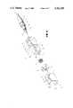
- FIG. 3is an exploded perspective view of a plug according to a first embodiment of the present invention.
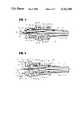
- FIG. 4is a longitudinal section taken along a plane which contains axes A-A' and Y-Y' of FIG. 3 showing the plug in an assembled condition;
- FIG. 5is a section of the first embodiment of the present invention.
- FIG. 6is a perspective view of an adaptor according to a second embodiment of the present invention as well as to the first embodiment
- FIG. 7is an exploded perspective view of a plug according to the second embodiment
- FIG. 8is a longitudinal section taken along a plane which contains axes A-A' and Y-Y' of FIG. 4 showing the plug in an assembled condition;
- FIG. 9is a section of the second embodiment of the present invention.
- FIG. 10is a partly taken away perspective view of a plug according to a third embodiment of the present invention.
- FIG. 11is an exploded perspective view of the plug of FIG. 10 with a second housing removed;
- FIG. 12is a perspective view of an adaptor according to the third embodiment.
- the pluggenerally 14, comprises a first housing 6, a spring 10, a spring retainer 9, and a second housing 7 which are arranged in this order along the center axis A-A' of a cylindrical ferrule 8.
- An axis labelled Y-Y'intersects the axis A-A' perpendicular thereto.
- FIG. 4The plug 14 assembled along the axes A-A' is shown in FIG. 4 in a longitudinal section taken along a plane which contains the axis Y-Y'.
- a fiber optic cable 13is made up of a jacket 13b covering an optical fiber 13a, a tension member 13c surrounding the jacket 13b, and a sheath 13d.
- the optical fiber 13a and the jacket 13bare each shown in a side elevation.
- a cylindrical metallic sleeve 11is coupled over the outer periphery of the tip portion of the sheath 13d and fixed thereto by adhesive.
- a rubber tube 12Disposed around the metallic sleeve 11 and fiber optic cable 13 is a rubber tube 12 in order to absorb tensions acting on the cable 13.
- the sleeve 11is designed to have a larger inside diameter in its tip portion than in its portion which is adhered to the fiber optic cable 13.
- the inner wall of the larger diameter portion of the sleeve 11is threaded to engage a threaded rear end portion of the ferrule 8.
- the ferrule 8accommodates therein the tension member 13c, jacket 13b and optical fiber 13a of the fiber optic cable 13 and connected integrally thereto by adhesive or resin.
- the optical fiber 13ais fixed in place on the center axis A-A' of the ferrule 8.
- the ferrule 8includes a first cylindrical portion 8a extending toward the tip of the ferrule 8 from the threaded rear end portion which engages the sleeve 11 as earlier mentioned, a second cylindrical portion 8b smaller in diameter than the first cylindrical portion 8a, and a threaded portion 8c.
- the ferrule 8is inserted into the first housing 6 such that the first cylindrical portion 8a is positioned in a cylindrical bore 6g of the housing 6.
- the bore 6gis provided with a shoulder 6f which abuts against the front end of the first cylindrical portion 8a of the ferrule 8, thereby restricting the rearward movement of the housing 6.
- Disposed around the second cylindrical portion 8b of the ferrule 8is the spring 10 and around the threaded portion 8c, the spring retainer 9.
- the spring retainer 9is screwed onto the threaded portion 8c.
- the spring 10is seated on the spring retainer 9 at one end and on the shoulder 6f of the housing 6 at the other end.
- the first housing 6 of the plug 14is provided with a pair of flat extensions 6a each being parallel to the axis A-A'.
- Pawls 6dextend toward the axis A-A' of the ferrule 8, i.e., toward each other, from the tips of the respective extensions 6a.
- Each pawl 6dis formed with a tapered portion 6e at its end.
- the housing 6is also provided with recesses 6b in its outer periphery adjacent to the shoulder 6f and recesses 6c adjacent to its rear end.
- Each recess 6bis partly defined by a tapered portion 6b', and each recess 6c by a tapered portion 6c'.
- the first housing 6is received in a rectangular bore 7e formed through the second housing 7.
- Flat extensions 7aextend rearwardly from the second housing 7 along the axis A-A' and each is provided by forming two slits 7c through the housing 7.
- the extensions 7ahave individual pawls 7b at their free ends.
- the pawls 7bwill mate with either one of the recesses 6b and the recesses 6c of the housing 6.
- the sliding movement of the housing 7will be facilitated by the tapered portions 6b' or 6c' of the recesses 6b or 6c as well as by knobs 7d which are provided on the outer periphery of the housing 7.
- the adaptor 15comprises a flange 15b and a pair of hollow blocks 30 which are mounted on opposite sides of the flange 15b.
- Each of the hollow blocks 30is formed with a cylindrical bore 15a and mounted on the flange 15b with the center axes of the bore 15a aligned with that of the other block 30.
- Each block 30includes a pair of parallel side surfaces 15c and 15c' and another pair of parallel side surfaces 15d and 15d'.
- a section perpendicular to the center axis of the blockis substantially rectangular.
- the end face 15g of the block 30is parallel to the general plane of the flange 15b.
- the side surfaces 15d and 15d'respectively are provided with recesses 15e and 15e' which extend parallel to the end face 15g, while terminating respectively at tapered projections 15f and 15f'.
- the projections 15f and 15f'each have a height which is lower than their associated side surface 15d or 15d'.
- the plug 14is shown in a position coupled with the adaptor 15 and abutted against the tip of a ferrule 8' of the opposite plug.
- the second housing 7is moved to the rear portion of the first housing 6.
- the ferrule 8is inserted into the bore 15a of the adaptor 15.
- the plug 14is fusted until the pawls 6d of the first housing 6 mate respectively with the recesses 15e and 15e' of the adjacent hollow block 30 of the adaptor 15.
- the second housing 7is moved toward the tip of the ferrule 8 to bring its pawls 7b into engagement with the recesses 6b.
- the extensions 6a of the first housing 6are entirely nested in the second housing 7, while the ferrule 8 is urged by the spring toward the tip via the spring retainer 9 so as to abut against the opposite ferrule 8'.
- the second housing 7prevents the extensions 6a of the first housing 6 from opening or spreading away from each other. Hence, the plug 14 will not slip off the adaptor 15 unless the second housing 7 is manipulated. This insures a secure connection between the plug 14 and the adaptor 15.
- the embodiment described abovemakes coupling manipulations of and uncoupling an optical fiber connector remarkably easy and, in addition, sets up connection which is secure enough to eliminate separation of the plug from the adaptor as the result of vibrations, impacts, etc.
- a plug 14'according to a second embodiment of the present invention is shown in an exploded view.
- the plug 14'comprises a first housing 16, a spring 10, a square metallic stop 9 having a pair of lugs 9a at two facing sides thereof, a ring-like nut 9', and a second housing 17, which are arranged in this order along the center axis A-A' of a cylindrical ferrule 8.
- An axis labelled Y-Y'is perpendicular to the axis A-A'.
- the plug 14'is shown in FIG. 8 in a longitudinal section taken along a plane which contains the axes A-A' and Y-Y'.
- a fiber optic cord 13is provided integrally with the ferrule 8.
- the ferrule 8 of FIGS. 7 and 8differs from that of FIGS. 3 and 4 in that it includes a generally octagonal stop seat 8d adjacent to the threaded portion thereof.
- the stop seat 8dis adapted to receive the stop 9 as will be described.
- the ferrule 8is accommodated in the first housing 16 with the spring 10 interposed therebetween.
- the spring 10is retained by the nut 9' with the stop 9 intermediate thereto stop 9.
- the nut 9'is fixed to the threaded portion 8c of the ferrule 8.
- the first housing 16is provided in its rear part with a cylindrical bore 16g for accommodating a first cylindrical portion 8a of the ferrule 8 and a shoulder 16f contiguous with the bore 16g.
- the shoulder 16fis adapted to abut against the front end of the first cylindrical portion 8a to restrict the rearward movement of the housing 16.
- a pair of flat extensions 16aextend parallel to the axis A-A' from a position of the housing 16 where the shoulder 16f is located toward the tip of the ferrule 8.
- the extensions 16aare each provided with a pawl 16d at its free end which extends toward the axis A-A' and a rectangular opening 16b at its center.
- the lugs 9a of the stop 9are received in the openings 16b of the respective extensions 16a.
- the width of the openings 16b in a direction parallel to the axis A-A' of the ferrule 8is designed greater than the thickness of the stop 9 so that the first housing 16 may be movable relative to the ferrule 8 to some extent even after the ferrule 8 has been secured in the first housing 16.
- Recesses 16care formed in the respective extensions 16a at the rear of the openings 16b.
- the first housing 16 now carrying the ferrule 8is put in the second housing 17, which is made of plastic.
- the housing 17comprises four walls 170 and 171 which cooperate to define a bore 17d having a rectangular cross-section.
- Each of the upper and lower walls 170is partly configured in a double-wall structure, that is, it partly bifurcates into an inner wall 17a and an outer wall 17c which extend axially at a distance from each other.
- the outer wall 17cincludes a bent portion which is knurled in a direction perpendicular to the axis A-A'.
- the inner wall 17ais free at opposite sides thereof and provided with a pawl 17b at its tip which protrudes toward the axis A-A'.
- the plug 14' described above with reference to FIGS. 7 and 8is shown in a side elevation and in a position coupled with the adaptor 15 shown in FIG. 6.
- the ferrule 8is inserted into the bore 15a of the adaptor 15, while the pawls 16d at the tip of the extensions 16a of the first housing 16 are engaged in the respective recesses 15e and 15e'.
- the second housing 17is moved forwardly until its right and left walls 171 make contact with the respective side surfaces 15c, 15c' of the hollow block 30 and the upper and lower walls 170 with the other respective side surfaces 15d and the respective extensions 16a of the first housing 16.
- the pawls 17b of the inner walls 17a of the second housing 17are received in the respective recesses 16c of the housing 16.
- the front end of the housing 17remains abutted against the flange 15b of the adaptor 15.
- the first housing 17is shifted rearwardly to expose the extensions 16a of the housing 16 to the outside, as shown in FIG. 8. Then, the plug 14' is inserted into the adaptor 15 until the pawls 16d of the extensions 16a mate with the respective recesses 15e and 15'e. Finally, the second housing 17 is moved toward the adaptor 15 with the result that the extensions 16a are individually pressed inwardly by the housing 17 and the pawls 17b of the inner walls 17a of the housing 17 are received in the respective recesses 16c of the housing 16. In this condition, the housing 17 is prevented from being displaced by vibrations of impacts and, thereby causing the plug to disconnect from the adaptor.
- the walls 17a each having the pawl 17b for fixing the second housing 17 to the first housing 16are located inside the housing 17 so that, while the housing 17 is slide on the outer periphery of the housing 16 toward the tip of the plug held by hand.
- the pressure applied to the housing 17 toward the axis A-A'is hardly imparted to the inner walls 17a or the pawls 17b. This allows the housing 17 to smoothly slide and, thereby, enhance efficient manipulation to establish the connection.
- the housing 17since the housing 17 is mated with the adaptor 15 at the front end, the housing 17 will not move even if an external force is applied to the plug in any direction. Therefore, the force acting on the ferrule 18 due to bending as earlier mentioned is almost zero so that the ferrule 18 will not easily be damaged.
- FIG. 10a two-pin type plug according to a third embodiment of the present invention is shown in a partly broken away, sectional perspective view.
- the plugis shown in a perspective view in FIG. 11 with a second housing 10 removed for clarity.
- FIG. 11two optic fiber cables 13 and a tension-resisting member 101 extend from one end of a duplex cable 100.
- Each fiber optic cable 13is identical in construction with the fiber optic cable 13 shown in FIG. 8.
- Two ferrules 8are shown each fixing an optical fiber extending through the fiber optic cable 13 on its center axis.
- a nut 9' and a spring retainer 9are fixed in place on the outer periphery of each ferrule 8 as has been the case with the construction of FIG. 8, while a spring 10 and a ring 80 are coupled over the ferrule 8 but not fixed thereto.
- the ferrules 8are received in a pair of cooperative plug holders 60 and 61 from opposite sides.
- the plug holders 60 and 61fix the ring 80 associated with each ferrule 8 and receive the spring retainer 9 in their aligned notches 60a.
- the notches 60aare dimensioned sufficiently large in the axial direction so that pressing the tip of the ferrule 8 will allow the ferrule 8 to move rearward along the axis thereof overcoming the force of the spring 10.
- Pawls 60b and 61bare provided on the rear side surfaces of the plug holders 60 and 61.
- the plug holders 60 and 61 accommodating the ferrules 8 thereinare in turn accommodated in a housing 62.
- Four projections 62hextend rearwardly from the four walls of the housing 62 and each is provided with an outwardly protruding pawl 62i at its tip.
- the pawls 62iwill each be positioned between the adjacent pawls 60b and 61b of the plug holders 60 and 61 and, thereby, provide a flat surface in cooperation therewith.
- the plug holders 60 and 61, housing 62 accommodating the plug holders 60 and 61 therein, and duplex cable 100are fixed together by second holders 63 and 64.
- the holders 63 and 64are identical in construction and, therefore, only the holder 63 will be described by way of example.
- the holder 63includes a recess 63a for receiving the pawls 60b and 61b of the plug holder 61 and the pawls 62i of the housing 62, recesses 63b for receiving those portions of the projections 62h other than the tips, a cable holding section 63c for holding the cable 100, and a lug 63d for restraining the tension-resisting member 101 of the cable 100.
- the other holder 64is engaged with the holder 63 from above to fix the various members mentioned above in place.
- Screws 65(in FIG. 10) are each passed through a hole 63f, while a nut 66 is driven over each screw 65 to thereby fasten the holders 63 and 64 to each other.
- Characteristic features of the third embodimentreside in the configurations of the housing 62 and a housing 70 which is used in the manner shown in FIG. 10.
- the housing 62is coupled with an adaptor 150 shown in FIG. 12.
- the upper and lower walls of the housing 62are each provided with a flat projection 62a extending forwarding in a direction parallel to the axis of the ferrule 8, and a opening 62e.
- the projection 62ais formed with a tapered portion 62d at its base end and terminates at a pawl 62b at its free end, the pawl 62b protruding in both directions, i.e., toward and away from the axis A-A' of the ferrule 8.
- Provided on the inner sides of the pawls 62bare tapered portions 62c adapted to facilitate coupling of the housing 62 with the adaptor 150.
- the front end of the housing 62is provided with a flange 62f, while a rear end portion of the same is formed with notches 62g.
- the notches 62gwill not be concealed by the holder 63 or 64 when the housing 62 is fixed in place by the holders 63 and 64.
- the housing 62is accommodated in the second housing 70.
- the inner surfaces of the second housing 70make contact with the outer surfaces of the housing 62.
- Upper and lower walls 700 of the second housing 70are each bifurcated by a slot 70d away from the ferrule tips to provide an outer wall 70c and an inner wall 70a lying one above the other.
- Each inner wall 70ais free at opposite sides thereof and formed with a pawl 70b at the tip which extends toward the ferrule axis.
- the pawl 70bis engated in the notch 62g on the outer periphery of the housing 62 to fix the second housing 70 in place.
- the front end of the housing 70abuts against the flange 62f and the pawl 70b against the tapered portion at the base of the extension 62a, whereby the housing 70 is securely retained.
- the adaptor 150 with which the housing 62 will be coupledincludes a flange 150b and a pair of hollow blocks 300 provided on opposite sides of the flange 150b.
- Each hollow block 300has side surfaces 150d and 150d' which are parallel to each other and side surfaces 150c and 150c' which are not parallel to each other.
- the hollow block 300has a substantially trapezoidal section when taken in a direction perpendicular to the axis of the block 300.
- the end 150g of the block 300extends parallel to the general plane of the flange 150b.
- Recesses 150erespectively are formed in the side surfaces 150d and 150d' in parallel to the end 150g.
- the four side surfaces 150c, 150c', 150d and 150d'are provided with tapered protuberances 150f and 150f' at their free ends.
- the height of the protuberances 150f and 150f' from the recesses 150e, 150e'is smaller than that of the side surfaces 150d and 150d'.
- the ferrules 8are thrusted each into a bore 150a of the adaptor 150 and, then, the flange 62f at the end of the housing 62 is brought into abutting engagement with the flange 150b of the adaptor 150. This causes the pawls 62b of the housing 62 to be retained by the respective recesses 150e of the adaptor 150. This is followed by sliding the second housing 70 toward the tip of the ferrule 8 until it abuts against the flange 62f.
- the pawls 62bare retained between the second housing 70 and the recesses 150e of the adaptor 150 so that, even if the plug and adaptor are pulled away from each other, the pawls 62b will not slip out of the recesses 150e. Such allows the plug and the adaptor to couple very securely with each other.
Landscapes
- Physics & Mathematics (AREA)
- General Physics & Mathematics (AREA)
- Optics & Photonics (AREA)
- Mechanical Coupling Of Light Guides (AREA)
Abstract
Description
Claims (7)
Applications Claiming Priority (4)
| Application Number | Priority Date | Filing Date | Title |
|---|---|---|---|
| JP59-63956 | 1984-03-30 | ||
| JP59062427AJPS60205511A (en) | 1984-03-30 | 1984-03-30 | Optical fiber connector |
| JP59063956AJPS60205512A (en) | 1984-03-30 | 1984-03-30 | Optical fiber connector |
| JP59-62427 | 1984-03-30 |
Publications (1)
| Publication Number | Publication Date |
|---|---|
| US4762389Atrue US4762389A (en) | 1988-08-09 |
Family
ID=26403471
Family Applications (1)
| Application Number | Title | Priority Date | Filing Date |
|---|---|---|---|
| US06/716,064Expired - LifetimeUS4762389A (en) | 1984-03-30 | 1985-03-26 | Optical fiber connector |
Country Status (4)
| Country | Link |
|---|---|
| US (1) | US4762389A (en) |
| EP (1) | EP0156397B1 (en) |
| CA (1) | CA1255522A (en) |
| DE (1) | DE3572870D1 (en) |
Cited By (59)
| Publication number | Priority date | Publication date | Assignee | Title |
|---|---|---|---|---|
| US4846544A (en)* | 1987-10-14 | 1989-07-11 | Societa' Cavi Pirelli S.P.A. | Method of interconnecting optical fiber cables and connector therefore |
| US4968113A (en)* | 1989-04-05 | 1990-11-06 | Amp Incorporated | Optical fiber nut |
| US5029970A (en)* | 1989-01-31 | 1991-07-09 | Messerschmitt-Bolkow-Blohm Gmbh | Adapter for a light guide for medical laser apparatus including safety device |
| US5042891A (en)* | 1990-06-21 | 1991-08-27 | Amp Incorporated | Active device mount assembly with interface mount for push-pull coupling type optical fiber connectors |
| US5082344A (en)* | 1990-03-09 | 1992-01-21 | Mulholland Denis G | Adapter assembly with improved receptacle for a push-pull coupling type of optical fiber connector |
| US5091990A (en)* | 1991-02-15 | 1992-02-25 | Augat Communications Group | Fiber-optic connector |
| US5101463A (en)* | 1991-05-03 | 1992-03-31 | Minnesota Mining And Manufacturing Company | Push-pull optical fiber connector |
| US5123071A (en)* | 1990-03-09 | 1992-06-16 | Amp Incorporated | Overconnector assembly for a pair of push-pull coupling type optical fiber connectors |
| US5134677A (en)* | 1991-02-15 | 1992-07-28 | Augat Communications Group | Fiber-optic connector and method of assembly |
| US5142597A (en)* | 1990-07-27 | 1992-08-25 | Amp Incorporated | Interconnect assembly for wall outlet |
| US5159652A (en)* | 1990-06-21 | 1992-10-27 | Radiall | Quick-action connector for optical fibers |
| US5166995A (en)* | 1984-06-08 | 1992-11-24 | Amp Incorporated | Polarized connector |
| US5228104A (en)* | 1990-05-18 | 1993-07-13 | Thomson Broadcast | Optical connection system and its use in the transmission of video signals |
| US5287425A (en)* | 1993-02-26 | 1994-02-15 | Foxconn International, Inc. | Optical fiber SC type connector assembly with partly pre-assembled components |
| US5394497A (en)* | 1994-02-22 | 1995-02-28 | The Whitaker Corporation | Captivated fiber optic connector |
| US5809192A (en)* | 1994-06-22 | 1998-09-15 | The Whitaker Corporation | Optical fiber connector having enhanced assembly means |
| US5815618A (en)* | 1996-06-07 | 1998-09-29 | Molex Incorporated | Adaptor for interconnecting optical fibers |
| AU698116B3 (en)* | 1997-12-22 | 1998-10-22 | Krone Gmbh | Optical fibre connector |
| US5887100A (en)* | 1996-05-14 | 1999-03-23 | Kingfisher International Pty. Ltd. | Optical fibre connector device |
| EP1037076A1 (en)* | 1999-03-17 | 2000-09-20 | Reichle & De-Massari AG | Lightguide contact connector for connector assemblies |
| US6126325A (en)* | 1998-01-21 | 2000-10-03 | Fujitsu Limited | Receptacle module for optical telecommunication |
| AU726349B2 (en)* | 1996-05-14 | 2000-11-02 | Kingfisher International Pty. Ltd. | An optical fibre device |
| DE19955316A1 (en)* | 1999-11-17 | 2001-05-23 | Delphi Tech Inc | Connectors |
| US6302591B1 (en)* | 1998-06-29 | 2001-10-16 | Yazaki Corporation | Optical fiber connector |
| US6352373B1 (en)* | 1999-08-05 | 2002-03-05 | Yazaki Corporation | Optical connector |
| US6428215B1 (en) | 2000-12-27 | 2002-08-06 | Adc Telecommunications, Inc. | Tunable fiber optic connector and method for assembling |
| US6511230B1 (en) | 2000-02-04 | 2003-01-28 | Panduit Corp. | Fiber optic connection system |
| US6572275B2 (en)* | 2000-11-28 | 2003-06-03 | The Furukawa Electric Co., Ltd. | Optical connector |
| US20030108303A1 (en)* | 2001-11-26 | 2003-06-12 | Autonetworks Technologies, Ltd. | Optical connector and structure of holding an optical fiber cord |
| US6591056B1 (en) | 2000-03-30 | 2003-07-08 | Delphi Technologies, Inc. | Connector terminus springs |
| US6592267B1 (en)* | 2002-01-14 | 2003-07-15 | Yu-Feng Cheng | Optical fiber plug |
| US6629782B2 (en) | 2002-02-04 | 2003-10-07 | Adc Telecommunications, Inc. | Tuned fiber optic connector and method |
| US20030231836A1 (en)* | 2002-03-18 | 2003-12-18 | Robertson Bruce Elphinston | Optical fibre connector system |
| US6712521B1 (en)* | 2002-12-20 | 2004-03-30 | Japan Aviation Electronics Industry, Limited | Optical connector enabling multicore structure by efficiently utilizing space |
| US20040076384A1 (en)* | 2002-08-02 | 2004-04-22 | Kiyoshi Kato | Optical module |
| US20040157499A1 (en)* | 2003-02-07 | 2004-08-12 | Hypertronics Corporation | Connecting device |
| US6883976B2 (en)* | 2001-07-30 | 2005-04-26 | Seikoh Giken Co., Ltd. | Optical fiber ferrule assembly and optical module and optical connector using the same |
| US20060089039A1 (en)* | 2004-10-22 | 2006-04-27 | Caveney Jack E | Push-pull plugs and tools |
| US20060098923A1 (en)* | 2003-04-30 | 2006-05-11 | Fujikura Ltd. | Optical connector assembly, connector holder, and optical connector |
| US20060210225A1 (en)* | 2003-04-30 | 2006-09-21 | Kunihiko Fujiwara | Optical transceiver and optical connector |
| US20070098331A1 (en)* | 2004-11-29 | 2007-05-03 | Mudd Ronald L | Optical fiber connector and method of assembly |
| USD596127S1 (en) | 2003-11-21 | 2009-07-14 | Hypertronics Corporation | Electrical connector |
| US20130209053A1 (en)* | 2010-10-27 | 2013-08-15 | Alcatel Lucent | Assembly comprising at least one optical fibre and a mounting device |
| US20140308011A1 (en)* | 2012-02-27 | 2014-10-16 | Sunsea Telecommunications Co.,Ltd. | High-density Fiber Connector and Assembling Method Thereof |
| US9081154B2 (en) | 2012-09-12 | 2015-07-14 | Tyco Electronics Raychem Bvba | Method of tuning a fiber optic connector |
| US20160334593A1 (en)* | 2005-06-30 | 2016-11-17 | Weatherford Technology Holdings, Llc | Optical waveguide feedthrough assembly |
| USD787448S1 (en) | 2014-08-18 | 2017-05-23 | Interlemo Holding S.A. | Electrical connector |
| US20180106972A1 (en)* | 2014-02-14 | 2018-04-19 | Adc Telecommunications (Shanghai) Distribution Co., Ltd. | Fiber optic connector and method of assembling the same |
| US20190278027A1 (en)* | 2016-09-23 | 2019-09-12 | Hexatronic Group Ab | Method of assembling a fibre connector |
| USD863221S1 (en) | 2015-09-04 | 2019-10-15 | Interlemo Holding Sa | Illuminable female connector |
| US10895698B2 (en) | 2015-11-30 | 2021-01-19 | Commscope Technologies Llc | Fiber optic connector and assembly thereof |
| US10976500B2 (en) | 2015-12-16 | 2021-04-13 | Commscope Technologies Llc | Field installed fiber optic connector |
| US11002917B2 (en) | 2014-02-14 | 2021-05-11 | Commscope Telecommunications (Shanghai) Co. Ltd. | Fiber optic connector and method of assembling the same |
| US11016250B2 (en)* | 2017-12-19 | 2021-05-25 | Us Conec, Ltd. | Mini duplex connector with push-pull polarity mechanism, carrier, and rail-receiving crimp body |
| US11119283B2 (en) | 2014-07-09 | 2021-09-14 | Commscope Telecommunications (Shanghai) Co. Ltd. | Optical fiber connector and method of assembling the same on site |
| US11372172B2 (en) | 2012-11-30 | 2022-06-28 | Commscope Technologies Llc | Fiber optic connector with field installable outer connector housing |
| US20230091327A1 (en)* | 2020-04-23 | 2023-03-23 | Us Conec Ltd. | Miniature Multi-fiber Ferrule |
| US20230333328A1 (en)* | 2022-04-18 | 2023-10-19 | Ortronics, Inc. | System for Fiber Connector Assembly |
| US12321017B2 (en) | 2020-04-23 | 2025-06-03 | Us Conec Ltd. | Fiber optic ferrule and fiber optic ferrule receiver |
Families Citing this family (9)
| Publication number | Priority date | Publication date | Assignee | Title |
|---|---|---|---|---|
| US4779949A (en)* | 1985-04-05 | 1988-10-25 | Dainichi-Nippon Cables, Ltd. | Connector having axially slit end for gripping optical fiber |
| US5233674A (en)* | 1991-11-21 | 1993-08-03 | Methode Electronics, Inc. | Fiber optic connector with sliding tab release |
| DE4330941C1 (en)* | 1993-09-08 | 1995-03-02 | Siemens Ag | Connectors |
| JP3798455B2 (en)* | 1994-11-04 | 2006-07-19 | ザ ウィタカー コーポレーション | Fiber optic connector |
| US6048104A (en)* | 1996-09-06 | 2000-04-11 | Seiko Seiki Kabushiki Kaisha | Ferrule for use in optical fiber connector |
| DE19539549C1 (en)* | 1995-10-12 | 1996-12-05 | Siemens Ag | Optical connector arrangement for electronic devices |
| US6116788A (en)* | 1996-10-11 | 2000-09-12 | Siemens Aktiengesellschaft | Optical plug connector |
| US9696500B2 (en)* | 2012-08-31 | 2017-07-04 | Corning Optical Communications LLC | Female hardened optical connectors for use with hybrid receptacle |
| EP3588154A1 (en) | 2018-06-28 | 2020-01-01 | Diamond SA | Plug-in element for an optical plug connector |
Citations (7)
| Publication number | Priority date | Publication date | Assignee | Title |
|---|---|---|---|---|
| US4240695A (en)* | 1979-06-20 | 1980-12-23 | E. I. Du Pont De Nemours And Company | Optical fibers connector |
| US4268115A (en)* | 1979-06-01 | 1981-05-19 | Tetra-Tech, Inc. | Quick-release fiber-optic connector |
| US4418983A (en)* | 1981-03-16 | 1983-12-06 | Amp Incorporated | Optical waveguide connector |
| US4435036A (en)* | 1980-05-30 | 1984-03-06 | Anritsu Electric Company Limited | Optical fiber connector with mutually engaging, oppositely tapered surfaces |
| US4477146A (en)* | 1981-03-16 | 1984-10-16 | Amp Incorporated | Optical waveguide connector |
| US4539476A (en)* | 1980-11-28 | 1985-09-03 | Tokyo Shibaura Denki Kabushiki Kaisha | Module for a fiber optic link |
| US4684210A (en)* | 1983-05-31 | 1987-08-04 | Alps Electric Co., Ltd. | Light transmission device |
Family Cites Families (6)
| Publication number | Priority date | Publication date | Assignee | Title |
|---|---|---|---|---|
| GB1411877A (en)* | 1973-02-27 | 1975-10-29 | Cavis Cavetti Isolati Spa | Fastener for light-guide cables |
| US3904269A (en)* | 1974-01-28 | 1975-09-09 | Us Navy | Fiber optic cable connector |
| US4186997A (en)* | 1977-02-14 | 1980-02-05 | Amp Incorporated | Overlap type waveguide connector assembly and method |
| GB2086602B (en)* | 1980-11-04 | 1985-11-27 | Cannon Electric Great Britain | Fibre optic connector |
| CA1196221A (en)* | 1981-03-16 | 1985-11-05 | Terry P. Bowen | Optical waveguide connector |
| FR2559919B1 (en)* | 1984-02-17 | 1986-05-16 | Socapex | CENTERING TIP FOR OPTICAL FIBER AND PLUG COMPRISING SUCH A TIP |
- 1985
- 1985-03-26USUS06/716,064patent/US4762389A/ennot_activeExpired - Lifetime
- 1985-03-29DEDE8585103847Tpatent/DE3572870D1/ennot_activeExpired
- 1985-03-29EPEP85103847Apatent/EP0156397B1/ennot_activeExpired
- 1985-03-29CACA000477880Apatent/CA1255522A/ennot_activeExpired
Patent Citations (7)
| Publication number | Priority date | Publication date | Assignee | Title |
|---|---|---|---|---|
| US4268115A (en)* | 1979-06-01 | 1981-05-19 | Tetra-Tech, Inc. | Quick-release fiber-optic connector |
| US4240695A (en)* | 1979-06-20 | 1980-12-23 | E. I. Du Pont De Nemours And Company | Optical fibers connector |
| US4435036A (en)* | 1980-05-30 | 1984-03-06 | Anritsu Electric Company Limited | Optical fiber connector with mutually engaging, oppositely tapered surfaces |
| US4539476A (en)* | 1980-11-28 | 1985-09-03 | Tokyo Shibaura Denki Kabushiki Kaisha | Module for a fiber optic link |
| US4418983A (en)* | 1981-03-16 | 1983-12-06 | Amp Incorporated | Optical waveguide connector |
| US4477146A (en)* | 1981-03-16 | 1984-10-16 | Amp Incorporated | Optical waveguide connector |
| US4684210A (en)* | 1983-05-31 | 1987-08-04 | Alps Electric Co., Ltd. | Light transmission device |
Cited By (115)
| Publication number | Priority date | Publication date | Assignee | Title |
|---|---|---|---|---|
| US5166995A (en)* | 1984-06-08 | 1992-11-24 | Amp Incorporated | Polarized connector |
| AU612696B2 (en)* | 1987-10-14 | 1991-07-18 | Societa' Cavi Pirelli S.P.A. | Connector for optical fibers and method for the axial positioning of an optical fiber in the connector |
| US4846544A (en)* | 1987-10-14 | 1989-07-11 | Societa' Cavi Pirelli S.P.A. | Method of interconnecting optical fiber cables and connector therefore |
| US5029970A (en)* | 1989-01-31 | 1991-07-09 | Messerschmitt-Bolkow-Blohm Gmbh | Adapter for a light guide for medical laser apparatus including safety device |
| US4968113A (en)* | 1989-04-05 | 1990-11-06 | Amp Incorporated | Optical fiber nut |
| US5082344A (en)* | 1990-03-09 | 1992-01-21 | Mulholland Denis G | Adapter assembly with improved receptacle for a push-pull coupling type of optical fiber connector |
| US5123071A (en)* | 1990-03-09 | 1992-06-16 | Amp Incorporated | Overconnector assembly for a pair of push-pull coupling type optical fiber connectors |
| US5228104A (en)* | 1990-05-18 | 1993-07-13 | Thomson Broadcast | Optical connection system and its use in the transmission of video signals |
| US5042891A (en)* | 1990-06-21 | 1991-08-27 | Amp Incorporated | Active device mount assembly with interface mount for push-pull coupling type optical fiber connectors |
| US5159652A (en)* | 1990-06-21 | 1992-10-27 | Radiall | Quick-action connector for optical fibers |
| US5142597A (en)* | 1990-07-27 | 1992-08-25 | Amp Incorporated | Interconnect assembly for wall outlet |
| US5134677A (en)* | 1991-02-15 | 1992-07-28 | Augat Communications Group | Fiber-optic connector and method of assembly |
| US5091990A (en)* | 1991-02-15 | 1992-02-25 | Augat Communications Group | Fiber-optic connector |
| US5101463A (en)* | 1991-05-03 | 1992-03-31 | Minnesota Mining And Manufacturing Company | Push-pull optical fiber connector |
| US5287425A (en)* | 1993-02-26 | 1994-02-15 | Foxconn International, Inc. | Optical fiber SC type connector assembly with partly pre-assembled components |
| US5394497A (en)* | 1994-02-22 | 1995-02-28 | The Whitaker Corporation | Captivated fiber optic connector |
| US5809192A (en)* | 1994-06-22 | 1998-09-15 | The Whitaker Corporation | Optical fiber connector having enhanced assembly means |
| AU726349B2 (en)* | 1996-05-14 | 2000-11-02 | Kingfisher International Pty. Ltd. | An optical fibre device |
| US5887100A (en)* | 1996-05-14 | 1999-03-23 | Kingfisher International Pty. Ltd. | Optical fibre connector device |
| US5815618A (en)* | 1996-06-07 | 1998-09-29 | Molex Incorporated | Adaptor for interconnecting optical fibers |
| AU698116B3 (en)* | 1997-12-22 | 1998-10-22 | Krone Gmbh | Optical fibre connector |
| US6126325A (en)* | 1998-01-21 | 2000-10-03 | Fujitsu Limited | Receptacle module for optical telecommunication |
| US6302591B1 (en)* | 1998-06-29 | 2001-10-16 | Yazaki Corporation | Optical fiber connector |
| EP1037076A1 (en)* | 1999-03-17 | 2000-09-20 | Reichle & De-Massari AG | Lightguide contact connector for connector assemblies |
| US6352373B1 (en)* | 1999-08-05 | 2002-03-05 | Yazaki Corporation | Optical connector |
| DE19955316A1 (en)* | 1999-11-17 | 2001-05-23 | Delphi Tech Inc | Connectors |
| US6454463B1 (en) | 1999-11-17 | 2002-09-24 | Delphi Technologies, Inc. | Plug connector |
| US6511230B1 (en) | 2000-02-04 | 2003-01-28 | Panduit Corp. | Fiber optic connection system |
| US6591056B1 (en) | 2000-03-30 | 2003-07-08 | Delphi Technologies, Inc. | Connector terminus springs |
| US6572275B2 (en)* | 2000-11-28 | 2003-06-03 | The Furukawa Electric Co., Ltd. | Optical connector |
| US6695489B2 (en) | 2000-12-27 | 2004-02-24 | Adc Telecommunications, Inc. | Tunable fiber optic connector and method for assembling |
| US6428215B1 (en) | 2000-12-27 | 2002-08-06 | Adc Telecommunications, Inc. | Tunable fiber optic connector and method for assembling |
| US20050147359A1 (en)* | 2001-07-30 | 2005-07-07 | Seikoh Giken Co., Ltd | Optical fiber ferrule assembly and optical module and optical connector using the same |
| US6883976B2 (en)* | 2001-07-30 | 2005-04-26 | Seikoh Giken Co., Ltd. | Optical fiber ferrule assembly and optical module and optical connector using the same |
| DE10255100B4 (en)* | 2001-11-26 | 2013-05-23 | Autonetworks Technologies, Ltd. | An optical connector and arrangement for holding an optical fiber line |
| US6893164B2 (en)* | 2001-11-26 | 2005-05-17 | Autonetworks Technologies, Ltd. | Optical connector and structure of holding an optical fiber cord |
| US20030108303A1 (en)* | 2001-11-26 | 2003-06-12 | Autonetworks Technologies, Ltd. | Optical connector and structure of holding an optical fiber cord |
| US6592267B1 (en)* | 2002-01-14 | 2003-07-15 | Yu-Feng Cheng | Optical fiber plug |
| US6629782B2 (en) | 2002-02-04 | 2003-10-07 | Adc Telecommunications, Inc. | Tuned fiber optic connector and method |
| US7163342B2 (en) | 2002-03-18 | 2007-01-16 | Kingfisher International, Pty Ltd | Optical fibre connector system |
| US7473037B2 (en) | 2002-03-18 | 2009-01-06 | Kingfisher International, Pty Ltd | Optical fibre connector system |
| US20030231836A1 (en)* | 2002-03-18 | 2003-12-18 | Robertson Bruce Elphinston | Optical fibre connector system |
| US20040076384A1 (en)* | 2002-08-02 | 2004-04-22 | Kiyoshi Kato | Optical module |
| US7090412B2 (en)* | 2002-08-02 | 2006-08-15 | Sumitomo Electric Industries, Ltd. | Optical module |
| US6712521B1 (en)* | 2002-12-20 | 2004-03-30 | Japan Aviation Electronics Industry, Limited | Optical connector enabling multicore structure by efficiently utilizing space |
| US20100144183A1 (en)* | 2003-02-07 | 2010-06-10 | Hypertronics Corporation | Method of mounting a connector assembly |
| US7938670B2 (en) | 2003-02-07 | 2011-05-10 | Hypertronics Corporation | Method of mounting a connector assembly |
| US7326091B2 (en) | 2003-02-07 | 2008-02-05 | Hypertronics Corporation | Connecting device |
| US7661995B2 (en) | 2003-02-07 | 2010-02-16 | Hypertronics Corporation | Connecting device |
| US20080166906A1 (en)* | 2003-02-07 | 2008-07-10 | Hypertronics Corporation | Connecting device |
| US20040157499A1 (en)* | 2003-02-07 | 2004-08-12 | Hypertronics Corporation | Connecting device |
| US20060210225A1 (en)* | 2003-04-30 | 2006-09-21 | Kunihiko Fujiwara | Optical transceiver and optical connector |
| US7918610B2 (en) | 2003-04-30 | 2011-04-05 | Fujikura Ltd. | Optical transceiver and optical connector |
| US7287914B2 (en) | 2003-04-30 | 2007-10-30 | Fujikura Ltd. | Optical connector assembly, connector holder, and optical connector |
| US20060098923A1 (en)* | 2003-04-30 | 2006-05-11 | Fujikura Ltd. | Optical connector assembly, connector holder, and optical connector |
| US20090196556A1 (en)* | 2003-04-30 | 2009-08-06 | Nec Corporation | Optical transceiver and optical connector |
| US7534052B2 (en) | 2003-04-30 | 2009-05-19 | Fujikura Ltd. | Optical transceiver and optical connector |
| USD596127S1 (en) | 2003-11-21 | 2009-07-14 | Hypertronics Corporation | Electrical connector |
| USD615932S1 (en) | 2003-11-21 | 2010-05-18 | Hypertronics Corporation | Electrical connector |
| USD616825S1 (en) | 2003-11-21 | 2010-06-01 | Hypertronics Corporation | Electrical connector |
| US20080057770A1 (en)* | 2004-10-22 | 2008-03-06 | Panduit Corp. | Push-Pull Plugs and Tools |
| US7297013B2 (en) | 2004-10-22 | 2007-11-20 | Panduit Corp. | Push-pull plugs and tools |
| US20060089039A1 (en)* | 2004-10-22 | 2006-04-27 | Caveney Jack E | Push-pull plugs and tools |
| US7534128B2 (en) | 2004-10-22 | 2009-05-19 | Panduit Corp. | Push-pull plugs and tools |
| US7281859B2 (en)* | 2004-11-29 | 2007-10-16 | Corning Cable Systems Llc | Optical fiber connector and method of assembly |
| US20070098331A1 (en)* | 2004-11-29 | 2007-05-03 | Mudd Ronald L | Optical fiber connector and method of assembly |
| US20160334593A1 (en)* | 2005-06-30 | 2016-11-17 | Weatherford Technology Holdings, Llc | Optical waveguide feedthrough assembly |
| US10606000B2 (en)* | 2005-06-30 | 2020-03-31 | Weatherford Technology Holdings, Llc | Optical waveguide feedthrough assembly |
| US20130209053A1 (en)* | 2010-10-27 | 2013-08-15 | Alcatel Lucent | Assembly comprising at least one optical fibre and a mounting device |
| US9563024B2 (en)* | 2012-02-27 | 2017-02-07 | Sunsea Telecommunications Co., Ltd. | High-density fiber connector with front casing defining engagement recess and rear casing including hook engaging with each other |
| US20140308011A1 (en)* | 2012-02-27 | 2014-10-16 | Sunsea Telecommunications Co.,Ltd. | High-density Fiber Connector and Assembling Method Thereof |
| US10663675B2 (en) | 2012-09-12 | 2020-05-26 | Commscope Technologies Llc | Tuned fiber optic connectors |
| US9081154B2 (en) | 2012-09-12 | 2015-07-14 | Tyco Electronics Raychem Bvba | Method of tuning a fiber optic connector |
| US10168489B2 (en) | 2012-09-12 | 2019-01-01 | Commscope Technologies Llc | Tuned fiber optic connectors |
| US11880074B2 (en) | 2012-11-30 | 2024-01-23 | Commscope Technologies Llc | Fiber optic connector with field installable outer connector housing |
| US11372172B2 (en) | 2012-11-30 | 2022-06-28 | Commscope Technologies Llc | Fiber optic connector with field installable outer connector housing |
| US20180106972A1 (en)* | 2014-02-14 | 2018-04-19 | Adc Telecommunications (Shanghai) Distribution Co., Ltd. | Fiber optic connector and method of assembling the same |
| US12072537B2 (en) | 2014-02-14 | 2024-08-27 | Commscope Telecommunications (Shanghai) Co. Ltd. | Fiber optic connector and method of assembling the same |
| US10698166B2 (en)* | 2014-02-14 | 2020-06-30 | Commscope Telecommunications (Shanghai) Co. Ltd. | Fiber optic connector and method of assembling the same |
| US11506844B2 (en) | 2014-02-14 | 2022-11-22 | Commscope Telecommunications (Shanghai) Co. Ltd. | Fiber optic connector and method of assembling the same |
| US11474306B2 (en) | 2014-02-14 | 2022-10-18 | Commscope Telecommunications (Shanghai) Co. Ltd. | Fiber optic connector and method of assembling the same |
| US12228773B1 (en) | 2014-02-14 | 2025-02-18 | Commscope Telecommunications (Shanghai) Co., Ltd. | Fiber optic connector and method of assembling the same |
| US11002917B2 (en) | 2014-02-14 | 2021-05-11 | Commscope Telecommunications (Shanghai) Co. Ltd. | Fiber optic connector and method of assembling the same |
| USD810029S1 (en) | 2014-02-18 | 2018-02-13 | Interlemo Holding Sa | Electrical connector |
| US11119283B2 (en) | 2014-07-09 | 2021-09-14 | Commscope Telecommunications (Shanghai) Co. Ltd. | Optical fiber connector and method of assembling the same on site |
| US12287518B2 (en) | 2014-07-09 | 2025-04-29 | Commscope Telecommunications (Shanghai) Co. Ltd. | Optical fiber connector and method of assembling the same on site |
| US11726270B2 (en) | 2014-07-09 | 2023-08-15 | CommScope Telecommunications (Shanghai) Co. Ltd | Optical fiber connector and method of assembling the same on site |
| USD787448S1 (en) | 2014-08-18 | 2017-05-23 | Interlemo Holding S.A. | Electrical connector |
| USD863221S1 (en) | 2015-09-04 | 2019-10-15 | Interlemo Holding Sa | Illuminable female connector |
| US11409051B2 (en) | 2015-11-30 | 2022-08-09 | Commscope Technologies Llc | Fiber optic connector and assembly thereof |
| US10895698B2 (en) | 2015-11-30 | 2021-01-19 | Commscope Technologies Llc | Fiber optic connector and assembly thereof |
| US12072539B2 (en) | 2015-11-30 | 2024-08-27 | Commscope Technologies Llc | Fiber optic connector and assembly thereof |
| US10976500B2 (en) | 2015-12-16 | 2021-04-13 | Commscope Technologies Llc | Field installed fiber optic connector |
| US11378756B2 (en) | 2015-12-16 | 2022-07-05 | Commscope Technologies Llc | Field installed fiber optic connector |
| US11789216B2 (en) | 2015-12-16 | 2023-10-17 | Commscope Technologies Llc | Field installed fiber optic connector |
| US10890721B2 (en)* | 2016-09-23 | 2021-01-12 | Hexatronic Group Ab | Method of assembling a fibre connector |
| US20190278027A1 (en)* | 2016-09-23 | 2019-09-12 | Hexatronic Group Ab | Method of assembling a fibre connector |
| US11808994B1 (en)* | 2017-12-19 | 2023-11-07 | Us Conec Ltd. | Mini duplex connector with push-pull polarity mechanism and carrier |
| US12248187B2 (en) | 2017-12-19 | 2025-03-11 | Us Conec Ltd. | Crimp body for mini duplex connector with push-pull polarity mechanism and carrier |
| US11016250B2 (en)* | 2017-12-19 | 2021-05-25 | Us Conec, Ltd. | Mini duplex connector with push-pull polarity mechanism, carrier, and rail-receiving crimp body |
| US20230358974A1 (en)* | 2017-12-19 | 2023-11-09 | Us Conec Ltd. | Mini duplex connector with push-pull polarity mechanism and carrier |
| US20230080980A1 (en)* | 2017-12-19 | 2023-03-16 | Us Conec Ltd | Mini duplex connector with push-pull polarity mechanism and carrier |
| US12124093B2 (en)* | 2017-12-19 | 2024-10-22 | Us Conec Ltd. | Adapter for small form factor duplex fiber optic connectors |
| US20240168243A1 (en)* | 2017-12-19 | 2024-05-23 | Us Conec Ltd. | Mini duplex connector with push-pull polarity mechanism and carrier |
| US11733466B2 (en)* | 2017-12-19 | 2023-08-22 | Us Conec Ltd. | Mini duplex connector with push-pull polarity mechanism and carrier |
| US20240264383A1 (en)* | 2020-04-23 | 2024-08-08 | Us Conec Ltd. | Miniature Multi-fiber Ferrule |
| US12019278B2 (en)* | 2020-04-23 | 2024-06-25 | Us Conec Ltd. | Miniature multi-fiber ferrule |
| US20230161115A1 (en)* | 2020-04-23 | 2023-05-25 | Us Conec Ltd. | Fiber optic ferrule and fiber optic ferrule receiver |
| US11914195B2 (en)* | 2020-04-23 | 2024-02-27 | Us Conec Ltd. | Fiber optic ferrule and fiber optic ferrule receiver |
| US20230091327A1 (en)* | 2020-04-23 | 2023-03-23 | Us Conec Ltd. | Miniature Multi-fiber Ferrule |
| US12321017B2 (en) | 2020-04-23 | 2025-06-03 | Us Conec Ltd. | Fiber optic ferrule and fiber optic ferrule receiver |
| US12379549B2 (en)* | 2020-04-23 | 2025-08-05 | Us Conec Ltd. | Miniature multi-fiber ferrule |
| WO2023205045A1 (en)* | 2022-04-18 | 2023-10-26 | Ortronics, Inc. | System for fiber connector assembly |
| US20230333328A1 (en)* | 2022-04-18 | 2023-10-19 | Ortronics, Inc. | System for Fiber Connector Assembly |
| US12416768B2 (en)* | 2022-04-18 | 2025-09-16 | Legrand DPC, LLC | System for fiber connector assembly |
Also Published As
| Publication number | Publication date |
|---|---|
| CA1255522A (en) | 1989-06-13 |
| EP0156397A2 (en) | 1985-10-02 |
| EP0156397B1 (en) | 1989-09-06 |
| DE3572870D1 (en) | 1989-10-12 |
| EP0156397A3 (en) | 1986-02-12 |
Similar Documents
| Publication | Publication Date | Title |
|---|---|---|
| US4762389A (en) | Optical fiber connector | |
| US5123071A (en) | Overconnector assembly for a pair of push-pull coupling type optical fiber connectors | |
| US10429594B2 (en) | Multiport assemblies including retention features | |
| EP3682277B1 (en) | Fiber optic connector with boot-integrated release | |
| US7234877B2 (en) | Fiber optic industrial connector | |
| US5082344A (en) | Adapter assembly with improved receptacle for a push-pull coupling type of optical fiber connector | |
| US6024498A (en) | Optical fiber connector assembly | |
| EP0685750B1 (en) | Connector for connecting an optical fiber cable | |
| US5159652A (en) | Quick-action connector for optical fibers | |
| EP1073923B1 (en) | Plug housing with attached cantilever latch for a fiber optic connector | |
| EP3405824B1 (en) | Fiber optic connector with small profile, and cable assemblies and systems including the same | |
| EP0935148B1 (en) | Optical fiber connector with cable anchoring means | |
| MXPA06010746A (en) | Field installable optical fiber connector. | |
| US20220269015A1 (en) | Fiber optic connector | |
| EP0053914A1 (en) | Fibre optic connectors and lens elements therefor | |
| JP2019158957A (en) | Lc type simple connector plug and optical connector device using plug | |
| US11650376B2 (en) | Optical fiber connectors | |
| US5926597A (en) | Connector for optical fiber | |
| JP3221800B2 (en) | Optical connector | |
| US6893161B2 (en) | Optical connector device | |
| EP4091007B1 (en) | Preconnectorized multi-fiber drop cables | |
| WO2024142504A1 (en) | Auxiliary tool and connector with auxiliary tool attached thereto |
Legal Events
| Date | Code | Title | Description |
|---|---|---|---|
| AS | Assignment | Owner name:NEC CORPORATION, 33-1, SHIBA 5-CHOME, MINATO-KU, T Free format text:ASSIGNMENT OF ASSIGNORS INTEREST.;ASSIGNOR:KAIHARA, SHIGERU;REEL/FRAME:004887/0814 Effective date:19850322 Owner name:NEC CORPORATION,JAPAN Free format text:ASSIGNMENT OF ASSIGNORS INTEREST;ASSIGNOR:KAIHARA, SHIGERU;REEL/FRAME:004887/0814 Effective date:19850322 | |
| STCF | Information on status: patent grant | Free format text:PATENTED CASE | |
| FEPP | Fee payment procedure | Free format text:PAYOR NUMBER ASSIGNED (ORIGINAL EVENT CODE: ASPN); ENTITY STATUS OF PATENT OWNER: LARGE ENTITY | |
| FPAY | Fee payment | Year of fee payment:4 | |
| FEPP | Fee payment procedure | Free format text:PAYER NUMBER DE-ASSIGNED (ORIGINAL EVENT CODE: RMPN); ENTITY STATUS OF PATENT OWNER: LARGE ENTITY Free format text:PAYOR NUMBER ASSIGNED (ORIGINAL EVENT CODE: ASPN); ENTITY STATUS OF PATENT OWNER: LARGE ENTITY | |
| FPAY | Fee payment | Year of fee payment:8 | |
| FEPP | Fee payment procedure | Free format text:PAYOR NUMBER ASSIGNED (ORIGINAL EVENT CODE: ASPN); ENTITY STATUS OF PATENT OWNER: LARGE ENTITY Free format text:PAYER NUMBER DE-ASSIGNED (ORIGINAL EVENT CODE: RMPN); ENTITY STATUS OF PATENT OWNER: LARGE ENTITY | |
| FPAY | Fee payment | Year of fee payment:12 |