US4760314A - Rotation controller for a differential actuator - Google Patents
Rotation controller for a differential actuatorDownload PDFInfo
- Publication number
- US4760314A US4760314AUS06/905,963US90596386AUS4760314AUS 4760314 AUS4760314 AUS 4760314AUS 90596386 AUS90596386 AUS 90596386AUS 4760314 AUS4760314 AUS 4760314A
- Authority
- US
- United States
- Prior art keywords
- induction motors
- differential
- motors
- output
- torque
- Prior art date
- Legal status (The legal status is an assumption and is not a legal conclusion. Google has not performed a legal analysis and makes no representation as to the accuracy of the status listed.)
- Expired - Fee Related
Links
Images


Classifications
- H—ELECTRICITY
- H02—GENERATION; CONVERSION OR DISTRIBUTION OF ELECTRIC POWER
- H02P—CONTROL OR REGULATION OF ELECTRIC MOTORS, ELECTRIC GENERATORS OR DYNAMO-ELECTRIC CONVERTERS; CONTROLLING TRANSFORMERS, REACTORS OR CHOKE COILS
- H02P5/00—Arrangements specially adapted for regulating or controlling the speed or torque of two or more electric motors
- H02P5/74—Arrangements specially adapted for regulating or controlling the speed or torque of two or more electric motors controlling two or more AC dynamo-electric motors
- H02P5/747—Arrangements specially adapted for regulating or controlling the speed or torque of two or more electric motors controlling two or more AC dynamo-electric motors mechanically coupled by gearing
- H02P5/753—Differential gearing
Definitions
- the present inventionrelates to a rotation control apparatus for controlling the output torque and the rotational speed of a differential actuator having two induction motors and a differential mechanism.
- FIG. 1shows the conventional control circuit for the inverter which drives an induction motor used as an actuator.
- the control circuitincludes an input terminal 101 in connection with an AC power source, an AC-to-DC converter 102 for transforming AC power into DC power, a smoothing circuit 103 for smoothing the transformed DC power, a DC-to-AC inverter 104 for transforming the smoothed DC power into AC power with arbitrary frequency, and an induction motor 105 driven by the AC power supplied by the inverter 104.
- the operation of the above-mentioned actuatoris as follows.
- the AC-to-DC converter 102receives AC power of three-phase, for example, supplied through the AC power source terminal 101 and transforms the AC power into DC power.
- the smoothing circuit 103makes the produced DC power smooth.
- the inverter 104which operates in a switching manner in a certain sequence transforms the smoothed DC power into AC power with desired frequency, and supplies the AC power to the induction motor 105.
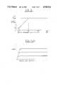
- the AC power produced by the inverter 104has the voltage vs. frequency (v/f) characteristics as shown in FIG. 2, and the rotational speed of the induction motor 105 is controlled on the basis of the v/f characteristics shown.
- the induction motor 105When the inverter 104 produces the output voltage v in proportion to the output frequency f as shown in part of the v/f characteristics of FIG. 2, the induction motor 105 is driven with a constant torque characteristic as shown in FIG. 3(a) and 3(b), or when the inverter 104 produces a constant output voltage v irrespective of variable output frequency f as shown in part of FIG. 2, the induction motor 105 produces a constant output characteristic in a wide speed range.
- the actuator torque controller arranged as described aboveis capable of torque control in the normal operating condition except for the lowest speed range as shown in FIG. 3(a).
- the torque rippleincreases and the output is lacking in a sufficient and stable torque in the lowest speed range and therefore the torque control for the induction motor is difficult in this speed range.
- the output frequency of the inverter 104is under the limit so that the rotational speed control for the actuator is difficult, too.
- the other object of this inventionis to provide a rotational speed control apparatus for a differential actuator consisting of two induction motors and a differential mechanism in combination, wherein the two induction motors are controlled separately by associated inverters so that constant rotational speeds independent of the load torque are obtained on the output shaft of the differential actuator in the speed range from stoppage to the normal operating speed.
- the inventive rotation control apparatus for a differential actuator made up of two induction motors and a differential mechanismcomprises two inverters for supplying power with intended frequencies separately to the induction motors so that the output torque and the rotational speed on the output shaft of the differential actuator are controlled to constant speeds based on the difference of power frequencies set for the inverters.
- One induction motoris driven by the inverter providing a constant output frequency, while the other induction motor is driven by the inverter providing variable output frequencies, whereby both drivers operate in unison to produce a constant output torque in a wide speed range from stoppage to the normal operating speed.
- This operationis based on the differential characteristics of the differential mechanism which is capable of driving its output shaft at a zero speed even though the induction motors rotate at high speeds, and this control scheme is also effective for preventing the occurrence of the torque ripple.
- by setting the arbitrary output frequencies of both invertersit is possible to reverse the output rotation or to change the output torque as desired.
- FIG. 1is a block diagram showing the induction motor control circuit used in the conventional differential actuator rotation controller
- FIG. 2is a graph showing the inverter output voltage vs. frequency characteristics employed in the conventional rotation controller
- FIG. 3(a) and (b)are graphs showing the induction motor output torque vs. speed characteristics of the conventional rotation controller
- FIG. 4is a block diagram showing an embodiment of this invention.
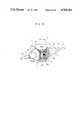
- FIG. 5is a view, substantially in section, partial showing the differential actuator used in the above embodiment
- FIG. 6is partial perspective diagram showing the principal portion of the mechanism shown in FIG. 5;
- FIG. 7is a graph showing the induction motor output torque vs. speed characteristics of the above differential actuator
- FIG. 8(a)is a graph showing the induction motor output torque vs. speed characteristics of the above differential actuator rotation controller plotted when the setting frequency of the inverter is varied;
- FIG. 8(b)is a graph showing the induction motor output torque vs. speed characteristics of the above differential actuator rotation controller plotted when the difference of both frequencies of the driving electric power is controlled by the inverter.
- FIG. 9is a graph showing the induction motor output torque vs. speed characteristics of the differential actuator plotted when the output shaft is loaded.
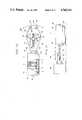
- FIG. 10is a side view of the gripper to which this invention is applied.
- FIG. 11is a side view of the workpiece pushing apparatus to which this invention is applied.
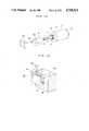
- FIG. 12is a perspective view of the clamper to which this invention is applied.
- FIG. 13is a perspective view of the spindle of the machine tool to which this invention is applied.
- FIG. 14is a perspective view of the joint section of the arm of the industrial robot to which this invention is applied.
- FIG. 15is a perspective view of the conveyer mechanism to which this invention is applied.
- a differential actuator 1is made up of two induction motors 2 and 3 having the same structure and same output characteristics and a differential mechanism 4.
- the induction motors 2 and 3are supplied with power from a common 3-phase AC power source 5 through power lines 6 and 7, respectively, on which are provided two inverters 8 and 9 having the voltage vs. frequency characteristics as described previously using FIG. 2.
- Polyphase power meters 10 and 11are inserted between the induction motor 2 and inverter 8 and between the motor 3 and inverter 9, respectively.
- the differential actuator 1has one output shaft 12 coupled with a digital torque sensor 14 for measuring in digital manner the output torque of the shaft 12, and a torque meter 15 for reading out the measured output torque is attached to the digital torque sensor 14.
- the detailed structure of the differential actuator 1includes, as shown in FIG. 5, a virtually cylindrical case 16, the above-mentioned induction motors 2 and 3 and the differential mechanism 4 all integrated within the case 16, the bonnets 18 which function to close both end openings of the case 16 and also to support bearings 17 of the output shafts 12 and 13.
- the induction motors 2 and 3produce the torque by the electromagnetic induction acting between stators 20 and 30 fixed on the interior wall of the case 16 and rotors 22 and 32 fixed on the external surface of bored axles 21 and 31.
- the axles 21 and 31are supported rotably by bearings 19 secured to the inner flanges 16a of the case 16, and the output shafts 12 and 13 of the differential actuator 1 run through the bore of the axles 21 and 31, respectively, without intervention of rotation with each other.
- the axles 21 and 31are coupled at their central end faces with a first and second bevel gears 42 and 43 of the differential mechanism 4.
- the first and second bevel gears 42 and 43are in engagement with third bevel gears 44 and 45, which are coupled through bearings 46 with a small differential axis 47 integrated with a cylindrical large differential axis as shown also in FIG. 6.
- the large differential axis 48has its external faces fixed to the central ends 12a and 13a of the output shafts 12 and 13, respectively.
- the differential actuator 1operates such that the axles 21 and 31 of the induction motors 2 and 3 are rotated by the electromagnetic induction in the directions shown by the arrows P and Q, respectively, in FIG. 5. It is first assumed that the rotational speed 81 of the axle 21 is higher than that ⁇ 2 of the axle 31, i.e., ⁇ 1> ⁇ 2, and in this case the differential speed causes the third bevel gears 44 and 45 to rotate around the small differential axis 47 and the differential mechanism 4 rotates around the central axis of the first and second bevel gears 42 and 43 as shown by the arrow P (see FIG. 6). Accordingly, the output shafts 12 and 13 also rotate in the direction P, and their rotational speed is as follows. ##EQU1##
- the axle 21has a rotational speed ⁇ 1 which is lower than that ⁇ 2 of the axle 31, i.e., ⁇ 1 ⁇ 2, and in this case the third bevel gears 44 and 45 are rotated by the second bevel gear 43 and the differential mechanism 4 rotates in the direction shown by the arrow Q, as opposed to the previous case. Accordingly, the output shafts 12 and 13 also rotate in the direction Q.
- the output shafts 12 and 13can rotate smoothly and easily from a zero speed to a certain low speed, facilitating the speed change of the differential mechanism 4 in the low-speed range.
- the first caseis that the axle 31 of the induction motor 3 in connection with the second bevel gear 43 of the differential mechanism 4 (FIGS. 5 and 6) is rotated in the same direction P as the axle 21.
- the output shafts 12 and 13have their rotational speed ⁇ o added by the speed of the first and second bevel gears 42 and 43 as follows. ##EQU2##
- the output shafts 12 and 13 of the differential actuator 1have such a wide speed range including a zero speed, and it is expressed as follows. ##EQU3##
- the followingdescribes the method of controlling the output torque of the differential actuator 1 using the circuit shown in FIG. 4.
- An experimentwas conducted for evaluating the speed vs. torque relation of the output shafts 12 and 13 of the differential actuator 1 for the setting frequencies of the inverters 8 and 9 of 35 Hz and 30 Hz, respectively, and the rotational speed of the induction motor 2 of 937 r.p.m, with the result shown by the solid line in FIG. 7.
- the maximum output torquereached 29.6 kg/cm as shown.
- the dashed line in FIG. 7shows the output torque produced by the conventional system where a single induction motor is driven at a setting frequency with the maximum output torque of 4.7 kg/cm.
- the maximum output torque indicated by the solid lineis far greater than that indicated by the dashed line, proving that the inverter controller for the differential actuator 1 produces a sufficient torque even in the lower speed range and it favorably stands up to practical uses.
- FIG. 8(b)shows the result of a performance test conducted using the Prony brake for the inventive differential actuator rotation controller.
- the graphshows that the output shafts 12 and 13 are maintained at a constant target speed against the variation of the load torque applied to the output shafts 12 and 13 by the Prony brake through the adjustment of the differential frequency made by changing concurrently the setting frequencies for the two inverters 8 and 9.
- the induction motors 2 and 3 constituting part of the actuator 1are running at high speeds, causing the output shafts 12 and 13 to produce a sufficiently large torque with an extremely small torque ripple despite the slow speed.
- FIG. 10shows the application of this invention to a gripper 50.
- the differential actuator 1has virtually same structure as described on FIG. 5, and its one output shaft 13 is extended to have a thread section 13a, on which a nut member 51 is engaged.
- the nut member 51is provided with tabs 51a, and similar tabs 18a are provided on the bonnet 18 of the case 16, so that two pairs of arms 52 and 53 are pivoted by pins 18b and 51b on the respective tabs 18a and 51a.
- the arms 52 and 53are linked by a pin 54, which also functions to pivotally link grip arms 55 together with the arms 52 and 53.
- the grip arms 55are provided at their ends with grip plates 56 confronting each other, and the grip plates 56 hold a workpiece 57 in response to the swing motion of the grip arms 55 caused by the linear motion of the nut member 51 due to the rotation of the output shaft 13 of the differential actuator 1.
- the grip mechanism 50by application of the inventive rotation controller and differential actuator 1 enables gripping of the workpiece 57 with a desired force which is easily adjusted to meet various requirements such as the case of holding a soft material. Owing to the characteristics shown in FIG. 9, when the workpiece 57 is in movement, it can be moved from one position to another by being held with a constant grip force irrespective of its moving speed.
- FIG. 11shows the application of this invention to a workpiece pushing mechanism 60 used in various automated machines.
- the differential actuator 1is fixed on the bed 61 by means of a fixture 62, and its output shaft 12 has a thread section 12a on which is engaged a nut member 63.
- the nut member 63has an L-shaped pushing attachment 64, which pushes the workpiece 65 on the bed 61 in the linear motion caused by the rotation of the output shaft 12.
- the linear motion of the pushing member 64can be adjusted by torque control for the output shaft 12 in such a manner as to provide for pushing the workpiece 65 slowly with a large torque and retrieving it to the home position quickly with a small torque. It is also possible to feed the workpiece at a constant speed by using the characteristics shown in FIG. 9.
- FIG. 12shows the application of this invention to a clamp mechanism 70.
- the clamp mechanism 70is coupled at its clamp arm 74 through a key member 75 to the end of one output shaft 12 of the differential actuator 1 which is secured to the base by a fixture 72, so that a workpiece 78 is clamped between a clamp member 76 attached at the end of the clamp arm 74 and a clamp pad 77 on the base.
- the clamp forceis produced by the swing motion of the clamp arm 74 caused by the rotation of the output shaft 12, and it can readily be adjusted through the torque control described above.
- FIG. 13is a perspective view of the machine tool drive unit to which the present invention is applied.
- the differential actuator 1has its output shaft 12 coupled at the end with a spindle 80 by means of a fixture 81. Attached at the top of the spindle 80 is a cutting tool 82 for machining a workpiece 83, which is machined at a constant rotational speed by moving the spindle 80 toward the workpiece 83 at a constant speed through the inventive constant speed control for the output shaft 12 of the differential actuator regardless of the magnitude of load torque.
- FIG. 14shows the application of this invention to an industrial robot.
- the differential actuator 1is used as part of the joint section 87 which links an arm 86 with the robot main body 85.
- the joint section 87includes a U-shape rotary flange 89 with its both ends coupled with the output shaft 12 of the differential actuator 1 which is fixed on the main body 85 by means of a fixture 88.
- the output shaft 12has its rotational speed controlled arbitrarily including stoppage regardless of the load torque applied to the arm 86, whereby the constant speed control for the arm 86 is accomplished.
- FIG. 15shows the application of this invention to a conveyer mechanism.
- the differential actuator 1has its output shaft 12 provided with a thread section 12a, which is in engagement with a hinge section 93a of a supporting board 93 standing at one end of a table 91 having a guide section 92, and the output shaft 12 has its end fixed on one end of a slide member 94 which slides on the guide section 92 along the axis of the output shaft 12.
- a slider section 94ais formed at the bottom of the slide member 94, and a workpiece 95 is placed on the slide member 94.
- the slide member 94can be fed at arbitrary speeds in the speed range from stoppage to the normal operating speed, and the conveyer mechanism 90 movable at constant speed can readily be assembled with a machine tool or the like.
- the inventive rotation control apparatusincorporates two inverters having constant but separate voltage/frequency characteristics placed between two induction motors and the power source for the differential actuator producing the output torque by the differential speed between the two induction motors.
- the rotational speed of both induction motorscan be controlled separately by the associated inverters, whereby the output torque on the shafts of the differential actuator can be controlled stably in the extended speed range from stoppage to the normal operating speed.
- the inventive rotation control apparatus for the differential actuator having two induction motors and a differential mechanismincorporates a speed controller for controlling the rotational speed of both induction motors at individual frequencies so that the actuator output shaft is controlled to constant speeds ranging from stoppage to the normal operating speed based on the difference of speeds of both induction motors, whereby the rotational speed of the output shaft is controlled accurately to desired speeds independently of the magnitude of the load torque applied to the output shaft.
Landscapes
- Engineering & Computer Science (AREA)
- Power Engineering (AREA)
- Control Of Multiple Motors (AREA)
Abstract
Description
To=T1+T2 . . . (4)
Claims (10)
Applications Claiming Priority (4)
| Application Number | Priority Date | Filing Date | Title |
|---|---|---|---|
| JP60-227232 | 1985-10-11 | ||
| JP60-227231 | 1985-10-11 | ||
| JP60227232AJPS6289496A (en) | 1985-10-11 | 1985-10-11 | Differential actuator rotation speed control method |
| JP60227231AJPH061996B2 (en) | 1985-10-11 | 1985-10-11 | Torque control device for differential actuator |
Publications (1)
| Publication Number | Publication Date |
|---|---|
| US4760314Atrue US4760314A (en) | 1988-07-26 |
Family
ID=26527567
Family Applications (1)
| Application Number | Title | Priority Date | Filing Date |
|---|---|---|---|
| US06/905,963Expired - Fee RelatedUS4760314A (en) | 1985-10-11 | 1986-09-11 | Rotation controller for a differential actuator |
Country Status (4)
| Country | Link |
|---|---|
| US (1) | US4760314A (en) |
| EP (1) | EP0219684B1 (en) |
| CA (1) | CA1288131C (en) |
| DE (1) | DE3689352T2 (en) |
Cited By (14)
| Publication number | Priority date | Publication date | Assignee | Title |
|---|---|---|---|---|
| US20050084345A1 (en)* | 2003-10-17 | 2005-04-21 | Frye Randy C. | Dual motor tapping machine |
| US20060087186A1 (en)* | 2004-10-25 | 2006-04-27 | Wasson Ken G | Rotor-stator structure for electrodynamic machines |
| US20060087188A1 (en)* | 2004-10-25 | 2006-04-27 | Petro John P | Rotor-stator structure for electrodynamic machines |
| RU2326489C1 (en)* | 2007-01-09 | 2008-06-10 | ГОУ ВПО "Вологодский государственный технический университет" (ВоГТУ) | Device for high voltage motor control with help of low voltage control circuit |
| US7884522B1 (en) | 2004-10-25 | 2011-02-08 | Novatorque, Inc. | Stator and rotor-stator structures for electrodynamic machines |
| US7982350B2 (en) | 2004-10-25 | 2011-07-19 | Novatorque, Inc. | Conical magnets and rotor-stator structures for electrodynamic machines |
| US20110273126A1 (en)* | 2007-05-28 | 2011-11-10 | Seiko Epson Corporation | Robotic drive control |
| US20120081059A1 (en)* | 2010-10-01 | 2012-04-05 | Bernard Edwin Romig | Electro-mechanical drive with extended constant power speed range |
| US8283832B2 (en) | 2004-10-25 | 2012-10-09 | Novatorque, Inc. | Sculpted field pole members and methods of forming the same for electrodynamic machines |
| US8330316B2 (en) | 2011-03-09 | 2012-12-11 | Novatorque, Inc. | Rotor-stator structures including boost magnet structures for magnetic regions in rotor assemblies disposed external to boundaries of conically-shaped spaces |
| US8471425B2 (en) | 2011-03-09 | 2013-06-25 | Novatorque, Inc. | Rotor-stator structures including boost magnet structures for magnetic regions having angled confronting surfaces in rotor assemblies |
| US8543365B1 (en) | 2004-10-25 | 2013-09-24 | Novatorque, Inc. | Computer-readable medium, a method and an apparatus for designing and simulating electrodynamic machines implementing conical and cylindrical magnets |
| US20140100732A1 (en)* | 2010-07-21 | 2014-04-10 | Superior Electron, Llc | System, architecture, and method for minimizing power consumption and increasing performance in electric vehicles |
| US9093874B2 (en) | 2004-10-25 | 2015-07-28 | Novatorque, Inc. | Sculpted field pole members and methods of forming the same for electrodynamic machines |
Families Citing this family (2)
| Publication number | Priority date | Publication date | Assignee | Title |
|---|---|---|---|---|
| DE3804634A1 (en)* | 1988-02-15 | 1989-08-24 | Bosch Gmbh Robert | Highly dynamic electrical servo drive with a plurality of asynchronous machines |
| US5359154A (en)* | 1989-12-15 | 1994-10-25 | Anritsu Corporation | Conveyor apparatus having plural conveyors with equalized conveying speeds controlled by an inverter means |
Citations (18)
| Publication number | Priority date | Publication date | Assignee | Title |
|---|---|---|---|---|
| US1874094A (en)* | 1926-05-11 | 1932-08-30 | Ford Instr Co Inc | Transmission system |
| US1907132A (en)* | 1930-08-28 | 1933-05-02 | Bell Telephone Labor Inc | Constant frequency system |
| US2578837A (en)* | 1949-04-19 | 1951-12-18 | William E Raney | Variable-speed drive |
| US2678414A (en)* | 1950-11-21 | 1954-05-11 | Aero Materiel Ab | Servomotor |
| US2733391A (en)* | 1952-04-26 | 1956-01-31 | Integrator | |
| US2745016A (en)* | 1952-03-25 | 1956-05-08 | Edwin F Kulikowski | Automatic tuning mechanism |
| US2796565A (en)* | 1952-03-27 | 1957-06-18 | Bendix Aviat Corp | Electrical control system |
| US2890000A (en)* | 1955-09-26 | 1959-06-09 | Beloit Iron Works | Winder drive |
| US2898531A (en)* | 1956-12-31 | 1959-08-04 | Gen Precision Lab Inc | Motor differential frequency integrator |
| US3057572A (en)* | 1960-01-05 | 1962-10-09 | Cameron Machine Co | Winding machine |
| US3164760A (en)* | 1960-10-27 | 1965-01-05 | Westinghouse Brake & Signal | Control for variable speed electrical motor systems |
| US3697763A (en)* | 1971-06-25 | 1972-10-10 | Robert D Middlebrook | Adjustable speed electric power means and system |
| JPS5024661A (en)* | 1973-06-23 | 1975-03-15 | ||
| JPS5267452A (en)* | 1975-12-02 | 1977-06-03 | Tetsuo Matsubara | Stepless speed change gear |
| JPS5427660A (en)* | 1977-08-02 | 1979-03-01 | Hamamatsu Seisakushiyo Kk | Controlling device |
| US4289996A (en)* | 1978-08-29 | 1981-09-15 | Frazer Nash Limited | Actuators |
| JPS59140940A (en)* | 1983-02-01 | 1984-08-13 | Kiichi Taga | Transmission employing defferential and auxiliary electric motor of variable speed |
| US4594652A (en)* | 1984-02-28 | 1986-06-10 | Mattson Evert C | Digital audio differential drive system |
Family Cites Families (3)
| Publication number | Priority date | Publication date | Assignee | Title |
|---|---|---|---|---|
| DE2220686A1 (en)* | 1971-08-11 | 1973-02-22 | Senftenberg Braunkohle | PROCEDURE AND CIRCUIT ARRANGEMENT FOR THE OPTIMAL DRIVING METHOD OF POWERFUL BUCKET CHAIN, PUCKET WHEEL AND CONVEYOR DRIVES OF LARGE OPEN MINING EQUIPMENT |
| BE790711A (en)* | 1971-11-01 | 1973-04-30 | Westinghouse Electric Corp | TWO MOTOR DRIVE SYSTEM |
| DE2337011C2 (en)* | 1973-07-20 | 1982-10-07 | Era Elektronik-Regelautomatik Gmbh & Co Kg, 4800 Bielefeld | Twin-motor drive device for transport equipment |
- 1986
- 1986-09-11USUS06/905,963patent/US4760314A/ennot_activeExpired - Fee Related
- 1986-09-16DEDE86112749Tpatent/DE3689352T2/ennot_activeExpired - Fee Related
- 1986-09-16EPEP86112749Apatent/EP0219684B1/ennot_activeExpired - Lifetime
- 1986-09-18CACA000518547Apatent/CA1288131C/ennot_activeExpired - Lifetime
Patent Citations (18)
| Publication number | Priority date | Publication date | Assignee | Title |
|---|---|---|---|---|
| US1874094A (en)* | 1926-05-11 | 1932-08-30 | Ford Instr Co Inc | Transmission system |
| US1907132A (en)* | 1930-08-28 | 1933-05-02 | Bell Telephone Labor Inc | Constant frequency system |
| US2578837A (en)* | 1949-04-19 | 1951-12-18 | William E Raney | Variable-speed drive |
| US2678414A (en)* | 1950-11-21 | 1954-05-11 | Aero Materiel Ab | Servomotor |
| US2745016A (en)* | 1952-03-25 | 1956-05-08 | Edwin F Kulikowski | Automatic tuning mechanism |
| US2796565A (en)* | 1952-03-27 | 1957-06-18 | Bendix Aviat Corp | Electrical control system |
| US2733391A (en)* | 1952-04-26 | 1956-01-31 | Integrator | |
| US2890000A (en)* | 1955-09-26 | 1959-06-09 | Beloit Iron Works | Winder drive |
| US2898531A (en)* | 1956-12-31 | 1959-08-04 | Gen Precision Lab Inc | Motor differential frequency integrator |
| US3057572A (en)* | 1960-01-05 | 1962-10-09 | Cameron Machine Co | Winding machine |
| US3164760A (en)* | 1960-10-27 | 1965-01-05 | Westinghouse Brake & Signal | Control for variable speed electrical motor systems |
| US3697763A (en)* | 1971-06-25 | 1972-10-10 | Robert D Middlebrook | Adjustable speed electric power means and system |
| JPS5024661A (en)* | 1973-06-23 | 1975-03-15 | ||
| JPS5267452A (en)* | 1975-12-02 | 1977-06-03 | Tetsuo Matsubara | Stepless speed change gear |
| JPS5427660A (en)* | 1977-08-02 | 1979-03-01 | Hamamatsu Seisakushiyo Kk | Controlling device |
| US4289996A (en)* | 1978-08-29 | 1981-09-15 | Frazer Nash Limited | Actuators |
| JPS59140940A (en)* | 1983-02-01 | 1984-08-13 | Kiichi Taga | Transmission employing defferential and auxiliary electric motor of variable speed |
| US4594652A (en)* | 1984-02-28 | 1986-06-10 | Mattson Evert C | Digital audio differential drive system |
Cited By (27)
| Publication number | Priority date | Publication date | Assignee | Title |
|---|---|---|---|---|
| US20050084345A1 (en)* | 2003-10-17 | 2005-04-21 | Frye Randy C. | Dual motor tapping machine |
| US20060145555A1 (en)* | 2004-10-25 | 2006-07-06 | Petro John P | Rotor-stator structure for electrodynamic machines |
| US7982350B2 (en) | 2004-10-25 | 2011-07-19 | Novatorque, Inc. | Conical magnets and rotor-stator structures for electrodynamic machines |
| US7061152B2 (en) | 2004-10-25 | 2006-06-13 | Novatorque, Inc. | Rotor-stator structure for electrodynamic machines |
| US8543365B1 (en) | 2004-10-25 | 2013-09-24 | Novatorque, Inc. | Computer-readable medium, a method and an apparatus for designing and simulating electrodynamic machines implementing conical and cylindrical magnets |
| US20060152099A1 (en)* | 2004-10-25 | 2006-07-13 | Petro John P | Rotor-stator structure for electrodynamic machines |
| US7205693B2 (en) | 2004-10-25 | 2007-04-17 | Novatorque, Inc. | Rotor-stator structure for electrodynamic machines |
| US20060087188A1 (en)* | 2004-10-25 | 2006-04-27 | Petro John P | Rotor-stator structure for electrodynamic machines |
| US8330317B2 (en) | 2004-10-25 | 2012-12-11 | Novatorque, Inc. | Conical magnets and rotor-stator structures for electrodynamic machines |
| US7239058B2 (en) | 2004-10-25 | 2007-07-03 | Novatorque, Inc. | Rotor-stator structure for electrodynamic machines |
| US7884522B1 (en) | 2004-10-25 | 2011-02-08 | Novatorque, Inc. | Stator and rotor-stator structures for electrodynamic machines |
| US7294948B2 (en) | 2004-10-25 | 2007-11-13 | Novatorque, Inc. | Rotor-stator structure for electrodynamic machines |
| US20060087186A1 (en)* | 2004-10-25 | 2006-04-27 | Wasson Ken G | Rotor-stator structure for electrodynamic machines |
| US9093874B2 (en) | 2004-10-25 | 2015-07-28 | Novatorque, Inc. | Sculpted field pole members and methods of forming the same for electrodynamic machines |
| US8283832B2 (en) | 2004-10-25 | 2012-10-09 | Novatorque, Inc. | Sculpted field pole members and methods of forming the same for electrodynamic machines |
| RU2326489C1 (en)* | 2007-01-09 | 2008-06-10 | ГОУ ВПО "Вологодский государственный технический университет" (ВоГТУ) | Device for high voltage motor control with help of low voltage control circuit |
| US20110273126A1 (en)* | 2007-05-28 | 2011-11-10 | Seiko Epson Corporation | Robotic drive control |
| US8471512B2 (en)* | 2007-05-28 | 2013-06-25 | Seiko Epson Corporation | Robotic drive control |
| US20140100732A1 (en)* | 2010-07-21 | 2014-04-10 | Superior Electron, Llc | System, architecture, and method for minimizing power consumption and increasing performance in electric vehicles |
| US9676295B2 (en)* | 2010-07-21 | 2017-06-13 | Superior Electron, Llc | System, architecture, and method for minimizing power consumption and increasing performance in electric vehicles |
| US9855859B2 (en) | 2010-07-21 | 2018-01-02 | Superior Electron, Llc | System, architecture, and method for minimizing power consumption and increasing performance in electric vehicles |
| US10220726B2 (en) | 2010-07-21 | 2019-03-05 | Superior Electron, Llc | System, architecture, and method for minimizing power consumption and increasing performance in electric vehicles |
| US8373375B2 (en)* | 2010-10-01 | 2013-02-12 | Deere & Company | Electro-mechanical drive with extended constant power speed range |
| US8754604B2 (en) | 2010-10-01 | 2014-06-17 | Deere & Company | Electro-mechanical drive with extended constant power speed range |
| US20120081059A1 (en)* | 2010-10-01 | 2012-04-05 | Bernard Edwin Romig | Electro-mechanical drive with extended constant power speed range |
| US8471425B2 (en) | 2011-03-09 | 2013-06-25 | Novatorque, Inc. | Rotor-stator structures including boost magnet structures for magnetic regions having angled confronting surfaces in rotor assemblies |
| US8330316B2 (en) | 2011-03-09 | 2012-12-11 | Novatorque, Inc. | Rotor-stator structures including boost magnet structures for magnetic regions in rotor assemblies disposed external to boundaries of conically-shaped spaces |
Also Published As
| Publication number | Publication date |
|---|---|
| DE3689352D1 (en) | 1994-01-13 |
| DE3689352T2 (en) | 1994-04-14 |
| EP0219684A2 (en) | 1987-04-29 |
| EP0219684A3 (en) | 1989-03-01 |
| CA1288131C (en) | 1991-08-27 |
| EP0219684B1 (en) | 1993-12-01 |
Similar Documents
| Publication | Publication Date | Title |
|---|---|---|
| US4760314A (en) | Rotation controller for a differential actuator | |
| US5327790A (en) | Reaction sensing torque actuator | |
| US5614799A (en) | Brushless direct current motor having adjustable motor characteristics | |
| EP1894683A1 (en) | Industrial robot | |
| EP0195393B1 (en) | Differential actuator | |
| KR101956743B1 (en) | A test rig and a method for testing gearboxes having different gear ratios | |
| JP3556709B2 (en) | Method and apparatus for synchronous operation of servo motor | |
| Makino et al. | Motion control of the direct drive actuator | |
| CN112207331A (en) | A Dynamic Integrated Modeling Method for Milling Process of Single-axis Feed System | |
| CN112199821A (en) | Electromechanical combined modeling method for motion characteristics of single-shaft ball screw feeding system | |
| Whalley et al. | The axes response and resonance identification for a machine tool | |
| Pham | Position control of cartesian robot | |
| Hayashida et al. | A friction compensation in twin drive system | |
| Williams | Direct drive system for an industrial robot using a brushless DC motor | |
| CN222966818U (en) | High-rigidity dual-motor complementary power shaft device | |
| Williams et al. | Design philosophy of an isotropic six-axis serial manipulator | |
| Bassi et al. | A mechanical simulator for testing and evaluating electrical drives for robotics applications | |
| Yılmaz | Analysis and Modeling of an Actuation System to be used in Light-weight Collaborative Robots | |
| KR900002423B1 (en) | Torque control method of differential actuator | |
| JP2908261B2 (en) | Method for suppressing torsional vibration and twin drive control device | |
| Wang | Directional impedance of geared transmissions | |
| EP0017403A1 (en) | A method of, and apparatus for, operating an induction motor | |
| JPH0811079A (en) | Drive part of industrial robot | |
| JPS627425B2 (en) | ||
| Bu et al. | Design of Position Control System for Magnetic Lead Screw-Based Radial-Gap Rotary-Linear Two-Degree-of-Freedom Actuator |
Legal Events
| Date | Code | Title | Description |
|---|---|---|---|
| AS | Assignment | Owner name:MOHRI, NAOTAKE, 3837-3, SHIMADA KUROISHI, TENPAKUC Free format text:ASSIGNMENT OF ASSIGNORS INTEREST.;ASSIGNORS:MOHRI, NAOTAKE;SAITO, NAGAO;YANAI, YOSHIHIKO;AND OTHERS;REEL/FRAME:004599/0642 Effective date:19860902 Owner name:MITSUBISHI DENKI KABUSHIKI KAISHA Free format text:ASSIGNMENT OF ASSIGNORS INTEREST.;ASSIGNORS:MOHRI, NAOTAKE;SAITO, NAGAO;YANAI, YOSHIHIKO;AND OTHERS;REEL/FRAME:004599/0642 Effective date:19860902 Owner name:MOHRI, NAOTAKE,JAPAN Free format text:ASSIGNMENT OF ASSIGNORS INTEREST;ASSIGNORS:MOHRI, NAOTAKE;SAITO, NAGAO;YANAI, YOSHIHIKO;AND OTHERS;REEL/FRAME:004599/0642 Effective date:19860902 Owner name:MITSUBISHI DENKI KABUSHIKI KAISHA,STATELESS Free format text:ASSIGNMENT OF ASSIGNORS INTEREST;ASSIGNORS:MOHRI, NAOTAKE;SAITO, NAGAO;YANAI, YOSHIHIKO;AND OTHERS;REEL/FRAME:004599/0642 Effective date:19860902 | |
| CC | Certificate of correction | ||
| FPAY | Fee payment | Year of fee payment:4 | |
| FPAY | Fee payment | Year of fee payment:8 | |
| REMI | Maintenance fee reminder mailed | ||
| LAPS | Lapse for failure to pay maintenance fees | ||
| FP | Lapsed due to failure to pay maintenance fee | Effective date:20000726 | |
| STCH | Information on status: patent discontinuation | Free format text:PATENT EXPIRED DUE TO NONPAYMENT OF MAINTENANCE FEES UNDER 37 CFR 1.362 |