US4759366A - Rate responsive pacing using the ventricular gradient - Google Patents
Rate responsive pacing using the ventricular gradientDownload PDFInfo
- Publication number
- US4759366A US4759366AUS06/841,517US84151786AUS4759366AUS 4759366 AUS4759366 AUS 4759366AUS 84151786 AUS84151786 AUS 84151786AUS 4759366 AUS4759366 AUS 4759366A
- Authority
- US
- United States
- Prior art keywords
- peak
- pacing rate
- time interval
- pacing
- rate
- Prior art date
- Legal status (The legal status is an assumption and is not a legal conclusion. Google has not performed a legal analysis and makes no representation as to the accuracy of the status listed.)
- Expired - Lifetime
Links
- 230000002861ventricularEffects0.000titleclaimsdescription15
- 230000000747cardiac effectEffects0.000claimsabstractdescription47
- 230000000763evoking effectEffects0.000claimsabstractdescription27
- 230000004044responseEffects0.000claimsabstractdescription24
- 230000002336repolarizationEffects0.000claimsabstractdescription19
- 230000028161membrane depolarizationEffects0.000claimsabstractdescription16
- 238000000034methodMethods0.000claimsdescription18
- 230000003247decreasing effectEffects0.000claimsdescription10
- 230000002401inhibitory effectEffects0.000claims4
- 210000001308heart ventricleAnatomy0.000abstractdescription4
- 102100026827Protein associated with UVRAG as autophagy enhancerHuman genes0.000description14
- 101710102978Protein associated with UVRAG as autophagy enhancerProteins0.000description14
- 230000002269spontaneous effectEffects0.000description10
- 230000007423decreaseEffects0.000description9
- 238000001514detection methodMethods0.000description8
- 238000010586diagramMethods0.000description8
- 230000000694effectsEffects0.000description8
- 230000000638stimulationEffects0.000description8
- 230000008859changeEffects0.000description7
- 239000004020conductorSubstances0.000description5
- 230000010354integrationEffects0.000description4
- 230000036279refractory periodEffects0.000description4
- 230000001746atrial effectEffects0.000description2
- 230000002902bimodal effectEffects0.000description2
- 230000008602contractionEffects0.000description2
- 230000001419dependent effectEffects0.000description2
- 230000006870functionEffects0.000description2
- 210000002837heart atriumAnatomy0.000description2
- 230000007774longtermEffects0.000description2
- 238000004519manufacturing processMethods0.000description2
- 206010015856ExtrasystolesDiseases0.000description1
- RTAQQCXQSZGOHL-UHFFFAOYSA-NTitaniumChemical compound[Ti]RTAQQCXQSZGOHL-UHFFFAOYSA-N0.000description1
- 208000009729Ventricular Premature ComplexesDiseases0.000description1
- 206010047289Ventricular extrasystolesDiseases0.000description1
- 239000000956alloySubstances0.000description1
- 229910045601alloyInorganic materials0.000description1
- 230000008901benefitEffects0.000description1
- 239000008280bloodSubstances0.000description1
- 210000004369bloodAnatomy0.000description1
- 239000003990capacitorSubstances0.000description1
- 230000011128cardiac conductionEffects0.000description1
- 230000009989contractile responseEffects0.000description1
- 230000008878couplingEffects0.000description1
- 238000010168coupling processMethods0.000description1
- 238000005859coupling reactionMethods0.000description1
- 239000013078crystalSubstances0.000description1
- 238000013461designMethods0.000description1
- 230000003292diminished effectEffects0.000description1
- 230000009977dual effectEffects0.000description1
- 238000002513implantationMethods0.000description1
- 230000006872improvementEffects0.000description1
- 230000000977initiatory effectEffects0.000description1
- 238000002955isolationMethods0.000description1
- 238000005259measurementMethods0.000description1
- 229910052751metalInorganic materials0.000description1
- 239000002184metalSubstances0.000description1
- 230000004048modificationEffects0.000description1
- 238000012986modificationMethods0.000description1
- 238000012544monitoring processMethods0.000description1
- 230000004118muscle contractionEffects0.000description1
- 230000002107myocardial effectEffects0.000description1
- 210000004165myocardiumAnatomy0.000description1
- 230000037361pathwayEffects0.000description1
- 230000037081physical activityEffects0.000description1
- HWLDNSXPUQTBOD-UHFFFAOYSA-Nplatinum-iridium alloyChemical compound[Ir].[Pt]HWLDNSXPUQTBOD-UHFFFAOYSA-N0.000description1
- 230000010287polarizationEffects0.000description1
- 230000008569processEffects0.000description1
- 238000000718qrs complexMethods0.000description1
- 230000009467reductionEffects0.000description1
- 230000035945sensitivityEffects0.000description1
- 238000006467substitution reactionMethods0.000description1
- 239000010936titaniumSubstances0.000description1
- 229910052719titaniumInorganic materials0.000description1
Images


Classifications
- A—HUMAN NECESSITIES
- A61—MEDICAL OR VETERINARY SCIENCE; HYGIENE
- A61N—ELECTROTHERAPY; MAGNETOTHERAPY; RADIATION THERAPY; ULTRASOUND THERAPY
- A61N1/00—Electrotherapy; Circuits therefor
- A61N1/18—Applying electric currents by contact electrodes
- A61N1/32—Applying electric currents by contact electrodes alternating or intermittent currents
- A61N1/36—Applying electric currents by contact electrodes alternating or intermittent currents for stimulation
- A61N1/362—Heart stimulators
- A61N1/37—Monitoring; Protecting
- A61N1/371—Capture, i.e. successful stimulation
- A61N1/3712—Auto-capture, i.e. automatic adjustment of the stimulation threshold
- A—HUMAN NECESSITIES
- A61—MEDICAL OR VETERINARY SCIENCE; HYGIENE
- A61N—ELECTROTHERAPY; MAGNETOTHERAPY; RADIATION THERAPY; ULTRASOUND THERAPY
- A61N1/00—Electrotherapy; Circuits therefor
- A61N1/18—Applying electric currents by contact electrodes
- A61N1/32—Applying electric currents by contact electrodes alternating or intermittent currents
- A61N1/36—Applying electric currents by contact electrodes alternating or intermittent currents for stimulation
- A61N1/362—Heart stimulators
- A61N1/365—Heart stimulators controlled by a physiological parameter, e.g. heart potential
- A61N1/36507—Heart stimulators controlled by a physiological parameter, e.g. heart potential controlled by gradient or slope of the heart potential
Definitions
- An implantable cardiac pacercan have various pacing modes as well as various output parameters such as rate, output level, voltage, pulse width, sensitivity, refractory period, etc.
- both the modee.g, R-wave inhibited VVI, as well as the various output parameters, are preset during production, whereas in other cardiac pacers either mode or output parameters or both can be altered by external control or programming.
- Such output parameters and/or pacing mode changesare usually accomplished by the attending physician, usually during an office visit. Therefore, such cardiac pacers may not be responsive to the physiological requirements of the patients. Such requirements fluctuate often during a 24-hour period, certainly more frequently than the interval between patient's visits to the physician. Thus the patient must suffer less than optimum heart pacing.
- physiological parameterscan include activity of the patient (Dahl U.S. Pat. No. 4,140,132), sensed ionic changes (Wirtzfeld U.S. Pat. No. 4,202,339), the patient's threshold, i.e., the level of a stimulus pulse required to evoke a resulting heartbeat when the pulse is delivered to the patient's heart (Wittkampf, et al. U.S. Pat. No. 4,305,396), and the stimulus to repolarization of the T-wave interval (Rickards U.S. Pat. No. 4,228,803).
- the detection of such changesis utilized either to increase or to decrease the rate of stimulation.
- Measurement of physical activity or of the ionic level in the blooddoes not appear to measure the effectiveness of the pulse emitted from the cardiac pacer initiating myocardial contraction.
- the amplitude, as measured from the base line, of the repolarization potential or T-wavetends to be low, thereby posing problems in detection.
- a time period or "window" for sensing of the T-wavemust be established and programmed either at manufacture or after implantation. If there is an improper setting of the sensing window, the T-wave may not be sensed.
- the T-wavemay be bimodal; that is, there may be two peaks rather than one. It is possible that the amplitude of the first peak is not sufficient to be detected, and that the second peak may be outside of the sensing window. Alternatively, neither of the peaks of the bimodal T-wave may be of sufficient amplitude to be detected.
- a more reliable technique for detecting stress level changesis provided, particularly in a paced heart where it is desirable to provide feedback means so that the rate of pacing of the heart can vary in a manner responsive to heart stress. Improvements of long term reliability and ease of operation are provided by this invention.
- a systemfor applying electrical stimulus pulses to the heart in a manner that is at least partially controlled by stress level changes. Electrical stimulus pulses are applied to pace the heart at a rate which is at least partially dependent on the stress level changes so determined, to provide a heart pacing system which is responsive in terms of causing a changed heartbeat rate in response to changes in stress levels of the heart. This, in turn, provides greater patient comfort and greater ability for the patient to lead a normal life, engaging in a greater range of activities calling for different pulse rates.
- a systemfor detecting in at least one cardiac cycle, the changing voltage of the cardiac ventricle during the QRST phase of the cycle; followed by integrating the changing voltage over time from essentially the Q-point to the S-point to obtain the depolarization gradient, and from the Q-point to the T-point to obtain the repolarization gradient.
- the systemdetermines the peak to peak time interval from the peak of the depolarization gradient to the peak of the repolarization gradient.
- the peak to peak time interval of one cardiac cyclei.e., heartbeat
- a change in the value of the peak to peak time intervalis an indication of a change in heartbeat stress level.
- the changesare inversely dependent upon stress in the heart: an increase in the peak to peak time interval indicates a decrease in heart stress, while a decrease in the peak to peak time interval indicates an increase in heart stress. Accordingly, when the peak to peak time interval is sensed to increase in a pacing system, means are provided to decrease the pacing rate to decrease the heartbeat and heart output. Conversely, when the peak to peak time interval decreases, it is an indication of more stress and the pacing system increases the heartbeat in response. When the peak to peak time interval remains the same, it is an indication that there is no change in stress.
- the systemmay compare parameters of the QRS complex which indicate heart stress against a target value which has been determined by the medical history of the patient. For example, the system may determine the peak to peak time interval of at least one heartbeat and then compare the peak to peak time interval obtained with such target value. If the peak to peak time interval is greater than the target value, the system may decrease the rate of electrical stimuli admitted by the heart pacer. If the peak to peak time interval is less than the target value, the system may increase the rate of such electrical stimuli.
- a patient having a paced heartis no longer limited to a single electric stimulus rate from visit to visit to the doctor's office to adjust such rate. If he climbs a hill or a flight of stairs, his pacer stimulus rate will increase. When he goes to bed, his stimulus rate will decrease.
- patients who are equipped with pacers controlled in accordance with this inventioncan have a lifestyle which is much closer to normal than in previous pacer systems.
- ventricular gradientis independent of the origin of heart stimulation. Hence, naturally conducted beats, paced beats, and ectopic beats can all yield heart stress information by the comparison of ventricular gradients of a present heartbeat with an earlier heartbeat in accordance with this invention.
- sensing of the changing voltage of the heart ventricleprovides more meaningful data than sensing voltage changes of other portions of the heart, although the system may also sense in accordance with this invention from the atrium.
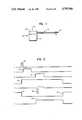
- FIG. 1is an elevational view of a cardiac pacing system with a bipolar lead which functions both as a unipolar and a bipolar system at different steps of the operating cycle;
- FIG. 2is a timing diagram of the relationship of the electronic events which take place during a single cardiac cycle
- FIG. 3is a schematic block diagram of a single chamber cardiac pacer with evoked potential monitoring and an integrating circuit
- FIG. 4is a schematic block diagram of the charge dump circuit used herein;
- FIG. 5is a diagram of the evoked potential over time sensed by a pacer and lead of FIG. 1 positioned at a heart ventricle;
- FIG. 6is a diagram showing the integrated value of the evoked potential of FIG. 5, in horizontal time synchronization with FIG. 5;
- FIG. 7is a schematic diagram of a pacer system constructed in accordance with the present invention.
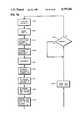
- FIGS. 8a and 8bwhen connected together, comprise a flow chart depicting the operation of the diagram of FIG. 7;
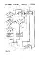
- FIGS. 9a and 9bwhen connected together, comprise a flow chart depicting the operation of another embodiment of the invention.
- a single chamber cardiac pacing system 10includes pulse generator 12, which may be of generally conventional electronics except as otherwise described herein.
- Pervenous bipolar lead 14is also provided and may be of conventional bipolar pervenous or epicardial design.
- First electrode 16may be a porous, platinum-iridium, hemispherically shaped electrode on the distal end of lead 14, communicating with a metal conductor inside of the lead.
- Ring electrode 18serves as a second electrode, being capable of electrical isolation by means of the circuitry and pulse generator 12 from first electrode 16, and being typically spaced at least 0.5 cm. from first electrode 16.
- Second, ring-shaped electrode 18may also be made of the same alloy and may communicate with its own circuit wire within lead 14 and may or may not be porous-coated.
- the circuitry of pulse generator 12may be sealed in a hermetic container, for example, titanium can 20, as shown.
- the pacer can 20is treated as an independent electrode, the single chamber cardiac pacing system 10 carries three electrodes: can 20, first electrode 16 and second electrode 18.
- the operation of the pacing system as describedapplies to both the atrial and ventricular leads of a dual chamber cardiac pacer or an atrial standby pacer. However, for purposes of simplicity of disclosure, the details of operation will be disclosed for only a ventricular pacer.
- Herscovici U.S. Pat. No. 4,543,956and to the evoked potential detection and pacing system disclosed in copending U.S. application Ser. No. 807,547, filed Dec. 11, 1985, in the names of Frank J. Callaghan and Edward A. Schroeppel, and entitled "Detection Of Cardiac Evoked Potentials.”
- Cardiac pacing system 10may be external or surgically installed into the patient, and may operate to pace the patient's heart as follows:
- a pacing cyclebegins when an electrical stimulus is emitted from first electrode 16 to stimulate muscular contraction of at least a portion of the heart.
- the stimulusis of a magnitude and width which is not harmful to the heart and which is well-known to those skilled in the art to evoke a contraction response from the heart muscle.
- the pulse of electric stimulus 30is graphed in FIG. 2 at channel A, having a typical duration of 0.1 to 2 milliseconds.
- pacer can 20serving as a reference electrode for electrodes 16, 18, carried at the heart 21 which is shown in schematic manner.
- Stimulus 30is transmitted via conductor 22 to be emitted from tip electrode 16.
- the naturally occurring cardiac electrical activityis amplified by amplifier 44 and transmitted via line 31 to a spontaneous event detector 46 to begin a timing process.
- the signalproceeds via conductor 26 into timing and control circuitry module 50 which, in turn, has feedback and control wires 28, 29 connected, respectively, to detector 46 and to evoked response detector 54.
- an output from timing and control circuit 50is connected via line 35 to output and charge dump circuit 48.
- charge dump circuit 48Immediately following the emission of pulse 30 from electrode 16, charge dump circuit 48 is activated, with the charge dump pulse 34 being illustrated on channel B of FIG. 2, the duration of the charge dump being about 5 to 15 milliseconds.
- the charge dumpmay be provided using a conventional charge dump circuit 48 such as illustrated in FIG. 4.
- the electrical charge on output coupling capacitor 60 (FIG. 4) and first electrode 16are discharged through the heart 21.
- the post-stimulus polarization potential of electrode 16is quickly diminished.
- Evoked response detector 54is then activated by timing and control circuit 50 through conductor 29.
- a window of time 36is opened as illustrated in channel C of FIG. 2, its magnitude being typically 10 to 50 milliseconds. It is only during this time that evoked response detector 54 is activated to detect an evoked electrical response from the heart and to indicate a contractile response to the physiological pulse of electric potential 30.
- the stimulus from electrode 16can be seen to be in the unipolar mode.
- detection of the evoked responseis unipolar, being detected by electrode 18, which communicates through conductor 72 to amplifier 52, which sends the amplified signal to detector 54.
- Detector 54transmits the detected signal via line 55 to integration circuit 57.
- the integrated signalwhich is discussed in detail below, is transmitted to timing and control circuit 50 via line 59.
- the window of time 36 on channel C of FIG. 2is positioned in a block of time 32 (channel D of FIG. 2) which generally represents a refractory period in which first electrode 16 may not be used to sense any electrical activity.
- the evoked responsecan be detected during a refractory period 32.
- Channel E in FIG. 2shows the evoked cardiac electrical activity 38 within evoked response detection period 36, and which is detected by second electrode 18.
- the evoked heartbeat response 38is detected by second electrode 18 in the unipolar mode.
- the detected evoked responsewhich is fed via line 55 to integration circuit 57 and via line 59 to timing and control circuit 50 may serve to set the timer to zero for timing the next physiological pulse to be emitted from first electrode 16.
- an alert period 40(channel F; FIG. 2) is provided to monitor a naturally occurring cardiac electrical activity until such time as the next pulse 30 is sent out through first electrode 16.
- Alert circuitry 46may be activated and shut down by timing and control circuit 50 via line 28.
- a signalmay be sent from spontaneous event detector 46 via line 26 to timing and control circuit 50, to cause the electronics to recycle from any time in the cycle to the beginning of the cycle, without generation of an electric pulse 30 from first electrode 16. Every time natural cardiac electrical activity takes place during alert period 40, no electric pulse 30 will be generated.
- timing and control circuit 50will cause another electric pulse to be generated via electrode 16.
- a typical cardiograph tracing of the changing potential in the ventricle of a heartis shown throughout most of a single cardiac cycle with respect to a reference base line of a predetermined voltage, typically zero volts.
- the Q-pointrepresents the beginning of the R-wave 152 where the voltage trace crosses or is closest to baseline 154, prior to forming R-wave 152.
- the R-pointis the peak of R-wave 152, irrespective of whether the trace is shown in its form of FIG. 5 or in inverted form, which is possible with other recording systems.
- the S-pointis where the trace crosses base line 154.
- the evoked potentialis detected on ring electrode 18.
- the signalis transmitted via heart amplifier 52 and detector 54 to integration circuit 57 via line 55.
- the integrated signal 140is known as the ventricular gradient, and is illustrated in FIG. 6.
- the ventricular gradient 140has a depolarization gradient 141 which is the waveform from point 143 at the baseline 154 to peak 148.
- the magnitude of the depolarization gradientis identified by reference numeral 162.
- the repolarization gradientincludes portion 147 of the waveform shown in FIG. 6.
- the magnitude of the repolarization gradientis identified by reference numeral 151 and the time interval from the peak 148 of the depolarization gradient 141 to the peak 149 of the repolarization gradient 147 is identified by reference numeral 153.
- the peak to peak time interval 153is thus calculated and compared to the peak to peak time interval of a response detected prior to this one.
- the average time of three (or some predetermined number of) peak to peak time intervalsmay be used. In this case, each response should change in the same direction. If the peak to peak time interval 153 is equal to the previous value, there is no change in the heart pacing stimulus rate. The escape interval remains the same. If the peak to peak time interval 153 is shorter than the prior value and there has been a change in the same direction of the three (or some other predetermined number) peak to peak time intervals, a determination is made as to whether or not the stimulus rate is at its programmed maximum rate. If it is at its maximum rate, the peak to peak time interval is stored and the stimulus rate is not increased. However, if the stimulus rate is less than the programmed maximum rate, the rate is incremented by some predetermined value, and the peak to peak time interval is stored for reference at the next subsequent integrated evoked heart response.
- the determinationis made as to whether or not the rate of stimulation is at its minimum programmed rate. If it is at the programmed minimum rate, the peak to peak time interval is stored with no decrease in rate. If it is not at its minimum programmed rate, the rate of the stimulation is decreased by some predetermined value, and the peak to peak time interval is stored for future reference.
- spontaneous electrical eventssuch as those conducted from the atrium to the ventricle via the cardiac conduction pathway or those arising within the ventricle itself, and premature ventricular contractions are detected bipolarly by the ring and tip. These signals are amplified by the amplifier 44 and detected in the spontaneous event detector 46. The timing and control circuit 50 acts upon these events to reset the escape interval. Further, these spontaneous electrical events may be integrated if desired, and the peak to peak time interval 153 may be determined. Rate changes or escape interval changes may be implemented based on the peak to peak time interval of spontaneous electrical events in the same manner that they are implemented based on the peak to peak time interval of the evoked potentials. To this end, the integration circuit 57 of FIG. 3 is shown as receiving the signal from the spontaneous event detector 46 via line 160.
- Timing and control circuit 50comprises a microcomputer 190 which addresses a memory 192 via address bus 194.
- Data bus 196is coupled between microcomputer 190 and memory 192, and conventional control logic 198 is coupled to data bus 196.
- a crystal controlled clock 200is used for providing appropriate clock pulses for the system. The functions of the control logic inputs and outputs are designated.
- Control logic circuit 198provides a gradient measure enable signal to electronic switch 202 and to analog to digital converter 204 which is at the output of an integrating amplifier 206. It can be seen that the output of the amplified potential sensed at ring 18 is applied to the negative input of integrating amplifier 206 which, when enabled, provides an amplified analog output that is converted to digital data by means of analog to digital converter 204.
- the digital datacontains the ventricular gradient information, which is provided to the control logic circuit 198 whereby appropriate timing of the stimulation pulses is achieved in response thereto.
- the gradient measure enable signal 210is illustrated in channel G on FIG. 2. It commences at the same time that the capture detection window 36 commences and the gradient measure enable signal 210 continues for several hundred milliseconds.
- FIGS. 8a-8bA flow chart illustrating the operation of the circuit of FIG. 7 is presented as FIGS. 8a-8b.
- the cyclestarts with a stimulation pulse 30 being emitted (220).
- the evoked response window 36commences (224) and the evoked response amplifier and detector is enabled (226).
- the gradient measure enable signal 210also commences and the evoked response is integrated (228).
- the negative peak 148 of the integral 140is determined (230).
- the positive peak 149 of integral 140is then determined (231).
- the time interval 153 between peak 148 and peak 149is then determined (232).
- the peak to peak time interval 153is then compared (234) with the previous peak to peak time interval 153.
- the pacing ratei.e., cycle length
- the peak to peak time interval 153is stored (240). If they are not equal (242), a determination is made (244) whether the peak to peak time interval 153 is greater than the previous peak to peak time interval 153. If it is greater (246), a determination (248) is made whether the pacing rate is at its minimum. If it is at its minimum, there will be no further change in pacing rate (238) and the peak to peak time interval 153 will be stored (240). If it is not at its minimum (250), a determination (251) will be made with respect to decreasing the present pacing rate, and the peak to peak time interval 153 is stored (252). A new decreased pacing rate (i.e., increased cycle length) is determined (254) and stored (256).
- the present peak to peak time interval 153is not equal to its previous value (242) and is also not greater than its previous value (258), this indicates that the present peak to peak time interval 153 is less than the previous peak to peak time interval 153.
- a determinationis then made whether the pacing rate is at its maximum (260) and if it is at its maximum (262), the cycle length is not changed (238) and the peak to peak time interval 153 is stored (240). If the pacing rate is not at its maximum (264), a determination (266) is made with respect to the decrement in the cycle length (i.e., the increase in pacing rate) and the peak to peak time interval 153 is stored (252). A determination (254) is then made with respect to the new increased pacing rate (i.e., decreased cycle length) and this information is stored.
- FIGS. 9a-9billustrate the operation of the circuit of FIG. 7 when the peak to peak time interval is compared against a target value instead of being compared against the previous value of duration 153.
- the operation of the circuitis identical to the operation of the FIGS. 8a-8b circuit except that instead of comparing duration 153 with the previous value of duration 153, duration 153 is compared against the target value which has been determined by the medical history of the patient.
Landscapes
- Health & Medical Sciences (AREA)
- Cardiology (AREA)
- Heart & Thoracic Surgery (AREA)
- Life Sciences & Earth Sciences (AREA)
- Radiology & Medical Imaging (AREA)
- Nuclear Medicine, Radiotherapy & Molecular Imaging (AREA)
- Biomedical Technology (AREA)
- Engineering & Computer Science (AREA)
- Animal Behavior & Ethology (AREA)
- General Health & Medical Sciences (AREA)
- Public Health (AREA)
- Veterinary Medicine (AREA)
- Biophysics (AREA)
- Physiology (AREA)
- Electrotherapy Devices (AREA)
Abstract
Description
Claims (16)
Priority Applications (3)
| Application Number | Priority Date | Filing Date | Title |
|---|---|---|---|
| US06/841,517US4759366A (en) | 1986-03-19 | 1986-03-19 | Rate responsive pacing using the ventricular gradient |
| DE19873787186DE3787186T2 (en) | 1986-03-19 | 1987-02-10 | Clock-sensitive stimulation using the ventricular gradient. |
| EP19870101814EP0237767B1 (en) | 1986-03-19 | 1987-02-10 | Rate responsive pacing using the ventricular gradient |
Applications Claiming Priority (1)
| Application Number | Priority Date | Filing Date | Title |
|---|---|---|---|
| US06/841,517US4759366A (en) | 1986-03-19 | 1986-03-19 | Rate responsive pacing using the ventricular gradient |
Publications (1)
| Publication Number | Publication Date |
|---|---|
| US4759366Atrue US4759366A (en) | 1988-07-26 |
Family
ID=25285090
Family Applications (1)
| Application Number | Title | Priority Date | Filing Date |
|---|---|---|---|
| US06/841,517Expired - LifetimeUS4759366A (en) | 1986-03-19 | 1986-03-19 | Rate responsive pacing using the ventricular gradient |
Country Status (1)
| Country | Link |
|---|---|
| US (1) | US4759366A (en) |
Cited By (153)
| Publication number | Priority date | Publication date | Assignee | Title |
|---|---|---|---|---|
| US4955376A (en)* | 1988-03-25 | 1990-09-11 | Teletronics N.V. | Pacemaker with improved automatic output regulation |
| US4969460A (en)* | 1988-03-25 | 1990-11-13 | Telectronics N.V. | Pacemaker with improved automatic output regulation |
| US4969462A (en)* | 1988-03-25 | 1990-11-13 | Telectronics N.V. | Pacemaker with improved automatic output regulation |
| US4969464A (en)* | 1988-03-25 | 1990-11-13 | Telectronics N.V. | Pacemaker with improved automatic output regulation |
| US4969467A (en)* | 1988-03-25 | 1990-11-13 | Telectronics N.V. | Pacemaker with improved automatic output regulation |
| US5184615A (en)* | 1991-03-08 | 1993-02-09 | Telectronics Pacing Systems, Inc. | Apparatus and method for detecting abnormal cardiac rhythms using evoked potential measurements in an arrhythmia control system |
| US5197480A (en)* | 1990-06-08 | 1993-03-30 | Vitatron Medical, B.V. | System and method for monitoring heart transplant rejection |
| US5228437A (en)* | 1991-05-06 | 1993-07-20 | Intermedics Orthopedics, Inc. | Cardiac pacemaker and method for detecting cardiac signals |
| US5233985A (en)* | 1990-08-10 | 1993-08-10 | Medtronic, Inc. | Cardiac pacemaker with operational amplifier output circuit |
| US5265603A (en)* | 1990-12-12 | 1993-11-30 | Medtronic, Inc. | Electronic capture detection for a pacer |
| US5271393A (en)* | 1991-05-06 | 1993-12-21 | Telectronics Pacing Systems, Inc. | Pacemaker employing antitachyarrhythmia prevention based on ventricular gradient |
| US5312452A (en)* | 1992-11-03 | 1994-05-17 | Cardiac Pacemakers, Inc. | Cardiac rhythm management device with automatic optimization of performance related pacing parameters |
| US5336244A (en)* | 1992-10-07 | 1994-08-09 | Medtronic, Inc. | Temperature sensor based capture detection for a pacer |
| US5342406A (en)* | 1992-10-07 | 1994-08-30 | Medtronic, Inc. | Oxygen sensor based capture detection for a pacer |
| US5348021A (en)* | 1992-03-31 | 1994-09-20 | Incontrol, Inc. | Apparatus and method for reliably detecting a depolarization activation wave of the heart and atrial defibrillator utilizing same |
| US5391192A (en)* | 1994-03-04 | 1995-02-21 | Telectronics Pacing Systems, Inc. | Automatic ventricular pacing pulse threshold determination utilizing an external programmer and a surface electrocardiogram |
| US5431693A (en)* | 1993-12-10 | 1995-07-11 | Intermedics, Inc. | Method of verifying capture of the heart by a pacemaker |
| US5443485A (en)* | 1993-09-08 | 1995-08-22 | Intermedics, Inc. | Apparatus and method for capture detection in a cardiac stimulator |
| US5782876A (en)* | 1996-04-15 | 1998-07-21 | Medtronic, Inc. | Method and apparatus using windows and an index value for identifying cardic arrhythmias |
| US5861013A (en)* | 1997-04-29 | 1999-01-19 | Medtronic Inc. | Peak tracking capture detection circuit and method |
| US5871512A (en)* | 1997-04-29 | 1999-02-16 | Medtronic, Inc. | Microprocessor capture detection circuit and method |
| US5954756A (en)* | 1998-04-09 | 1999-09-21 | Medtronic, Inc. | Microprocessor capture detection circuit and method |
| US6188927B1 (en) | 1999-04-16 | 2001-02-13 | Pacesetter, Inc. | Implantable cardiac stimulation system having improved method of calibrating physiologic sensors |
| US6377844B1 (en) | 1999-03-13 | 2002-04-23 | Dave Graen | R-wave detector circuit for sensing cardiac signals |
| WO2002051497A2 (en) | 2000-12-27 | 2002-07-04 | Medtronic, Inc. | Leadless fully automatic pacemaker follow-up |
| US20030153953A1 (en)* | 2002-02-14 | 2003-08-14 | Euljoon Park | Stimulation device for sleep apnea prevention, detection and treatment |
| US20040002741A1 (en)* | 2002-06-26 | 2004-01-01 | Weinberg Lisa P. | System and method for tracking progression of left ventricular dysfunction using implantable cardiac stimulation device |
| US20040158292A1 (en)* | 2003-02-06 | 2004-08-12 | Medtronic, Inc. | Methods and apparatus for detecting ventricular depolarizations during atrial pacing |
| US6788970B1 (en) | 2000-04-05 | 2004-09-07 | Pacesetter, Inc. | System and method for treating vasovagal syncope using cardiac pacing |
| US20040220483A1 (en)* | 2003-01-22 | 2004-11-04 | Samsung Electronics Co., Ltd. | Method and apparatus for evaluating human stress using photoplethysmography |
| US20040267321A1 (en)* | 2003-06-26 | 2004-12-30 | Peter Boileau | Method and apparatus for monitoring drug effects on cardiac electrical signals using an implantable cardiac stimulation device |
| US6876882B1 (en)* | 1999-08-05 | 2005-04-05 | St. Jude Medical Ab | Cardiac stimulating device |
| US6904320B2 (en) | 2002-02-14 | 2005-06-07 | Pacesetter, Inc. | Sleep apnea therapy device using dynamic overdrive pacing |
| US6952612B1 (en) | 2002-04-24 | 2005-10-04 | Pacesetter, Inc. | Method and apparatus for programming a rate responsive implantable cardiac stimulation device using user specified rate response functions |
| US6999817B2 (en) | 2002-02-14 | 2006-02-14 | Packsetter, Inc. | Cardiac stimulation device including sleep apnea prevention and treatment |
| US20060167365A1 (en)* | 2005-01-25 | 2006-07-27 | Rupinder Bharmi | System and method for distinguishing between hypoglycemia and hyperglycemia using an implantable medical device |
| US20060247685A1 (en)* | 2005-04-27 | 2006-11-02 | Rupinder Bharmi | System and method for detecting hypoglycemia based on a paced depolarization integral using an implantable medical device |
| US7462150B1 (en) | 2006-06-09 | 2008-12-09 | Pacesetter, Inc. | System and method for evaluating impaired glucose tolerance and diabetes mellitus within a patient using an implantable medical device |
| US7756572B1 (en) | 2005-01-25 | 2010-07-13 | Pacesetter, Inc. | System and method for efficiently distinguishing among cardiac ischemia, hypoglycemia and hyperglycemia using an implantable medical device and an external system |
| US20100198082A1 (en)* | 2009-02-05 | 2010-08-05 | Pacesetter, Inc. | Systems and Methods for Use with an Implantable Medical Device for Detecting Stroke Based on Electrocardiac Signals |
| US7899522B1 (en) | 2006-10-13 | 2011-03-01 | Pacesetter, Inc. | System and method for discriminating acute and chronic heart failure using an implantable medical device |
| US20110105873A1 (en)* | 2009-10-30 | 2011-05-05 | Abbott Diabetes Care Inc. | Method and Apparatus for Detecting False Hypoglycemic Conditions |
| US8019410B1 (en) | 2007-08-22 | 2011-09-13 | Pacesetter, Inc. | System and method for detecting hypoglycemia using an implantable medical device based on pre-symptomatic physiological responses |
| EP2364639A1 (en) | 2010-03-11 | 2011-09-14 | Pacesetter, Inc. | System for use with an implantable medical device for detecting and discriminating stroke and cardiac ischemia using electrocardiac signals and hemodynamic parameters |
| US20110224523A1 (en)* | 2010-03-10 | 2011-09-15 | Abbott Diabetes Care Inc. | Systems, Devices and Methods for Managing Glucose Levels |
| US8108035B1 (en)* | 2006-10-18 | 2012-01-31 | Pacesetter, Inc. | Systems and methods for detecting and compensating for changes in posture during ischemia detection a using an implantable medical device |
| US8155731B1 (en)* | 2006-10-18 | 2012-04-10 | Pacesetter, Inc. | Systems and methods for detecting and compensating for changes in posture during ischemia detection using an implantable medical device |
| US8216138B1 (en) | 2007-10-23 | 2012-07-10 | Abbott Diabetes Care Inc. | Correlation of alternative site blood and interstitial fluid glucose concentrations to venous glucose concentration |
| US8532935B2 (en) | 2009-01-29 | 2013-09-10 | Abbott Diabetes Care Inc. | Method and device for providing offset model based calibration for analyte sensor |
| US8583205B2 (en) | 2008-03-28 | 2013-11-12 | Abbott Diabetes Care Inc. | Analyte sensor calibration management |
| US8635046B2 (en) | 2010-06-23 | 2014-01-21 | Abbott Diabetes Care Inc. | Method and system for evaluating analyte sensor response characteristics |
| US8718958B2 (en) | 2006-10-26 | 2014-05-06 | Abbott Diabetes Care Inc. | Method, system and computer program product for real-time detection of sensitivity decline in analyte sensors |
| US8744547B2 (en) | 2008-09-30 | 2014-06-03 | Abbott Diabetes Care Inc. | Optimizing analyte sensor calibration |
| US8768461B2 (en) | 2011-09-06 | 2014-07-01 | Pacesetter, Inc. | Systems and methods for controlling paired pacing interpulse intervals to reduce contractility disequilibrium using an implantable medical device |
| US8989852B2 (en) | 2011-08-10 | 2015-03-24 | Pacesetter, Inc. | Systems and methods for use by implantable medical devices for detecting and discriminating stroke and cardiac ischemia using electrocardiac signals |
| US9002467B2 (en) | 2005-05-18 | 2015-04-07 | Cardiac Pacemakers, Inc. | Modular antitachyarrhythmia therapy system |
| US9113828B2 (en) | 2006-10-25 | 2015-08-25 | Abbott Diabetes Care Inc. | Method and system for providing analyte monitoring |
| US9326707B2 (en) | 2008-11-10 | 2016-05-03 | Abbott Diabetes Care Inc. | Alarm characterization for analyte monitoring devices and systems |
| US9474475B1 (en) | 2013-03-15 | 2016-10-25 | Abbott Diabetes Care Inc. | Multi-rate analyte sensor data collection with sample rate configurable signal processing |
| US9526909B2 (en) | 2014-08-28 | 2016-12-27 | Cardiac Pacemakers, Inc. | Medical device with triggered blanking period |
| US9592391B2 (en) | 2014-01-10 | 2017-03-14 | Cardiac Pacemakers, Inc. | Systems and methods for detecting cardiac arrhythmias |
| US9622691B2 (en) | 2011-10-31 | 2017-04-18 | Abbott Diabetes Care Inc. | Model based variable risk false glucose threshold alarm prevention mechanism |
| US9669230B2 (en) | 2015-02-06 | 2017-06-06 | Cardiac Pacemakers, Inc. | Systems and methods for treating cardiac arrhythmias |
| US9675290B2 (en) | 2012-10-30 | 2017-06-13 | Abbott Diabetes Care Inc. | Sensitivity calibration of in vivo sensors used to measure analyte concentration |
| US9853743B2 (en) | 2015-08-20 | 2017-12-26 | Cardiac Pacemakers, Inc. | Systems and methods for communication between medical devices |
| US9907492B2 (en) | 2012-09-26 | 2018-03-06 | Abbott Diabetes Care Inc. | Method and apparatus for improving lag correction during in vivo measurement of analyte concentration with analyte concentration variability and range data |
| US9956414B2 (en) | 2015-08-27 | 2018-05-01 | Cardiac Pacemakers, Inc. | Temporal configuration of a motion sensor in an implantable medical device |
| US9968787B2 (en) | 2015-08-27 | 2018-05-15 | Cardiac Pacemakers, Inc. | Spatial configuration of a motion sensor in an implantable medical device |
| US10029107B1 (en) | 2017-01-26 | 2018-07-24 | Cardiac Pacemakers, Inc. | Leadless device with overmolded components |
| US10050700B2 (en) | 2015-03-18 | 2018-08-14 | Cardiac Pacemakers, Inc. | Communications in a medical device system with temporal optimization |
| US10046167B2 (en) | 2015-02-09 | 2018-08-14 | Cardiac Pacemakers, Inc. | Implantable medical device with radiopaque ID tag |
| US10065041B2 (en) | 2015-10-08 | 2018-09-04 | Cardiac Pacemakers, Inc. | Devices and methods for adjusting pacing rates in an implantable medical device |
| US10076285B2 (en) | 2013-03-15 | 2018-09-18 | Abbott Diabetes Care Inc. | Sensor fault detection using analyte sensor data pattern comparison |
| US10092760B2 (en) | 2015-09-11 | 2018-10-09 | Cardiac Pacemakers, Inc. | Arrhythmia detection and confirmation |
| US10092229B2 (en) | 2010-06-29 | 2018-10-09 | Abbott Diabetes Care Inc. | Calibration of analyte measurement system |
| US10137305B2 (en) | 2015-08-28 | 2018-11-27 | Cardiac Pacemakers, Inc. | Systems and methods for behaviorally responsive signal detection and therapy delivery |
| US10159842B2 (en) | 2015-08-28 | 2018-12-25 | Cardiac Pacemakers, Inc. | System and method for detecting tamponade |
| US10183170B2 (en) | 2015-12-17 | 2019-01-22 | Cardiac Pacemakers, Inc. | Conducted communication in a medical device system |
| US10188794B2 (en) | 2008-08-31 | 2019-01-29 | Abbott Diabetes Care Inc. | Closed loop control and signal attenuation detection |
| US10194850B2 (en) | 2005-08-31 | 2019-02-05 | Abbott Diabetes Care Inc. | Accuracy of continuous glucose sensors |
| US10213610B2 (en) | 2015-03-18 | 2019-02-26 | Cardiac Pacemakers, Inc. | Communications in a medical device system with link quality assessment |
| US10220213B2 (en) | 2015-02-06 | 2019-03-05 | Cardiac Pacemakers, Inc. | Systems and methods for safe delivery of electrical stimulation therapy |
| US10226631B2 (en) | 2015-08-28 | 2019-03-12 | Cardiac Pacemakers, Inc. | Systems and methods for infarct detection |
| US10328272B2 (en) | 2016-05-10 | 2019-06-25 | Cardiac Pacemakers, Inc. | Retrievability for implantable medical devices |
| US10350423B2 (en) | 2016-02-04 | 2019-07-16 | Cardiac Pacemakers, Inc. | Delivery system with force sensor for leadless cardiac device |
| US10357159B2 (en) | 2015-08-20 | 2019-07-23 | Cardiac Pacemakers, Inc | Systems and methods for communication between medical devices |
| US10391319B2 (en) | 2016-08-19 | 2019-08-27 | Cardiac Pacemakers, Inc. | Trans septal implantable medical device |
| US10413733B2 (en) | 2016-10-27 | 2019-09-17 | Cardiac Pacemakers, Inc. | Implantable medical device with gyroscope |
| US10426962B2 (en) | 2016-07-07 | 2019-10-01 | Cardiac Pacemakers, Inc. | Leadless pacemaker using pressure measurements for pacing capture verification |
| US10434314B2 (en) | 2016-10-27 | 2019-10-08 | Cardiac Pacemakers, Inc. | Use of a separate device in managing the pace pulse energy of a cardiac pacemaker |
| US10433773B1 (en) | 2013-03-15 | 2019-10-08 | Abbott Diabetes Care Inc. | Noise rejection methods and apparatus for sparsely sampled analyte sensor data |
| US10434317B2 (en) | 2016-10-31 | 2019-10-08 | Cardiac Pacemakers, Inc. | Systems and methods for activity level pacing |
| US10463305B2 (en) | 2016-10-27 | 2019-11-05 | Cardiac Pacemakers, Inc. | Multi-device cardiac resynchronization therapy with timing enhancements |
| US10512784B2 (en) | 2016-06-27 | 2019-12-24 | Cardiac Pacemakers, Inc. | Cardiac therapy system using subcutaneously sensed P-waves for resynchronization pacing management |
| US10555695B2 (en) | 2011-04-15 | 2020-02-11 | Dexcom, Inc. | Advanced analyte sensor calibration and error detection |
| US10561330B2 (en) | 2016-10-27 | 2020-02-18 | Cardiac Pacemakers, Inc. | Implantable medical device having a sense channel with performance adjustment |
| US10583301B2 (en) | 2016-11-08 | 2020-03-10 | Cardiac Pacemakers, Inc. | Implantable medical device for atrial deployment |
| US10583303B2 (en) | 2016-01-19 | 2020-03-10 | Cardiac Pacemakers, Inc. | Devices and methods for wirelessly recharging a rechargeable battery of an implantable medical device |
| US10617874B2 (en) | 2016-10-31 | 2020-04-14 | Cardiac Pacemakers, Inc. | Systems and methods for activity level pacing |
| US10632313B2 (en) | 2016-11-09 | 2020-04-28 | Cardiac Pacemakers, Inc. | Systems, devices, and methods for setting cardiac pacing pulse parameters for a cardiac pacing device |
| US10639486B2 (en) | 2016-11-21 | 2020-05-05 | Cardiac Pacemakers, Inc. | Implantable medical device with recharge coil |
| US10668294B2 (en) | 2016-05-10 | 2020-06-02 | Cardiac Pacemakers, Inc. | Leadless cardiac pacemaker configured for over the wire delivery |
| US10685749B2 (en) | 2007-12-19 | 2020-06-16 | Abbott Diabetes Care Inc. | Insulin delivery apparatuses capable of bluetooth data transmission |
| US10688304B2 (en) | 2016-07-20 | 2020-06-23 | Cardiac Pacemakers, Inc. | Method and system for utilizing an atrial contraction timing fiducial in a leadless cardiac pacemaker system |
| US10722720B2 (en) | 2014-01-10 | 2020-07-28 | Cardiac Pacemakers, Inc. | Methods and systems for improved communication between medical devices |
| US10737102B2 (en) | 2017-01-26 | 2020-08-11 | Cardiac Pacemakers, Inc. | Leadless implantable device with detachable fixation |
| US10758737B2 (en) | 2016-09-21 | 2020-09-01 | Cardiac Pacemakers, Inc. | Using sensor data from an intracardially implanted medical device to influence operation of an extracardially implantable cardioverter |
| US10758724B2 (en) | 2016-10-27 | 2020-09-01 | Cardiac Pacemakers, Inc. | Implantable medical device delivery system with integrated sensor |
| US10765871B2 (en) | 2016-10-27 | 2020-09-08 | Cardiac Pacemakers, Inc. | Implantable medical device with pressure sensor |
| US10780278B2 (en) | 2016-08-24 | 2020-09-22 | Cardiac Pacemakers, Inc. | Integrated multi-device cardiac resynchronization therapy using P-wave to pace timing |
| US10821288B2 (en) | 2017-04-03 | 2020-11-03 | Cardiac Pacemakers, Inc. | Cardiac pacemaker with pacing pulse energy adjustment based on sensed heart rate |
| US10835753B2 (en) | 2017-01-26 | 2020-11-17 | Cardiac Pacemakers, Inc. | Intra-body device communication with redundant message transmission |
| US10870008B2 (en) | 2016-08-24 | 2020-12-22 | Cardiac Pacemakers, Inc. | Cardiac resynchronization using fusion promotion for timing management |
| US10874861B2 (en) | 2018-01-04 | 2020-12-29 | Cardiac Pacemakers, Inc. | Dual chamber pacing without beat-to-beat communication |
| US10881863B2 (en) | 2016-11-21 | 2021-01-05 | Cardiac Pacemakers, Inc. | Leadless cardiac pacemaker with multimode communication |
| US10881869B2 (en) | 2016-11-21 | 2021-01-05 | Cardiac Pacemakers, Inc. | Wireless re-charge of an implantable medical device |
| US10894163B2 (en) | 2016-11-21 | 2021-01-19 | Cardiac Pacemakers, Inc. | LCP based predictive timing for cardiac resynchronization |
| US10905872B2 (en) | 2017-04-03 | 2021-02-02 | Cardiac Pacemakers, Inc. | Implantable medical device with a movable electrode biased toward an extended position |
| US10905886B2 (en) | 2015-12-28 | 2021-02-02 | Cardiac Pacemakers, Inc. | Implantable medical device for deployment across the atrioventricular septum |
| US10905889B2 (en) | 2016-09-21 | 2021-02-02 | Cardiac Pacemakers, Inc. | Leadless stimulation device with a housing that houses internal components of the leadless stimulation device and functions as the battery case and a terminal of an internal battery |
| US10918875B2 (en) | 2017-08-18 | 2021-02-16 | Cardiac Pacemakers, Inc. | Implantable medical device with a flux concentrator and a receiving coil disposed about the flux concentrator |
| US10994145B2 (en) | 2016-09-21 | 2021-05-04 | Cardiac Pacemakers, Inc. | Implantable cardiac monitor |
| US11000215B1 (en) | 2003-12-05 | 2021-05-11 | Dexcom, Inc. | Analyte sensor |
| US11052258B2 (en) | 2017-12-01 | 2021-07-06 | Cardiac Pacemakers, Inc. | Methods and systems for detecting atrial contraction timing fiducials within a search window from a ventricularly implanted leadless cardiac pacemaker |
| US11058880B2 (en) | 2018-03-23 | 2021-07-13 | Medtronic, Inc. | VFA cardiac therapy for tachycardia |
| US11065459B2 (en) | 2017-08-18 | 2021-07-20 | Cardiac Pacemakers, Inc. | Implantable medical device with pressure sensor |
| US11071870B2 (en) | 2017-12-01 | 2021-07-27 | Cardiac Pacemakers, Inc. | Methods and systems for detecting atrial contraction timing fiducials and determining a cardiac interval from a ventricularly implanted leadless cardiac pacemaker |
| US11116988B2 (en) | 2016-03-31 | 2021-09-14 | Cardiac Pacemakers, Inc. | Implantable medical device with rechargeable battery |
| US11147979B2 (en) | 2016-11-21 | 2021-10-19 | Cardiac Pacemakers, Inc. | Implantable medical device with a magnetically permeable housing and an inductive coil disposed about the housing |
| US11185703B2 (en) | 2017-11-07 | 2021-11-30 | Cardiac Pacemakers, Inc. | Leadless cardiac pacemaker for bundle of his pacing |
| US11207527B2 (en) | 2016-07-06 | 2021-12-28 | Cardiac Pacemakers, Inc. | Method and system for determining an atrial contraction timing fiducial in a leadless cardiac pacemaker system |
| US11207532B2 (en) | 2017-01-04 | 2021-12-28 | Cardiac Pacemakers, Inc. | Dynamic sensing updates using postural input in a multiple device cardiac rhythm management system |
| US11213676B2 (en) | 2019-04-01 | 2022-01-04 | Medtronic, Inc. | Delivery systems for VfA cardiac therapy |
| US11235163B2 (en) | 2017-09-20 | 2022-02-01 | Cardiac Pacemakers, Inc. | Implantable medical device with multiple modes of operation |
| US11235161B2 (en) | 2018-09-26 | 2022-02-01 | Medtronic, Inc. | Capture in ventricle-from-atrium cardiac therapy |
| US11235159B2 (en) | 2018-03-23 | 2022-02-01 | Medtronic, Inc. | VFA cardiac resynchronization therapy |
| US11260216B2 (en) | 2017-12-01 | 2022-03-01 | Cardiac Pacemakers, Inc. | Methods and systems for detecting atrial contraction timing fiducials during ventricular filling from a ventricularly implanted leadless cardiac pacemaker |
| US11285326B2 (en) | 2015-03-04 | 2022-03-29 | Cardiac Pacemakers, Inc. | Systems and methods for treating cardiac arrhythmias |
| US11305127B2 (en) | 2019-08-26 | 2022-04-19 | Medtronic Inc. | VfA delivery and implant region detection |
| US11331022B2 (en) | 2017-10-24 | 2022-05-17 | Dexcom, Inc. | Pre-connected analyte sensors |
| US11350862B2 (en) | 2017-10-24 | 2022-06-07 | Dexcom, Inc. | Pre-connected analyte sensors |
| US11400296B2 (en) | 2018-03-23 | 2022-08-02 | Medtronic, Inc. | AV synchronous VfA cardiac therapy |
| US11529523B2 (en) | 2018-01-04 | 2022-12-20 | Cardiac Pacemakers, Inc. | Handheld bridge device for providing a communication bridge between an implanted medical device and a smartphone |
| US11679265B2 (en) | 2019-02-14 | 2023-06-20 | Medtronic, Inc. | Lead-in-lead systems and methods for cardiac therapy |
| US11697025B2 (en) | 2019-03-29 | 2023-07-11 | Medtronic, Inc. | Cardiac conduction system capture |
| US11712188B2 (en) | 2019-05-07 | 2023-08-01 | Medtronic, Inc. | Posterior left bundle branch engagement |
| US11717225B2 (en) | 2014-03-30 | 2023-08-08 | Abbott Diabetes Care Inc. | Method and apparatus for determining meal start and peak events in analyte monitoring systems |
| US11813463B2 (en) | 2017-12-01 | 2023-11-14 | Cardiac Pacemakers, Inc. | Leadless cardiac pacemaker with reversionary behavior |
| US11813466B2 (en) | 2020-01-27 | 2023-11-14 | Medtronic, Inc. | Atrioventricular nodal stimulation |
| US11813464B2 (en) | 2020-07-31 | 2023-11-14 | Medtronic, Inc. | Cardiac conduction system evaluation |
| US11911168B2 (en) | 2020-04-03 | 2024-02-27 | Medtronic, Inc. | Cardiac conduction system therapy benefit determination |
| US11951313B2 (en) | 2018-11-17 | 2024-04-09 | Medtronic, Inc. | VFA delivery systems and methods |
| US12296177B2 (en) | 2018-12-21 | 2025-05-13 | Medtronic, Inc. | Delivery systems and methods for left ventricular pacing |
Citations (6)
| Publication number | Priority date | Publication date | Assignee | Title |
|---|---|---|---|---|
| US3572321A (en)* | 1969-04-01 | 1971-03-23 | Frigitronics Of Conn Inc | Electrocardiometer |
| US4140132A (en)* | 1978-03-23 | 1979-02-20 | Dahl Joseph D | Variable rate timer for a cardiac pacemaker |
| US4202339A (en)* | 1977-04-21 | 1980-05-13 | Alexander Wirtzfeld | Cardiac pacemaker |
| US4228803A (en)* | 1978-06-23 | 1980-10-21 | Credit Du Nord International N.V. | Physiologically adaptive cardiac pacemaker |
| US4305396A (en)* | 1979-04-16 | 1981-12-15 | Vitatron Medical B.V. | Rate adaptive pacemaker and method of cardiac pacing |
| US4622980A (en)* | 1984-11-01 | 1986-11-18 | Horst E. Kunig | Method and apparatus for determining of stress condition of a subject |
- 1986
- 1986-03-19USUS06/841,517patent/US4759366A/ennot_activeExpired - Lifetime
Patent Citations (6)
| Publication number | Priority date | Publication date | Assignee | Title |
|---|---|---|---|---|
| US3572321A (en)* | 1969-04-01 | 1971-03-23 | Frigitronics Of Conn Inc | Electrocardiometer |
| US4202339A (en)* | 1977-04-21 | 1980-05-13 | Alexander Wirtzfeld | Cardiac pacemaker |
| US4140132A (en)* | 1978-03-23 | 1979-02-20 | Dahl Joseph D | Variable rate timer for a cardiac pacemaker |
| US4228803A (en)* | 1978-06-23 | 1980-10-21 | Credit Du Nord International N.V. | Physiologically adaptive cardiac pacemaker |
| US4305396A (en)* | 1979-04-16 | 1981-12-15 | Vitatron Medical B.V. | Rate adaptive pacemaker and method of cardiac pacing |
| US4622980A (en)* | 1984-11-01 | 1986-11-18 | Horst E. Kunig | Method and apparatus for determining of stress condition of a subject |
Non-Patent Citations (2)
| Title |
|---|
| Fananapazir et al., "Reliability of the Evoked Response . . . ," 8 Pace 701-714, (Sep.-Oct. 1985). |
| Fananapazir et al., Reliability of the Evoked Response . . . , 8 Pace 701 714, (Sep. Oct. 1985).* |
Cited By (256)
| Publication number | Priority date | Publication date | Assignee | Title |
|---|---|---|---|---|
| US4969460A (en)* | 1988-03-25 | 1990-11-13 | Telectronics N.V. | Pacemaker with improved automatic output regulation |
| US4969462A (en)* | 1988-03-25 | 1990-11-13 | Telectronics N.V. | Pacemaker with improved automatic output regulation |
| US4969464A (en)* | 1988-03-25 | 1990-11-13 | Telectronics N.V. | Pacemaker with improved automatic output regulation |
| US4969467A (en)* | 1988-03-25 | 1990-11-13 | Telectronics N.V. | Pacemaker with improved automatic output regulation |
| US4955376A (en)* | 1988-03-25 | 1990-09-11 | Teletronics N.V. | Pacemaker with improved automatic output regulation |
| US5197480A (en)* | 1990-06-08 | 1993-03-30 | Vitatron Medical, B.V. | System and method for monitoring heart transplant rejection |
| US5233985A (en)* | 1990-08-10 | 1993-08-10 | Medtronic, Inc. | Cardiac pacemaker with operational amplifier output circuit |
| US5265603A (en)* | 1990-12-12 | 1993-11-30 | Medtronic, Inc. | Electronic capture detection for a pacer |
| US5184615A (en)* | 1991-03-08 | 1993-02-09 | Telectronics Pacing Systems, Inc. | Apparatus and method for detecting abnormal cardiac rhythms using evoked potential measurements in an arrhythmia control system |
| US5228437A (en)* | 1991-05-06 | 1993-07-20 | Intermedics Orthopedics, Inc. | Cardiac pacemaker and method for detecting cardiac signals |
| US5271393A (en)* | 1991-05-06 | 1993-12-21 | Telectronics Pacing Systems, Inc. | Pacemaker employing antitachyarrhythmia prevention based on ventricular gradient |
| US5348021A (en)* | 1992-03-31 | 1994-09-20 | Incontrol, Inc. | Apparatus and method for reliably detecting a depolarization activation wave of the heart and atrial defibrillator utilizing same |
| US5336244A (en)* | 1992-10-07 | 1994-08-09 | Medtronic, Inc. | Temperature sensor based capture detection for a pacer |
| US5342406A (en)* | 1992-10-07 | 1994-08-30 | Medtronic, Inc. | Oxygen sensor based capture detection for a pacer |
| US5312452A (en)* | 1992-11-03 | 1994-05-17 | Cardiac Pacemakers, Inc. | Cardiac rhythm management device with automatic optimization of performance related pacing parameters |
| US5443485A (en)* | 1993-09-08 | 1995-08-22 | Intermedics, Inc. | Apparatus and method for capture detection in a cardiac stimulator |
| US5431693A (en)* | 1993-12-10 | 1995-07-11 | Intermedics, Inc. | Method of verifying capture of the heart by a pacemaker |
| US5391192A (en)* | 1994-03-04 | 1995-02-21 | Telectronics Pacing Systems, Inc. | Automatic ventricular pacing pulse threshold determination utilizing an external programmer and a surface electrocardiogram |
| US5782876A (en)* | 1996-04-15 | 1998-07-21 | Medtronic, Inc. | Method and apparatus using windows and an index value for identifying cardic arrhythmias |
| US6144881A (en)* | 1997-04-29 | 2000-11-07 | Medtronic, Inc. | Capture detection circuit for pulses and physiologic signals |
| US5871512A (en)* | 1997-04-29 | 1999-02-16 | Medtronic, Inc. | Microprocessor capture detection circuit and method |
| US5873898A (en)* | 1997-04-29 | 1999-02-23 | Medtronic, Inc. | Microprocessor capture detection circuit and method |
| US6134473A (en)* | 1997-04-29 | 2000-10-17 | Medtronic, Inc. | Microprocessor capture detection circuit and method |
| US5861013A (en)* | 1997-04-29 | 1999-01-19 | Medtronic Inc. | Peak tracking capture detection circuit and method |
| US5954756A (en)* | 1998-04-09 | 1999-09-21 | Medtronic, Inc. | Microprocessor capture detection circuit and method |
| US6377844B1 (en) | 1999-03-13 | 2002-04-23 | Dave Graen | R-wave detector circuit for sensing cardiac signals |
| US6188927B1 (en) | 1999-04-16 | 2001-02-13 | Pacesetter, Inc. | Implantable cardiac stimulation system having improved method of calibrating physiologic sensors |
| US6876882B1 (en)* | 1999-08-05 | 2005-04-05 | St. Jude Medical Ab | Cardiac stimulating device |
| US6788970B1 (en) | 2000-04-05 | 2004-09-07 | Pacesetter, Inc. | System and method for treating vasovagal syncope using cardiac pacing |
| US6584352B2 (en) | 2000-12-27 | 2003-06-24 | Medtronic, Inc. | Leadless fully automatic pacemaker follow-up |
| WO2002051497A2 (en) | 2000-12-27 | 2002-07-04 | Medtronic, Inc. | Leadless fully automatic pacemaker follow-up |
| US6999817B2 (en) | 2002-02-14 | 2006-02-14 | Packsetter, Inc. | Cardiac stimulation device including sleep apnea prevention and treatment |
| US7212862B2 (en) | 2002-02-14 | 2007-05-01 | Pacesetter, Inc. | Cardiac stimulation device including sleep apnea prevention and treatment |
| US20030153953A1 (en)* | 2002-02-14 | 2003-08-14 | Euljoon Park | Stimulation device for sleep apnea prevention, detection and treatment |
| US6904320B2 (en) | 2002-02-14 | 2005-06-07 | Pacesetter, Inc. | Sleep apnea therapy device using dynamic overdrive pacing |
| US6928324B2 (en) | 2002-02-14 | 2005-08-09 | Pacesetter, Inc. | Stimulation device for sleep apnea prevention, detection and treatment |
| US6952612B1 (en) | 2002-04-24 | 2005-10-04 | Pacesetter, Inc. | Method and apparatus for programming a rate responsive implantable cardiac stimulation device using user specified rate response functions |
| US20040002741A1 (en)* | 2002-06-26 | 2004-01-01 | Weinberg Lisa P. | System and method for tracking progression of left ventricular dysfunction using implantable cardiac stimulation device |
| US6922587B2 (en) | 2002-06-26 | 2005-07-26 | Pacesetter, Inc. | System and method for tracking progression of left ventricular dysfunction using implantable cardiac stimulation device |
| US20040220483A1 (en)* | 2003-01-22 | 2004-11-04 | Samsung Electronics Co., Ltd. | Method and apparatus for evaluating human stress using photoplethysmography |
| US7613486B2 (en)* | 2003-01-22 | 2009-11-03 | Samsung Electronics Co., Ltd. | Method and apparatus for evaluating human stress using photoplethysmography |
| US20040158292A1 (en)* | 2003-02-06 | 2004-08-12 | Medtronic, Inc. | Methods and apparatus for detecting ventricular depolarizations during atrial pacing |
| US7809440B2 (en) | 2003-02-06 | 2010-10-05 | Medtronic, Inc. | Methods and apparatus for detecting ventricular depolarizations during atrial pacing |
| US20110022104A1 (en)* | 2003-02-06 | 2011-01-27 | Medtronic, Inc. | Methods and apparatus for detecting ventricular depolarizations during atrial pacing |
| US8046067B2 (en) | 2003-02-06 | 2011-10-25 | Medtronic, Inc. | Methods and apparatus for detecting ventricular depolarizations during atrial pacing |
| US20040267321A1 (en)* | 2003-06-26 | 2004-12-30 | Peter Boileau | Method and apparatus for monitoring drug effects on cardiac electrical signals using an implantable cardiac stimulation device |
| US7142911B2 (en) | 2003-06-26 | 2006-11-28 | Pacesetter, Inc. | Method and apparatus for monitoring drug effects on cardiac electrical signals using an implantable cardiac stimulation device |
| US11627900B2 (en) | 2003-12-05 | 2023-04-18 | Dexcom, Inc. | Analyte sensor |
| US11020031B1 (en) | 2003-12-05 | 2021-06-01 | Dexcom, Inc. | Analyte sensor |
| US11000215B1 (en) | 2003-12-05 | 2021-05-11 | Dexcom, Inc. | Analyte sensor |
| US7756572B1 (en) | 2005-01-25 | 2010-07-13 | Pacesetter, Inc. | System and method for efficiently distinguishing among cardiac ischemia, hypoglycemia and hyperglycemia using an implantable medical device and an external system |
| US20060167517A1 (en)* | 2005-01-25 | 2006-07-27 | Jong Gill | System and method for distinguishing among cardiac ischemia, hypoglycemia and hyperglycemia using an implantable medical device |
| US20090177104A1 (en)* | 2005-01-25 | 2009-07-09 | Pacesetter, Inc. | System and Method for Distinguishing Among Cardiac Ischemia, Hypoglycemia and Hyperglycemia Using an Implantable Medical Device |
| US20060167365A1 (en)* | 2005-01-25 | 2006-07-27 | Rupinder Bharmi | System and method for distinguishing between hypoglycemia and hyperglycemia using an implantable medical device |
| US8180441B2 (en) | 2005-01-25 | 2012-05-15 | Pacesetter, Inc. | System and method for distinguishing among cardiac ischemia, hypoglycemia and hyperglycemia using an implantable medical device |
| US7524287B2 (en) | 2005-01-25 | 2009-04-28 | Pacesetter, Inc. | System and method for distinguishing between hypoglycemia and hyperglycemia using an implantable medical device |
| US7502644B2 (en) | 2005-01-25 | 2009-03-10 | Pacesetter, Inc. | System and method for distinguishing among cardiac ischemia, hypoglycemia and hyperglycemia using an implantable medical device |
| US7590443B2 (en) | 2005-04-27 | 2009-09-15 | Pacesetter, Inc | System and method for detecting hypoglycemia based on a paced depolarization integral using an implantable medical device |
| US20060247685A1 (en)* | 2005-04-27 | 2006-11-02 | Rupinder Bharmi | System and method for detecting hypoglycemia based on a paced depolarization integral using an implantable medical device |
| EP1716806A1 (en)* | 2005-04-27 | 2006-11-02 | Pacesetter, Inc. | System and method for detecting hypoglycemia based on a paced depolarization integral using an implantable medical device |
| US9002467B2 (en) | 2005-05-18 | 2015-04-07 | Cardiac Pacemakers, Inc. | Modular antitachyarrhythmia therapy system |
| US9242113B2 (en) | 2005-05-18 | 2016-01-26 | Cardiac Pacemarkers, Inc. | Modular antitachyarrhythmia therapy system |
| US10363428B2 (en) | 2005-05-18 | 2019-07-30 | Cardiac Pacemakers, Inc. | Modular antitachyarrhythmia therapy system |
| US9352164B2 (en) | 2005-05-18 | 2016-05-31 | Cardiac Pacemakers, Inc. | Modular antitachyarrhythmia therapy system |
| US9993654B2 (en) | 2005-05-18 | 2018-06-12 | Cardiac Pacemakers, Inc. | Modular antitachyarrhythmia therapy system |
| US11083898B2 (en) | 2005-05-18 | 2021-08-10 | Cardiac Pacemakers, Inc. | Modular antitachyarrhythmia therapy system |
| US11957463B2 (en) | 2005-08-31 | 2024-04-16 | Abbott Diabetes Care Inc. | Accuracy of continuous glucose sensors |
| US10194850B2 (en) | 2005-08-31 | 2019-02-05 | Abbott Diabetes Care Inc. | Accuracy of continuous glucose sensors |
| US7462150B1 (en) | 2006-06-09 | 2008-12-09 | Pacesetter, Inc. | System and method for evaluating impaired glucose tolerance and diabetes mellitus within a patient using an implantable medical device |
| US7899522B1 (en) | 2006-10-13 | 2011-03-01 | Pacesetter, Inc. | System and method for discriminating acute and chronic heart failure using an implantable medical device |
| US8155731B1 (en)* | 2006-10-18 | 2012-04-10 | Pacesetter, Inc. | Systems and methods for detecting and compensating for changes in posture during ischemia detection using an implantable medical device |
| US8108035B1 (en)* | 2006-10-18 | 2012-01-31 | Pacesetter, Inc. | Systems and methods for detecting and compensating for changes in posture during ischemia detection a using an implantable medical device |
| US10194868B2 (en) | 2006-10-25 | 2019-02-05 | Abbott Diabetes Care Inc. | Method and system for providing analyte monitoring |
| US9814428B2 (en) | 2006-10-25 | 2017-11-14 | Abbott Diabetes Care Inc. | Method and system for providing analyte monitoring |
| US11282603B2 (en) | 2006-10-25 | 2022-03-22 | Abbott Diabetes Care Inc. | Method and system for providing analyte monitoring |
| US9113828B2 (en) | 2006-10-25 | 2015-08-25 | Abbott Diabetes Care Inc. | Method and system for providing analyte monitoring |
| US11722229B2 (en) | 2006-10-26 | 2023-08-08 | Abbott Diabetes Care Inc. | Method, system and computer program product for real-time detection of sensitivity decline in analyte sensors |
| US10903914B2 (en) | 2006-10-26 | 2021-01-26 | Abbott Diabetes Care Inc. | Method, system and computer program product for real-time detection of sensitivity decline in analyte sensors |
| US9882660B2 (en) | 2006-10-26 | 2018-01-30 | Abbott Diabetes Care Inc. | Method, system and computer program product for real-time detection of sensitivity decline in analyte sensors |
| US12362838B2 (en) | 2006-10-26 | 2025-07-15 | Abbott Diabetes Care Inc. | Method, system and computer program product for real-time detection of sensitivity decline in analyte sensors |
| US8718958B2 (en) | 2006-10-26 | 2014-05-06 | Abbott Diabetes Care Inc. | Method, system and computer program product for real-time detection of sensitivity decline in analyte sensors |
| US8019410B1 (en) | 2007-08-22 | 2011-09-13 | Pacesetter, Inc. | System and method for detecting hypoglycemia using an implantable medical device based on pre-symptomatic physiological responses |
| US8216138B1 (en) | 2007-10-23 | 2012-07-10 | Abbott Diabetes Care Inc. | Correlation of alternative site blood and interstitial fluid glucose concentrations to venous glucose concentration |
| US10685749B2 (en) | 2007-12-19 | 2020-06-16 | Abbott Diabetes Care Inc. | Insulin delivery apparatuses capable of bluetooth data transmission |
| US8583205B2 (en) | 2008-03-28 | 2013-11-12 | Abbott Diabetes Care Inc. | Analyte sensor calibration management |
| US10188794B2 (en) | 2008-08-31 | 2019-01-29 | Abbott Diabetes Care Inc. | Closed loop control and signal attenuation detection |
| US11679200B2 (en) | 2008-08-31 | 2023-06-20 | Abbott Diabetes Care Inc. | Closed loop control and signal attenuation detection |
| US11202592B2 (en) | 2008-09-30 | 2021-12-21 | Abbott Diabetes Care Inc. | Optimizing analyte sensor calibration |
| US11013439B2 (en) | 2008-09-30 | 2021-05-25 | Abbott Diabetes Care Inc. | Optimizing analyte sensor calibration |
| US9662056B2 (en) | 2008-09-30 | 2017-05-30 | Abbott Diabetes Care Inc. | Optimizing analyte sensor calibration |
| US11464434B2 (en) | 2008-09-30 | 2022-10-11 | Abbott Diabetes Care Inc. | Optimizing analyte sensor calibration |
| US12274549B2 (en) | 2008-09-30 | 2025-04-15 | Abbott Diabetes Care Inc. | Optimizing analyte sensor calibration |
| US11484234B2 (en) | 2008-09-30 | 2022-11-01 | Abbott Diabetes Care Inc. | Optimizing analyte sensor calibration |
| US8744547B2 (en) | 2008-09-30 | 2014-06-03 | Abbott Diabetes Care Inc. | Optimizing analyte sensor calibration |
| US12279868B2 (en) | 2008-09-30 | 2025-04-22 | Abbott Diabetes Care Inc. | Optimizing analyte sensor calibration |
| US12318200B2 (en) | 2008-11-07 | 2025-06-03 | Dexcom, Inc. | Analyte sensor |
| US10980461B2 (en) | 2008-11-07 | 2021-04-20 | Dexcom, Inc. | Advanced analyte sensor calibration and error detection |
| US9326707B2 (en) | 2008-11-10 | 2016-05-03 | Abbott Diabetes Care Inc. | Alarm characterization for analyte monitoring devices and systems |
| US12357246B2 (en) | 2008-11-10 | 2025-07-15 | Abbott Diabetes Care Inc. | Alarm characterization for analyte monitoring devices and systems |
| US9730650B2 (en) | 2008-11-10 | 2017-08-15 | Abbott Diabetes Care Inc. | Alarm characterization for analyte monitoring devices and systems |
| US11678848B2 (en) | 2008-11-10 | 2023-06-20 | Abbott Diabetes Care Inc. | Alarm characterization for analyte monitoring devices and systems |
| US11272890B2 (en) | 2008-11-10 | 2022-03-15 | Abbott Diabetes Care Inc. | Alarm characterization for analyte monitoring devices and systems |
| US8532935B2 (en) | 2009-01-29 | 2013-09-10 | Abbott Diabetes Care Inc. | Method and device for providing offset model based calibration for analyte sensor |
| US12336812B2 (en) | 2009-01-29 | 2025-06-24 | Abbott Diabetes Care Inc. | Method and device for providing offset model based calibration for analyte sensor |
| US10089446B2 (en) | 2009-01-29 | 2018-10-02 | Abbott Diabetes Care Inc. | Method and device for providing offset model based calibration for analyte sensor |
| US11464430B2 (en) | 2009-01-29 | 2022-10-11 | Abbott Diabetes Care Inc. | Method and device for providing offset model based calibration for analyte sensor |
| US8241221B2 (en) | 2009-02-05 | 2012-08-14 | Pacesetter, Inc. | Systems and methods for use with an implantable medical device for detecting stroke based on electrocardiac signals |
| US20100198082A1 (en)* | 2009-02-05 | 2010-08-05 | Pacesetter, Inc. | Systems and Methods for Use with an Implantable Medical Device for Detecting Stroke Based on Electrocardiac Signals |
| US9050041B2 (en) | 2009-10-30 | 2015-06-09 | Abbott Diabetes Care Inc. | Method and apparatus for detecting false hypoglycemic conditions |
| US20110105873A1 (en)* | 2009-10-30 | 2011-05-05 | Abbott Diabetes Care Inc. | Method and Apparatus for Detecting False Hypoglycemic Conditions |
| US8185181B2 (en) | 2009-10-30 | 2012-05-22 | Abbott Diabetes Care Inc. | Method and apparatus for detecting false hypoglycemic conditions |
| US10117606B2 (en) | 2009-10-30 | 2018-11-06 | Abbott Diabetes Care Inc. | Method and apparatus for detecting false hypoglycemic conditions |
| US11207005B2 (en) | 2009-10-30 | 2021-12-28 | Abbott Diabetes Care Inc. | Method and apparatus for detecting false hypoglycemic conditions |
| US12048530B2 (en) | 2009-10-30 | 2024-07-30 | Abbott Diabetes Care Inc. | Method and apparatus for detecting false hypoglycemic conditions |
| US9326709B2 (en) | 2010-03-10 | 2016-05-03 | Abbott Diabetes Care Inc. | Systems, devices and methods for managing glucose levels |
| US12346508B2 (en) | 2010-03-10 | 2025-07-01 | Abbott Diabetes Care Inc. | Systems, devices and methods for managing glucose levels |
| US11061491B2 (en) | 2010-03-10 | 2021-07-13 | Abbott Diabetes Care Inc. | Systems, devices and methods for managing glucose levels |
| US20110224523A1 (en)* | 2010-03-10 | 2011-09-15 | Abbott Diabetes Care Inc. | Systems, Devices and Methods for Managing Glucose Levels |
| US11954273B2 (en) | 2010-03-10 | 2024-04-09 | Abbott Diabetes Care Inc. | Systems, devices and methods for managing glucose levels |
| US10078380B2 (en) | 2010-03-10 | 2018-09-18 | Abbott Diabetes Care Inc. | Systems, devices and methods for managing glucose levels |
| US20110224555A1 (en)* | 2010-03-11 | 2011-09-15 | Pacesetter, Inc. | Systems and Methods for Use By an Implantable Medical Device for Detecting and Discriminating Stroke and Cardiac Ischemia Using Electrocardiac Signals and Hemodynamic Parameters |
| EP2364639A1 (en) | 2010-03-11 | 2011-09-14 | Pacesetter, Inc. | System for use with an implantable medical device for detecting and discriminating stroke and cardiac ischemia using electrocardiac signals and hemodynamic parameters |
| US8467864B2 (en) | 2010-03-11 | 2013-06-18 | Pacesetter, Inc. | Systems and methods for use by an implantable medical device for detecting and discriminating stroke and cardiac ischemia using electrocardiac signals and hemodynamic parameters |
| US8635046B2 (en) | 2010-06-23 | 2014-01-21 | Abbott Diabetes Care Inc. | Method and system for evaluating analyte sensor response characteristics |
| US11478173B2 (en) | 2010-06-29 | 2022-10-25 | Abbott Diabetes Care Inc. | Calibration of analyte measurement system |
| US10092229B2 (en) | 2010-06-29 | 2018-10-09 | Abbott Diabetes Care Inc. | Calibration of analyte measurement system |
| US10835162B2 (en) | 2011-04-15 | 2020-11-17 | Dexcom, Inc. | Advanced analyte sensor calibration and error detection |
| US10555695B2 (en) | 2011-04-15 | 2020-02-11 | Dexcom, Inc. | Advanced analyte sensor calibration and error detection |
| US10610141B2 (en) | 2011-04-15 | 2020-04-07 | Dexcom, Inc. | Advanced analyte sensor calibration and error detection |
| US10682084B2 (en) | 2011-04-15 | 2020-06-16 | Dexcom, Inc. | Advanced analyte sensor calibration and error detection |
| US10561354B2 (en) | 2011-04-15 | 2020-02-18 | Dexcom, Inc. | Advanced analyte sensor calibration and error detection |
| US10722162B2 (en) | 2011-04-15 | 2020-07-28 | Dexcom, Inc. | Advanced analyte sensor calibration and error detection |
| US12343143B2 (en) | 2011-04-15 | 2025-07-01 | Dexcom, Inc. | Advanced analyte sensor calibration and error detection |
| US10624568B2 (en) | 2011-04-15 | 2020-04-21 | Dexcom, Inc. | Advanced analyte sensor calibration and error detection |
| US8989852B2 (en) | 2011-08-10 | 2015-03-24 | Pacesetter, Inc. | Systems and methods for use by implantable medical devices for detecting and discriminating stroke and cardiac ischemia using electrocardiac signals |
| US8768461B2 (en) | 2011-09-06 | 2014-07-01 | Pacesetter, Inc. | Systems and methods for controlling paired pacing interpulse intervals to reduce contractility disequilibrium using an implantable medical device |
| US9622691B2 (en) | 2011-10-31 | 2017-04-18 | Abbott Diabetes Care Inc. | Model based variable risk false glucose threshold alarm prevention mechanism |
| US9913619B2 (en) | 2011-10-31 | 2018-03-13 | Abbott Diabetes Care Inc. | Model based variable risk false glucose threshold alarm prevention mechanism |
| US11406331B2 (en) | 2011-10-31 | 2022-08-09 | Abbott Diabetes Care Inc. | Model based variable risk false glucose threshold alarm prevention mechanism |
| US9907492B2 (en) | 2012-09-26 | 2018-03-06 | Abbott Diabetes Care Inc. | Method and apparatus for improving lag correction during in vivo measurement of analyte concentration with analyte concentration variability and range data |
| US10842420B2 (en) | 2012-09-26 | 2020-11-24 | Abbott Diabetes Care Inc. | Method and apparatus for improving lag correction during in vivo measurement of analyte concentration with analyte concentration variability and range data |
| US12343140B2 (en) | 2012-09-26 | 2025-07-01 | Abbott Diabetes Care Inc. | Method and apparatus for improving lag correction during in vivo measurement of analyte concentration with analyte concentration variability and range data |
| US11896371B2 (en) | 2012-09-26 | 2024-02-13 | Abbott Diabetes Care Inc. | Method and apparatus for improving lag correction during in vivo measurement of analyte concentration with analyte concentration variability and range data |
| US9801577B2 (en) | 2012-10-30 | 2017-10-31 | Abbott Diabetes Care Inc. | Sensitivity calibration of in vivo sensors used to measure analyte concentration |
| US12279866B2 (en) | 2012-10-30 | 2025-04-22 | Abbott Diabetes Care Inc. | Sensitivity calibration of in vivo sensors used to measure analyte concentration |
| US10188334B2 (en) | 2012-10-30 | 2019-01-29 | Abbott Diabetes Care Inc. | Sensitivity calibration of in vivo sensors used to measure analyte concentration |
| US9675290B2 (en) | 2012-10-30 | 2017-06-13 | Abbott Diabetes Care Inc. | Sensitivity calibration of in vivo sensors used to measure analyte concentration |
| US12171548B2 (en) | 2013-03-15 | 2024-12-24 | Abbott Diabetes Care Inc. | Multi-rate analyte sensor data collection with sample rate configurable signal processing |
| US9474475B1 (en) | 2013-03-15 | 2016-10-25 | Abbott Diabetes Care Inc. | Multi-rate analyte sensor data collection with sample rate configurable signal processing |
| US10076285B2 (en) | 2013-03-15 | 2018-09-18 | Abbott Diabetes Care Inc. | Sensor fault detection using analyte sensor data pattern comparison |
| US10874336B2 (en) | 2013-03-15 | 2020-12-29 | Abbott Diabetes Care Inc. | Multi-rate analyte sensor data collection with sample rate configurable signal processing |
| US12383164B1 (en) | 2013-03-15 | 2025-08-12 | Abbott Diabetes Care Inc. | Noise rejection methods and apparatus for sparsely sampled analyte sensor data |
| US10433773B1 (en) | 2013-03-15 | 2019-10-08 | Abbott Diabetes Care Inc. | Noise rejection methods and apparatus for sparsely sampled analyte sensor data |
| US9592391B2 (en) | 2014-01-10 | 2017-03-14 | Cardiac Pacemakers, Inc. | Systems and methods for detecting cardiac arrhythmias |
| US10722720B2 (en) | 2014-01-10 | 2020-07-28 | Cardiac Pacemakers, Inc. | Methods and systems for improved communication between medical devices |
| US11717225B2 (en) | 2014-03-30 | 2023-08-08 | Abbott Diabetes Care Inc. | Method and apparatus for determining meal start and peak events in analyte monitoring systems |
| US9526909B2 (en) | 2014-08-28 | 2016-12-27 | Cardiac Pacemakers, Inc. | Medical device with triggered blanking period |
| US9669230B2 (en) | 2015-02-06 | 2017-06-06 | Cardiac Pacemakers, Inc. | Systems and methods for treating cardiac arrhythmias |
| US10238882B2 (en) | 2015-02-06 | 2019-03-26 | Cardiac Pacemakers | Systems and methods for treating cardiac arrhythmias |
| US11020595B2 (en) | 2015-02-06 | 2021-06-01 | Cardiac Pacemakers, Inc. | Systems and methods for treating cardiac arrhythmias |
| US10220213B2 (en) | 2015-02-06 | 2019-03-05 | Cardiac Pacemakers, Inc. | Systems and methods for safe delivery of electrical stimulation therapy |
| US11224751B2 (en) | 2015-02-06 | 2022-01-18 | Cardiac Pacemakers, Inc. | Systems and methods for safe delivery of electrical stimulation therapy |
| US11020600B2 (en) | 2015-02-09 | 2021-06-01 | Cardiac Pacemakers, Inc. | Implantable medical device with radiopaque ID tag |
| US10046167B2 (en) | 2015-02-09 | 2018-08-14 | Cardiac Pacemakers, Inc. | Implantable medical device with radiopaque ID tag |
| US11285326B2 (en) | 2015-03-04 | 2022-03-29 | Cardiac Pacemakers, Inc. | Systems and methods for treating cardiac arrhythmias |
| US10213610B2 (en) | 2015-03-18 | 2019-02-26 | Cardiac Pacemakers, Inc. | Communications in a medical device system with link quality assessment |
| US10946202B2 (en) | 2015-03-18 | 2021-03-16 | Cardiac Pacemakers, Inc. | Communications in a medical device system with link quality assessment |
| US11476927B2 (en) | 2015-03-18 | 2022-10-18 | Cardiac Pacemakers, Inc. | Communications in a medical device system with temporal optimization |
| US10050700B2 (en) | 2015-03-18 | 2018-08-14 | Cardiac Pacemakers, Inc. | Communications in a medical device system with temporal optimization |
| US9853743B2 (en) | 2015-08-20 | 2017-12-26 | Cardiac Pacemakers, Inc. | Systems and methods for communication between medical devices |
| US10357159B2 (en) | 2015-08-20 | 2019-07-23 | Cardiac Pacemakers, Inc | Systems and methods for communication between medical devices |
| US9968787B2 (en) | 2015-08-27 | 2018-05-15 | Cardiac Pacemakers, Inc. | Spatial configuration of a motion sensor in an implantable medical device |
| US9956414B2 (en) | 2015-08-27 | 2018-05-01 | Cardiac Pacemakers, Inc. | Temporal configuration of a motion sensor in an implantable medical device |
| US10709892B2 (en) | 2015-08-27 | 2020-07-14 | Cardiac Pacemakers, Inc. | Temporal configuration of a motion sensor in an implantable medical device |
| US10137305B2 (en) | 2015-08-28 | 2018-11-27 | Cardiac Pacemakers, Inc. | Systems and methods for behaviorally responsive signal detection and therapy delivery |
| US10226631B2 (en) | 2015-08-28 | 2019-03-12 | Cardiac Pacemakers, Inc. | Systems and methods for infarct detection |
| US10589101B2 (en) | 2015-08-28 | 2020-03-17 | Cardiac Pacemakers, Inc. | System and method for detecting tamponade |
| US10159842B2 (en) | 2015-08-28 | 2018-12-25 | Cardiac Pacemakers, Inc. | System and method for detecting tamponade |
| US10092760B2 (en) | 2015-09-11 | 2018-10-09 | Cardiac Pacemakers, Inc. | Arrhythmia detection and confirmation |
| US10065041B2 (en) | 2015-10-08 | 2018-09-04 | Cardiac Pacemakers, Inc. | Devices and methods for adjusting pacing rates in an implantable medical device |
| US10183170B2 (en) | 2015-12-17 | 2019-01-22 | Cardiac Pacemakers, Inc. | Conducted communication in a medical device system |
| US10933245B2 (en) | 2015-12-17 | 2021-03-02 | Cardiac Pacemakers, Inc. | Conducted communication in a medical device system |
| US10905886B2 (en) | 2015-12-28 | 2021-02-02 | Cardiac Pacemakers, Inc. | Implantable medical device for deployment across the atrioventricular septum |
| US10583303B2 (en) | 2016-01-19 | 2020-03-10 | Cardiac Pacemakers, Inc. | Devices and methods for wirelessly recharging a rechargeable battery of an implantable medical device |
| US10350423B2 (en) | 2016-02-04 | 2019-07-16 | Cardiac Pacemakers, Inc. | Delivery system with force sensor for leadless cardiac device |
| US11116988B2 (en) | 2016-03-31 | 2021-09-14 | Cardiac Pacemakers, Inc. | Implantable medical device with rechargeable battery |
| US10328272B2 (en) | 2016-05-10 | 2019-06-25 | Cardiac Pacemakers, Inc. | Retrievability for implantable medical devices |
| US10668294B2 (en) | 2016-05-10 | 2020-06-02 | Cardiac Pacemakers, Inc. | Leadless cardiac pacemaker configured for over the wire delivery |
| US11497921B2 (en) | 2016-06-27 | 2022-11-15 | Cardiac Pacemakers, Inc. | Cardiac therapy system using subcutaneously sensed p-waves for resynchronization pacing management |
| US10512784B2 (en) | 2016-06-27 | 2019-12-24 | Cardiac Pacemakers, Inc. | Cardiac therapy system using subcutaneously sensed P-waves for resynchronization pacing management |
| US11207527B2 (en) | 2016-07-06 | 2021-12-28 | Cardiac Pacemakers, Inc. | Method and system for determining an atrial contraction timing fiducial in a leadless cardiac pacemaker system |
| US10426962B2 (en) | 2016-07-07 | 2019-10-01 | Cardiac Pacemakers, Inc. | Leadless pacemaker using pressure measurements for pacing capture verification |
| US10688304B2 (en) | 2016-07-20 | 2020-06-23 | Cardiac Pacemakers, Inc. | Method and system for utilizing an atrial contraction timing fiducial in a leadless cardiac pacemaker system |
| US10391319B2 (en) | 2016-08-19 | 2019-08-27 | Cardiac Pacemakers, Inc. | Trans septal implantable medical device |
| US10780278B2 (en) | 2016-08-24 | 2020-09-22 | Cardiac Pacemakers, Inc. | Integrated multi-device cardiac resynchronization therapy using P-wave to pace timing |
| US10870008B2 (en) | 2016-08-24 | 2020-12-22 | Cardiac Pacemakers, Inc. | Cardiac resynchronization using fusion promotion for timing management |
| US11464982B2 (en) | 2016-08-24 | 2022-10-11 | Cardiac Pacemakers, Inc. | Integrated multi-device cardiac resynchronization therapy using p-wave to pace timing |
| US10758737B2 (en) | 2016-09-21 | 2020-09-01 | Cardiac Pacemakers, Inc. | Using sensor data from an intracardially implanted medical device to influence operation of an extracardially implantable cardioverter |
| US10905889B2 (en) | 2016-09-21 | 2021-02-02 | Cardiac Pacemakers, Inc. | Leadless stimulation device with a housing that houses internal components of the leadless stimulation device and functions as the battery case and a terminal of an internal battery |
| US10994145B2 (en) | 2016-09-21 | 2021-05-04 | Cardiac Pacemakers, Inc. | Implantable cardiac monitor |
| US10434314B2 (en) | 2016-10-27 | 2019-10-08 | Cardiac Pacemakers, Inc. | Use of a separate device in managing the pace pulse energy of a cardiac pacemaker |
| US10758724B2 (en) | 2016-10-27 | 2020-09-01 | Cardiac Pacemakers, Inc. | Implantable medical device delivery system with integrated sensor |
| US10463305B2 (en) | 2016-10-27 | 2019-11-05 | Cardiac Pacemakers, Inc. | Multi-device cardiac resynchronization therapy with timing enhancements |
| US10413733B2 (en) | 2016-10-27 | 2019-09-17 | Cardiac Pacemakers, Inc. | Implantable medical device with gyroscope |
| US10561330B2 (en) | 2016-10-27 | 2020-02-18 | Cardiac Pacemakers, Inc. | Implantable medical device having a sense channel with performance adjustment |
| US11305125B2 (en) | 2016-10-27 | 2022-04-19 | Cardiac Pacemakers, Inc. | Implantable medical device with gyroscope |
| US10765871B2 (en) | 2016-10-27 | 2020-09-08 | Cardiac Pacemakers, Inc. | Implantable medical device with pressure sensor |
| US10617874B2 (en) | 2016-10-31 | 2020-04-14 | Cardiac Pacemakers, Inc. | Systems and methods for activity level pacing |
| US10434317B2 (en) | 2016-10-31 | 2019-10-08 | Cardiac Pacemakers, Inc. | Systems and methods for activity level pacing |
| US10583301B2 (en) | 2016-11-08 | 2020-03-10 | Cardiac Pacemakers, Inc. | Implantable medical device for atrial deployment |
| US10632313B2 (en) | 2016-11-09 | 2020-04-28 | Cardiac Pacemakers, Inc. | Systems, devices, and methods for setting cardiac pacing pulse parameters for a cardiac pacing device |
| US10639486B2 (en) | 2016-11-21 | 2020-05-05 | Cardiac Pacemakers, Inc. | Implantable medical device with recharge coil |
| US11147979B2 (en) | 2016-11-21 | 2021-10-19 | Cardiac Pacemakers, Inc. | Implantable medical device with a magnetically permeable housing and an inductive coil disposed about the housing |
| US10894163B2 (en) | 2016-11-21 | 2021-01-19 | Cardiac Pacemakers, Inc. | LCP based predictive timing for cardiac resynchronization |
| US10881869B2 (en) | 2016-11-21 | 2021-01-05 | Cardiac Pacemakers, Inc. | Wireless re-charge of an implantable medical device |
| US10881863B2 (en) | 2016-11-21 | 2021-01-05 | Cardiac Pacemakers, Inc. | Leadless cardiac pacemaker with multimode communication |
| US11207532B2 (en) | 2017-01-04 | 2021-12-28 | Cardiac Pacemakers, Inc. | Dynamic sensing updates using postural input in a multiple device cardiac rhythm management system |
| US11590353B2 (en) | 2017-01-26 | 2023-02-28 | Cardiac Pacemakers, Inc. | Intra-body device communication with redundant message transmission |
| US10029107B1 (en) | 2017-01-26 | 2018-07-24 | Cardiac Pacemakers, Inc. | Leadless device with overmolded components |
| US10835753B2 (en) | 2017-01-26 | 2020-11-17 | Cardiac Pacemakers, Inc. | Intra-body device communication with redundant message transmission |
| US10737102B2 (en) | 2017-01-26 | 2020-08-11 | Cardiac Pacemakers, Inc. | Leadless implantable device with detachable fixation |
| US10821288B2 (en) | 2017-04-03 | 2020-11-03 | Cardiac Pacemakers, Inc. | Cardiac pacemaker with pacing pulse energy adjustment based on sensed heart rate |
| US10905872B2 (en) | 2017-04-03 | 2021-02-02 | Cardiac Pacemakers, Inc. | Implantable medical device with a movable electrode biased toward an extended position |
| US12151116B2 (en) | 2017-08-18 | 2024-11-26 | Cardiac Pacemakers, Inc. | Implantable medical device with pressure sensor |
| US11065459B2 (en) | 2017-08-18 | 2021-07-20 | Cardiac Pacemakers, Inc. | Implantable medical device with pressure sensor |
| US10918875B2 (en) | 2017-08-18 | 2021-02-16 | Cardiac Pacemakers, Inc. | Implantable medical device with a flux concentrator and a receiving coil disposed about the flux concentrator |
| US11235163B2 (en) | 2017-09-20 | 2022-02-01 | Cardiac Pacemakers, Inc. | Implantable medical device with multiple modes of operation |
| US11350862B2 (en) | 2017-10-24 | 2022-06-07 | Dexcom, Inc. | Pre-connected analyte sensors |
| US11943876B2 (en) | 2017-10-24 | 2024-03-26 | Dexcom, Inc. | Pre-connected analyte sensors |
| US11331022B2 (en) | 2017-10-24 | 2022-05-17 | Dexcom, Inc. | Pre-connected analyte sensors |
| US11382540B2 (en) | 2017-10-24 | 2022-07-12 | Dexcom, Inc. | Pre-connected analyte sensors |
| US12150250B2 (en) | 2017-10-24 | 2024-11-19 | Dexcom, Inc. | Pre-connected analyte sensors |
| US11706876B2 (en) | 2017-10-24 | 2023-07-18 | Dexcom, Inc. | Pre-connected analyte sensors |
| US11185703B2 (en) | 2017-11-07 | 2021-11-30 | Cardiac Pacemakers, Inc. | Leadless cardiac pacemaker for bundle of his pacing |
| US11052258B2 (en) | 2017-12-01 | 2021-07-06 | Cardiac Pacemakers, Inc. | Methods and systems for detecting atrial contraction timing fiducials within a search window from a ventricularly implanted leadless cardiac pacemaker |
| US11071870B2 (en) | 2017-12-01 | 2021-07-27 | Cardiac Pacemakers, Inc. | Methods and systems for detecting atrial contraction timing fiducials and determining a cardiac interval from a ventricularly implanted leadless cardiac pacemaker |
| US11260216B2 (en) | 2017-12-01 | 2022-03-01 | Cardiac Pacemakers, Inc. | Methods and systems for detecting atrial contraction timing fiducials during ventricular filling from a ventricularly implanted leadless cardiac pacemaker |
| US11813463B2 (en) | 2017-12-01 | 2023-11-14 | Cardiac Pacemakers, Inc. | Leadless cardiac pacemaker with reversionary behavior |
| US10874861B2 (en) | 2018-01-04 | 2020-12-29 | Cardiac Pacemakers, Inc. | Dual chamber pacing without beat-to-beat communication |
| US11529523B2 (en) | 2018-01-04 | 2022-12-20 | Cardiac Pacemakers, Inc. | Handheld bridge device for providing a communication bridge between an implanted medical device and a smartphone |
| US11058880B2 (en) | 2018-03-23 | 2021-07-13 | Medtronic, Inc. | VFA cardiac therapy for tachycardia |
| US11819699B2 (en) | 2018-03-23 | 2023-11-21 | Medtronic, Inc. | VfA cardiac resynchronization therapy |
| US11400296B2 (en) | 2018-03-23 | 2022-08-02 | Medtronic, Inc. | AV synchronous VfA cardiac therapy |
| US11235159B2 (en) | 2018-03-23 | 2022-02-01 | Medtronic, Inc. | VFA cardiac resynchronization therapy |
| US12172021B2 (en) | 2018-09-26 | 2024-12-24 | Medtronic, Inc. | Capture in ventricle-from-atrium cardiac therapy |
| US11235161B2 (en) | 2018-09-26 | 2022-02-01 | Medtronic, Inc. | Capture in ventricle-from-atrium cardiac therapy |
| US11951313B2 (en) | 2018-11-17 | 2024-04-09 | Medtronic, Inc. | VFA delivery systems and methods |
| US12296177B2 (en) | 2018-12-21 | 2025-05-13 | Medtronic, Inc. | Delivery systems and methods for left ventricular pacing |
| US11679265B2 (en) | 2019-02-14 | 2023-06-20 | Medtronic, Inc. | Lead-in-lead systems and methods for cardiac therapy |
| US11697025B2 (en) | 2019-03-29 | 2023-07-11 | Medtronic, Inc. | Cardiac conduction system capture |
| US11213676B2 (en) | 2019-04-01 | 2022-01-04 | Medtronic, Inc. | Delivery systems for VfA cardiac therapy |
| US11712188B2 (en) | 2019-05-07 | 2023-08-01 | Medtronic, Inc. | Posterior left bundle branch engagement |
| US11305127B2 (en) | 2019-08-26 | 2022-04-19 | Medtronic Inc. | VfA delivery and implant region detection |
| US11813466B2 (en) | 2020-01-27 | 2023-11-14 | Medtronic, Inc. | Atrioventricular nodal stimulation |
| US11911168B2 (en) | 2020-04-03 | 2024-02-27 | Medtronic, Inc. | Cardiac conduction system therapy benefit determination |
| US11813464B2 (en) | 2020-07-31 | 2023-11-14 | Medtronic, Inc. | Cardiac conduction system evaluation |
Similar Documents
| Publication | Publication Date | Title |
|---|---|---|
| US4759366A (en) | Rate responsive pacing using the ventricular gradient | |
| US4766900A (en) | Rate responsive pacing system using the integrated cardiac event potential | |
| US4759367A (en) | Rate responsive pacing using the magnitude of the repolarization gradient of the ventricular gradient | |
| US4895152A (en) | System for cardiac pacing | |
| US5336244A (en) | Temperature sensor based capture detection for a pacer | |
| US5342406A (en) | Oxygen sensor based capture detection for a pacer | |
| EP0236562B2 (en) | Apparatus for cardiac pacing with detection of cardiac evoked potentials | |
| EP1501597B1 (en) | Capture management in multi-site pacing | |
| US6275731B1 (en) | Pseudo-fusion management during automatic capture verification | |
| US5507782A (en) | Method and apparatus for dual chamber cardiac pacing | |
| US6377852B1 (en) | Implanatable cardiac stimulation device and method for prolonging atrial refractoriness | |
| US5312445A (en) | Implantable cardiac stimulating apparatus and method employing detection of P-waves from signals sensed in the ventricle | |
| US20030060854A1 (en) | Evoked response sensing for ischemia detection | |
| EP0657186B1 (en) | Cardiac pacemaker with triggered magnet modes | |
| EP1339454B1 (en) | Distinguishing valid and invalid cardiac senses | |
| EP0237767B1 (en) | Rate responsive pacing using the ventricular gradient | |
| US5713934A (en) | Evoked and spontaneous cardiac activity detection in a dual-chamber electronic pacemaker and method | |
| EP1453571B1 (en) | Rate responsive pacing system with qt sensor based on intrinsic qt data | |
| US20080243203A1 (en) | Intracardiac Polarization Signal Stabilization | |
| EP0788812B1 (en) | Pacemaker system comprising a bipolar sensor electrode | |
| US20060149320A1 (en) | Implantable cardiac stimulator |
Legal Events
| Date | Code | Title | Description |
|---|---|---|---|
| AS | Assignment | Owner name:CORDIS CORPORATION, 10555 WEST FLAGLER STREET, MIA Free format text:ASSIGNMENT OF ASSIGNORS INTEREST.;ASSIGNOR:CALLAGHAN, FRANK J.;REEL/FRAME:004546/0061 Effective date:19860310 Owner name:CORDIS CORPORATION, A CORP OF FLORIDA, FLORIDA Free format text:ASSIGNMENT OF ASSIGNORS INTEREST;ASSIGNOR:CALLAGHAN, FRANK J.;REEL/FRAME:004546/0061 Effective date:19860310 | |
| AS | Assignment | Owner name:TELECTRONICS, N.V., DE RUYTERKADE 58A, CURACAO, NE Free format text:ASSIGNMENT OF ASSIGNORS INTEREST.;ASSIGNOR:TNC MEDICAL DEVICES PTE. LTD.;REEL/FRAME:004748/0373 Effective date:19870430 Owner name:TELECTRONICS, N.V., NAMIBIA Free format text:ASSIGNMENT OF ASSIGNORS INTEREST;ASSIGNOR:TNC MEDICAL DEVICES PTE. LTD.;REEL/FRAME:004748/0373 Effective date:19870430 | |
| AS | Assignment | Owner name:SOUTHEAST BANK, N.A., MIDLAD BANK PLC (SINGAPORE B Free format text:SECURITY INTEREST;ASSIGNOR:TELECTRONICS N.V.;REEL/FRAME:004748/0364 Effective date:19870612 | |
| AS | Assignment | Owner name:CREDIT LYONNAIS (CAYMAN ISLANDS BRANCH) Free format text:SECURITY INTEREST;ASSIGNOR:TELECTRONICS N.V.;REEL/FRAME:004747/0217 Effective date:19870630 Owner name:SOUTHEAST BANK, N.A. Free format text:SECURITY INTEREST;ASSIGNOR:TELECTRONICS N.V.;REEL/FRAME:004747/0217 Effective date:19870630 Owner name:MIDLAND BANK PLC (SINGAPORE BRANCH) Free format text:SECURITY INTEREST;ASSIGNOR:TELECTRONICS N.V.;REEL/FRAME:004747/0217 Effective date:19870630 | |
| STCF | Information on status: patent grant | Free format text:PATENTED CASE | |
| AS | Assignment | Owner name:TELECTRONICS N.V., NETHERLANDS ANTILLES Free format text:RELEASED BY SECURED PARTY;ASSIGNOR:SOUTHEAST BANKN.A., MIDLAND BANK PLC AND CREDIT LYONNAIS;REEL/FRAME:005002/0786 Effective date:19880615 | |
| FPAY | Fee payment | Year of fee payment:4 | |
| AS | Assignment | Owner name:TELECTRONICS PACING SYSTEMS, INC., COLORADO Free format text:ASSIGNORS HEREBY CONFIRMS THE ENTIRE INTEREST IN SAID INVENTIONS TO ASSIGNEE ELECUTED ON SEPT. 16, 1988;ASSIGNORS:TELECTRONICS PTY. LTD.;MEDICAL TELECTRONICS HOLDING & FINANCE CO.;TELECTRONIC NV;AND OTHERS;REEL/FRAME:006172/0028 Effective date:19920622 | |
| FPAY | Fee payment | Year of fee payment:8 | |
| AS | Assignment | Owner name:TELECTRONICS PACING SYSTEMS, INC., COLORADO Free format text:CORRECTIVE ASSIGNMENT TO CORRECT ASSIGNEE'S STATE OF INCORPORATION. AN ASSIGNMENT WAS PREVIOUSLY RECORDED AT REEL 6172, FRAME 0028;ASSIGNORS:TELECTRONICS PTY. LTD., AN AUSTRALIAN COMPANY;MEDICAL TELECTRONICS HOLDING & FINANCE CO. (BV), A DUTCH COMPANY;TELECTRONICS NV, A COMPANY OF THE NETHERLANDS ANTILLES;AND OTHERS;REEL/FRAME:008321/0072 Effective date:19961101 | |
| AS | Assignment | Owner name:PACESETTER, INC., CALIFORNIA Free format text:ASSIGNMENT OF ASSIGNORS INTEREST;ASSIGNOR:TELECTRONICS PACING SYSTEMS;REEL/FRAME:008454/0461 Effective date:19961129 | |
| FEPP | Fee payment procedure | Free format text:PAYOR NUMBER ASSIGNED (ORIGINAL EVENT CODE: ASPN); ENTITY STATUS OF PATENT OWNER: LARGE ENTITY | |
| FPAY | Fee payment | Year of fee payment:12 |