US4759360A - Laser coagulation system - Google Patents
Laser coagulation systemDownload PDFInfo
- Publication number
- US4759360A US4759360AUS06/919,315US91931586AUS4759360AUS 4759360 AUS4759360 AUS 4759360AUS 91931586 AUS91931586 AUS 91931586AUS 4759360 AUS4759360 AUS 4759360A
- Authority
- US
- United States
- Prior art keywords
- slit
- eye
- laser beam
- slit image
- light
- Prior art date
- Legal status (The legal status is an assumption and is not a legal conclusion. Google has not performed a legal analysis and makes no representation as to the accuracy of the status listed.)
- Expired - Lifetime
Links
Images

Classifications
- A—HUMAN NECESSITIES
- A61—MEDICAL OR VETERINARY SCIENCE; HYGIENE
- A61F—FILTERS IMPLANTABLE INTO BLOOD VESSELS; PROSTHESES; DEVICES PROVIDING PATENCY TO, OR PREVENTING COLLAPSING OF, TUBULAR STRUCTURES OF THE BODY, e.g. STENTS; ORTHOPAEDIC, NURSING OR CONTRACEPTIVE DEVICES; FOMENTATION; TREATMENT OR PROTECTION OF EYES OR EARS; BANDAGES, DRESSINGS OR ABSORBENT PADS; FIRST-AID KITS
- A61F9/00—Methods or devices for treatment of the eyes; Devices for putting in contact-lenses; Devices to correct squinting; Apparatus to guide the blind; Protective devices for the eyes, carried on the body or in the hand
- A61F9/007—Methods or devices for eye surgery
- A61F9/008—Methods or devices for eye surgery using laser
- A61F9/00821—Methods or devices for eye surgery using laser for coagulation
- A—HUMAN NECESSITIES
- A61—MEDICAL OR VETERINARY SCIENCE; HYGIENE
- A61F—FILTERS IMPLANTABLE INTO BLOOD VESSELS; PROSTHESES; DEVICES PROVIDING PATENCY TO, OR PREVENTING COLLAPSING OF, TUBULAR STRUCTURES OF THE BODY, e.g. STENTS; ORTHOPAEDIC, NURSING OR CONTRACEPTIVE DEVICES; FOMENTATION; TREATMENT OR PROTECTION OF EYES OR EARS; BANDAGES, DRESSINGS OR ABSORBENT PADS; FIRST-AID KITS
- A61F9/00—Methods or devices for treatment of the eyes; Devices for putting in contact-lenses; Devices to correct squinting; Apparatus to guide the blind; Protective devices for the eyes, carried on the body or in the hand
- A61F9/007—Methods or devices for eye surgery
- A61F9/008—Methods or devices for eye surgery using laser
- A61F2009/00861—Methods or devices for eye surgery using laser adapted for treatment at a particular location
- A61F2009/00863—Retina
- A—HUMAN NECESSITIES
- A61—MEDICAL OR VETERINARY SCIENCE; HYGIENE
- A61F—FILTERS IMPLANTABLE INTO BLOOD VESSELS; PROSTHESES; DEVICES PROVIDING PATENCY TO, OR PREVENTING COLLAPSING OF, TUBULAR STRUCTURES OF THE BODY, e.g. STENTS; ORTHOPAEDIC, NURSING OR CONTRACEPTIVE DEVICES; FOMENTATION; TREATMENT OR PROTECTION OF EYES OR EARS; BANDAGES, DRESSINGS OR ABSORBENT PADS; FIRST-AID KITS
- A61F9/00—Methods or devices for treatment of the eyes; Devices for putting in contact-lenses; Devices to correct squinting; Apparatus to guide the blind; Protective devices for the eyes, carried on the body or in the hand
- A61F9/007—Methods or devices for eye surgery
- A61F9/008—Methods or devices for eye surgery using laser
- A61F2009/00885—Methods or devices for eye surgery using laser for treating a particular disease
- A61F2009/00891—Glaucoma
- A—HUMAN NECESSITIES
- A61—MEDICAL OR VETERINARY SCIENCE; HYGIENE
- A61F—FILTERS IMPLANTABLE INTO BLOOD VESSELS; PROSTHESES; DEVICES PROVIDING PATENCY TO, OR PREVENTING COLLAPSING OF, TUBULAR STRUCTURES OF THE BODY, e.g. STENTS; ORTHOPAEDIC, NURSING OR CONTRACEPTIVE DEVICES; FOMENTATION; TREATMENT OR PROTECTION OF EYES OR EARS; BANDAGES, DRESSINGS OR ABSORBENT PADS; FIRST-AID KITS
- A61F9/00—Methods or devices for treatment of the eyes; Devices for putting in contact-lenses; Devices to correct squinting; Apparatus to guide the blind; Protective devices for the eyes, carried on the body or in the hand
- A61F9/007—Methods or devices for eye surgery
- A61F9/008—Methods or devices for eye surgery using laser
- A61F9/009—Auxiliary devices making contact with the eyeball and coupling in laser light, e.g. goniolenses
Definitions
- This inventionrelates to a laser coagulation system, and more particularly to a laser coagulation system adapted for use in an ophthalmological treatment in which a laser beam from a laser source is radiated into a patient's eye to develop great heat causing thermal coagulation at a predetermined portion of the biological organism in the eyeball of a patient.
- the laser coagulation systemincludes a laser beam projector for producing a laser beam from an argon or krypton laser, the laser beam being condensed to a predetermined diameter, directed toward a predetermined portion of the eyeball to be coagulated, and then focussed thereon as a laser spot for thermal coagulation.
- the laser coagulation systemfurther comprises a slit image projector for forming a slit image on the eyeball to illuminate the background and determine the predetermined portion of eyeball to be coagulated, and observation equipment for observing the slit image and laser spot in the eyeball.
- the slit image projectoris provided with a mirror for directing the slit image toward the predetermined portion of the eye, while the laser beam projector is provided with a mirror for directing the laser beam toward the predetermined portion thereof.
- the mirror for the slit image projectoris divided into upper and lower portions, behind which the mirror for the laser beam projector is arranged.
- the slit image projectoris arranged at the lower portion of the system and projects slit light, which is reflected by the two-divided mirror toward the selected portion of the eye to be coagulated, while the laser beam projector is arranged at the upper portion of the system and emits a laser beam, which is, after the reflection by the mirror, caused to pass through a gap between the upper and lower portions of the two-divided mirror, thereby forming a laser spot in the proximity of the slit image in the eyeball.
- the laser coagulation system in the prior arthas the drawback that the laser beam projector constitutes a different system from that of the slit image projector.
- Thisdisadvantageously leads to a large-sized coagulation system.
- the mirror for the laser beam projectormust be large enough to allow the formation of the laser spot of a greater diameter at portions other than the selected portion to be coagulated in order to provide a reduced energy density causing no coagulation.
- Thisalso disadvantageously causes the mirror for the slit image projector to become smaller, thus resulting in the formation of a dark and blurred slit image.
- the prior slit image projectoremploys a Keller illumination in which a lamp filament is imaged on the entrance pupil of a slit imaging lens.
- the two-divided mirror of the slit image projectorhas a gap between the divided portions, so that the light illuminating the center of the entrance pupil may be caused to pass through the gap which results in reduced intensity of the slit image.
- a laser coagulation systemcomprises a slit image projector for projecting a slit image into the eyeball of a patient to determine a selected portion of the eyeball to be coagulated, and a laser beam projector for projecting a laser beam onto said selected portion.
- the slit image projector and laser beam projectorinclude a common reflecting means, which is divided into side portions for directing slit light toward the selected portion and a central portion for directing the laser beam toward the selected portion.
- the slit image projector and laser beam projectorshare the common reflecting means, so that the reflecting means for the slit image projector can be arranged substantially on the same plane as the reflecting means for the laser beam projector.
- the reflecting means for the slit image projectorcan be made larger, thereby allowing the formation of a bright and sharp slit image with improved illumination efficiency.
- the slit image projectorcan be arranged on the same optical axis as the laser beam projector with some optical elements shared by both projectors, thus making it possible to provide a compact laser coagulation system.
- the slit image projector in the laser coagulation systemincludes an optical element in the form of a deflection prism arranged between a slit aperture and a condenser lens and having a roof-shaped surface one half of which serves to deflect the slit light toward one side portion of the reflecting means and the other half of which serves to deflect the slit light toward the other side portion thereof.
- Such an arrangementadvantageously makes it possible to form lamp filament images on the entrance pupil of an imaging lens which corresponds to the two divided side portions of the reflecting means.
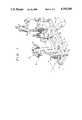
- FIG. 1is a perspective view showing the overall construction of a laser coagulation system of the present invention
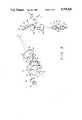
- FIG. 2is an illustrative view showing the arrangement of an optical system for a laser beam projector, slit image projector and observation equipment used in the laser coagulation system of the present invention.
- FIG. 3is a perspective view showing the arrangement of the optical system in FIG. 2.
- FIG. 1shows an embodiment of a laser coagulation system according to the present invention which includes a slider 11 mounted on a base plate 10 so as to be slidable relative to the base plate 10 in a direction X or Y by means of a manipulator 12 such as a joy stick.
- the displacement of the slider 11 relative to the base plate 10can be effected by operating the manipulator 12 in the directions X and Y.
- the slider 11supports thereon an instrument base 53 on which are mounted a slit image projector 20, a laser beam projector 21 and an observation equipment 50 as will be fully described later.
- the manipulator 12is further provided with a handle 12a, the rotation of which allows the instrument base 53 to move upwardly or downwardly in the direction Z to displace the projectors 20 and 21 together with the observation equipment 50 vertically.
- the manipulator 12can adjust the position of the instrument base 53 in the directions X and Y and in the vertical direction Z.
- the thus adjusted slider 11can be locked on the base plate 10 by means of a lock 12b.
- the base plate 10has on its front edge two poles 13 between which a chin support 14 and a forehead pad 15 are fixedly mounted.
- a patientsits down in front of the apparatus with his chin against the support 14 and his forehead against the pad 15 and directs his sight to an eye fixation lamp 16a which serves to fix the patient's eye during measurement or coagulation.
- the slit image projector 20which is turnable about the axis A (see FIG. 2) and serves to project a slit image onto the eyeball to illuminate the background and determine the portion of the eye to be measured or coagulated.
- the slit image projector 20is arranged coaxially with the laser beam projector 21 for projecting a laser beam from a source 40 such as an argon or krypton laser through an optical fiber 41 onto that portion to be coagulated in the eyeball.
- the observation equipment 50 for observing the focussed laser beam or imaged slit in the eyeballis further arranged on the front edge of the slider 11 so as to be rotated about the same axis as the turning axis A for the slit image projector 20.
- FIGS. 2 and 3show the detailed arrangement of an optical system for the laser beam projector 21, slit image projector 20 and observation equipment 50.
- the slit image projector 20is arranged in a housing 22 mounted so as to be rotated about the axis A and is provided therein with a lamp 24 which is adjustable in intensity by means of an adjusting knob 23 (see FIG. 1).
- the lamp 24emits illuminating light, which is converged by condenser lenses 25 and 25' to illuminate a slit aperture 26.
- Arranged between the condenser lens 25 and slit aperture 26are a roof-shaped prism deflection 27, an infrared ray cutting filter 28 and a detachable blue filter 29.
- the illuminated slit aperture 26is imaged, for example, onto a retina 34 of a patient's eye 33 as a slit image 34' by means of a focussing lens 30 including lenses 30a and 30b.
- a special contact lens(not shown) is attached to the patient's eye.
- a mirror assembly 35 having three-divided mirror portions 35a to 35cis mounted between the patient's eye 33 and lens 30b.
- the central mirror portion 35acan, as described later, be turned upwardly downwardly, leftwardly or rightwardly about an axis perpendicular to or within the paper surface (in FIG. 2) by means of an operating lever 12c of the manipulator 12.
- the deflection prism 27Arranged between the lens 30a and a prism 31 is a screen plate 36 which serves to interrupt the arrival of slit light to the central mirror 35a, while permitting it to reach the lower and upper mirrors 35b, 35c to the retina 34.
- the deflection prism 27has one exit surface 27a angled to deflect light in the form of one slit image component toward the lower mirror 35b and the other exit surface 27b also angles to deflect light in the form of another slit image component toward the upper mirror 35c.
- the deflection prismfunctions to form the filament image of the lamp 24 as two slit image components at two points existing on the entrance pupil of the focussing lens 30.
- the slit width and length of the slit aperture 26are adjustable by adjusting knobs 37 and 38 and the intensity of the lamp 24 by the adjusting knob 23.
- the laser beam projector 21is, on the other hand, arranged in the same housing 22 as the slit image projector 20.
- the laser beam passing through the optical fiber 41 from the laser source 40is deflected rectangularly at a prism 42 toward a variator lens 43 and a lens 44, reflected at the prism 31 and then advanced along the same optical path as the slit image projector 20 through the lens 30b, mirror 35a and contact lens to radiate a laser spot of a predetermined diameter on the retina 34 for thermal coagulation.
- the spot diameter of the laser beamcan be adjusted in the range of about 50 ⁇ m to 1 mm by turning a knob 45 and adjusting the variator lens 43.
- the instrument base 53(FIG. 1) is provided with the housing 22 for accommodating the projectors 20 and 21 and a housing 52 for accommodating the observation equipment 50, and is displaceable vertically by turning the handle 12a of the manipulator 12 as mentioned before. Further, the housings 22 and 52 are turnable relative to each other about the axis A, so that the projectors 20, 21 and the observation equipment 50 can effect upward, downward or turning movement, respectively.
- the observation equipment 50includes an optical system comprised of an objective 55, variator lenses 55 and 56', a safety filter 61, a focussing lens 57, erecting prisms 58 and 58', and eyepieces 51, 51'.
- the observation equipment 50allows the observation of the slit image and laser spot formed in the eyeball.
- the adjustment of a knob 60causes the variator lens 56 to be adjusted to provide an enlarged or reduced slit image or laser spot.
- the safety filter 61is used to interrupt the laser beam reflected back from the irradiated portion of eye or cornea and protect the eyes of an observer. For this purpose, the safety filter 61 is automatically inserted into the optical path of the observation equipment 50 immediately before the laser source 40 is activated to produce a stronger laser beam.
- the optical elements following the objective 55are provided in pairs respectively to allow binocular observation.
- the patientfirst sits down with his chin against the support 14 and his forehead against the pad 15 and directs his sight to the eye fixation lamp 16.
- the lamp 24 of the slit image projector 20is then turned on to form the slit image 34' on the retina 34 of the patient's eye 33 through the contact lens set thereon.
- the slit lighthas its central flux inhibited from reaching the central mirror 35a by means by the screen plate 36 so that the slit light is reflected only at the lower and upper mirrors 35b and 35c to form the slit image 34' on the retina 34.
- the deflection prism 27is used to deflect the slit light in the form of slit image components towards the mirrors 35b and 35c effectively.
- the intensity of the slit imagecan be adjusted by the knob 23, and the slit width and length by the adjusting knobs 37 and 38.
- the manipulator 12may be operated to displace the slider 11 and the housings 22 and 52 in the directions X, Y and Z and turn the projectors 20, 21 or observation equipment 50 about the axis A relative to each other until the slit image is formed on the desired portion for coagulation.
- the thus formed slit image 34'can be observed by the optical system of the observation equipment including the objective 55, variator lens 56, imaging lens 57, erecting prism 58 and eyepiece 51.
- the laser source 40is activated to emit a weak laser beam, which is caused to pass through the prism 42, variator lens 43, lens 44, prism 31, and lens 30b, reflected at the central mirror 35a and then focussed as a spot onto the retina 34.
- a stronger laser beamis generated from the laser source 40 by increasing the power.
- the safety filteris automatically inserted into the optical path of the observation equipment 50 to protect the eyes of the observer from the laser beam reflected from at the irradiated portion of the patients eye or retina.
- the laser spot on the retina 34can be displaced by scanning the central mirror 35a vertically or horizontally, that is, in the direction X or Y using the operating lever 12c of the manipulator 12.
- the adjustment of the knob 45allows the variator lens 43 to be displaced to adjust the spot diameter of the laser beam.
- the slit image projector and laser beam projectorcan also share a plurality of optical elements on the condition that both the projectors are arranged on the same optical axis.
Landscapes
- Health & Medical Sciences (AREA)
- Ophthalmology & Optometry (AREA)
- Heart & Thoracic Surgery (AREA)
- Vascular Medicine (AREA)
- Optics & Photonics (AREA)
- Surgery (AREA)
- Engineering & Computer Science (AREA)
- Biomedical Technology (AREA)
- Physics & Mathematics (AREA)
- Nuclear Medicine, Radiotherapy & Molecular Imaging (AREA)
- Life Sciences & Earth Sciences (AREA)
- Animal Behavior & Ethology (AREA)
- General Health & Medical Sciences (AREA)
- Public Health (AREA)
- Veterinary Medicine (AREA)
- Eye Examination Apparatus (AREA)
- Laser Surgery Devices (AREA)
- Radiation-Therapy Devices (AREA)
Abstract
Description
Claims (13)
Applications Claiming Priority (2)
| Application Number | Priority Date | Filing Date | Title |
|---|---|---|---|
| JP60-228833 | 1985-10-16 | ||
| JP60228833AJPS6290153A (en) | 1985-10-16 | 1985-10-16 | Laser photocoagulation device |
Publications (1)
| Publication Number | Publication Date |
|---|---|
| US4759360Atrue US4759360A (en) | 1988-07-26 |
Family
ID=16882570
Family Applications (1)
| Application Number | Title | Priority Date | Filing Date |
|---|---|---|---|
| US06/919,315Expired - LifetimeUS4759360A (en) | 1985-10-16 | 1986-10-14 | Laser coagulation system |
Country Status (4)
| Country | Link |
|---|---|
| US (1) | US4759360A (en) |
| EP (1) | EP0225699B1 (en) |
| JP (1) | JPS6290153A (en) |
| DE (1) | DE3677571D1 (en) |
Cited By (14)
| Publication number | Priority date | Publication date | Assignee | Title |
|---|---|---|---|---|
| USD323387S (en) | 1986-11-05 | 1992-01-21 | Messerschmitt-Bolkow-Blohm Gmbh | Laser therapy unit |
| US5400791A (en)* | 1991-10-11 | 1995-03-28 | Candela Laser Corporation | Infrared fundus video angiography system |
| US5425729A (en)* | 1985-10-18 | 1995-06-20 | Kowa Company Ltd. | Laser coagulation system |
| US5795351A (en)* | 1996-11-19 | 1998-08-18 | Visx, Incorporated | Laser refractive surgery station |
| US20090207874A1 (en)* | 2006-04-25 | 2009-08-20 | Carl Zeiss Meditec Ag | Multiwavelength laser system and method for ophtalmological applications |
| US8452372B2 (en) | 2010-10-13 | 2013-05-28 | Gholam Peyman | System for laser coagulation of the retina from a remote location |
| US8903468B2 (en) | 2010-10-13 | 2014-12-02 | Gholam Peyman | Laser coagulation of an eye structure from a remote location |
| US9037217B1 (en) | 2010-10-13 | 2015-05-19 | Gholam A. Peyman | Laser coagulation of an eye structure or a body surface from a remote location |
| USD753309S1 (en)* | 2013-09-09 | 2016-04-05 | Kowa Company, Ltd. | Slit lamp |
| US9510974B1 (en) | 2010-10-13 | 2016-12-06 | Gholam A. Peyman | Laser coagulation of an eye structure or a body surface from a remote location |
| US9931171B1 (en) | 2010-10-13 | 2018-04-03 | Gholam A. Peyman | Laser treatment of an eye structure or a body surface from a remote location |
| CN109820642A (en)* | 2019-03-01 | 2019-05-31 | 郑爱玲 | A kind of ophthalmic device for laser therapy |
| US10456209B2 (en) | 2010-10-13 | 2019-10-29 | Gholam A. Peyman | Remote laser treatment system with dynamic imaging |
| US11309081B2 (en) | 2010-10-13 | 2022-04-19 | Gholam A. Peyman | Telemedicine system with dynamic imaging |
Families Citing this family (2)
| Publication number | Priority date | Publication date | Assignee | Title |
|---|---|---|---|---|
| DE58903690D1 (en)* | 1988-04-20 | 1993-04-15 | Haag Ag Streit | DEVICE FOR EXAMINING AND TREATING THE EYE. |
| JP4762597B2 (en)* | 2005-04-28 | 2011-08-31 | 株式会社ニデック | Ophthalmic equipment |
Citations (9)
| Publication number | Priority date | Publication date | Assignee | Title |
|---|---|---|---|---|
| US2699092A (en)* | 1949-09-13 | 1955-01-11 | Zeiss Carl | Microscope with an arrangement for production of image contrasts |
| US3828788A (en)* | 1972-08-31 | 1974-08-13 | M Krasnov | Laser opthalmoscope |
| US4164222A (en)* | 1976-07-12 | 1979-08-14 | Fizichesky Institut Imeni P.N. Lebedeva Akademii Nauk SSSU of USSR | Laser ophthalmological unit |
| US4428035A (en)* | 1981-12-05 | 1984-01-24 | Carl-Zeiss-Stiftung | Electronic flashlight for ophthalmological examination instruments |
| US4477720A (en)* | 1981-12-21 | 1984-10-16 | United Technologies Corporation | Adaptive optical system having automatic feedback aperture control |
| US4499897A (en)* | 1982-03-11 | 1985-02-19 | Lasag Ag | Optical head of an installation for observation and treatment of the eye by laser radiation |
| US4520824A (en)* | 1982-09-13 | 1985-06-04 | American Hospital Supply Corporation | Instrument for ophthalmic laser surgery |
| US4561436A (en)* | 1983-10-28 | 1985-12-31 | Cooper Lasersonics, Inc. | Optical system for surgical ophthalmic laser instrument |
| US4597380A (en)* | 1982-09-30 | 1986-07-01 | Laser Industries Ltd. | Endoscopic attachment to a surgical laser |
Family Cites Families (6)
| Publication number | Priority date | Publication date | Assignee | Title |
|---|---|---|---|---|
| GB1073619A (en)* | 1964-09-23 | 1967-06-28 | Honeywell Inc | Improvements in or relating to high intensity light apparatus |
| US3703176A (en)* | 1970-05-28 | 1972-11-21 | Arthur Vassiliadis | Slit lamp photocoagulator |
| US4520816A (en)* | 1983-01-12 | 1985-06-04 | Schachar Ronald A | Method and apparatus for delivering laser energy for ophthalmic use |
| DE3306981C2 (en)* | 1983-02-28 | 1987-11-12 | Wolfram 8048 Haimhausen Weinberg | Device for the photocoagulation of biological tissue |
| FI79461C (en)* | 1983-08-22 | 1990-01-10 | Lasertek Oy | Laser system for eye surgery. |
| JPS60188150A (en)* | 1984-03-06 | 1985-09-25 | 株式会社トプコン | Ophthalmological phototherapy device |
- 1985
- 1985-10-16JPJP60228833Apatent/JPS6290153A/enactiveGranted
- 1986
- 1986-10-14USUS06/919,315patent/US4759360A/ennot_activeExpired - Lifetime
- 1986-10-14DEDE8686307947Tpatent/DE3677571D1/ennot_activeExpired - Lifetime
- 1986-10-14EPEP86307947Apatent/EP0225699B1/ennot_activeExpired
Patent Citations (9)
| Publication number | Priority date | Publication date | Assignee | Title |
|---|---|---|---|---|
| US2699092A (en)* | 1949-09-13 | 1955-01-11 | Zeiss Carl | Microscope with an arrangement for production of image contrasts |
| US3828788A (en)* | 1972-08-31 | 1974-08-13 | M Krasnov | Laser opthalmoscope |
| US4164222A (en)* | 1976-07-12 | 1979-08-14 | Fizichesky Institut Imeni P.N. Lebedeva Akademii Nauk SSSU of USSR | Laser ophthalmological unit |
| US4428035A (en)* | 1981-12-05 | 1984-01-24 | Carl-Zeiss-Stiftung | Electronic flashlight for ophthalmological examination instruments |
| US4477720A (en)* | 1981-12-21 | 1984-10-16 | United Technologies Corporation | Adaptive optical system having automatic feedback aperture control |
| US4499897A (en)* | 1982-03-11 | 1985-02-19 | Lasag Ag | Optical head of an installation for observation and treatment of the eye by laser radiation |
| US4520824A (en)* | 1982-09-13 | 1985-06-04 | American Hospital Supply Corporation | Instrument for ophthalmic laser surgery |
| US4597380A (en)* | 1982-09-30 | 1986-07-01 | Laser Industries Ltd. | Endoscopic attachment to a surgical laser |
| US4561436A (en)* | 1983-10-28 | 1985-12-31 | Cooper Lasersonics, Inc. | Optical system for surgical ophthalmic laser instrument |
Cited By (15)
| Publication number | Priority date | Publication date | Assignee | Title |
|---|---|---|---|---|
| US5425729A (en)* | 1985-10-18 | 1995-06-20 | Kowa Company Ltd. | Laser coagulation system |
| USD323387S (en) | 1986-11-05 | 1992-01-21 | Messerschmitt-Bolkow-Blohm Gmbh | Laser therapy unit |
| US5400791A (en)* | 1991-10-11 | 1995-03-28 | Candela Laser Corporation | Infrared fundus video angiography system |
| US5795351A (en)* | 1996-11-19 | 1998-08-18 | Visx, Incorporated | Laser refractive surgery station |
| US20090207874A1 (en)* | 2006-04-25 | 2009-08-20 | Carl Zeiss Meditec Ag | Multiwavelength laser system and method for ophtalmological applications |
| US8315280B2 (en)* | 2006-04-25 | 2012-11-20 | Carl Zeiss Meditec Ag | Multiwavelength laser system and method for ophtalmological applications |
| US8452372B2 (en) | 2010-10-13 | 2013-05-28 | Gholam Peyman | System for laser coagulation of the retina from a remote location |
| US8903468B2 (en) | 2010-10-13 | 2014-12-02 | Gholam Peyman | Laser coagulation of an eye structure from a remote location |
| US9037217B1 (en) | 2010-10-13 | 2015-05-19 | Gholam A. Peyman | Laser coagulation of an eye structure or a body surface from a remote location |
| US9510974B1 (en) | 2010-10-13 | 2016-12-06 | Gholam A. Peyman | Laser coagulation of an eye structure or a body surface from a remote location |
| US9931171B1 (en) | 2010-10-13 | 2018-04-03 | Gholam A. Peyman | Laser treatment of an eye structure or a body surface from a remote location |
| US10456209B2 (en) | 2010-10-13 | 2019-10-29 | Gholam A. Peyman | Remote laser treatment system with dynamic imaging |
| US11309081B2 (en) | 2010-10-13 | 2022-04-19 | Gholam A. Peyman | Telemedicine system with dynamic imaging |
| USD753309S1 (en)* | 2013-09-09 | 2016-04-05 | Kowa Company, Ltd. | Slit lamp |
| CN109820642A (en)* | 2019-03-01 | 2019-05-31 | 郑爱玲 | A kind of ophthalmic device for laser therapy |
Also Published As
| Publication number | Publication date |
|---|---|
| EP0225699A1 (en) | 1987-06-16 |
| EP0225699B1 (en) | 1991-02-20 |
| DE3677571D1 (en) | 1991-03-28 |
| JPS6290153A (en) | 1987-04-24 |
| JPH0366895B2 (en) | 1991-10-21 |
Similar Documents
| Publication | Publication Date | Title |
|---|---|---|
| US4736744A (en) | Laser coagulation system | |
| US4776335A (en) | Laser spot projector | |
| US5425729A (en) | Laser coagulation system | |
| US4759360A (en) | Laser coagulation system | |
| US5997141A (en) | System for treating the fundus of an eye | |
| JP3206923B2 (en) | Ophthalmic laser surgery device | |
| US4715704A (en) | Light trap for surgical operation microscopes | |
| US6238385B1 (en) | Laser treatment apparatus | |
| JPS5843090B2 (en) | Ophthalmological device with adjustment system | |
| JP4620471B2 (en) | Arrangement for image field improvement of ophthalmic equipment | |
| CA1267439A (en) | Slit lamp attachment | |
| US4526449A (en) | Optical system for illuminated viewing instruments | |
| WO1991001703A1 (en) | Photocoagulation apparatus | |
| JP2971479B2 (en) | Ophthalmic equipment | |
| GB2143052A (en) | Laser ophthalmic surgical system | |
| JPH06205741A (en) | Ophthalmic equipment | |
| US6830335B2 (en) | Ophthalmoscope laser attachment | |
| JPH036813B2 (en) | ||
| JP3264990B2 (en) | Corneal endothelial cell imaging device | |
| JP2585646B2 (en) | Laser therapy equipment | |
| JPH07194645A (en) | Laser therapeutic instrument | |
| JPS6322823B2 (en) | ||
| JPH0423524Y2 (en) | ||
| JP3953657B2 (en) | Fundus camera | |
| JPS63161949A (en) | Laser irradiation apparatus for remedy |
Legal Events
| Date | Code | Title | Description |
|---|---|---|---|
| AS | Assignment | Owner name:KOWA COMPANY LTD., 6-29, NISHIKI 3-CHOME, NAKA-KU, Free format text:ASSIGNMENT OF ASSIGNORS INTEREST.;ASSIGNORS:NAKANISHI, TAKAJI;HENNINGS, DAVID R.;NIINO, MASAO;REEL/FRAME:004817/0784 Effective date:19861027 Owner name:COHERENT INCORPORATED, 3210 PORTER DRIVE, PALO ALT Free format text:ASSIGNMENT OF ASSIGNORS INTEREST.;ASSIGNORS:NAKANISHI, TAKAJI;HENNINGS, DAVID R.;NIINO, MASAO;REEL/FRAME:004817/0784 Effective date:19861027 | |
| STCF | Information on status: patent grant | Free format text:PATENTED CASE | |
| FEPP | Fee payment procedure | Free format text:PAYOR NUMBER ASSIGNED (ORIGINAL EVENT CODE: ASPN); ENTITY STATUS OF PATENT OWNER: LARGE ENTITY | |
| FPAY | Fee payment | Year of fee payment:4 | |
| FPAY | Fee payment | Year of fee payment:8 | |
| FPAY | Fee payment | Year of fee payment:12 | |
| AS | Assignment | Owner name:BANK HAPOALIM B.M., ISRAEL Free format text:SECURITY INTEREST;ASSIGNOR:ESC MEDICAL SYSTEMS INC.;REEL/FRAME:011846/0061 Effective date:20010413 Owner name:ESC MEDICAL SYSTEMS, INC., MASSACHUSETTS Free format text:ASSIGNMENT OF ASSIGNORS INTEREST;ASSIGNOR:COHERENT, INC.;REEL/FRAME:011846/0115 Effective date:20010427 | |
| AS | Assignment | Owner name:LUMENIS INC., MASSACHUSETTS Free format text:CHANGE OF NAME;ASSIGNOR:ESC MEDICAL SYSTEMS INC.;REEL/FRAME:011911/0540 Effective date:20010425 |