US4759051A - Communications system - Google Patents
Communications systemDownload PDFInfo
- Publication number
- US4759051A US4759051AUS07/025,970US2597087AUS4759051AUS 4759051 AUS4759051 AUS 4759051AUS 2597087 AUS2597087 AUS 2597087AUS 4759051 AUS4759051 AUS 4759051A
- Authority
- US
- United States
- Prior art keywords
- transponder
- cell set
- radio
- zone
- radio zone
- Prior art date
- Legal status (The legal status is an assumption and is not a legal conclusion. Google has not performed a legal analysis and makes no representation as to the accuracy of the status listed.)
- Expired - Lifetime
Links
Images


Classifications
- H—ELECTRICITY
- H04—ELECTRIC COMMUNICATION TECHNIQUE
- H04W—WIRELESS COMMUNICATION NETWORKS
- H04W16/00—Network planning, e.g. coverage or traffic planning tools; Network deployment, e.g. resource partitioning or cells structures
- H04W16/24—Cell structures
- H04W16/26—Cell enhancers or enhancement, e.g. for tunnels, building shadow
- H—ELECTRICITY
- H04—ELECTRIC COMMUNICATION TECHNIQUE
- H04B—TRANSMISSION
- H04B7/00—Radio transmission systems, i.e. using radiation field
- H04B7/24—Radio transmission systems, i.e. using radiation field for communication between two or more posts
- H04B7/26—Radio transmission systems, i.e. using radiation field for communication between two or more posts at least one of which is mobile
- H04B7/2603—Arrangements for wireless physical layer control
- H04B7/2606—Arrangements for base station coverage control, e.g. by using relays in tunnels
- H—ELECTRICITY
- H04—ELECTRIC COMMUNICATION TECHNIQUE
- H04B—TRANSMISSION
- H04B7/00—Radio transmission systems, i.e. using radiation field
- H04B7/24—Radio transmission systems, i.e. using radiation field for communication between two or more posts
- H04B7/26—Radio transmission systems, i.e. using radiation field for communication between two or more posts at least one of which is mobile
- H04B7/2621—Radio transmission systems, i.e. using radiation field for communication between two or more posts at least one of which is mobile using frequency division multiple access [FDMA]
Definitions
- This inventionrelates to communications systems, and more specifically to an improved cellular radiotelephone communications system for voice communication between radiotelephone units and other telephones or radiotelephone units.
- each zonecontains a base station.
- the base stationsare all connected to a mobile telephone central control and switching office which exercises supervisory control over the system.
- Each base stationoperates in several assigned voice channels selected so that they do not interfere with channels of nearby zones. Because of the restricted power and range of the base stations and of the portable units, each set of zone frequencies can be reused in a non-adjacent zone. However, because adjacent zones use different sets of frequencies, the cellular system operates by a "hand-off" process which takes place as a portable unit moves from one zone to another.
- the supervisory systemautomatically follows each portable unit by monitoring its transmitted signal strength, as received by nearby base stations. When a portable unit enters a new zone, the supervisory system automatically causes the portable unit to switch to a new uplink and downlink channel pair available in the zone being entered.
- Radio zones in cellular mobile communications systems currently in useare typically one to twenty miles across. Reducing the sizes of these zones, and thus reducing the power requirements of the transmitter of the portable unit, would not solve the problem of miniaturization, because the supervisory system would need to handle hand-offs too frequently. At a zone size of one mile across, for example, the frequency of hand-offs would put a strain on the computer of the supervisory system.
- Another problem in conventional cellular radiotelephone systemsis that occasionally the assigned channels in a given zone may all be in use. When this occurs, a user may not be able to obtain access to the system when he desires to do so. This condition may occur occasionally, even though elaborate measures are taken to predict the usage of each of the zones in a cellular system.
- the principal object of this inventionis to overcome the foregoing problems, and specifically to provide a practical portable radiotelephone communications system in which the portable units are small and light in weight so that they can be more conveniently carried on the person, for example as pocket-sized units. It is also an object of the invention to provide improved user access in a radiotelephone communications system. Another object of the invention is to enable networks of fixed telephones to be set up rapidly and inexpensively by reducing or eliminating the need for overhead or underground cables. Still another object of the invention is to make it possible to change positions of telephones, in offices or homes, for example, without rewiring, and to make it possible for a telephone subscriber to move from one location to another without the need for installing a new telephone line or changing the subscriber's telephone number. A further object is to reduce the cost to the telephone subscriber by enabling a number of subscribers to share a single telephone channel.
- the communications system in accordance with the inventionis similar to a conventional cellular system in that it comprises a telephone control and switching office, at least one local telephone office connected to the switching office and including means to connect the switching office to selected fixed telephones, and a plurality of cell sets, each connected to the switching office through a two-way communication link.
- the system of the inventiondiffers from prior cellular systems in that each cell set has associated with it a plurality of relay transponders. Each cell set and its associated transponders are located in a separate geographically defined radio zone. Within each radio zone, a two-way radio communication link is provided between each transponder and the cell set.
- Each transponderincludes means for relaying uplink and downlink radio signals between its associated cell set and radiotelephone units in the vicinity of the transponder.
- Each cell setincludes means for relaying two-way communications signals between its associated transponders and the switching office, and also includes means for communicating directly with radiotelephone units in the immediate vicinity of the cell set and for relaying two-way communications signals between the last-mentioned radiotelephone units and the switching office.
- a portable unitAs a portable unit moves about a radio zone, it can communicate directly with the radio zone's cell set, if it is in the vicinity of the cell set. Otherwise, it communicates with the cell set through one or more relay transponders.
- the use of relay transpondersreduces the power requirements of the portable units by reducing the "talk back" distance. Therefore, they can use small, comparatively inexpensive batteries, and can be made so small and light in weight that they can be more easily carried about on the person.
- Hand-offdoes take place when a portable unit moves from one radio zone to another.
- the hand-off system of the inventionis unique in that each portable unit monitors the average strength of the downlink voice channel in use, and transmits a hand-off request signal if the strength of the received downlink signal falls below a preestablished level.
- the control officedetermines the radio zone being entered by the portable unit by comparing the strength of the hand-off request signal at several transponders in the vicinity of the portable unit. Otherwise hand-off is carried out by the same procedure currently in use in conventional cellular telephone systems.
- channel reassignmentis either supplemented or replaced by a system in which the sizes and shapes of the radio zones are changed as conditions change. For example, during daytime hours, the radio zones in a business district can be reduced in size so that each zone is likely to contain fewer portable units, and the ratio of available channels to the number of users in each such zone is increased.
- the channels assigned to the reduced radio zoneare less likely to be all in use at any given time.
- the business area radio zonescan be enlarged to include portions of outlying areas, and at the same time, the radio zones in the outlying areas can be correspondingly reduced in size.
- Changing the size and shape of radio zonesis accomplished in a simple manner by taking a transponder or a group of transponders originally assigned to one cell set, and assigning them to a different cell set, the changes being determined on the basis of a statistical average.
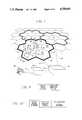
- FIG. 1is a schematic diagram illustrating the radio zone arrangement in a very simple embodiment of the invention
- FIG. 2is a schematic diagram of a more elaborate embodiment, showing a first arrangement of radio zones in a geographical area
- FIG. 3is a schematic diagram of the same geographical area as in FIG. 2, but showing an alternative arrangement of radio zones;
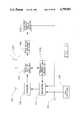
- FIG. 4is a schematic diagram showing details of the communication paths of FIG. 2;
- FIG. 5is a schematic diagram showing details of the communication path of FIG. 3;
- FIG. 6is a schematic diagram of a typical cell set in accordance with the invention.
- FIG. 7is a schematic diagram of a typical relay transponder
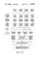
- FIG. 8is a schematic diagram of a set of radio zones, showing portable units, each of which is moving from one radio zone to another;
- FIG. 9is a block diagram showing the format of a hand-off request signal
- FIG. 10is a block diagram showing the format of a signal generated in a transponder in response to a hand-off request
- FIG. 11is a schematic diagram of a portable unit.
- FIG. 12is a flow chart depicting the hand-off sequence in accordance with the invention.
- a geographical areais divided into radio zones.
- each of these radio zonescan be thought of as further subdivided into equilateral, equiangular hexagons of uniform size.
- Uniform hexagon sizehas two advantages. First, uniformity makes it unnecessary for the portable units to be capable of switching between different power levels, as is the case with conventional mobile cellular telephones. Secondly, uniformity of hexagon size means that the transponders can be of standard design, thereby reducing overall system cost.
- a radio zonecan be of any desired shape, and may consist of any desired number of subdivisions.
- a given telephone systemcan comprise radio zones of different sizes and shapes.
- FIG. 1shows a typical radio zone 18, comprising seven hexagonal cells 20, 22, 24, 26, 28, 30 and 32.
- Hexagonal cell 32is centrally located within the zone, and six hexagons 20-30 surround the central hexagon.
- Each of the surrounding hexagons 20-30contains a centrally located transponder for radio communication with portable units located in its hexagon.
- Central hexagon 32also contains a cell set 36.
- Transponder 34is typical. It has an omnidirectional antenna 38 for communication with portable units within hexagon 20. Instead of an omnidirectional antenna, several directional antennas, each covering a different part of a cell may be used. Alternatively, if the transponder is not centered in a cell, its antenna may have a directional characteristic enabling it to cover the entire cell.
- Directional antenna 44 of transponder 34communicates with directional antenna 46 of cell set 36 over path 48.
- Directional antenna 46is one of six directional antennas associated with the cell set. Each of these directional antennas is arranged to provide two-way communication between the cell set and a transponder in one of hexagons 20-30.
- Cell set 36also has an omnidirectional antenna 50 for communication with portable units located within central hexagon 32.
- Cell set 36is in communication with portable telephone switching and control office 52 over path 51, which can be a microwave link, a wired link, a fiberoptic link, or any other form of two-way communication link.
- Office 52is similarly connected to the cell sets of other radio zones, e.g. over path 53.
- Office 52is connected to local telephone office 56 over lines 54, and the local telephone office is connected to fixed telephones such as telephone 58, which is connected to local office 56 through line 60.
- Portable unit 40can be placed in communication with fixed telephone 58 by relaying signals through transponder 34, cell set 36, switching office 52 and local telephone office 56.
- the size and weight of the batteries and transmitter componentswere the main factors contributing to the size and weight of the portable units.
- the portable unitscould not be carried conveniently on the person.
- the division of radio zones into small hexagons, each with a relay transponderallows the portable units to use much smaller batteries and less powerful, and therefore smaller, transmitter components.
- a typical hexagonal subdivision of a radio zonehas a maximum dimension of approximately one mile. Consequently the maximum length of a radio link between a portable unit and a centrally located transponder within a hexagon is approximately one-half mile. Communication over this short distance can be carried out with low power. Consequently, the batteries and transmitter components of the portable units, can be small in size and light in weight.
- the portable unitcan be easily carried about by an individual, and kept in the individual's pocket when not in use.
- a pair of voice channelsconsisting of an uplink channel and a downlink channel, is established. These channels remain in effect as the portable unit moves about from hexagon to hexagon within the radio zone during a given telephone call.
- hand-offtakes place in a manner which will be described.
- One feature of the inventionis its ability to accommodate changes in the geographic distribution of portable telephone traffic by radio zone rearrangement. These changes may occur, for example between daytime and evening, in a system which encompasses both a business district and a residential area.
- the business districtitself can be divided into relatively small radio zones, each of which is then capable of handling all of the portable units within it.
- the radio zones in the residential areascan be made large, because concentration of portable telephone traffic in the residential area is comparatively low.
- the concentration patternshifts, and the radio zones can be rearranged so that the radio zones in the residential areas are reduced in size. It is even possible to set up a radio zone which encompasses both business and residential areas.
- FIG. 2illustrates a typical arrangement of radio zones during evening hours.
- Each zoneconsists of fourteen hexagons, thirteen of which contain transponders, and the fourteenth of which contains a cell set.
- radio zonesare indicated at 62, 64, 66, 68, 70 and 72.
- the business district in FIG. 2is indicated by cross-hatching. Part of each of zones 64, 66 and 70 is in the business district.
- the cell set C 1 for zone 64is located in the business district.
- Portable unitsare shown at 74, 76, 78 and 80 in the residential part of zone 64, and portable units 82 and 84 are indicated in the business district within zone 64.
- a communication pathis shown from transponder T 1 through transponders T 2 , T 3 and T 4 to cell set C 1 .
- Signals to and from portable unit 74are relayed through transponders T 1 , T 2 , T 3 and T 4 to cell set C 1 .
- Signals to and from portable units 76 and 78are relayed through transponders T 2 , T 3 and T 4 to cell set C 1 .
- Signals to and from portable unit 80are relayed through transponders T 3 and T 4 .
- Signals to and from portable unit 82which is in the same hexagon as cell set C 1 , are received directly by the cell set.
- a second communication pathis shown between transponder T 5 and cell set C 1 .
- Signals to and from portable unit 84are relayed to cell set C 1 through transponder T 5 .
- radio zone 72the cell set is indicated at C 2 .
- a portable unit 86communicates with cell set C 2 through transponder T 6 .
- the radio zonesare rearranged, as shown in FIG. 3.
- the business districtis divided into three radio zones 88, 90 and 92, each comprising seven hexagons.
- the outlying residential areasare divided into three radio zones, 94, 96 and 98, each comprising twenty-one hexagons.
- signals to and from portable unit 74are relayed to cell set C 2 , rather than to cell set C 1 .
- Relaytakes place through transponders T 1 , T 2 , T 3 and T 6 .
- the business districtcan handle more portable telephone traffic, because there is no competition in those zones from portable units outside the business district.
- more portable telephone trafficcan be handled in the outlying residential areas. It is possible to rearrange the sizes and shapes of radio zones by activating or deactivating certain cell sets and simultaneously shifting transponders into communication with active cell sets as required. However, usually, all cell sets will remain active at all times as in the system depicted in FIGS. 2 and 3, where for each contraction of one radio zone, there is a corresponding enlargement of one or more other zones.
- Cell sets C 1 and C 2are connected to portable telephone switching and control office 100, which not only performs signal switching, but also remotely controls operations of the cell sets and transponders.
- the switching officeis connected to a local office 102. Numerous telephones, including telephone 104 are connected to local office 102.
- Transponder T 1has an omnidirectional antenna 106, which receives and transmits signals from and to portable units, such as unit 74, within the hexagon containing transponder T 1 .
- Transponder T 1also has a directional antenna 108, which is aligned with directional antenna 110 of transponder T 2 . Signals to and from portable unit 74 are relayed through the communication path established by directional antennas 108 and 110.
- Directional antenna 110is one of six directional antennas connected to transponder T 2 .
- Transponder T 2communicates with each of its six adjacent transponders through these directional antennas.
- transponder T 2serves as a central unit for relaying singals between transponder T 3 on the one hand and transponders T 1 , T 7 , T 8 , T 9 and T 10 on the other.
- the four directional antennas on transponder T 2 other than antennas 110 and 112are coupled to the transponder so that, operationally, they are duplicates of antenna 110.
- Alternative arrangementsare possible. For example, in FIG.
- transponder T 3could have directional antennas communicating directly with transponders T 7 and T 8
- transponder T 2could have directional antennas communicating with transponders T 10 , T 1 and T 9 , but not with transponders T 7 and T 8 .
- Each portable unitis capable of emitting uplink control signals at any of several frequencies f c1 ', f c2 ', etc.
- Frequencies f c1 ' and f c2 ', etcwill be referred to collectively as frequencies f cx '.
- frequencies f cx 'For each uplink control frequency, there is a corresponding downlink control frequency.
- frequencies f cxthere is a set of downlink control frequencies f c1 , f c2 , etc. collectively referred to as frequencies f cx . Therefore, f cx and f cx ' represent groups of control frequencies (also referred to as "control channels").
- each radio zoneis assigned a unique control channel, or a unique group of control channels, from the twenty-one control channels available in each of the "A" and "B" bands designated by the Federal Communications Commission.
- the portable unitscans the available downlink control channels, and selects the control channel having the strongest signal.
- the portable unitidentifies itself by sending a coded signal on the corresponding uplink control channel.
- the control and switching officeselects a vacant downlink voice channel from those channels assigned to the radio zone corresponding to that uplink control channel.
- the vacant downlink voice channelis identified over the downlink control channel, and the portable unit receiver then locks onto the vacant voice channel thus identified.
- the portable unitthen acknowledges receipt of the downlink voice channel by transmitting a coded message on the corresponding uplink voice channel. Lockout automatically occurs when an uplink and downlink voice channel pair is established, so that other portable units within the radio zone cannot use these channels.
- This procedure for establishing a connectionis essentially identical to the procedure carried out in conventional cellular telephone systems.
- the portable unitis capable of transmitting voice-modulated signals in any of a number of uplink voice channels f 1 '-f n ', and of receiving voice-modulated signals in any of downlink voice channels f 1 -f n .
- Groups of voice channelsare assigned to each radio zone.
- the uplink voice channels assigned to the radio zone having cell set C 1are designated f 1 ' through f 6 ' and the downlink voice channels are designated f 1 and through f 6 .
- the number of voice channels assigned to a radio zonecan, of course, be more than six.
- a voice channel pairis assigned to each portable unit immediately following the beginning of a telephone call to or from that unit after contact has been established over a control channel.
- each downlink voice channel f xthere is a corresponding uplink voice channel f x '.
- each downlink channelis 45 Mhz. above the frequency of its corresponding uplink channel.
- Channelsare established at 30 Khz. intervals. Available voice frequencies are subdivided into groups, and adjacent radio zones are assigned different groups of channels to avoid interference. Non-adjacent radio zones can use the same voice channels.
- Cell set C 1sends downlink signals including control channel f cx and voice channels f 1 -f n , where f n is the downlink channel corresponding to the highest numbered uplink channel received by the cell set.
- f nis the downlink channel corresponding to the highest numbered uplink channel received by the cell set.
- Voice channel and control signals to and from portable units 76 and 78are relayed through transponder T 2 , and through directional antenna 112 of transponder T 2 and directional antenna 114 of transponder T 3 .
- Signals to and from portable unit 74are also relayed through the path between directional antennas 112 and 114.
- transponder T 2the uplink signals from portable units 76 and 78 are combined with the uplink signal from portable unit 74, and relayed from transponder T 2 to transponder T 3 .
- transponder T 3can be connected alternatively to directional antennas 116 and 118 by antenna switch 120, which is operable by a control signal from office 100. Switch 120, and other switches (not shown) in other parts of the system effect rearrangement of the radio zones.
- Transponder T 4relays signals between transponder T 3 and cell set C 1 through directional antennas 121 and 122.
- Cell set C 1has six directional antennas. These include antenna 122, and antenna 124, which provides a communication link with transponder T 5 . Cell set C 1 also has an omnidirectional antenna 126, which transmits and receives signals to and from portable units near the cell set such as portable unit 82.
- FIG. 4also shows cell set C 2 , which is in communication with portable unit 86 through transponder T 6 .
- Cell set C 2is in a separate radio zone adjacent to the zone containing cell set C 1 . Consequently the voice frequency channels used in the zone of cell set C 2 should not duplicate those used in the zone of cell set C 1 .
- Portable unit 86is assigned an uplink voice channel f 7 ' and a downlink voice channel f 7 .
- Channels f 7 and f 7 'are in a group of voice channels assigned to the radio zone of cell set C 2 , which is different from the group assigned to cell set C 1 .
- FIG. 5shows the details of the communication path depicted in FIG. 3, in which the radio zone configuration is different from that shown in FIG. 2.
- Portable unit 74is in communication with cell set C 2 through transponders T 1 , T 2 , T 3 and T 6 .
- Antenna switch 120connects transponder T 3 to directional antenna 118, which is aimed toward directional antenna 128 of transponder T 6 .
- the other directional antenna 130 of transponder T 6is aimed toward directional antenna 132 of cell set C 2 .
- radio zone rearrangementcan be used by itself to improve operating efficiency, or both channel reassignment and radio zone rearrangement can be used.
- the switching and control officeassigns to each of the current users a new uplink and downlink voice channel pair.
- a radio zone rearrangementcan take place, therefore, with only a momentary interruption in ongoing telephone calls.
- the objective of radio zone rearrangementis to set up a radio zone on a statistical basis so that the number of portable units likely to be in use in a radio zone at a particular time will not exceed, or at least not greatly exceed the channel handling capability of the cell set for that zone.
- the zonesmay be rearranged so that a zone of reduced size encompasses that particular area.
- areas of reduced portable telephone trafficcan be encompassed by expanded zones.
- An advantage of changing the shape and size of a radio zone to accommodate changing conditions of usageis that the zones not involved in the change are not affected.
- the channel assignments in many other zonesare often affected.
- FIG. 6illustrates a typical cell set, such as C 1 .
- the cell set of FIG. 6has six directional antennas 122, 134, 124, 136, 138 and 140, and also has one omnidirectional antenna 126.
- the number of directional antennas on the cell setcan be as many as six, and as few as one. If the hexagon containing the cell set is completely surrounded by other hexagons in the same radio zone, the number of directional antennas will normally be six. However, in the case of a radio zone comprising a line of hexagons with the cell set in the hexagon at one end of the line, the cell set would normally only have one directional antenna.
- the directional antennas and the omnidirectional antennaare all connected through conventional duplexers to a receiver 142 and a transmitter 144.
- the duplexersenable a single antenna to handle transmitted and received signals simultaneously. These signals will normally be at least 25 Mhz. apart.
- the receiver and transmitterare connected to control logic 146, which is in turn connected through line 148 to a switching and control office, as shown in FIGS. 4 and 5.
- the control logic of the cell setmay include a control microprocessor and a status memory to retain information including the number of users in the radio zone, identification of the available voice frequencies not in use in the zone, and utilization volume.
- the control logic of the cell setmay also operate to assign a specific uplink and downlink voice channel pair to each user within the radio zone. Alternatively, this assignment can be carried out under the direction of the switching and control office.
- the control logicalso controls calling and dialing logic, processes messages delivered through it from receiver 142, and links users in the radio zone with the telephone network. Likewise, it controls transmitter 144 to send messages from the fixed telephone network to the portable units.
- FIG. 7shows details of transponder T 3 , with its antenna switch 120 in the position shown in FIG. 4.
- Transponder T 3is typical of the transponder of the system. Its directional antenna 114 is connected through duplexer 150 to a receiver/amplifier 152. Frequencies f cx ' and f 1 '-f 3 ' are transmitted through the duplexer and receiver/amplifier to transmitter 154, where they are combined with signals from OR-gate 123, including a control signal at frequency f cx ' and a voice signal at frequency f 4 '. The output of transmitter 154 is delivered to duplexer 157, which is connected through switch 120 to antenna 116.
- the signals entering transmitter 154 at frequencies f cx ' and f 4 'are uplink signals from a portable unit 80, received by omnidirectional antenna 158 and delivered through duplexer 160 and receiver 156.
- the output of transmitter 164is delivered through duplexer 150 to directional antenna 114, and the output of transmitter 166 is delivered through duplexer 160 to omnidirectional antenna 158.
- uplink frequencies received by directional antenna 114 and by omnidirectional antenna 158are combined and are all transmitted (toward a cell set) through directional antenna 116 (or through antenna 118, if selected by switch 120). Although uplink signals are combined, downlink signals are not split. Every downlink frequency received by directional antenna 116 is retransmitted through directional antenna 114 and also through omnidirectional antenna 158.
- the receiver/amplifiers, and the duplexer and transmitters as well, in the transponderare preferably capable of handling both the A and B bands, designated for cellular service by the rules of the Federal Communications Commission, 47 CFR ⁇ 22.902.
- elements handling uplink signalsshould have a bandwidth encompassing 825.030 Mhz.-844.980 Mhz.
- Elements of the transponder which handle downlink signalsshould have a bandwidth encompassing 870.030 Mhz.-889.980 Mhz.
- An antenna switching command from a cell set(C 1 or C 2 , depending on which of antennas 116 and 118 is connected to the transponder) is delivered through antenna switch 120, duplexer 157, and receiver/amplifier 162 to an antenna switch command (ASC) buffer register 168.
- ASCantenna switch command
- the output of ASC buffer register 168is decoded by decoder 170, which controls operation of antenna switch 120, through power amplifier 172, which delivers a pulse causing the antenna switch to shift from antenna 116 to antenna 118 or vice versa.
- the remainder of the elements in FIG. 7pertain to the processing of hand-off information.
- the output of receiver 156can be connected directly to an input of transmitter 154.
- the central officemay need an identification from the transponder in order to determine which radio zone the portable unit is entering.
- a hand-off request detector 127 and a transponder I.D. generator 119are provided.
- the output of receiver 156is connected to transmitter 154 through hand-off request signal detector 127 and OR-gate 123.
- An output of detector 127is merged with an output of transponder I.D. generator 119 by means of adder 121, the output of which goes to transmitter 154 through OR-gate 123.
- a portable unitcan move about from hexagon to hexagon within a given radio zone without the uplink or downlink frequencies being changed. In other words, there is no hand-off as the portable unit moves from one hexagon to another in the same radio zone. Rather, the closest transponder takes over gradually as the portable unit moves. All portable units within a given radio zone operate in different voice channels. As stated previously, f cx represents a number of control frequencies, as does f cx '. The control signals require only short time intervals. Therefore, each control channel can accommodate many users.
- FIG. 8shows radio zones 88, 90 and 92, with four portable units 1-4, each moving from one radio zone to an adjacent zone.
- the modulation level of the received voice signalis sampled, and an average value established continually. This average value is compared with a predetermined threshold level. If the average value of the voice signal modulation falls below the threshold level, a hand-off request signal is transmitted by the portable unit in short bursts over the voice channel.
- the signalis in the format shown in FIG. 9. It contains the request and identifies the portable unit making the request.
- the signalis transmitted via several transponders and by two or more cell sets to the central control and switching office. The central office determines which radio zone the portable unit is in and which radio zone the unit is going to by comparing the strengths of the hand-off request signals.
- the transponder I.D.is provided by generator 119, the output of which is added to the hand-off request and merged with non-hand-off signals in OR-gate 123, as shown in FIG. 7.
- the format of the output of adder 121is seen in FIG. 10.
- the central officeselects an available voice frequency from those that can be used in the new radio zone, alerts the new cell set that a hand-off is about to occur and identifies the portable unit and the frequency to be used.
- the central officevia the cell set and the transponder, sends a message to the portable unit to switch to the new frequency and radio zone.
- the portable unitacknowledges receipt of the message with a brief burst of signal over the original voice frequency, turns off its receiver and then retunes to its new channel.
- the central officerecognizing the burst of signal, turns off the old frequency and switches the trunk line to the new frequency.
- the portable unitthen starts to transmit over the corresponding uplink frequency and the central office knows that a successful hand-off has been completed.
- FIG. 12also shows that when unit 1 moves from one hexagon to another within a radio zone, no hand-off occurs.
- the portable unitcomprises a transmitter 174, to which are connected a microphone 176 and a "touch tone" keyboard 178.
- the portable unitalso comprises a receiver 180, which drives a speaker 182. Both the transmitter and receiver are connected to antenna 184 through duplexer 186.
- the modulation level of the received signalis sampled by voice signal strength detector 188, which, if the average modulation level falls below a predetermined threshold, indicates that the portable unit is moving from one radio zone to another, and triggers hand-off request signal generator 200, which causes transmitter 174 to send out a hand-off request.
- the receiveralso includes an "I.D. identifier", which identifies the telephone number of the portable unit.
- the frequency scanning and seizing unit 238locks receiver 180 onto the available downlink frequency.
- the scanning and seizing unitautomatically scans frequencies over a short range on both sides of the assigned downlink frequency, and locks onto the frequency of the downlink carrier signal for optimum reception.
- unit 238causes transmitter 174 to lock onto a corresponding uplink frequency.
- the system of the inventioncan be readily adapted to existing cellular telephone systems by providing relay transponders at selected locations in each radio zone.
- the hand-off procedureis essentially the same as that used in conventional cellular systems, except that the need for hand-off is determined by monitoring downlink signal strengths rather than by monitoring uplink signal strengths.
- two-way relay transpondersallows the portable units to be smaller and lighter in weight than conventional portable units.
- the use of two-way relay transpondershas the additional advantage that it permits operating efficiency to be achieved easily by rearrangement of radio zones to accommodate changing conditions of use.
- each radio zonehas one or more base stations, each with a central transmitting antenna covering the entire zone and several receiver sites at separate locations in the zone in order to reduce talk back distance for the portable units.
- an original radio zonemight initially have two base stations, each surrounded by a set of receiver sites.
- One of the base stations and its surrounding receiver sitescould be dissociated from the other base station in the same zone and associated with another base station to form a new zone having two base stations and to reduce the original radio zone to one having a single base station, and therefore a higher radio of available channels to the number of users within the zone.
- a cell setcan be located adjacent to the boundary of a radio zone.
- Changing the shape of radio zones by switching of directional antennas under the control of the switching officecan be carried out automatically in response to changing demand conditions sensed by the switching office computer.
- the inventionis primarily useful for portable radiotelephone communications, it can also be used advantageously in fixed telephone communications networks. These networks can be set up rapidly and inexpensively as the invention eliminates the need for overhead or underground wires and cables. The invention also makes it possible to relocate telephones in offices and homes more easily, by eliminating the need for rewiring. It also makes it possible for a telephone subscriber to move from one location to another without involving the telephone company.
Landscapes
- Engineering & Computer Science (AREA)
- Computer Networks & Wireless Communication (AREA)
- Signal Processing (AREA)
- Mobile Radio Communication Systems (AREA)
Abstract
Description
Claims (7)
Priority Applications (3)
| Application Number | Priority Date | Filing Date | Title |
|---|---|---|---|
| US07/025,970US4759051A (en) | 1987-03-16 | 1987-03-16 | Communications system |
| GB8716896AGB2203018B (en) | 1987-03-16 | 1987-07-17 | Communications system |
| HK1023/90AHK102390A (en) | 1987-03-16 | 1990-12-06 | Communications system |
Applications Claiming Priority (1)
| Application Number | Priority Date | Filing Date | Title |
|---|---|---|---|
| US07/025,970US4759051A (en) | 1987-03-16 | 1987-03-16 | Communications system |
Publications (1)
| Publication Number | Publication Date |
|---|---|
| US4759051Atrue US4759051A (en) | 1988-07-19 |
Family
ID=21829094
Family Applications (1)
| Application Number | Title | Priority Date | Filing Date |
|---|---|---|---|
| US07/025,970Expired - LifetimeUS4759051A (en) | 1987-03-16 | 1987-03-16 | Communications system |
Country Status (3)
| Country | Link |
|---|---|
| US (1) | US4759051A (en) |
| GB (1) | GB2203018B (en) |
| HK (1) | HK102390A (en) |
Cited By (98)
| Publication number | Priority date | Publication date | Assignee | Title |
|---|---|---|---|---|
| US4843633A (en)* | 1986-02-18 | 1989-06-27 | Motorola, Inc. | Interface method and apparatus for a cellular system site controller |
| EP0347396A1 (en)* | 1988-06-14 | 1989-12-20 | Telefonaktiebolaget L M Ericsson | Handover method for mobile radio system |
| WO1990003071A1 (en)* | 1988-09-05 | 1990-03-22 | Aahl Karl Axel | Method and system in a wide area radio communication network |
| US4926421A (en)* | 1987-10-23 | 1990-05-15 | Mitsubishi Denki Kabushiki Kaisha | Mobile radio telephone system |
| US4972456A (en)* | 1989-02-10 | 1990-11-20 | Gte Mobilnet Incorporated | Rural radiotelephone system |
| US4977612A (en)* | 1989-10-10 | 1990-12-11 | Motorola, Inc. | Channel selection in a multi-frequency radio data communication system |
| WO1991007019A1 (en)* | 1989-11-07 | 1991-05-16 | Pactel Corporation | Zoned microcell with sector scanning for cellular telephone systems |
| WO1991007043A1 (en)* | 1989-11-07 | 1991-05-16 | Pactel Corporation | Improved microcell system for cellular telephone systems |
| EP0435283A1 (en)* | 1989-12-28 | 1991-07-03 | Nec Corporation | Antenna arrangement system capable of reducing co-channel interference |
| JPH03166832A (en)* | 1989-09-14 | 1991-07-18 | Pcn One Ltd | Radio communication system |
| JPH03166831A (en)* | 1989-09-14 | 1991-07-18 | Pcn One Ltd | mobile radio communication equipment |
| US5067171A (en)* | 1987-03-31 | 1991-11-19 | Mitsubishi Denki Kabushiki Kaisha | Method and apparatus for hand-off of call in progress |
| US5067147A (en)* | 1989-11-07 | 1991-11-19 | Pactel Corporation | Microcell system for cellular telephone system |
| US5088108A (en)* | 1988-02-29 | 1992-02-11 | Telefonaktiebolaget L M Ericsson | Cellular digital mobile radio system and method of transmitting information in a digital cellular mobile radio system |
| US5168575A (en)* | 1990-09-28 | 1992-12-01 | Motorola, Inc. | Demand driven wide-area radio system resource assignment method and apparatus |
| US5193109A (en)* | 1989-02-06 | 1993-03-09 | Pactel Corporation | Zoned microcell with sector scanning for cellular telephone system |
| US5212830A (en)* | 1991-05-31 | 1993-05-18 | International Mobile Machines Corporation | Radio frequency communications system |
| US5243641A (en)* | 1990-08-01 | 1993-09-07 | At&T Bell Laboratories | Extended range cordless telephone system |
| EP0563896A1 (en)* | 1992-03-31 | 1993-10-06 | Casio Computer Co., Ltd. | Method and apparatus for calling a handset unit in radio telephone system |
| US5274841A (en)* | 1990-10-29 | 1993-12-28 | International Business Machines Corporation | Methods for polling mobile users in a multiple cell wireless network |
| US5309503A (en)* | 1991-12-06 | 1994-05-03 | Motorola, Inc. | Dynamic channel assignment in a communication system |
| US5313461A (en)* | 1989-10-19 | 1994-05-17 | Inventahl Ab | Method and device in a digital communication network |
| US5327577A (en)* | 1988-06-14 | 1994-07-05 | Telefonaktiebolaget L M Ericsson | Handover method for mobile radio system |
| US5353333A (en)* | 1992-12-30 | 1994-10-04 | At&T Bell Laboratories | Small wireless telecommunications system |
| EP0596521A3 (en)* | 1992-11-06 | 1994-11-17 | Texas Instruments Deutschland | Multi-interrogator, datacom, and transponder arrangement. |
| US5371780A (en)* | 1990-10-01 | 1994-12-06 | At&T Corp. | Communications resource assignment in a wireless telecommunications system |
| US5384826A (en)* | 1990-10-01 | 1995-01-24 | At&T Bell Laboratories | Distributed packetized switching cellular radio telephone communication system with handoff |
| DE4326523A1 (en)* | 1993-08-06 | 1995-02-09 | Siemens Ag | Universal mobile telecommunication system |
| US5390235A (en)* | 1993-06-23 | 1995-02-14 | Pcs Microcell International, Inc. | Cordless telephone system and switching control method therefor |
| US5423065A (en)* | 1992-02-28 | 1995-06-06 | Mitel Corporation | Mobile wireless communications system |
| US5428817A (en)* | 1992-06-09 | 1995-06-27 | Nec Corporation | Mobile communication system having variable coverage areas |
| US5437054A (en)* | 1993-02-05 | 1995-07-25 | The Research Foundation Of State University Of New York | Method and apparatus of assigning and sharing channels in a cellular communication system |
| US5442681A (en)* | 1991-09-24 | 1995-08-15 | Motorola Inc. | Method of exchanging communicated signals between a remote base site and a central site in a communication system |
| US5448753A (en)* | 1988-09-05 | 1995-09-05 | Ahl; Karl-Axel | Wide area radio communication network system and method |
| US5455967A (en)* | 1993-03-18 | 1995-10-03 | Oki Electric Industry Co., Ltd. | Mobile communication system and transmission power control method for a base station therein |
| US5463673A (en)* | 1993-04-29 | 1995-10-31 | Northern Telecom Limited | In-building radio deployment technique for wireless personal communications systems |
| US5479397A (en)* | 1991-04-02 | 1995-12-26 | Airtouch Communications Of California | CDMA transmission delay method and apparatus |
| US5487101A (en)* | 1993-03-26 | 1996-01-23 | Celcore, Inc. | Off-load cellular system for off-loading cellular service from a main cellular system to increase cellular service capacity |
| US5499395A (en)* | 1993-03-11 | 1996-03-12 | Hitachi, Ltd. | Cellular mobile communication system having apparatus for changing boundaries of cells according to traffic condition |
| US5504937A (en)* | 1991-03-05 | 1996-04-02 | Nokia Telecommunications Oy | Local traffic capacity control in a cellular radio network |
| US5517677A (en)* | 1993-05-13 | 1996-05-14 | Uniden America Corporation | Adaptive weighting of a scanning sequence |
| US5521961A (en)* | 1993-03-26 | 1996-05-28 | Celcore, Inc. | Mobility management method for delivering calls in a microcellular network |
| US5559866A (en)* | 1992-06-01 | 1996-09-24 | Motorola, Inc. | Method of reuse through remote antenna and same channel cell division |
| US5559795A (en)* | 1992-02-03 | 1996-09-24 | Inventahl Ab | Method in a TDMA radiosystem to let a central station communicate with both peripheral stations and other central stations |
| WO1996038013A1 (en)* | 1995-05-25 | 1996-11-28 | Philips Electronics N.V. | Dynamic allocation of capacity in a telecommunications system |
| NL1000875C2 (en)* | 1995-07-24 | 1997-01-28 | Nederland Ptt | Telecommunication systems, as well as base station and repeater station, as well as methods. |
| WO1997011537A1 (en)* | 1995-09-19 | 1997-03-27 | Northern Telecom Limited | Cellular communications system |
| US5625876A (en)* | 1993-10-28 | 1997-04-29 | Qualcomm Incorporated | Method and apparatus for performing handoff between sectors of a common base station |
| US5627879A (en)* | 1992-09-17 | 1997-05-06 | Adc Telecommunications, Inc. | Cellular communications system with centralized base stations and distributed antenna units |
| US5640678A (en)* | 1992-12-10 | 1997-06-17 | Kokusai Denshin Denwa Kabushiki Kaisha | Macrocell-microcell communication system with minimal mobile channel hand-off |
| WO1997045964A1 (en)* | 1996-05-28 | 1997-12-04 | Mci Communications Corporation | Transportable communications system |
| US5697054A (en)* | 1994-06-15 | 1997-12-09 | Telefonaktiebolaget Lm Ericsson | Method and apparatus for load sharing transceiver handlers in regional processors of radio communications systems |
| US5722043A (en)* | 1993-02-05 | 1998-02-24 | The Research Foundation Of State University Of New York | Method and apparatus of assigning and sharing channels in a cellular communication system |
| GB2316578A (en)* | 1996-08-24 | 1998-02-25 | Motorola Ltd | Control system for cellular network |
| WO1998028937A1 (en)* | 1996-12-23 | 1998-07-02 | Telefonaktiebolaget Lm Ericsson (Publ) | Location area management |
| US5805996A (en)* | 1991-12-13 | 1998-09-08 | Nokia Telecommunications Oy | Base station with antenna coverage directed into neighboring cells based on traffic load |
| US5864760A (en)* | 1993-10-28 | 1999-01-26 | Qualcomm Incorporated | Method and apparatus for reducing the average transmit power from a sectorized base station |
| US5915217A (en)* | 1991-10-10 | 1999-06-22 | Space Systems/Loral, Inc. | Worldwide telecommunications system using satellites |
| US5920817A (en)* | 1994-05-20 | 1999-07-06 | Ntt Mobile Communications Network Inc. | Mobile communication system with reliable handover scheme |
| US5933787A (en)* | 1995-03-13 | 1999-08-03 | Qualcomm Incorporated | Method and apparatus for performing handoff between sectors of a common base station |
| US5969629A (en)* | 1995-02-06 | 1999-10-19 | Canon Kabushiki Kaisha | Wireless communication apparatus |
| US5974325A (en)* | 1991-09-24 | 1999-10-26 | Motorola, Inc. | Cellular radio system using common radio backbone |
| US6011972A (en)* | 1996-04-19 | 2000-01-04 | Samsung Electronics Co., Ltd. | Technique for setting cell coverage |
| US6016123A (en)* | 1994-02-16 | 2000-01-18 | Northern Telecom Limited | Base station antenna arrangement |
| WO2000031896A1 (en)* | 1998-11-24 | 2000-06-02 | Airnet Communications Corporation | Tdma in-bandtranslator having delay in multiple paths to allow for selective diversity and automatic level control |
| US6112086A (en)* | 1997-02-25 | 2000-08-29 | Adc Telecommunications, Inc. | Scanning RSSI receiver system using inverse fast fourier transforms for a cellular communications system with centralized base stations and distributed antenna units |
| US6157668A (en)* | 1993-10-28 | 2000-12-05 | Qualcomm Inc. | Method and apparatus for reducing the average transmit power of a base station |
| US6243583B1 (en)* | 1992-11-09 | 2001-06-05 | Canon Kabushiki Kaisha | Communication system |
| US6301478B1 (en) | 1993-05-17 | 2001-10-09 | Telefonaktiebolaget Lm Ericsson (Publ) | Intra cell handover and channel allocation to reduce interference |
| US6370384B1 (en)* | 1998-07-30 | 2002-04-09 | Airnet Communications Corporation | Frequency re-use planning for wireless communications system using wireless translating repeaters |
| USRE37754E1 (en)* | 1988-02-29 | 2002-06-18 | Telefonaktiebolaget Lm Ericsson (Publ) | Cellular digital mobile radio system and method of transmitting information in a digital cellular mobile radio system |
| RU2205512C1 (en)* | 2002-04-25 | 2003-05-27 | Приходько Виктор Владимирович | Mobile radio communication system |
| US20030140451A1 (en)* | 2002-01-25 | 2003-07-31 | Bivens Steven L. | Damper apparatus |
| US20030164752A1 (en)* | 2000-04-28 | 2003-09-04 | Yosef Haimovitch | Apparatus and methods for cellular communication |
| US20040008654A1 (en)* | 2002-07-03 | 2004-01-15 | Alcatel | Method for operating a cellular time division multiple access communication system |
| WO2002082752A3 (en)* | 2001-04-05 | 2004-02-12 | Cowave Networks Inc | Method and system for clustered wireless networks |
| EP1273105A4 (en)* | 2000-04-11 | 2004-05-19 | Airnet Communications Corp | Method and apparatus employing wireless in-band signaling for downlink transmission of commands |
| US20040106435A1 (en)* | 2002-12-03 | 2004-06-03 | Adc Telecommunications, Inc. | Distributed digital antenna system |
| US20040130388A1 (en)* | 2001-01-18 | 2004-07-08 | Christian Block | Electric circuit module, circuit module arrangement and use of said circuit module and of said circuit module arrangement |
| US20040203704A1 (en)* | 2002-06-10 | 2004-10-14 | Andrew Corporation | Indoor wireless voice and data distribution system |
| US20040264095A1 (en)* | 2001-09-28 | 2004-12-30 | Christian Block | Circuit arrangement, switching module comprising said circuit arrangement and use of said switching module |
| US20050032545A1 (en)* | 2000-07-14 | 2005-02-10 | Chang Donald C. D. | Fixed wireless back haul for mobile communications using stratospheric platforms |
| RU2248098C2 (en)* | 2002-11-10 | 2005-03-10 | Федеральное государственное унитарное предприятие "Воронежский научно-исследовательский институт связи" | Method for building cellular radiotelephone communication |
| US20050059371A1 (en)* | 2001-09-28 | 2005-03-17 | Christian Block | Circuit arrangement, switching module comprising said circuit arrangement and use of switching module |
| US6914965B1 (en) | 1994-09-30 | 2005-07-05 | Qualcomm Incorporated | Method and apparatus of providing a single state mobile unit in a modem connection comprising a wireless link |
| US20050237684A1 (en)* | 2002-10-02 | 2005-10-27 | Christian Block | Circuit arrangement |
| US20070243899A1 (en)* | 2006-04-12 | 2007-10-18 | Adc Telecommunications, Inc. | Systems and methods for analog transport of rf voice/data communications |
| US20080181171A1 (en)* | 2007-01-25 | 2008-07-31 | Adc Telecommunications, Inc. | Distributed remote base station system |
| US20080181282A1 (en)* | 2007-01-25 | 2008-07-31 | Adc Telecommunications, Inc. | Modular wireless communications platform |
| US20090176448A1 (en)* | 2002-02-25 | 2009-07-09 | Adc Telecommunications, Inc. | Distributed automatic gain control system |
| US20100296458A1 (en)* | 2009-05-19 | 2010-11-25 | Adc Telecommunications, Inc. | Method of inserting cdma beacon pilots in output of distributed remote antenna nodes |
| US20110086639A1 (en)* | 2008-02-29 | 2011-04-14 | Jyri Kalervo Hamalainen | Method and Apparatus for Handover Procedure in Communication Network with Relay Extension |
| US20120149384A1 (en)* | 2009-09-04 | 2012-06-14 | Hytera Communications Corp., Ltd. | Method for distributing channels for interphone, communication method, system and interphone |
| RU2530734C2 (en)* | 2009-10-05 | 2014-10-10 | Нокиа Корпорейшн | Method, device and computer program for support of data bases |
| US20150119026A1 (en)* | 2013-10-30 | 2015-04-30 | Qualcomm Incorporated | Systems and methods for acquiring service using multiple channels |
| US9577922B2 (en) | 2014-02-18 | 2017-02-21 | Commscope Technologies Llc | Selectively combining uplink signals in distributed antenna systems |
| US10498434B2 (en) | 2000-07-19 | 2019-12-03 | CommScope Technolgies LLC | Point-to-multipoint digital radio frequency transport |
| US10499269B2 (en) | 2015-11-12 | 2019-12-03 | Commscope Technologies Llc | Systems and methods for assigning controlled nodes to channel interfaces of a controller |
Families Citing this family (8)
| Publication number | Priority date | Publication date | Assignee | Title |
|---|---|---|---|---|
| GB2227393A (en)* | 1989-01-24 | 1990-07-25 | Marconi Gec Ltd | Communication arrangement |
| US5187806A (en)* | 1990-02-16 | 1993-02-16 | Johnson Edward R | Apparatus and method for expanding cellular system capacity |
| GB2242337B (en)* | 1990-03-22 | 1994-06-08 | Plessey Co Ltd | A mobile telephone system |
| GB2242805B (en)* | 1990-04-06 | 1994-08-03 | Stc Plc | Handover techniques |
| DE69431237T2 (en)* | 1993-10-26 | 2003-03-13 | Telefonaktiebolaget L M Ericsson (Publ), Stockholm | SYSTEM AND METHOD FOR GUIDING MESSAGES IN RADIO COMMUNICATION SYSTEMS |
| JPH07298340A (en)* | 1994-03-02 | 1995-11-10 | Fujitsu Ltd | Mobile communication system and mobile station |
| CN1049786C (en)* | 1996-09-10 | 2000-02-23 | 鲁玉敏 | Overground and underground wireless communication system |
| GB2421662A (en)* | 2004-12-23 | 2006-06-28 | Samsung Electronics Co Ltd | Adaptive relay management |
Citations (24)
| Publication number | Priority date | Publication date | Assignee | Title |
|---|---|---|---|---|
| US3593138A (en)* | 1968-07-31 | 1971-07-13 | Nasa | Satellite interlace synchronization system |
| US3906166A (en)* | 1973-10-17 | 1975-09-16 | Motorola Inc | Radio telephone system |
| US3955140A (en)* | 1975-05-20 | 1976-05-04 | Public Systems, Inc. | Mobile radio extension unit with punch through operation |
| US3984807A (en)* | 1973-11-05 | 1976-10-05 | Products Of Information Systems | Vehicle location system |
| DE2806178A1 (en)* | 1977-02-14 | 1978-08-17 | Motorola Inc | CELL-SHAPED RF MESSAGE SYSTEM WITH A MULTIPLE NUMBER OF ANTENNAS |
| US4127744A (en)* | 1976-07-24 | 1978-11-28 | Nippon Telegraph And Telephone Public Corporation | Mobile radio communication system |
| US4144411A (en)* | 1976-09-22 | 1979-03-13 | Bell Telephone Laboratories, Incorporated | Cellular radiotelephone system structured for flexible use of different cell sizes |
| FR2438389A1 (en)* | 1978-10-05 | 1980-04-30 | Cit Alcatel | RADIO-ELECTRIC COVERAGE SYSTEM |
| US4217588A (en)* | 1975-04-16 | 1980-08-12 | Information Identification Company, Inc. | Object monitoring method and apparatus |
| JPS5644233A (en)* | 1979-09-19 | 1981-04-23 | Nippon Telegr & Teleph Corp <Ntt> | Mobile machine for land mobile radiotelephone |
| JPS5658338A (en)* | 1979-10-18 | 1981-05-21 | Nippon Telegr & Teleph Corp <Ntt> | Composite type radio channel location system in mobile communication |
| US4369520A (en)* | 1979-03-22 | 1983-01-18 | Motorola, Inc. | Instantaneously acquiring sector antenna combining system |
| DE3130153A1 (en)* | 1981-07-30 | 1983-02-17 | Siemens AG, 1000 Berlin und 8000 München | System for reducing co-channel interference in cellular mobile radio networks with adjacent radio areas of extremely differing sizes |
| US4451699A (en)* | 1979-12-31 | 1984-05-29 | Broadcom, Inc. | Communications system and network |
| JPS59103436A (en)* | 1982-12-03 | 1984-06-14 | Nec Corp | Radio zone splitting system |
| US4485486A (en)* | 1982-08-03 | 1984-11-27 | Motorola, Inc. | Method and apparatus for assigning duplex radio channels and scanning duplex radio channels assigned to mobile and portable radio telephones in a cellular radiotelephone communications system |
| US4539706A (en)* | 1983-02-03 | 1985-09-03 | General Electric Company | Mobile vehicular repeater system which provides up-link acknowledgement signal to portable transceiver at end of transceiver transmission |
| GB2162404A (en)* | 1984-07-25 | 1986-01-29 | Racal Res Ltd | Portable radio telephones |
| US4578815A (en)* | 1983-12-07 | 1986-03-25 | Motorola, Inc. | Wide area coverage radio communication system and method |
| US4593273A (en)* | 1984-03-16 | 1986-06-03 | Narcisse Bernadine O | Out-of-range personnel monitor and alarm |
| US4633463A (en)* | 1984-03-28 | 1986-12-30 | Canadian Marconi Corporation | Radio communication system |
| US4659878A (en)* | 1985-09-11 | 1987-04-21 | General Electric Company | Method and apparatus for interference free communications between a remote handset and a host subscriber unit in a Cellular Radio Telephone System |
| US4688259A (en)* | 1985-12-11 | 1987-08-18 | Ford Aerospace & Communications Corporation | Reconfigurable multiplexer |
| US4704734A (en)* | 1986-02-18 | 1987-11-03 | Motorola, Inc. | Method and apparatus for signal strength measurement and antenna selection in cellular radiotelephone systems |
- 1987
- 1987-03-16USUS07/025,970patent/US4759051A/ennot_activeExpired - Lifetime
- 1987-07-17GBGB8716896Apatent/GB2203018B/ennot_activeExpired - Lifetime
- 1990
- 1990-12-06HKHK1023/90Apatent/HK102390A/ennot_activeIP Right Cessation
Patent Citations (24)
| Publication number | Priority date | Publication date | Assignee | Title |
|---|---|---|---|---|
| US3593138A (en)* | 1968-07-31 | 1971-07-13 | Nasa | Satellite interlace synchronization system |
| US3906166A (en)* | 1973-10-17 | 1975-09-16 | Motorola Inc | Radio telephone system |
| US3984807A (en)* | 1973-11-05 | 1976-10-05 | Products Of Information Systems | Vehicle location system |
| US4217588A (en)* | 1975-04-16 | 1980-08-12 | Information Identification Company, Inc. | Object monitoring method and apparatus |
| US3955140A (en)* | 1975-05-20 | 1976-05-04 | Public Systems, Inc. | Mobile radio extension unit with punch through operation |
| US4127744A (en)* | 1976-07-24 | 1978-11-28 | Nippon Telegraph And Telephone Public Corporation | Mobile radio communication system |
| US4144411A (en)* | 1976-09-22 | 1979-03-13 | Bell Telephone Laboratories, Incorporated | Cellular radiotelephone system structured for flexible use of different cell sizes |
| DE2806178A1 (en)* | 1977-02-14 | 1978-08-17 | Motorola Inc | CELL-SHAPED RF MESSAGE SYSTEM WITH A MULTIPLE NUMBER OF ANTENNAS |
| FR2438389A1 (en)* | 1978-10-05 | 1980-04-30 | Cit Alcatel | RADIO-ELECTRIC COVERAGE SYSTEM |
| US4369520A (en)* | 1979-03-22 | 1983-01-18 | Motorola, Inc. | Instantaneously acquiring sector antenna combining system |
| JPS5644233A (en)* | 1979-09-19 | 1981-04-23 | Nippon Telegr & Teleph Corp <Ntt> | Mobile machine for land mobile radiotelephone |
| JPS5658338A (en)* | 1979-10-18 | 1981-05-21 | Nippon Telegr & Teleph Corp <Ntt> | Composite type radio channel location system in mobile communication |
| US4451699A (en)* | 1979-12-31 | 1984-05-29 | Broadcom, Inc. | Communications system and network |
| DE3130153A1 (en)* | 1981-07-30 | 1983-02-17 | Siemens AG, 1000 Berlin und 8000 München | System for reducing co-channel interference in cellular mobile radio networks with adjacent radio areas of extremely differing sizes |
| US4485486A (en)* | 1982-08-03 | 1984-11-27 | Motorola, Inc. | Method and apparatus for assigning duplex radio channels and scanning duplex radio channels assigned to mobile and portable radio telephones in a cellular radiotelephone communications system |
| JPS59103436A (en)* | 1982-12-03 | 1984-06-14 | Nec Corp | Radio zone splitting system |
| US4539706A (en)* | 1983-02-03 | 1985-09-03 | General Electric Company | Mobile vehicular repeater system which provides up-link acknowledgement signal to portable transceiver at end of transceiver transmission |
| US4578815A (en)* | 1983-12-07 | 1986-03-25 | Motorola, Inc. | Wide area coverage radio communication system and method |
| US4593273A (en)* | 1984-03-16 | 1986-06-03 | Narcisse Bernadine O | Out-of-range personnel monitor and alarm |
| US4633463A (en)* | 1984-03-28 | 1986-12-30 | Canadian Marconi Corporation | Radio communication system |
| GB2162404A (en)* | 1984-07-25 | 1986-01-29 | Racal Res Ltd | Portable radio telephones |
| US4659878A (en)* | 1985-09-11 | 1987-04-21 | General Electric Company | Method and apparatus for interference free communications between a remote handset and a host subscriber unit in a Cellular Radio Telephone System |
| US4688259A (en)* | 1985-12-11 | 1987-08-18 | Ford Aerospace & Communications Corporation | Reconfigurable multiplexer |
| US4704734A (en)* | 1986-02-18 | 1987-11-03 | Motorola, Inc. | Method and apparatus for signal strength measurement and antenna selection in cellular radiotelephone systems |
Non-Patent Citations (2)
| Title |
|---|
| A. G. Sanchez, "Design of a Multiple Access Radio System for Rural Telephony", I.T.U. Tel. Jour., vol. 50-XI/1983, pp. 615-621. |
| A. G. Sanchez, Design of a Multiple Access Radio System for Rural Telephony , I.T.U. Tel. Jour., vol. 50 XI/1983, pp. 615 621.* |
Cited By (160)
| Publication number | Priority date | Publication date | Assignee | Title |
|---|---|---|---|---|
| US4843633A (en)* | 1986-02-18 | 1989-06-27 | Motorola, Inc. | Interface method and apparatus for a cellular system site controller |
| US5067171A (en)* | 1987-03-31 | 1991-11-19 | Mitsubishi Denki Kabushiki Kaisha | Method and apparatus for hand-off of call in progress |
| USRE37669E1 (en)* | 1987-03-31 | 2002-04-23 | Mitsubishi Denki Kabushiki Kaisha | Method and apparatus for hand-off of call in progress |
| US4926421A (en)* | 1987-10-23 | 1990-05-15 | Mitsubishi Denki Kabushiki Kaisha | Mobile radio telephone system |
| USRE37754E1 (en)* | 1988-02-29 | 2002-06-18 | Telefonaktiebolaget Lm Ericsson (Publ) | Cellular digital mobile radio system and method of transmitting information in a digital cellular mobile radio system |
| USRE36017E (en)* | 1988-02-29 | 1998-12-29 | Telefonaktiebolaget Lm Ericsson | Cellular digital mobile radio system and method of transmitting information in a digital cellular mobile radio system |
| US5088108A (en)* | 1988-02-29 | 1992-02-11 | Telefonaktiebolaget L M Ericsson | Cellular digital mobile radio system and method of transmitting information in a digital cellular mobile radio system |
| USRE36078E (en)* | 1988-06-14 | 1999-02-02 | Telefonaktiebolaget Lm Ericsson | Handover method for mobile radio system |
| USRE36079E (en)* | 1988-06-14 | 1999-02-02 | Telefonaktiebolaget Lm Ericsson | Handover method for mobile radio system |
| USRE37787E1 (en) | 1988-06-14 | 2002-07-09 | Telefonaktiebolaget Lm Ericsson (Publ) | Handover method for mobile radio system |
| EP0347396A1 (en)* | 1988-06-14 | 1989-12-20 | Telefonaktiebolaget L M Ericsson | Handover method for mobile radio system |
| USRE37685E1 (en) | 1988-06-14 | 2002-04-30 | Telefonaktiebolaget Lm Ericsson (Publ) | Handover method for mobile radio system |
| US5327577A (en)* | 1988-06-14 | 1994-07-05 | Telefonaktiebolaget L M Ericsson | Handover method for mobile radio system |
| US5109528A (en)* | 1988-06-14 | 1992-04-28 | Telefonaktiebolaget L M Ericsson | Handover method for mobile radio system |
| WO1990003071A1 (en)* | 1988-09-05 | 1990-03-22 | Aahl Karl Axel | Method and system in a wide area radio communication network |
| US5448753A (en)* | 1988-09-05 | 1995-09-05 | Ahl; Karl-Axel | Wide area radio communication network system and method |
| US5193109A (en)* | 1989-02-06 | 1993-03-09 | Pactel Corporation | Zoned microcell with sector scanning for cellular telephone system |
| US4972456A (en)* | 1989-02-10 | 1990-11-20 | Gte Mobilnet Incorporated | Rural radiotelephone system |
| EP0418103A3 (en)* | 1989-09-14 | 1992-06-10 | Pcn One Limited | Mobile radio communication system |
| EP0418096A3 (en)* | 1989-09-14 | 1992-05-27 | Pcn One Limited | Cellular radio communication system for use with low-power remote stations |
| JPH03166831A (en)* | 1989-09-14 | 1991-07-18 | Pcn One Ltd | mobile radio communication equipment |
| JPH03166832A (en)* | 1989-09-14 | 1991-07-18 | Pcn One Ltd | Radio communication system |
| US4977612A (en)* | 1989-10-10 | 1990-12-11 | Motorola, Inc. | Channel selection in a multi-frequency radio data communication system |
| US5313461A (en)* | 1989-10-19 | 1994-05-17 | Inventahl Ab | Method and device in a digital communication network |
| EP0500654A4 (en)* | 1989-11-07 | 1993-08-04 | Pactel Corporation | Zoned microcell with sector scanning for cellular telephone systems |
| WO1991007019A1 (en)* | 1989-11-07 | 1991-05-16 | Pactel Corporation | Zoned microcell with sector scanning for cellular telephone systems |
| US5067147A (en)* | 1989-11-07 | 1991-11-19 | Pactel Corporation | Microcell system for cellular telephone system |
| WO1991007043A1 (en)* | 1989-11-07 | 1991-05-16 | Pactel Corporation | Improved microcell system for cellular telephone systems |
| EP0435283A1 (en)* | 1989-12-28 | 1991-07-03 | Nec Corporation | Antenna arrangement system capable of reducing co-channel interference |
| US5307507A (en)* | 1989-12-28 | 1994-04-26 | Nec Corporation | Antenna arrangement system capable of reducing co-channel interference |
| AU646827B2 (en)* | 1989-12-28 | 1994-03-10 | Nec Corporation | Antenna arrangement system capable of reducing co-channel interference |
| US5243641A (en)* | 1990-08-01 | 1993-09-07 | At&T Bell Laboratories | Extended range cordless telephone system |
| US5168575A (en)* | 1990-09-28 | 1992-12-01 | Motorola, Inc. | Demand driven wide-area radio system resource assignment method and apparatus |
| US5384826A (en)* | 1990-10-01 | 1995-01-24 | At&T Bell Laboratories | Distributed packetized switching cellular radio telephone communication system with handoff |
| US5371780A (en)* | 1990-10-01 | 1994-12-06 | At&T Corp. | Communications resource assignment in a wireless telecommunications system |
| US5274841A (en)* | 1990-10-29 | 1993-12-28 | International Business Machines Corporation | Methods for polling mobile users in a multiple cell wireless network |
| US5504937A (en)* | 1991-03-05 | 1996-04-02 | Nokia Telecommunications Oy | Local traffic capacity control in a cellular radio network |
| US5983118A (en)* | 1991-04-02 | 1999-11-09 | Airtouch Communications, Inc. | Antenna system for a cellular telephone network |
| US5479397A (en)* | 1991-04-02 | 1995-12-26 | Airtouch Communications Of California | CDMA transmission delay method and apparatus |
| US5678186A (en)* | 1991-04-02 | 1997-10-14 | Airtouch Communications, Inc. | Digital microcells for cellular networks |
| US6434406B2 (en) | 1991-04-02 | 2002-08-13 | Cellco Partnership | Antenna system for a cellular telephone network |
| US5504936A (en)* | 1991-04-02 | 1996-04-02 | Airtouch Communications Of California | Microcells for digital cellular telephone systems |
| US5396646A (en)* | 1991-05-31 | 1995-03-07 | Interdigital Technology Corporation | Radio frequency communications system |
| US5212830A (en)* | 1991-05-31 | 1993-05-18 | International Mobile Machines Corporation | Radio frequency communications system |
| US5537682A (en)* | 1991-05-31 | 1996-07-16 | Interdigital Technology Corporation | Radio frequency communications system |
| US5442681A (en)* | 1991-09-24 | 1995-08-15 | Motorola Inc. | Method of exchanging communicated signals between a remote base site and a central site in a communication system |
| US5506867A (en)* | 1991-09-24 | 1996-04-09 | Motorola, Inc. | Cellular radio system using common radio backbone |
| US5974325A (en)* | 1991-09-24 | 1999-10-26 | Motorola, Inc. | Cellular radio system using common radio backbone |
| US5915217A (en)* | 1991-10-10 | 1999-06-22 | Space Systems/Loral, Inc. | Worldwide telecommunications system using satellites |
| US5309503A (en)* | 1991-12-06 | 1994-05-03 | Motorola, Inc. | Dynamic channel assignment in a communication system |
| US5805996A (en)* | 1991-12-13 | 1998-09-08 | Nokia Telecommunications Oy | Base station with antenna coverage directed into neighboring cells based on traffic load |
| US5559795A (en)* | 1992-02-03 | 1996-09-24 | Inventahl Ab | Method in a TDMA radiosystem to let a central station communicate with both peripheral stations and other central stations |
| US5423065A (en)* | 1992-02-28 | 1995-06-06 | Mitel Corporation | Mobile wireless communications system |
| EP0563896A1 (en)* | 1992-03-31 | 1993-10-06 | Casio Computer Co., Ltd. | Method and apparatus for calling a handset unit in radio telephone system |
| US5379339A (en)* | 1992-03-31 | 1995-01-03 | Casio Computer Co., Ltd. | Method and apparatus for calling a handset unit in radio telephone system |
| US5559866A (en)* | 1992-06-01 | 1996-09-24 | Motorola, Inc. | Method of reuse through remote antenna and same channel cell division |
| US5428817A (en)* | 1992-06-09 | 1995-06-27 | Nec Corporation | Mobile communication system having variable coverage areas |
| US5852651A (en)* | 1992-09-17 | 1998-12-22 | Adc Telecommunications, Inc. | Cellular communications system with sectorization |
| US5657374A (en)* | 1992-09-17 | 1997-08-12 | Adc Telecommunications, Inc. | Cellular communications system with centralized base stations and distributed antenna units |
| USRE45321E1 (en) | 1992-09-17 | 2015-01-06 | Adc Telecommunications, Inc. | Cellular communications system with sectorization |
| USRE43964E1 (en) | 1992-09-17 | 2013-02-05 | Adc Telecommunications, Inc. | Cellular communications system with sectorization |
| US5627879A (en)* | 1992-09-17 | 1997-05-06 | Adc Telecommunications, Inc. | Cellular communications system with centralized base stations and distributed antenna units |
| USRE40564E1 (en) | 1992-09-17 | 2008-11-04 | Adc Telecommunications, Inc. | Cellular communications system with sectorization |
| US5644622A (en)* | 1992-09-17 | 1997-07-01 | Adc Telecommunications, Inc. | Cellular communications system with centralized base stations and distributed antenna units |
| US5642405A (en)* | 1992-09-17 | 1997-06-24 | Adc Telecommunications, Inc. | Cellular communications system with centralized base stations and distributed antenna units |
| US5455575A (en)* | 1992-11-06 | 1995-10-03 | Texas Instruments Deutschland Gmbh | Multi-interrogator, datacom and transponder arrangement |
| EP0596521A3 (en)* | 1992-11-06 | 1994-11-17 | Texas Instruments Deutschland | Multi-interrogator, datacom, and transponder arrangement. |
| US6243583B1 (en)* | 1992-11-09 | 2001-06-05 | Canon Kabushiki Kaisha | Communication system |
| US5640678A (en)* | 1992-12-10 | 1997-06-17 | Kokusai Denshin Denwa Kabushiki Kaisha | Macrocell-microcell communication system with minimal mobile channel hand-off |
| US5353333A (en)* | 1992-12-30 | 1994-10-04 | At&T Bell Laboratories | Small wireless telecommunications system |
| US5437054A (en)* | 1993-02-05 | 1995-07-25 | The Research Foundation Of State University Of New York | Method and apparatus of assigning and sharing channels in a cellular communication system |
| US5722043A (en)* | 1993-02-05 | 1998-02-24 | The Research Foundation Of State University Of New York | Method and apparatus of assigning and sharing channels in a cellular communication system |
| US5499395A (en)* | 1993-03-11 | 1996-03-12 | Hitachi, Ltd. | Cellular mobile communication system having apparatus for changing boundaries of cells according to traffic condition |
| US5455967A (en)* | 1993-03-18 | 1995-10-03 | Oki Electric Industry Co., Ltd. | Mobile communication system and transmission power control method for a base station therein |
| US5521961A (en)* | 1993-03-26 | 1996-05-28 | Celcore, Inc. | Mobility management method for delivering calls in a microcellular network |
| US5862483A (en)* | 1993-03-26 | 1999-01-19 | Dsc/Celcore Inc. | Mobility management method for delivering calls in a microcellular network |
| US5627881A (en)* | 1993-03-26 | 1997-05-06 | Celcore, Inc. | Off-load-cellular system for off-loading cellular service from a main cellular system to increase cellular service capacity |
| US5487101A (en)* | 1993-03-26 | 1996-01-23 | Celcore, Inc. | Off-load cellular system for off-loading cellular service from a main cellular system to increase cellular service capacity |
| US5463673A (en)* | 1993-04-29 | 1995-10-31 | Northern Telecom Limited | In-building radio deployment technique for wireless personal communications systems |
| US5517677A (en)* | 1993-05-13 | 1996-05-14 | Uniden America Corporation | Adaptive weighting of a scanning sequence |
| US6301478B1 (en) | 1993-05-17 | 2001-10-09 | Telefonaktiebolaget Lm Ericsson (Publ) | Intra cell handover and channel allocation to reduce interference |
| US5390235A (en)* | 1993-06-23 | 1995-02-14 | Pcs Microcell International, Inc. | Cordless telephone system and switching control method therefor |
| DE4326523A1 (en)* | 1993-08-06 | 1995-02-09 | Siemens Ag | Universal mobile telecommunication system |
| US6535731B1 (en) | 1993-08-06 | 2003-03-18 | Siemens Aktiengesellschaft | Universal mobile telecommunications system |
| CN1084984C (en)* | 1993-08-06 | 2002-05-15 | 西门子公司 | Universal mobile telecommunications system |
| US5625876A (en)* | 1993-10-28 | 1997-04-29 | Qualcomm Incorporated | Method and apparatus for performing handoff between sectors of a common base station |
| US6157668A (en)* | 1993-10-28 | 2000-12-05 | Qualcomm Inc. | Method and apparatus for reducing the average transmit power of a base station |
| US5864760A (en)* | 1993-10-28 | 1999-01-26 | Qualcomm Incorporated | Method and apparatus for reducing the average transmit power from a sectorized base station |
| US6016123A (en)* | 1994-02-16 | 2000-01-18 | Northern Telecom Limited | Base station antenna arrangement |
| US5920817A (en)* | 1994-05-20 | 1999-07-06 | Ntt Mobile Communications Network Inc. | Mobile communication system with reliable handover scheme |
| US5697054A (en)* | 1994-06-15 | 1997-12-09 | Telefonaktiebolaget Lm Ericsson | Method and apparatus for load sharing transceiver handlers in regional processors of radio communications systems |
| US6914965B1 (en) | 1994-09-30 | 2005-07-05 | Qualcomm Incorporated | Method and apparatus of providing a single state mobile unit in a modem connection comprising a wireless link |
| US5969629A (en)* | 1995-02-06 | 1999-10-19 | Canon Kabushiki Kaisha | Wireless communication apparatus |
| US5933787A (en)* | 1995-03-13 | 1999-08-03 | Qualcomm Incorporated | Method and apparatus for performing handoff between sectors of a common base station |
| WO1996038013A1 (en)* | 1995-05-25 | 1996-11-28 | Philips Electronics N.V. | Dynamic allocation of capacity in a telecommunications system |
| NL1000875C2 (en)* | 1995-07-24 | 1997-01-28 | Nederland Ptt | Telecommunication systems, as well as base station and repeater station, as well as methods. |
| WO1997004613A1 (en)* | 1995-07-24 | 1997-02-06 | Koninklijke Ptt Nederland N.V. | Cellular radio systems with repeater stations |
| WO1997011537A1 (en)* | 1995-09-19 | 1997-03-27 | Northern Telecom Limited | Cellular communications system |
| US6011972A (en)* | 1996-04-19 | 2000-01-04 | Samsung Electronics Co., Ltd. | Technique for setting cell coverage |
| US5787111A (en)* | 1996-05-28 | 1998-07-28 | Mci Communications Corporation | Transportable communication system |
| WO1997045964A1 (en)* | 1996-05-28 | 1997-12-04 | Mci Communications Corporation | Transportable communications system |
| GB2316578B (en)* | 1996-08-24 | 2001-01-24 | Motorola Ltd | Control system for cellular network |
| GB2316578A (en)* | 1996-08-24 | 1998-02-25 | Motorola Ltd | Control system for cellular network |
| WO1998028937A1 (en)* | 1996-12-23 | 1998-07-02 | Telefonaktiebolaget Lm Ericsson (Publ) | Location area management |
| US6112097A (en)* | 1996-12-23 | 2000-08-29 | Telefonaktiebolaget Lm Ericsson | Location area management |
| US6836660B1 (en) | 1997-02-25 | 2004-12-28 | Adc Tolocommunications, Inc. And Adc Mobile Systems, Inc. | Methods and systems for communicating in a cellular network |
| US6112086A (en)* | 1997-02-25 | 2000-08-29 | Adc Telecommunications, Inc. | Scanning RSSI receiver system using inverse fast fourier transforms for a cellular communications system with centralized base stations and distributed antenna units |
| US6370384B1 (en)* | 1998-07-30 | 2002-04-09 | Airnet Communications Corporation | Frequency re-use planning for wireless communications system using wireless translating repeaters |
| WO2000031896A1 (en)* | 1998-11-24 | 2000-06-02 | Airnet Communications Corporation | Tdma in-bandtranslator having delay in multiple paths to allow for selective diversity and automatic level control |
| US6088570A (en)* | 1998-11-24 | 2000-07-11 | Airnet Communications Corporation | Method and apparatus employing delay elements in multiple diversity paths of a wireless system repeater translator to allow for selective diversity and automatic level control in a time-division multiple access system |
| EP1133839A4 (en)* | 1998-11-24 | 2004-07-14 | Airnet Communications Corp | Tdma in-bandtranslator having delay in multiple paths to allow for selective diversity and automatic level control |
| EP1273105A4 (en)* | 2000-04-11 | 2004-05-19 | Airnet Communications Corp | Method and apparatus employing wireless in-band signaling for downlink transmission of commands |
| US6960999B2 (en) | 2000-04-28 | 2005-11-01 | Hi-C-Tek Ltd. | Apparatus and methods for cellular communication |
| US20030164752A1 (en)* | 2000-04-28 | 2003-09-04 | Yosef Haimovitch | Apparatus and methods for cellular communication |
| US20050032545A1 (en)* | 2000-07-14 | 2005-02-10 | Chang Donald C. D. | Fixed wireless back haul for mobile communications using stratospheric platforms |
| US10505635B2 (en) | 2000-07-19 | 2019-12-10 | Commscope Technologies Llc | Point-to-multipoint digital radio frequency transport |
| US10498434B2 (en) | 2000-07-19 | 2019-12-03 | CommScope Technolgies LLC | Point-to-multipoint digital radio frequency transport |
| US20040130388A1 (en)* | 2001-01-18 | 2004-07-08 | Christian Block | Electric circuit module, circuit module arrangement and use of said circuit module and of said circuit module arrangement |
| US8014731B2 (en)* | 2001-01-18 | 2011-09-06 | Epcos Ag | Electric circuit module, circuit module arrangement and use of said circuit module and of said circuit module arrangement |
| WO2002082752A3 (en)* | 2001-04-05 | 2004-02-12 | Cowave Networks Inc | Method and system for clustered wireless networks |
| US6785513B1 (en) | 2001-04-05 | 2004-08-31 | Cowave Networks, Inc. | Method and system for clustered wireless networks |
| US7492565B2 (en) | 2001-09-28 | 2009-02-17 | Epcos Ag | Bandpass filter electrostatic discharge protection device |
| US20050059371A1 (en)* | 2001-09-28 | 2005-03-17 | Christian Block | Circuit arrangement, switching module comprising said circuit arrangement and use of switching module |
| US20040264095A1 (en)* | 2001-09-28 | 2004-12-30 | Christian Block | Circuit arrangement, switching module comprising said circuit arrangement and use of said switching module |
| US6922869B2 (en)* | 2002-01-25 | 2005-08-02 | Illinois Tool Works Inc. | Damper apparatus |
| US20030140451A1 (en)* | 2002-01-25 | 2003-07-31 | Bivens Steven L. | Damper apparatus |
| US7962111B2 (en) | 2002-02-25 | 2011-06-14 | ADC Wireless, Inc. | Distributed automatic gain control system |
| US20090176448A1 (en)* | 2002-02-25 | 2009-07-09 | Adc Telecommunications, Inc. | Distributed automatic gain control system |
| RU2205512C1 (en)* | 2002-04-25 | 2003-05-27 | Приходько Виктор Владимирович | Mobile radio communication system |
| US7263293B2 (en) | 2002-06-10 | 2007-08-28 | Andrew Corporation | Indoor wireless voice and data distribution system |
| US20040203704A1 (en)* | 2002-06-10 | 2004-10-14 | Andrew Corporation | Indoor wireless voice and data distribution system |
| US20040008654A1 (en)* | 2002-07-03 | 2004-01-15 | Alcatel | Method for operating a cellular time division multiple access communication system |
| US8116046B2 (en) | 2002-10-02 | 2012-02-14 | Epcos Ag | Circuit arrangement that includes a device to protect against electrostatic discharge |
| US20050237684A1 (en)* | 2002-10-02 | 2005-10-27 | Christian Block | Circuit arrangement |
| RU2248098C2 (en)* | 2002-11-10 | 2005-03-10 | Федеральное государственное унитарное предприятие "Воронежский научно-исследовательский институт связи" | Method for building cellular radiotelephone communication |
| USRE50112E1 (en) | 2002-12-03 | 2024-09-03 | Outdoor Wireless Networks LLC | Distributed digital antenna system |
| US20040106435A1 (en)* | 2002-12-03 | 2004-06-03 | Adc Telecommunications, Inc. | Distributed digital antenna system |
| USRE49377E1 (en) | 2002-12-03 | 2023-01-17 | Commscope Technologies Llc | Distributed digital antenna system |
| US8958789B2 (en) | 2002-12-03 | 2015-02-17 | Adc Telecommunications, Inc. | Distributed digital antenna system |
| US20070243899A1 (en)* | 2006-04-12 | 2007-10-18 | Adc Telecommunications, Inc. | Systems and methods for analog transport of rf voice/data communications |
| US7599711B2 (en) | 2006-04-12 | 2009-10-06 | Adc Telecommunications, Inc. | Systems and methods for analog transport of RF voice/data communications |
| US20080181171A1 (en)* | 2007-01-25 | 2008-07-31 | Adc Telecommunications, Inc. | Distributed remote base station system |
| US10554242B2 (en) | 2007-01-25 | 2020-02-04 | Commscope Technologies Llc | Modular wireless communications platform |
| US8583100B2 (en) | 2007-01-25 | 2013-11-12 | Adc Telecommunications, Inc. | Distributed remote base station system |
| US8737454B2 (en) | 2007-01-25 | 2014-05-27 | Adc Telecommunications, Inc. | Modular wireless communications platform |
| US20080181282A1 (en)* | 2007-01-25 | 2008-07-31 | Adc Telecommunications, Inc. | Modular wireless communications platform |
| US9585193B2 (en) | 2007-01-25 | 2017-02-28 | Commscope Technologies Llc | Modular wireless communications platform |
| US9941921B2 (en) | 2007-01-25 | 2018-04-10 | Commscope Technologies Llc | Modular wireless communications platform |
| US8897790B2 (en) | 2008-02-29 | 2014-11-25 | Nokia Siemens Networks Oy | Method and apparatus for handover procedure in communication network with relay extension |
| US20110086639A1 (en)* | 2008-02-29 | 2011-04-14 | Jyri Kalervo Hamalainen | Method and Apparatus for Handover Procedure in Communication Network with Relay Extension |
| US9001811B2 (en) | 2009-05-19 | 2015-04-07 | Adc Telecommunications, Inc. | Method of inserting CDMA beacon pilots in output of distributed remote antenna nodes |
| US20100296458A1 (en)* | 2009-05-19 | 2010-11-25 | Adc Telecommunications, Inc. | Method of inserting cdma beacon pilots in output of distributed remote antenna nodes |
| AU2010291634B2 (en)* | 2009-09-04 | 2014-06-12 | Hytera Communications Corp., Ltd. | Method for distributing channels for interphone, communication method, system and interphone |
| US20120149384A1 (en)* | 2009-09-04 | 2012-06-14 | Hytera Communications Corp., Ltd. | Method for distributing channels for interphone, communication method, system and interphone |
| RU2530734C2 (en)* | 2009-10-05 | 2014-10-10 | Нокиа Корпорейшн | Method, device and computer program for support of data bases |
| US9408245B2 (en)* | 2013-10-30 | 2016-08-02 | Qualcomm, Incorporated | Systems and methods for acquiring service using multiple channels |
| US20150119026A1 (en)* | 2013-10-30 | 2015-04-30 | Qualcomm Incorporated | Systems and methods for acquiring service using multiple channels |
| US9577922B2 (en) | 2014-02-18 | 2017-02-21 | Commscope Technologies Llc | Selectively combining uplink signals in distributed antenna systems |
| US10291295B2 (en) | 2014-02-18 | 2019-05-14 | Commscope Technologies Llc | Selectively combining uplink signals in distributed antenna systems |
| US10499269B2 (en) | 2015-11-12 | 2019-12-03 | Commscope Technologies Llc | Systems and methods for assigning controlled nodes to channel interfaces of a controller |
Also Published As
| Publication number | Publication date |
|---|---|
| GB8716896D0 (en) | 1987-08-26 |
| GB2203018A (en) | 1988-10-05 |
| GB2203018B (en) | 1990-07-11 |
| HK102390A (en) | 1990-12-14 |
Similar Documents
| Publication | Publication Date | Title |
|---|---|---|
| US4759051A (en) | Communications system | |
| US4775998A (en) | Cellular radiotelephone system having colocated base sites | |
| US5432780A (en) | High capacity sectorized cellular communication system | |
| US5067147A (en) | Microcell system for cellular telephone system | |
| US6195567B1 (en) | Antenna system for a cellular telephone network | |
| US5193109A (en) | Zoned microcell with sector scanning for cellular telephone system | |
| US5243598A (en) | Microcell system in digital cellular | |
| US4144496A (en) | Mobile communication system and method employing frequency reuse within a geographical service area | |
| US4932049A (en) | Cellular telephone system | |
| EP0490509B1 (en) | Improved intra-cell call hand-over in radio communication systems with dynamic channel allocation | |
| US4399555A (en) | Cellular high capacity mobile radiotelephone system with fleet-calling arrangement for dispatch service | |
| CA1253213A (en) | Portable radio telephone system | |
| JP3483557B2 (en) | Communication management technology for wireless telephone systems including microcells | |
| US5887261A (en) | Method and apparatus for a radio remote repeater in a digital cellular radio communication system | |
| EP0652644B1 (en) | Base station transmission-reception apparatus for cellular system | |
| EP0359535B1 (en) | High capacity sectorized cellular communication system | |
| US5845199A (en) | Simulcasting system with diversity reception | |
| JPH01117532A (en) | Coexisting cell wireless telephone system | |
| Blecher | Advanced mobile phone service | |
| EP0406905A2 (en) | Dual donor booster system | |
| WO1991007043A1 (en) | Improved microcell system for cellular telephone systems | |
| CA2106017A1 (en) | Microcell system in digital cellular | |
| KR0159320B1 (en) | Method and apparatus for a radio remote repeater in a digital cellular radio communication system | |
| JP3068369B2 (en) | Wireless zone switching method | |
| JP2689671B2 (en) | Mobile communication system |
Legal Events
| Date | Code | Title | Description |
|---|---|---|---|
| AS | Assignment | Owner name:HOPEMAN, A.A. III, P.O. BOX 806, WAYNESBORO, VA 22 Free format text:ASSIGNMENT OF 1/2 OF ASSIGNORS INTEREST;ASSIGNOR:HAN, KUIXUAN;REEL/FRAME:004700/0017 Effective date:19870316 Owner name:HOPEMAN, CHING C., P.O. BOX 806, WAYNESBORO, VA 22 Free format text:ASSIGNMENT OF 1/2 OF ASSIGNORS INTEREST;ASSIGNOR:HAN, KUIXUAN;REEL/FRAME:004700/0017 Effective date:19870316 Owner name:HOPEMAN, A.A. III,VIRGINIA Free format text:ASSIGNMENT OF 1/2 OF ASSIGNORS INTEREST;ASSIGNOR:HAN, KUIXUAN;REEL/FRAME:004700/0017 Effective date:19870316 Owner name:HOPEMAN, CHING C.,VIRGINIA Free format text:ASSIGNMENT OF 1/2 OF ASSIGNORS INTEREST;ASSIGNOR:HAN, KUIXUAN;REEL/FRAME:004700/0017 Effective date:19870316 | |
| STCF | Information on status: patent grant | Free format text:PATENTED CASE | |
| FEPP | Fee payment procedure | Free format text:PAYOR NUMBER ASSIGNED (ORIGINAL EVENT CODE: ASPN); ENTITY STATUS OF PATENT OWNER: SMALL ENTITY | |
| FPAY | Fee payment | Year of fee payment:4 | |
| FPAY | Fee payment | Year of fee payment:8 | |
| FPAY | Fee payment | Year of fee payment:12 |