US4758962A - Electrical power line and substation monitoring apparatus and systems - Google Patents
Electrical power line and substation monitoring apparatus and systemsDownload PDFInfo
- Publication number
- US4758962A US4758962AUS06/859,496US85949686AUS4758962AUS 4758962 AUS4758962 AUS 4758962AUS 85949686 AUS85949686 AUS 85949686AUS 4758962 AUS4758962 AUS 4758962A
- Authority
- US
- United States
- Prior art keywords
- modules
- conductor
- voltage
- invention according
- current
- Prior art date
- Legal status (The legal status is an assumption and is not a legal conclusion. Google has not performed a legal analysis and makes no representation as to the accuracy of the status listed.)
- Expired - Lifetime
Links
- 238000012544monitoring processMethods0.000titleclaimsabstractdescription20
- 239000004020conductorSubstances0.000claimsabstractdescription125
- 230000005540biological transmissionEffects0.000claimsabstractdescription51
- 238000007600chargingMethods0.000claimsdescription13
- 238000005259measurementMethods0.000claimsdescription10
- 238000012545processingMethods0.000claimsdescription9
- 239000000523sampleSubstances0.000claimsdescription7
- 238000004146energy storageMethods0.000claimsdescription5
- 230000001276controlling effectEffects0.000claimsdescription4
- 238000009434installationMethods0.000claimsdescription4
- 238000009413insulationMethods0.000claimsdescription3
- 230000001105regulatory effectEffects0.000claimsdescription3
- 230000005672electromagnetic fieldEffects0.000claims3
- 238000009529body temperature measurementMethods0.000claims2
- 230000005686electrostatic fieldEffects0.000claims2
- 230000001052transient effectEffects0.000claims2
- 230000001681protective effectEffects0.000claims1
- 230000001360synchronised effectEffects0.000abstractdescription5
- 230000006870functionEffects0.000abstractdescription4
- 239000003990capacitorSubstances0.000description11
- 238000004891communicationMethods0.000description11
- 238000010586diagramMethods0.000description9
- 238000013459approachMethods0.000description4
- 238000001514detection methodMethods0.000description4
- 238000012360testing methodMethods0.000description4
- 238000004804windingMethods0.000description4
- XEEYBQQBJWHFJM-UHFFFAOYSA-NIronChemical group[Fe]XEEYBQQBJWHFJM-UHFFFAOYSA-N0.000description3
- 230000005674electromagnetic inductionEffects0.000description3
- 229910052751metalInorganic materials0.000description3
- 239000002184metalSubstances0.000description3
- 239000004033plasticSubstances0.000description3
- 229920003023plasticPolymers0.000description3
- 239000003570airSubstances0.000description2
- 230000003750conditioning effectEffects0.000description2
- 230000000694effectsEffects0.000description2
- 239000012634fragmentSubstances0.000description2
- 229910044991metal oxideInorganic materials0.000description2
- 150000004706metal oxidesChemical class0.000description2
- 238000000034methodMethods0.000description2
- 229910052782aluminiumInorganic materials0.000description1
- XAGFODPZIPBFFR-UHFFFAOYSA-NaluminiumChemical compound[Al]XAGFODPZIPBFFR-UHFFFAOYSA-N0.000description1
- 239000012080ambient airSubstances0.000description1
- 230000009172burstingEffects0.000description1
- 238000005266castingMethods0.000description1
- 239000002131composite materialSubstances0.000description1
- 238000009833condensationMethods0.000description1
- 230000005494condensationEffects0.000description1
- 230000001143conditioned effectEffects0.000description1
- 238000010276constructionMethods0.000description1
- 230000007797corrosionEffects0.000description1
- 238000005260corrosionMethods0.000description1
- 230000008878couplingEffects0.000description1
- 238000010168coupling processMethods0.000description1
- 238000005859coupling reactionMethods0.000description1
- 238000013480data collectionMethods0.000description1
- 230000001419dependent effectEffects0.000description1
- 229920001971elastomerPolymers0.000description1
- 238000007786electrostatic chargingMethods0.000description1
- 238000005516engineering processMethods0.000description1
- 230000007613environmental effectEffects0.000description1
- 230000001939inductive effectEffects0.000description1
- 230000002452interceptive effectEffects0.000description1
- WABPQHHGFIMREM-YPZZEJLDSA-Nlead-205Chemical compound[205Pb]WABPQHHGFIMREM-YPZZEJLDSA-N0.000description1
- 239000000463materialSubstances0.000description1
- 230000013011matingEffects0.000description1
- 238000012856packingMethods0.000description1
- 229920001084poly(chloroprene)Polymers0.000description1
- 229910052573porcelainInorganic materials0.000description1
- 239000005060rubberSubstances0.000description1
- 238000005070samplingMethods0.000description1
- 238000001228spectrumMethods0.000description1
- 238000003860storageMethods0.000description1
- 230000002459sustained effectEffects0.000description1
- 229920003051synthetic elastomerPolymers0.000description1
- 239000005061synthetic rubberSubstances0.000description1
- 238000012546transferMethods0.000description1
Images

Classifications
- G—PHYSICS
- G01—MEASURING; TESTING
- G01R—MEASURING ELECTRIC VARIABLES; MEASURING MAGNETIC VARIABLES
- G01R15/00—Details of measuring arrangements of the types provided for in groups G01R17/00 - G01R29/00, G01R33/00 - G01R33/26 or G01R35/00
- G01R15/14—Adaptations providing voltage or current isolation, e.g. for high-voltage or high-current networks
- G01R15/26—Adaptations providing voltage or current isolation, e.g. for high-voltage or high-current networks using modulation of waves other than light, e.g. radio or acoustic waves
- G—PHYSICS
- G01—MEASURING; TESTING
- G01K—MEASURING TEMPERATURE; MEASURING QUANTITY OF HEAT; THERMALLY-SENSITIVE ELEMENTS NOT OTHERWISE PROVIDED FOR
- G01K1/00—Details of thermometers not specially adapted for particular types of thermometer
- G01K1/02—Means for indicating or recording specially adapted for thermometers
- G01K1/024—Means for indicating or recording specially adapted for thermometers for remote indication
- G—PHYSICS
- G01—MEASURING; TESTING
- G01K—MEASURING TEMPERATURE; MEASURING QUANTITY OF HEAT; THERMALLY-SENSITIVE ELEMENTS NOT OTHERWISE PROVIDED FOR
- G01K1/00—Details of thermometers not specially adapted for particular types of thermometer
- G01K1/14—Supports; Fastening devices; Arrangements for mounting thermometers in particular locations
- G01K1/143—Supports; Fastening devices; Arrangements for mounting thermometers in particular locations for measuring surface temperatures
- G—PHYSICS
- G01—MEASURING; TESTING
- G01R—MEASURING ELECTRIC VARIABLES; MEASURING MAGNETIC VARIABLES
- G01R1/00—Details of instruments or arrangements of the types included in groups G01R5/00 - G01R13/00 and G01R31/00
- G01R1/20—Modifications of basic electric elements for use in electric measuring instruments; Structural combinations of such elements with such instruments
- G01R1/22—Tong testers acting as secondary windings of current transformers
- G—PHYSICS
- G01—MEASURING; TESTING
- G01R—MEASURING ELECTRIC VARIABLES; MEASURING MAGNETIC VARIABLES
- G01R15/00—Details of measuring arrangements of the types provided for in groups G01R17/00 - G01R29/00, G01R33/00 - G01R33/26 or G01R35/00
- G01R15/14—Adaptations providing voltage or current isolation, e.g. for high-voltage or high-current networks
- G01R15/142—Arrangements for simultaneous measurements of several parameters employing techniques covered by groups G01R15/14 - G01R15/26
- G—PHYSICS
- G01—MEASURING; TESTING
- G01R—MEASURING ELECTRIC VARIABLES; MEASURING MAGNETIC VARIABLES
- G01R23/00—Arrangements for measuring frequencies; Arrangements for analysing frequency spectra
- G01R23/16—Spectrum analysis; Fourier analysis
- H—ELECTRICITY
- H01—ELECTRIC ELEMENTS
- H01J—ELECTRIC DISCHARGE TUBES OR DISCHARGE LAMPS
- H01J13/00—Discharge tubes with liquid-pool cathodes, e.g. metal-vapour rectifying tubes
- H—ELECTRICITY
- H02—GENERATION; CONVERSION OR DISTRIBUTION OF ELECTRIC POWER
- H02J—CIRCUIT ARRANGEMENTS OR SYSTEMS FOR SUPPLYING OR DISTRIBUTING ELECTRIC POWER; SYSTEMS FOR STORING ELECTRIC ENERGY
- H02J13/00—Circuit arrangements for providing remote indication of network conditions, e.g. an instantaneous record of the open or closed condition of each circuitbreaker in the network; Circuit arrangements for providing remote control of switching means in a power distribution network, e.g. switching in and out of current consumers by using a pulse code signal carried by the network
- H02J13/00002—Circuit arrangements for providing remote indication of network conditions, e.g. an instantaneous record of the open or closed condition of each circuitbreaker in the network; Circuit arrangements for providing remote control of switching means in a power distribution network, e.g. switching in and out of current consumers by using a pulse code signal carried by the network characterised by monitoring
- H—ELECTRICITY
- H02—GENERATION; CONVERSION OR DISTRIBUTION OF ELECTRIC POWER
- H02J—CIRCUIT ARRANGEMENTS OR SYSTEMS FOR SUPPLYING OR DISTRIBUTING ELECTRIC POWER; SYSTEMS FOR STORING ELECTRIC ENERGY
- H02J13/00—Circuit arrangements for providing remote indication of network conditions, e.g. an instantaneous record of the open or closed condition of each circuitbreaker in the network; Circuit arrangements for providing remote control of switching means in a power distribution network, e.g. switching in and out of current consumers by using a pulse code signal carried by the network
- H02J13/00006—Circuit arrangements for providing remote indication of network conditions, e.g. an instantaneous record of the open or closed condition of each circuitbreaker in the network; Circuit arrangements for providing remote control of switching means in a power distribution network, e.g. switching in and out of current consumers by using a pulse code signal carried by the network characterised by information or instructions transport means between the monitoring, controlling or managing units and monitored, controlled or operated power network element or electrical equipment
- H02J13/00022—Circuit arrangements for providing remote indication of network conditions, e.g. an instantaneous record of the open or closed condition of each circuitbreaker in the network; Circuit arrangements for providing remote control of switching means in a power distribution network, e.g. switching in and out of current consumers by using a pulse code signal carried by the network characterised by information or instructions transport means between the monitoring, controlling or managing units and monitored, controlled or operated power network element or electrical equipment using wireless data transmission
- H02J13/00024—Circuit arrangements for providing remote indication of network conditions, e.g. an instantaneous record of the open or closed condition of each circuitbreaker in the network; Circuit arrangements for providing remote control of switching means in a power distribution network, e.g. switching in and out of current consumers by using a pulse code signal carried by the network characterised by information or instructions transport means between the monitoring, controlling or managing units and monitored, controlled or operated power network element or electrical equipment using wireless data transmission by means of mobile telephony
- H—ELECTRICITY
- H02—GENERATION; CONVERSION OR DISTRIBUTION OF ELECTRIC POWER
- H02J—CIRCUIT ARRANGEMENTS OR SYSTEMS FOR SUPPLYING OR DISTRIBUTING ELECTRIC POWER; SYSTEMS FOR STORING ELECTRIC ENERGY
- H02J13/00—Circuit arrangements for providing remote indication of network conditions, e.g. an instantaneous record of the open or closed condition of each circuitbreaker in the network; Circuit arrangements for providing remote control of switching means in a power distribution network, e.g. switching in and out of current consumers by using a pulse code signal carried by the network
- H02J13/00006—Circuit arrangements for providing remote indication of network conditions, e.g. an instantaneous record of the open or closed condition of each circuitbreaker in the network; Circuit arrangements for providing remote control of switching means in a power distribution network, e.g. switching in and out of current consumers by using a pulse code signal carried by the network characterised by information or instructions transport means between the monitoring, controlling or managing units and monitored, controlled or operated power network element or electrical equipment
- H02J13/00022—Circuit arrangements for providing remote indication of network conditions, e.g. an instantaneous record of the open or closed condition of each circuitbreaker in the network; Circuit arrangements for providing remote control of switching means in a power distribution network, e.g. switching in and out of current consumers by using a pulse code signal carried by the network characterised by information or instructions transport means between the monitoring, controlling or managing units and monitored, controlled or operated power network element or electrical equipment using wireless data transmission
- H02J13/00026—Circuit arrangements for providing remote indication of network conditions, e.g. an instantaneous record of the open or closed condition of each circuitbreaker in the network; Circuit arrangements for providing remote control of switching means in a power distribution network, e.g. switching in and out of current consumers by using a pulse code signal carried by the network characterised by information or instructions transport means between the monitoring, controlling or managing units and monitored, controlled or operated power network element or electrical equipment using wireless data transmission involving a local wireless network, e.g. Wi-Fi, ZigBee or Bluetooth
- H—ELECTRICITY
- H02—GENERATION; CONVERSION OR DISTRIBUTION OF ELECTRIC POWER
- H02J—CIRCUIT ARRANGEMENTS OR SYSTEMS FOR SUPPLYING OR DISTRIBUTING ELECTRIC POWER; SYSTEMS FOR STORING ELECTRIC ENERGY
- H02J13/00—Circuit arrangements for providing remote indication of network conditions, e.g. an instantaneous record of the open or closed condition of each circuitbreaker in the network; Circuit arrangements for providing remote control of switching means in a power distribution network, e.g. switching in and out of current consumers by using a pulse code signal carried by the network
- H02J13/00032—Systems characterised by the controlled or operated power network elements or equipment, the power network elements or equipment not otherwise provided for
- H02J13/00034—Systems characterised by the controlled or operated power network elements or equipment, the power network elements or equipment not otherwise provided for the elements or equipment being or involving an electric power substation
- H—ELECTRICITY
- H02—GENERATION; CONVERSION OR DISTRIBUTION OF ELECTRIC POWER
- H02J—CIRCUIT ARRANGEMENTS OR SYSTEMS FOR SUPPLYING OR DISTRIBUTING ELECTRIC POWER; SYSTEMS FOR STORING ELECTRIC ENERGY
- H02J13/00—Circuit arrangements for providing remote indication of network conditions, e.g. an instantaneous record of the open or closed condition of each circuitbreaker in the network; Circuit arrangements for providing remote control of switching means in a power distribution network, e.g. switching in and out of current consumers by using a pulse code signal carried by the network
- H02J13/00032—Systems characterised by the controlled or operated power network elements or equipment, the power network elements or equipment not otherwise provided for
- H02J13/00036—Systems characterised by the controlled or operated power network elements or equipment, the power network elements or equipment not otherwise provided for the elements or equipment being or involving switches, relays or circuit breakers
- H02J13/0004—Systems characterised by the controlled or operated power network elements or equipment, the power network elements or equipment not otherwise provided for the elements or equipment being or involving switches, relays or circuit breakers involved in a protection system
- Y—GENERAL TAGGING OF NEW TECHNOLOGICAL DEVELOPMENTS; GENERAL TAGGING OF CROSS-SECTIONAL TECHNOLOGIES SPANNING OVER SEVERAL SECTIONS OF THE IPC; TECHNICAL SUBJECTS COVERED BY FORMER USPC CROSS-REFERENCE ART COLLECTIONS [XRACs] AND DIGESTS
- Y02—TECHNOLOGIES OR APPLICATIONS FOR MITIGATION OR ADAPTATION AGAINST CLIMATE CHANGE
- Y02E—REDUCTION OF GREENHOUSE GAS [GHG] EMISSIONS, RELATED TO ENERGY GENERATION, TRANSMISSION OR DISTRIBUTION
- Y02E60/00—Enabling technologies; Technologies with a potential or indirect contribution to GHG emissions mitigation
- Y—GENERAL TAGGING OF NEW TECHNOLOGICAL DEVELOPMENTS; GENERAL TAGGING OF CROSS-SECTIONAL TECHNOLOGIES SPANNING OVER SEVERAL SECTIONS OF THE IPC; TECHNICAL SUBJECTS COVERED BY FORMER USPC CROSS-REFERENCE ART COLLECTIONS [XRACs] AND DIGESTS
- Y04—INFORMATION OR COMMUNICATION TECHNOLOGIES HAVING AN IMPACT ON OTHER TECHNOLOGY AREAS
- Y04S—SYSTEMS INTEGRATING TECHNOLOGIES RELATED TO POWER NETWORK OPERATION, COMMUNICATION OR INFORMATION TECHNOLOGIES FOR IMPROVING THE ELECTRICAL POWER GENERATION, TRANSMISSION, DISTRIBUTION, MANAGEMENT OR USAGE, i.e. SMART GRIDS
- Y04S10/00—Systems supporting electrical power generation, transmission or distribution
- Y04S10/30—State monitoring, e.g. fault, temperature monitoring, insulator monitoring, corona discharge
- Y—GENERAL TAGGING OF NEW TECHNOLOGICAL DEVELOPMENTS; GENERAL TAGGING OF CROSS-SECTIONAL TECHNOLOGIES SPANNING OVER SEVERAL SECTIONS OF THE IPC; TECHNICAL SUBJECTS COVERED BY FORMER USPC CROSS-REFERENCE ART COLLECTIONS [XRACs] AND DIGESTS
- Y04—INFORMATION OR COMMUNICATION TECHNOLOGIES HAVING AN IMPACT ON OTHER TECHNOLOGY AREAS
- Y04S—SYSTEMS INTEGRATING TECHNOLOGIES RELATED TO POWER NETWORK OPERATION, COMMUNICATION OR INFORMATION TECHNOLOGIES FOR IMPROVING THE ELECTRICAL POWER GENERATION, TRANSMISSION, DISTRIBUTION, MANAGEMENT OR USAGE, i.e. SMART GRIDS
- Y04S40/00—Systems for electrical power generation, transmission, distribution or end-user application management characterised by the use of communication or information technologies, or communication or information technology specific aspects supporting them
- Y04S40/12—Systems for electrical power generation, transmission, distribution or end-user application management characterised by the use of communication or information technologies, or communication or information technology specific aspects supporting them characterised by data transport means between the monitoring, controlling or managing units and monitored, controlled or operated electrical equipment
- Y04S40/126—Systems for electrical power generation, transmission, distribution or end-user application management characterised by the use of communication or information technologies, or communication or information technology specific aspects supporting them characterised by data transport means between the monitoring, controlling or managing units and monitored, controlled or operated electrical equipment using wireless data transmission
Definitions
- This inventionrelates to apparatus for measuring operating parameters of high voltage power conductors and, more particularly, to systems employing sensors which are mounted on overhead power transmission lines for measuring all parameters necessary to monitor operation of single phase circuits, three phase circuits, and an entire electrical power substation.
- the sensorsnormally derive their power as a result of current flowing through the power conductor, and the invention further relates to back-up power means for operating the sensors when there is little or no current flow through the conductor.
- Sensor modules of the prior artalthough providing a means of measuring certain operating parameters of individual conductors, do not provide a means for simultaneous measurement of multiple parameters and communication of data from several sensor modules to a single ground receiving station.
- prior art sensors for monitoring transmission lineshave not had the capability of simultaneously and accurately measuring voltage, current and phase angle on a single phase or cooperatively on all conductors of a 3-phase circuit.
- prior art systems employing line-mounted sensor modulesdo not have the capability of measuring and communicating all operating parameters involved in monitoring an entire substation through a single, microprocessor controlled ground station receiving data from a plurality of sensors.
- the received signalsmay be further processed to provide other data associated with a single phase or with one or more 3-phase circuits.
- the sensor modulesare of a type which may be mounted directly upon energized conductors, requiring no shut down of the circuit during installation.
- the signals communicated from the modules to the ground stationare in a condition for use directly by the microprocessor, thereby eliminating the need for auxiliary transformers, transducers, and the like, necessary for signal conditioning and processing in prior art substation monitoring systems.
- Prior art sensor modulessuch as the toroidal-shaped modules of previously mentioned U.S. Pat. No. 4,384,289, derive their operating power directly from the conductors upon which they are mounted. Consequently, they are operable only when the line current of the conductor is at or above the minimum value necessary to power the sensor electronics.
- the sensor modulesIn a substation monitoring system of the type contemplated by the present invention, it is necessary that the sensor modules also be operable when line currents are below the threshold level, i.e., for monitoring very low current conditions or detection of energized conductors with zero current flow. Therefore, it is an ancillary object of the invention to provide a reliable power back-up system, requiring essentially no removal and/or replacement of batteries for recharging, for operating line-mounted sensor modules.
- the present inventioncontemplates a power monitoring system comprising a sensor module capable of simultaneously measuring the voltage, current and phase angle and other parameters of a power conductor (or in its vicinity e.g. ambient conditions) upon which the module is mounted and for communicating such data to a ground station.
- the inventionmay be expanded to include systems wherein one such module is mounted upon each conductor to be monitored at a power substation with self-contained synchronization means or means such as, RF receivers of power line carrier coupling provided to cause all sensors in the system to measure the values of voltage, current, phase angle and frequency, on the associated conductors simultaneously at predetermined times.
- the sensor modulesare connected by a communications link, such as RF transmitters and receivers, to the ground station and are adapted to convey signals commensurate with the measured parameters sequentially to appropriate signal receiving means on the ground.
- the signalsin their as-received condition are suitable for supply to a micro-processor wherein all desired quantities which may be derived from the values of voltage, current and phase angle of the various conductors, such as, megawatts, megawatt-hours, megavars, power factor, etc., are developed and the resulting information is communicated with other information in a manner similar to a conventional RTU but employing a single microprocessor.
- the inventioneliminates the need not only for current and potential transformers wired from the respective conductors to auxiliary transformers on the ground, but also an array of transducers, test switches, terminal blocks and hard wiring representing literally tons of equipment previously required for monitoring operation of an electrical power substation.
- the sensor modulesalso preferably include electrostatioally or electromagnetically line powered, rechargeable battery back-up facility for powering the module electronics when there is minimal or zero current on the conductor upon which the module is mounted.
- Current sensing circuitry in the modulemonitors the level of current on the conductor to establish whether the current is above or below a predetermined threshold value. When current is above this value, the sensor is powered by electromagnetic induction from the conductor, which also serves to float charge the battery. When line current is below the threshold value, or when the conductor is energized but current is zero, as determined by voltage sensing circuitry, power is supplied to the sensor by the battery.
- battery control circuitry and a processor in the sensor moduleoperate to reduce the frequency of data transmission from the module to the ground station receiver, thus conserving battery power. If battery voltage drops below a predetermined level, all battery-powered transmission is stopped until the batteries are sufficiently recharged. Also, when current on the conductor is at or above zero but below the threshold level, the battery is float charged electrostatically between data transmissions.
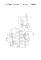
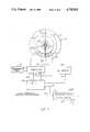
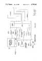
- FIG. 1is a diagrammatic illustration of a typical electric power substation incorporating the present invention
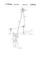
- FIG. 2is a view of a permanent or semi-permanent sensor module embodying the present invention being mounted on a transmission line;
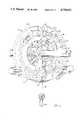
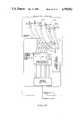
- FIG. 3is an enlarged, perspective view of a sensor module mounted on a conductor
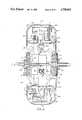
- FIG. 4is a view of the sensor module of FIG. 3 in a cross section through the plane of the conductor;
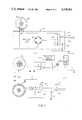
- FIG. 5is a general block diagram of the sensor module electronics
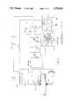
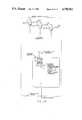
- FIG. 6is a schematic diagram illustrating the power supply and rechargeable power back-up system of the present invention.
- FIG. 7is a schematic diagram of the voltage sensing means of the invention.
- FIG. 7Ais a schematic diagram of an alternate voltage sensing means
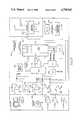
- FIG. 8is a detailed block diagram of portions of the module shown generally in FIG. 5;
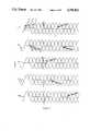
- FIG. 9is a graphical depiction of the voltage waveforms of the three cycles of each of a plurality of circuits connected to a substation bus;
- FIG. 10indicates the relationship of the sheets containing FIGS. 10A and 10B to form a single block diagram
- FIGS. 10A and 10Bform a composite block diagram of the ground station electronics
- FIGS. 11A and 11Bprovide a diagrammatic comparison of the monitoring systems of the prior art and the present invention.
- FIG. 1a diagrammatic representation of an electrical power substation enclosed by station fence 9, employing the present invention.
- a plurality of three phase circuitsare fed from a common bus comprising three phases 10, 12 and 14, each connected through circuit breaker 16 to transformer bank 18.
- the latteris fed by an incoming three-phase power circuit comprising three conductors denoted collectively by reference numeral 20.
- Sensor modules indicated generally by reference numeral 22, and having a structure and operation described later in more detail,are mounted upon each of the three phases of line 20, and of line 24, connecting transformer bank 18 to breakers 16.
- Conductors for each phase of all 3-phase circuits emanating from the substationare equipped with a line-mounted sensor module 22.
- Conventional circuit breakers 26are interposed in each circuit between its respective connection to the common bus phase and the associated sensor modules 22.
- each sensor moduleis programmed to transmit data in a 4.5 millisec burst at say the positive zero crossing of the voltage waveform for each phase of a circuit. Data transmissions are repeated at say every 7th cycle. On the same transmission frequency other circuit modules transmit on the 9th, 13th, 17th cycle etc. To accommodate larger number of circuits and 1 sec data refresh intervals, alternate circuit modules could be made to transmit on a second frequency in a 4.5 milli-sec. burst with respect to the negative voltage zero-crossing with repetition rates as above. This is done for all circuits tied to a given bus. For separate buses within a station additional frequencies are used, but, with the same synchronization and data burst control.
- each of modules 22includes means for both receiving and transmitting signals, as well as means for sensing the values of various parameters associated with the respective conductor upon which the sensor is mounted.
- the inventionis described herein as comprising RF transmitting and receiving means in each of sensors 22 and in a single ground station 29 in control house 28. Transmit and receive antennae of the ground station communication equipment are schematically indicated at 30 and 32, respectively. Corresponding communication equipment of the sensors is shown and described later. All sensors transmit data on a single frequency channel for reception by antenna 32; signals are transmitted by the ground station from antenna 30 on a second frequency channel for reception by the sensor receivers.
- the systemmay employ a 950 MHz FM "uplink" (from the ground station to the sensor modules) and a 928 MHz FM "downlink.”
- Each of modules 22is equipped to measure the values of voltage, current and phase angle of its associated conductor and may, if desired, be further equipped to measure other parameters such as frequency, conductor temperature, ambient temperature, conductor vibrations, etc.
- measurements of all parametersare made simultaneously by all modules 22 in the system at predetermined times established by a timing signal transmitted from the ground station and received by the modules.
- the timing signalfurther establishes "time slots" in which data from each of the modules 22 is transmitted in a predetermined sequence for reception at the ground station.
- Sensor module electronicsinclude a microprocessor, RAM, I/O, and timer components, as disclosed in parent application Ser. No. 484,681.
- the sampled values of the monitored parametersare digitized, stored in RAM, and communicated to the ground station during the established time interval as a burst of signals.
- the ground stationincludes a microprocessor to which signals received from modules 22 are supplied for further processing, such as calculation of total circuit and/or substation kilowatts, kilowatt hours, kilovars, etc.
- the datais then communicated to a central data receiving and control facility by a data link schematically indicated at 34, such as radio, land through the present invention; details of construction and operation appear in the balance of the disclosure.
- modules 22may be mounted upon energized, overhead conductors, such as that indicated at 35, easily and quickly by means of so-called "hot stick”36 manipulated by an individual on the ground or in a bucket truck.
- Hot stick 36includes an attachment tool 38 (to conventional hot-stick 36) which serves in the manner of an Allen wrench to engage portions of module 22 and effect opening and closing movement of two, hinged or pivoted connected sections of the module to permit mounting upon the conductor.
- FIGS. 3 and 4illustrate the configuration of the sensor module's exterior and interior, respectively.
- the modulecontains two lower sections 40 and two covers or upper sections 42, held together by bolts (not shown) passing through the covers into threads in the lower casting sections 40.
- An insulating gasketseparates the upper 42 and lower 40 housing sections so as not to form a short circuit loop surrounding the Rogowski coil 88 and the hinged power pick-off core 90 which extend around the torus in the upper and lower sections respectively.
- Each lower section 40is provided with a top hub 44 and a bottom hub 46, supported by relatively open spokes 48, FIG. 4.
- the sensor housing, generally indicated at 50,is secured to a clamping jaws assembly 52 by the open radial spokes 48.
- the diameter of the internal opening of the assembly dictated by neoprene type hub inserts 47,is variable and is selected for each specific power line conductor size.
- the assembly diametercan be chosen to accommodate different power cables form 0.5" to 21/2" in diameter.
- An R.F. impedance matching network 54, mounted near assembly 52is connected via coaxial cable parts 56 to a shielded transmitter and electronics shown generally at 58 inside module 22. Similar connections are made between the receiving antenna 60, if used, and communications board 61 inside module 22 for the alternative embodiment employing the time synchronized TDMA communications technique.
- FIG. 3Also shown in FIG. 3 is a fragment of hot-stick tool 36 with Allen wrench portion 38 extending into hole 62 in module 22.
- the hot-stickis turned in one direction to cause the hinged/pivoted sections of the module to open so that it can be placed over a conductor. Turning the hot-stick in the opposite direction causes the module to close over the conductor and clamp onto it tightly. The tool 36 can then be removed by simply pulling it away. Reinsertion and turning in the opposite direction will open the module and allow it to be removed from the transmission line. This placement/removal feature provides great flexibility in locating the modules in the transmission system.
- tubular rods 64 and 66which extend from sensor housing 50 and which terminate in metallized plastic spheres 68 and 70, respectively.
- the tubes and spheresare drawn at reduced scale for illustrative purposes.
- the tubular rods 64 and 66are attached to the cast aluminum sensor housing 50 by threaded inserts 72 and 74, respectively.
- the tubular rods 64 and 66 with spheres 68 and 70provide an increase in the effective surface area of the toroidal shaped sensor housing 50 which enhances the electrostatic charging capacity of the present invention.
- Solar photovolaic cells embedded on the surface of the tubular rods and spherescan also be used, if required, to further augment the charging energy when line current is below the threshold for electromagnetic powering of the circuitry.
- An electrical connection between surface areasis ensured by direct contact between the metallized rods 64 and 66 and the metal sensor housing 50.
- module 22is equipped with CPU processor board 76, RAM 78, PROM board 80 and optionally, electronically eraseable E2-PROM board 82.
- multi-tiered circuit boardsare used inside shielded compartments. Care is taken to avoid any 60 Hz short circuit loops.
- Address bus 84 and data bus 86interconnect the circuit cards.
- Power to operate the sensor module electronicsis normally derived from windings on a laminated iron core which surrounds the conductor.
- the coreis excited by the power line conductor current forming the single turn primary and the power supply windings 134 form the secondary coils of the power supply transformer.
- the core and windingare shown diagramatically in later Figures, and are divided into two sections for mounting in the two hinged/pivoted connected sections of the toroidal housing. Fragments of the upper portions of the two sections of the iron core, both indicated by reference numeral 88, are shown in the broken-away portions at the bottom of the housing.
- the pole faces of the two sections of core 88must close with a minimum controlled air gap and protected against corrosion.
- moisture-proof recess 90is provided around one pole face, and plastic shroud 92 surrounds and extends outwardly from the other pole face for mating engagement with recess 90 in the closed position of the module.
- Temperature probessuch as that indicated at 96, extend from contacting relation with the conductor to electrical connections within housing 50 in order to generate signals commensurate with the temperature of the conductor.
- ambient air temperature in the vicinity of the conductoris measured by probe 98, enclosed in a white shroud 100 which protects the probe from both direct solar exposure and heat generated by the conductor. Openings 102 permit air to flow freely over probe 98 and also ensure drainage of condensation.
- Both probes 96 and 98are thermally insulated from housing 50 to prevent the latter from effecting the sensed values.
- Rogowski coil 104which extends around the interior of housing 50 in side-by-side relation with an array of rechargeable batteries 106. Coil 104 and batteries 106 are held in place within sections 42 of the housing by hold-down clamps 108 and 110, respectively. Elements of the data sensing, receiving and transmitting electronics are indicated generally by reference numeral 112 within housing 50.
- the hub assemblyincludes outer ring 114, inner ring 116 insulated therefrom by oxide film layer 118, conductive rubber insert 120 selected in accordance with the diameter of the conductor, and optional synthetic rubber end hub caps 122 providing a moisture seal at each end of the hub where environmental conditions require. Alternatively, the insulated oxide film junction may be provided between the hub 44 and ring 114.
- the sensor module electronicsare shown in their overall configuration in FIG. 5. They comprise a power supply 124, signal processing, sampling, storage and control electronics 126, the various parameter sensors indicated by box 128, back-up energy storage and electrostatic and/electromagnetic charging electronics 130.
- the center tap 132 of the power pick-off coils 134 and 134', surrounding core sections 88 and 88', respectively,is connected to metallic housing 50 of sensor module 22, which in turn is connected through a capacitor provided by insulated outer and inner hub rings 114 and 116 to the power conductor via the conducting insert 120.
- the regulated power supply 124provides regulated ⁇ 5 volts to the electronics 126 via lead 136, 136' and an additional, switched 12 volts for transmitter and receiver 138 via lead 140.
- Electronics 126provides a transmitter control signal on line 139 to control the power supply to the transmitter, as well as receiver 141 in systems wherein the sensor modules also include a receiver, as described later.
- Sensors 128provide analog signals on lines indicated at 142 to electronics 126.
- the schematic electrical circuit diagram of the power supply 124 and back up energy storage 130is shown in FIG. 6.
- the power back up systemincludes a rechargeable energy source such as previously mentioned batteries 106, voltage and current monitoring circuitry provided as previously described, and battery float charging circuitry 144.
- a line current thresholdof approximately 15 amperes. Below this threshold level, the inductive power from line current is insufficient to operate the sensor module electronics and transmitter unless the power core cross-sectional area were significantly increased and therefore made much too heavy for hot-stick installation on live transmission lines.
- Power supply 146is shown with its major functional elements. During typical operation, i.e.
- Current threshold sensor 170comprising operational amplifier 172 and resistor 176 is fed current I on line 166 from the Rogowski coil.
- the measured current threshold referenceis set through resistor 176, and is determined by the requirements of the sensor module, e.g. 15 amperes.
- Current I on line 166is supplied to threshold comparator/detector 170 comprising amplifier 172 and resistor 174 which will detect current values above the threshold value as supplied through resistor 176.
- Comparator/detector 170provides an above/below threshold indicating signal on line 178 to the controller/clock 158.
- the threshold current valuepower is supplied by electromagnetic induction through power supply 146.
- poweris supplied to the sensor module by rechargeable batteries 106.
- the status of the conductor currenti.e. above/below threshold
- the controller 158will enable DC power from battery 106 to be supplied to regulator 152 on line 180.
- the DC voltage levels required by the module electronicsare thereby provided by the battery.
- controller 158will allow float charging of battery 106 and sensor module power is once again supplied directly by power supply 146.
- controller 158will discontinue power supplied by battery 106 and prevent any additional drain. Further zero current operation will be possible only after the line current exceeds the threshold setting and the battery is float or trickle charged.
- the means of the present invention for measuring the voltage on the conductoris illustrated in FIG. 7. Included in such means are insulation of the housing from the conductor, for example, the hub elements of the module, i.e., metal outer and inner rings 114 and 116, respectively, may be electrically insulated from one another by oxide film layer 118, indicated in FIG. 7 as a capacitor, and conductive, resilient insert 120, all previously described in connection with FIG. 4.
- the low input impedance of operational amplifier 184causes the charging current to flow from the high voltage conductor 10, through capacitor 188 and resistor 187, to the input of operational amplifier 184.
- the low impedance and high gain of amplifier 184insures that the potential of housing 50 is essentially the same as that of conductor 10, i.e., the potential between housing 50 and ground is the potential between ground and conductor 10.
- the insulating layer provided by metal oxide 118causes the charging current to flow through amplifier 184 rather than directly to housing 50. Therefore, operational amplifier 184 will provide an AC output voltage exactly proportional to the current through the skin of sensor module 22 to ground, which is directly proportional to the high voltage between conductor 10 and ground.
- the dimensions and material of the insulating layer 118 between inner and outer rings 114 and 116are selected to provide a capacitance value which would allow the charging current of the highest frequency voltage component to be measured to pass through to operational amplifier 184.
- Capacitor 188is relatively large, e.g., 5-10 MFd, to block any DC signals.
- Resistor 187is a current-limiting means to protect against fast rise-time surges.
- Diodes 190 and 192clamp the voltage across resistance-capacitance 187-188; similarly, diodes 194 and 196 clamp the voltage across the inputs of amplifier 184.
- Metal oxide surge suppressor 198protects the circuit components against damage due to momentary transients.
- the output signal representing the voltage valueis coupled, through electronics 126 (FIG. 5) to transmitter 138.
- the latteris coupled through RF shunting capacitor 200, to outer ring 114 which is connected directly to housing 50 and through capacitor formed at 118 to the conductor 10 at the RF transmission frequency of 928 MHz.
- the components of the voltage measuring systems indicated in FIG. 7are mounted within shielded (metal) enclosure 202 within housing 50.
- FIG. 7AAn alternate means for measuring voltage on conductor 10, disclosed in parent application Ser. No. 484,681, is illustrated in FIG. 7A.
- Arcuate, electrically conducting plates or discs 201 and 203are attached to the exterior of the metallic housing of module 22 with a thin layer of insulation between each plate and the housing surface, thereby providing a capacitance at each plate.
- C dg and V dgrepresent the capacitance and voltage, respectively, between discs 201 and 203, which are connected by lead 205, and earth.
- C dhrepresents the capacitance between the discs and the module housing, which is electrically connected to and thus at the potential of conductor 10.
- High impedance amplifier 207measures the voltage between the discs and housing (V dh ), which is proportional to the voltage between the discs and earth V dc ), since the circuit is configured as a voltage divider.
- the input and feedback impedance of the amplifierare represented by Z; and Z f , respectively.
- the measured voltage V o between the output of high impedance amplifier 207 and ground potentialis proportional to the voltage across the discs and housing V dh . This means of voltage measurement does not provide the level of accuracy of the FIG. 7 system, but is less expensive and may be acceptable for some applications.
- the inventionprovides a sensor module, adapted for hot-stick mounting on an energized power conductor, capable of measuring voltage as well as current on the power conductor (and other parameters, when desired).
- the phase angles and frequencymay also be determined, thereby permitting quantities such as watts and watt-hours, etc. (in any desired combination of parameters) to be derived.
- the module electronicsmay be operated by power taken directly from the conductor upon which the module is mounted or, when current on an energized conductor falls below a predetermined threshold value (including zero current conditions), by back-up power means independent of the conductor.
- the parameter valuesare transmitted from the modules to a ground station and systems which may be employed for transmitting signals in a time-synchronized manner from modules sensing the parameters on each phase of a three phase circuit, or from all circuits of an entire substation will now be described.
- Rogowski coil 104is connected to input amplifier 220 through current range select resistors 222.
- the voltage sensoris connected through capacitor 188 to low impedanoe operational amplifier 184 with feedback capacitor 186, as previously described, to provide an output signal in phase with the line-to-neutral voltage.
- Additional amplifierssuch as that indicated at 230 are provided for measurement of additional parameters, such as conductor temperature, ambient temperature, conductor vibrations, etc.
- the output of each of the parameter-measuring amplifiersis connected through multiplexer 231 for comparison with the output of digital/analog converter means 232, which receives an input from voltage reference 234, at comparator 236, under the control of digital computer 238.
- the lattermay be, for example, a Motorola CMOS 6805 microprocessor having I/O, RAM and timer components.
- Programmable read only memory 240is connected to the computer CPU for storing the program.
- Current and voltage zero crossing detectionis provided by amplifiers 242 and 244, respectively, each having one input connected to the output of the respective current and voltage measuring amplifiers, and the other input connected to ground. The outputs of both zero crossing detectors are connected directly to microprocessor 238 for phase measurement.
- the signals from voltage zero crossing detector 244may be used for synchronization of data transmissions by transmitter 138 without requiring a receiver in the sensor module and a transmitter at the ground station.
- the voltages on each phase of a total of five 3 phase circuitsare indicated with respect to time. Transmissions from each of the three individual sensor modules of circuit 1 (one mounted on the conductor of each phase) are made, for example, within 4.5 millisecond (or less) bursts M a11 , M b11 , M c11 following each positive-going zero-crossing of the voltage on the associated conductor at a first selected frequency f 1 .
- a coded message in the form of a burst of signals indicative of the parameters measured at that timemay be transmitted by the transmitter of the module on phase A during time interval M a11 ; the messages from the modules mounted on the conductors of phases B and C are transmitted during times M a11 and M c11 , respectively.
- Messagesmay be transmitted, for example, every seventh cycle, leaving ample time for data collection and processing between transmissions.
- the transmit burst control signalsare communicated from microprocessor 238 to transmitter 138 via line 242.
- transmissionsmay be synchronized to prevent overlap by proper spacing of transmissions and/or selection of broadcast frequencies.
- transmissions from the modules of circuit 2may be initiated by the negative-going zero crossings on a second frequency, thus permitting transmissions overlapped in time with those from the modules of circuit 1.
- the first message from phase A of circuit 2is transmitted during time M a21 , and those from phases B and C during times M b21 and M c21 , respectively. Transmissions may be made on the first frequency from other circuits during the periods when the modules of circuit 1 are not transmitting.
- Circuit 3for example, may transmit on the first frequency at times M a31 , M b31 and M c31 every eleventh cycle.
- the second messages from the circuit 1 modulesare transmitted at times M a12 , M b12 and M c12 , after the seventh cycle.
- transmissions from the three modules of each circuitare completed within one full cycle (as would be the case for successive 4.5 millisecond transmissions, since a full cycle takes 16.7 milliseconds at 60 Hz) then transmission from each circuit would be spaced by a number of cycles at least equal to the number of circuits.
- different numbers of cycle spacings between transmissionsshould be chosen for the circuits and no two numbers may have a common denominator. For example, transmissions from 5 circuits on a single frequency could be spaced by 7,11,13,17 and 19 cycles respectively.
- a transceiver systemwhich permits time synchronized, sequential data transmission from a relatively large number of modules, e.g., all modules necessary for monitoring an entire substation such as that of FIG. 1, to a single ground station on a single broadcast frequency.
- the zero crossing detectors previously described for controlling the timing of transmissions from the three modules of one circuitmay also be used to provide basic synchronization with TDMA coded timing signals transmitted from the ground station and received at the module by receiver 141.
- Each moduleis assigned an identifying number which is selected initially through module 244.
- the digitized data representing the parameter valuesis assembled into appropriate messages, encoded in Manchester code by encoder 246 and supplied to transmitter 138 via line 248 for transmission in assigned time slots designated by TDMA data burst control signals received by receiver 141.
- the timing signals from the ground stationare passed on from receiver 141 to demodulator 250 (which can be part of the receiver 141).
- the demodulated TDMA signalcontains information on the assigned time slot for transmission by the particular sensor module.
- the signalis passed through CRC check module 252, for error detection and the pulse code is detected by module 254, providing the microprocessor with information to control the transmitter burst timing.
- FIG. 10A block diagram of the ground station electronics used at a substation to receive transmissions from all sensor modules which perform the monitoring function, and processing the signals received from such modules, is shown in FIG. 10.
- sensor modules 22include self-contained control of transmission timing, the ground station requires only receiver means (i.e., the modules require no receiver and the ground station requires no transmitter). If, on the other hand, timing of transmissions by the respective modules is controlled to take place in assigned time slots, in the manner previously mentioned, a transmitter is provided at the ground station and a receiver in each module.
- the Manchester coded signals transmitted by the individual sensor modulesare received through antenna 32 at receiver 256, passed through serial port 258 of the communication board and CRC error check module 260 to CPU 262 through the data bus.
- An I/O interfaceis provided for receiving external signals for implementing the functions of a conventional remote terminal substation unit, as indicated by the labeled blocks connected to CPU 262.
- Keyboard interface 264is connected to CPU 262 for local control of parameters to be displayed on a single line alpha numeric display device 266.
- CPU 262is also provided with an RS 232 port 268 for loading and unloading personality tables, or for a man-machine interface using a portable microcomputer, such as an IBM-XT or a COMPAQ.
- CPU 262is provided in the usual manner with RAM 270, PROM 272 and Electronically Eraseable PROM 274, the latter being used to display the scale factors and personality tables for the sensor modules through RS 232 interface 268.
- the micro-code for claculating the various output parametrersis stored in PROM 272.
- the combined remote terminal unitis equipped to receive direct, hard-wired inputs from conditioned, conventional current and potential transformers 276 and 278, respectively.
- Analog signals proportional to the input current and voltageare fed to conditioning amplifiers 280, sample-and-hold circuitry 282 and thence to multiplexer 284 in a manner similar to the processing of analog signals in the sensor modules, as previously described.
- A/D converter 286 and analog metering control board 288transfer the digitized signals to CPU 262 where the data is processed in a manner similar to the sensor module data.
- ground station electronicsis amplified to some extent in previously mentioned copending application Ser. No. 859,487 and includes all elements required for receiving and processing signals transmitted by the various sensor modules.
- the ground stationfurther includes time division multiple access (TDMA) message synchronization signals from CPU 262, and connected through pulse code modulator 292 to transmitter 294.
- TDMAtime division multiple access
- the signals assigning transmission times to the various modulesare then transmitted from the ground station via antenna 30 and received at the modules by receiving antenna 60 provided for such purpose.
- FIGS. 11A and 11BA direct comparison between substation monitoring as conventionally performed by hard-wired current and potential transformers, and by the approach of the present invention is provided by FIGS. 11A and 11B.
- the conductors of each phase of a single circuitare indicated in FIG. 11A by reference numerals 300, 301 and 302, and in FIG. 11B by numerals 300', 301', and 302', it being understood that the number of circuits and conductors would be dependent on the size of the station.
- Such transformersrequire massive and costly porcelain bushings, support structures and concrete foundations.
- auxiliary transformersin a control house, which in turn are connected through test switches to discrete transducers for each quantity to be measured.
- Transducers so labeled in FIG 11Aare connected through terminal blocks to a separate, remote terminal unit (RTU) also so labeled.
- RTUremote terminal unit
- sensor modules 22are mounted upon each phase of the circuit and measure current, voltage and phase angle in the manner described.
- the modulesmay be mounted directly upon energized conductors, without interruption of power. Sequential transmission of data bursts from all modules at the substation is controlled by either of the two disclosed methods, i.e., by synchronization with voltage zero crossings and bursting data to the ground station after a pre-selected number of cycles have elapsed for each module, or by providing a ground transmitter and a receiver in each module for coded time-synchronization signals.
- Signals indicating the sensed parameters on each phase of all circuits at the substationare received and processed at a single remote terminal interface and the same microprocessor is used to perform conventional alarm, status, sequence-of-events, select-before-operate, other analog monitoring, and pulse accumulator functions of a conventional Remote Terminal Unit, i.e., the ground station acts as a combined Remote Terminal Unit (CRTU).
- CRTURemote Terminal Unit
- the present inventionprovides a complete monitoring system which is superior in performance and flexibility to conventional systems while, at the same time, being vastly smaller, lighter, less costly and more convenient to install, remove, repair, etc.
- the comparisonis more dramatic when it is noted that all of the bulky and expensive equipment indicated in FIG. 11A must be duplicated in its entirety for every circuit monitored at a substation, while only the sensor modules are duplicated (one for each conductor) in FIG. 11B regardless of the number of circuits. That is, only one CRTU, having a size essentially the same as that of the RTU of the conventional system, is required in the present system, thereby totally eliminating all the measurement transformers, test switches, transducers, terminal blocks, hard wiring and supporting structures required for every circuit in conventional systems.
- a sensor modulecould have a weight of less than 20 pounds, while the corresponding prior art equipment would weigh several thousand pounds.
Landscapes
- Engineering & Computer Science (AREA)
- Physics & Mathematics (AREA)
- Power Engineering (AREA)
- General Physics & Mathematics (AREA)
- Computer Networks & Wireless Communication (AREA)
- Mathematical Physics (AREA)
- Acoustics & Sound (AREA)
- Remote Monitoring And Control Of Power-Distribution Networks (AREA)
- Measuring Instrument Details And Bridges, And Automatic Balancing Devices (AREA)
- Arrangements For Transmission Of Measured Signals (AREA)
- Supply And Distribution Of Alternating Current (AREA)
- Testing Of Short-Circuits, Discontinuities, Leakage, Or Incorrect Line Connections (AREA)
- Gas-Insulated Switchgears (AREA)
- Locating Faults (AREA)
- Measurement Of Resistance Or Impedance (AREA)
- Testing Electric Properties And Detecting Electric Faults (AREA)
- Protection Of Transformers (AREA)
- Testing Or Calibration Of Command Recording Devices (AREA)
- Time-Division Multiplex Systems (AREA)
- Measuring Temperature Or Quantity Of Heat (AREA)
- Measurement Of Mechanical Vibrations Or Ultrasonic Waves (AREA)
- Electrostatic Charge, Transfer And Separation In Electrography (AREA)
- Elimination Of Static Electricity (AREA)
- Control Or Security For Electrophotography (AREA)
- Monitoring And Testing Of Transmission In General (AREA)
- Communication Control (AREA)
- Emergency Protection Circuit Devices (AREA)
Abstract
Description
This application is a continuation-in-part of copending applications Ser. No. 484,681, filed April 13, 1983 and issued as U.S. Pat. No. 4,689,742, and Ser. No. 795,226 filed Nov. 5, 1985 now abaandoned.
This invention relates to apparatus for measuring operating parameters of high voltage power conductors and, more particularly, to systems employing sensors which are mounted on overhead power transmission lines for measuring all parameters necessary to monitor operation of single phase circuits, three phase circuits, and an entire electrical power substation. The sensors normally derive their power as a result of current flowing through the power conductor, and the invention further relates to back-up power means for operating the sensors when there is little or no current flow through the conductor.
Various power line sensors have been disclosed in the prior art. For example, the sensors of U.S. Pat. Nos. 3,428,896, 3,633,191, 4,158,810, 4,268,818 and 4,384,289 have been proposed for dynamic line rating of electrical power transmission lines. The power line sensor systems available in the prior art measure certain quantities associated with the operation of an individual overhead conductor, namely, current flow in the conductor, conductor temperature and ambient temperature. The limited information gathered by a single sensor module is transmitted to a local ground station dedicated to that sensor module. Data from various ground receivers is transmitted to a central control station where the information is analyzed.
Sensor modules of the prior art, although providing a means of measuring certain operating parameters of individual conductors, do not provide a means for simultaneous measurement of multiple parameters and communication of data from several sensor modules to a single ground receiving station. Thus, prior art sensors for monitoring transmission lines have not had the capability of simultaneously and accurately measuring voltage, current and phase angle on a single phase or cooperatively on all conductors of a 3-phase circuit. Likewise, prior art systems employing line-mounted sensor modules do not have the capability of measuring and communicating all operating parameters involved in monitoring an entire substation through a single, microprocessor controlled ground station receiving data from a plurality of sensors. It has therefore remained necessary to provide substation monitoring in the conventional manner, i.e., by means of individual current and potential transformers on each conductor at a substation where each transformer is hard-wired to auxiliary transformers on the ground wherein the signals are converted to a level compatible with various transducers. Individual transducers are required to measure each parameter, such as voltage, current, kilowatts. These signals then pass through an array of test switches and terminal blocks which in turn are hard-wired to a Remote Terminal Unit (RTU).
It is a principal object of the present invention to provide a sensor module for mounting directly upon an energized power conductor and capable of measuring simultaneously the voltage, current, frequency, phase angle and other parameters on the associated conductor and communicating the values thereof to a receiving station. The received signals may be further processed to provide other data associated with a single phase or with one or more 3-phase circuits.
It is a further object to provide an integrated system for monitoring parameters associated with operation of an entire electrical power substation using only line-mounted modules, each capable of simultaneously sensing the voltage, current and phase angle on the associated conductor at a predetermined time and communicating the measured quantities to a single ground station microprocessor. The sensor modules, of course, are of a type which may be mounted directly upon energized conductors, requiring no shut down of the circuit during installation. Furthermore, the signals communicated from the modules to the ground station are in a condition for use directly by the microprocessor, thereby eliminating the need for auxiliary transformers, transducers, and the like, necessary for signal conditioning and processing in prior art substation monitoring systems.
Prior art sensor modules, such as the toroidal-shaped modules of previously mentioned U.S. Pat. No. 4,384,289, derive their operating power directly from the conductors upon which they are mounted. Consequently, they are operable only when the line current of the conductor is at or above the minimum value necessary to power the sensor electronics. In a substation monitoring system of the type contemplated by the present invention, it is necessary that the sensor modules also be operable when line currents are below the threshold level, i.e., for monitoring very low current conditions or detection of energized conductors with zero current flow. Therefore, it is an ancillary object of the invention to provide a reliable power back-up system, requiring essentially no removal and/or replacement of batteries for recharging, for operating line-mounted sensor modules.
In a system where a plurality of modules transmit data to a single receiver it is desireable to provide means for insuring that more than one sensor is not transmitting at any given time. It has been proposed to transmit signals in bursts of finite duration at random times, but there is still the possibility that more than one sensor will be transmitting at a given time. It is an additional object of the present invention to provide means for time synchronizing data transmissions from a plurality of sensor modules so that no two modules are transmitting at the same time.
Furthermore, it is an object of the invention to achieve this through self-contained means within each module precluding need for communication between modules or requiring a synchronizing signal from the ground station, called the combined CRTU.
Other objects, related to the foregoing, will in part be obvious and will in part appear hereinafter.
The present invention contemplates a power monitoring system comprising a sensor module capable of simultaneously measuring the voltage, current and phase angle and other parameters of a power conductor (or in its vicinity e.g. ambient conditions) upon which the module is mounted and for communicating such data to a ground station. The invention may be expanded to include systems wherein one such module is mounted upon each conductor to be monitored at a power substation with self-contained synchronization means or means such as, RF receivers of power line carrier coupling provided to cause all sensors in the system to measure the values of voltage, current, phase angle and frequency, on the associated conductors simultaneously at predetermined times. The sensor modules are connected by a communications link, such as RF transmitters and receivers, to the ground station and are adapted to convey signals commensurate with the measured parameters sequentially to appropriate signal receiving means on the ground. The signals in their as-received condition are suitable for supply to a micro-processor wherein all desired quantities which may be derived from the values of voltage, current and phase angle of the various conductors, such as, megawatts, megawatt-hours, megavars, power factor, etc., are developed and the resulting information is communicated with other information in a manner similar to a conventional RTU but employing a single microprocessor. Thus, the invention eliminates the need not only for current and potential transformers wired from the respective conductors to auxiliary transformers on the ground, but also an array of transducers, test switches, terminal blocks and hard wiring representing literally tons of equipment previously required for monitoring operation of an electrical power substation.
The sensor modules also preferably include electrostatioally or electromagnetically line powered, rechargeable battery back-up facility for powering the module electronics when there is minimal or zero current on the conductor upon which the module is mounted. Current sensing circuitry in the module monitors the level of current on the conductor to establish whether the current is above or below a predetermined threshold value. When current is above this value, the sensor is powered by electromagnetic induction from the conductor, which also serves to float charge the battery. When line current is below the threshold value, or when the conductor is energized but current is zero, as determined by voltage sensing circuitry, power is supplied to the sensor by the battery. If the zero current condition persists beyond a predetermined time limit, battery control circuitry and a processor in the sensor module operate to reduce the frequency of data transmission from the module to the ground station receiver, thus conserving battery power. If battery voltage drops below a predetermined level, all battery-powered transmission is stopped until the batteries are sufficiently recharged. Also, when current on the conductor is at or above zero but below the threshold level, the battery is float charged electrostatically between data transmissions.
FIG. 1 is a diagrammatic illustration of a typical electric power substation incorporating the present invention;
FIG. 2 is a view of a permanent or semi-permanent sensor module embodying the present invention being mounted on a transmission line;
FIG. 3 is an enlarged, perspective view of a sensor module mounted on a conductor;
FIG. 4 is a view of the sensor module of FIG. 3 in a cross section through the plane of the conductor;
FIG. 5 is a general block diagram of the sensor module electronics;
FIG. 6 is a schematic diagram illustrating the power supply and rechargeable power back-up system of the present invention;
FIG. 7 is a schematic diagram of the voltage sensing means of the invention;
FIG. 7A is a schematic diagram of an alternate voltage sensing means;
FIG. 8 is a detailed block diagram of portions of the module shown generally in FIG. 5;
FIG. 9 is a graphical depiction of the voltage waveforms of the three cycles of each of a plurality of circuits connected to a substation bus;
FIG. 10 indicates the relationship of the sheets containing FIGS. 10A and 10B to form a single block diagram;
FIGS. 10A and 10B form a composite block diagram of the ground station electronics; and
FIGS. 11A and 11B provide a diagrammatic comparison of the monitoring systems of the prior art and the present invention.
Referring now to the drawings, in FIG. 1 is shown a diagrammatic representation of an electrical power substation enclosed by station fence 9, employing the present invention. A plurality of three phase circuits, numbered 1-8, are fed from a common bus comprising threephases circuit breaker 16 totransformer bank 18. The latter is fed by an incoming three-phase power circuit comprising three conductors denoted collectively by reference numeral 20. Sensor modules indicated generally byreference numeral 22, and having a structure and operation described later in more detail, are mounted upon each of the three phases of line 20, and of line 24, connectingtransformer bank 18 tobreakers 16. Conductors for each phase of all 3-phase circuits emanating from the substation are equipped with a line-mountedsensor module 22. Conventional circuit breakers 26 are interposed in each circuit between its respective connection to the common bus phase and the associatedsensor modules 22.
In one embodiment each sensor module is programmed to transmit data in a 4.5 millisec burst at say the positive zero crossing of the voltage waveform for each phase of a circuit. Data transmissions are repeated at say every 7th cycle. On the same transmission frequency other circuit modules transmit on the 9th, 13th, 17th cycle etc. To accommodate larger number of circuits and 1 sec data refresh intervals, alternate circuit modules could be made to transmit on a second frequency in a 4.5 milli-sec. burst with respect to the negative voltage zero-crossing with repetition rates as above. This is done for all circuits tied to a given bus. For separate buses within a station additional frequencies are used, but, with the same synchronization and data burst control.
As described later in more detail, in a second configuration each ofmodules 22 includes means for both receiving and transmitting signals, as well as means for sensing the values of various parameters associated with the respective conductor upon which the sensor is mounted. Although other types of communications links may be utilized, the invention is described herein as comprising RF transmitting and receiving means in each ofsensors 22 and in asingle ground station 29 incontrol house 28. Transmit and receive antennae of the ground station communication equipment are schematically indicated at 30 and 32, respectively. Corresponding communication equipment of the sensors is shown and described later. All sensors transmit data on a single frequency channel for reception byantenna 32; signals are transmitted by the ground station fromantenna 30 on a second frequency channel for reception by the sensor receivers. For example, the system may employ a 950 MHz FM "uplink" (from the ground station to the sensor modules) and a 928 MHz FM "downlink."
Each ofmodules 22 is equipped to measure the values of voltage, current and phase angle of its associated conductor and may, if desired, be further equipped to measure other parameters such as frequency, conductor temperature, ambient temperature, conductor vibrations, etc.
In the second communication approach described for the sensor modules employing Time Division Multiple Access, measurements of all parameters are made simultaneously by allmodules 22 in the system at predetermined times established by a timing signal transmitted from the ground station and received by the modules. The timing signal further establishes "time slots" in which data from each of themodules 22 is transmitted in a predetermined sequence for reception at the ground station.
Sensor module electronics include a microprocessor, RAM, I/O, and timer components, as disclosed in parent application Ser. No. 484,681. The sampled values of the monitored parameters are digitized, stored in RAM, and communicated to the ground station during the established time interval as a burst of signals. The ground station includes a microprocessor to which signals received frommodules 22 are supplied for further processing, such as calculation of total circuit and/or substation kilowatts, kilowatt hours, kilovars, etc. The data is then communicated to a central data receiving and control facility by a data link schematically indicated at 34, such as radio, land through the present invention; details of construction and operation appear in the balance of the disclosure.
As illustrated in FIG. 2,modules 22 may be mounted upon energized, overhead conductors, such as that indicated at 35, easily and quickly by means of so-called "hot stick"36 manipulated by an individual on the ground or in a bucket truck.Hot stick 36 includes an attachment tool 38 (to conventional hot-stick 36) which serves in the manner of an Allen wrench to engage portions ofmodule 22 and effect opening and closing movement of two, hinged or pivoted connected sections of the module to permit mounting upon the conductor. One of many possible mechanical embodiments of the mounting means, details of which form no part of the present invention, may be found in parent application Ser. No. 484,681.
FIGS. 3 and 4 illustrate the configuration of the sensor module's exterior and interior, respectively. As shown in FIG. 3, the module contains twolower sections 40 and two covers or upper sections 42, held together by bolts (not shown) passing through the covers into threads in thelower casting sections 40. An insulating gasket separates the upper 42 and lower 40 housing sections so as not to form a short circuit loop surrounding theRogowski coil 88 and the hinged power pick-off core 90 which extend around the torus in the upper and lower sections respectively. Eachlower section 40 is provided with atop hub 44 and abottom hub 46, supported by relativelyopen spokes 48, FIG. 4. The sensor housing, generally indicated at 50, is secured to a clampingjaws assembly 52 by the openradial spokes 48. The diameter of the internal opening of the assembly dictated by neoprene type hub inserts 47, is variable and is selected for each specific power line conductor size. The assembly diameter can be chosen to accommodate different power cables form 0.5" to 21/2" in diameter. An R.F.impedance matching network 54, mounted nearassembly 52 is connected via coaxial cable parts 56 to a shielded transmitter and electronics shown generally at 58 insidemodule 22. Similar connections are made between the receivingantenna 60, if used, and communications board 61 insidemodule 22 for the alternative embodiment employing the time synchronized TDMA communications technique. Also shown in FIG. 3 is a fragment of hot-stick tool 36 withAllen wrench portion 38 extending intohole 62 inmodule 22. The hot-stick is turned in one direction to cause the hinged/pivoted sections of the module to open so that it can be placed over a conductor. Turning the hot-stick in the opposite direction causes the module to close over the conductor and clamp onto it tightly. Thetool 36 can then be removed by simply pulling it away. Reinsertion and turning in the opposite direction will open the module and allow it to be removed from the transmission line. This placement/removal feature provides great flexibility in locating the modules in the transmission system.
Further illustrated in FIG. 3 are metallized plastic,tubular rods sensor housing 50 and which terminate in metallized plastic spheres 68 and 70, respectively. The tubes and spheres are drawn at reduced scale for illustrative purposes. Thetubular rods aluminum sensor housing 50 by threadedinserts tubular rods sensor housing 50 which enhances the electrostatic charging capacity of the present invention. Solar photovolaic cells embedded on the surface of the tubular rods and spheres can also be used, if required, to further augment the charging energy when line current is below the threshold for electromagnetic powering of the circuitry. An electrical connection between surface areas is ensured by direct contact between the metallizedrods metal sensor housing 50. In addition to the previously described elements,module 22 is equipped withCPU processor board 76,RAM 78,PROM board 80 and optionally, electronically eraseable E2-PROM board 82. For maximum packing density, multi-tiered circuit boards are used inside shielded compartments. Care is taken to avoid any 60 Hz short circuit loops.Address bus 84 anddata bus 86 interconnect the circuit cards.
Power to operate the sensor module electronics is normally derived from windings on a laminated iron core which surrounds the conductor. The core is excited by the power line conductor current forming the single turn primary and thepower supply windings 134 form the secondary coils of the power supply transformer. The core and winding are shown diagramatically in later Figures, and are divided into two sections for mounting in the two hinged/pivoted connected sections of the toroidal housing. Fragments of the upper portions of the two sections of the iron core, both indicated byreference numeral 88, are shown in the broken-away portions at the bottom of the housing. Whenmodule 22 is mounted on the conductor, the pole faces of the two sections ofcore 88 must close with a minimum controlled air gap and protected against corrosion. For this purpose, moisture-proof recess 90 is provided around one pole face, andplastic shroud 92 surrounds and extends outwardly from the other pole face for mating engagement with recess 90 in the closed position of the module.
Current flow through the conductor is measured byRogowski coil 104, which extends around the interior ofhousing 50 in side-by-side relation with an array ofrechargeable batteries 106.Coil 104 andbatteries 106 are held in place within sections 42 of the housing by hold-down clamps 108 and 110, respectively. Elements of the data sensing, receiving and transmitting electronics are indicated generally by reference numeral 112 withinhousing 50. The hub assembly includesouter ring 114,inner ring 116 insulated therefrom byoxide film layer 118,conductive rubber insert 120 selected in accordance with the diameter of the conductor, and optional synthetic rubber end hub caps 122 providing a moisture seal at each end of the hub where environmental conditions require. Alternatively, the insulated oxide film junction may be provided between thehub 44 andring 114.
The sensor module electronics are shown in their overall configuration in FIG. 5. They comprise apower supply 124, signal processing, sampling, storage andcontrol electronics 126, the various parameter sensors indicated bybox 128, back-up energy storage and electrostatic and/electromagnetic charging electronics 130.
Thecenter tap 132 of the power pick-offcoils 134 and 134', surroundingcore sections 88 and 88', respectively, is connected tometallic housing 50 ofsensor module 22, which in turn is connected through a capacitor provided by insulated outer and inner hub rings 114 and 116 to the power conductor via the conductinginsert 120. Theregulated power supply 124 provides regulated ±5 volts to theelectronics 126 vialead 136, 136' and an additional, switched 12 volts for transmitter andreceiver 138 vialead 140.Electronics 126 provides a transmitter control signal online 139 to control the power supply to the transmitter, as well asreceiver 141 in systems wherein the sensor modules also include a receiver, as described later.Sensors 128 provide analog signals on lines indicated at 142 toelectronics 126.
The schematic electrical circuit diagram of thepower supply 124 and back upenergy storage 130 is shown in FIG. 6. The power back up system includes a rechargeable energy source such as previously mentionedbatteries 106, voltage and current monitoring circuitry provided as previously described, and batteryfloat charging circuitry 144. Without the apparatus of the present invention, measurement of transmission line parameters was not possible below a line current threshold of approximately 15 amperes. Below this threshold level, the inductive power from line current is insufficient to operate the sensor module electronics and transmitter unless the power core cross-sectional area were significantly increased and therefore made much too heavy for hot-stick installation on live transmission lines.Power supply 146 is shown with its major functional elements. During typical operation, i.e. with line current above the minimum threshold value, power is derived through electromagnetic induction using the magnetic field generated as a result of current flowing throughconductor 12. The hingediron core 88, with power pick-offcoils 134 providing the secondary, and the line conductor forming the single turn primary of a power transformer, supplies all internal power to the sensor module. Winding 134 is connected to bridgerectifier 148 to provide unregulated DC power. Protection against power surges is provided by aGEMOV device 150. The output ofrectifier 148 is supplied toDC regulator 152 which supplies the DC voltages required by sensor module electronics onlines Capacitor 156 is connected between the regulator and the controller/clock circuitry 158.
As previously described, current in the conductor is measured byRogowski coil 104.Current threshold sensor 170, comprisingoperational amplifier 172 andresistor 176 is fed current I online 166 from the Rogowski coil. The measured current threshold reference is set throughresistor 176, and is determined by the requirements of the sensor module, e.g. 15 amperes. Current I online 166 is supplied to threshold comparator/detector 170 comprisingamplifier 172 andresistor 174 which will detect current values above the threshold value as supplied throughresistor 176. Comparator/detector 170 provides an above/below threshold indicating signal online 178 to the controller/clock 158.
Above the threshold current value, power is supplied by electromagnetic induction throughpower supply 146. Below the threshold value, power is supplied to the sensor module byrechargeable batteries 106. The status of the conductor current (i.e. above/below threshold) is supplied to battery controller/clock circuitry 158 by comparator/detector 170 online 178. When the below-threshold condition is sensed, thecontroller 158 will enable DC power frombattery 106 to be supplied toregulator 152 online 180. The DC voltage levels required by the module electronics are thereby provided by the battery. When the conductor current reaches the threshold level,controller 158 will allow float charging ofbattery 106 and sensor module power is once again supplied directly bypower supply 146. For periods of operation at zero current, with line voltage present, exceeding a preset (through PROM) duration the frequency of the transmission bursts is reduced to conserve battery energy. If, during sustained periods of zero current on the conductor, the battery voltage falls below a predeterminedsafe value controller 158 will discontinue power supplied bybattery 106 and prevent any additional drain. Further zero current operation will be possible only after the line current exceeds the threshold setting and the battery is float or trickle charged.
The means of the present invention for measuring the voltage on the conductor is illustrated in FIG. 7. Included in such means are insulation of the housing from the conductor, for example, the hub elements of the module, i.e., metal outer andinner rings oxide film layer 118, indicated in FIG. 7 as a capacitor, and conductive,resilient insert 120, all previously described in connection with FIG. 4. An integrator, indicated generally at 182, consisting ofoperational amplifier 184 and gaincontrol feedback capacitor 186, has one input connected throughresistor 187 andcapacitor 188 toinner ring 116, and the other to the outer skin ofhousing 50 ofmodule 22. The low input impedance ofoperational amplifier 184 causes the charging current to flow from thehigh voltage conductor 10, throughcapacitor 188 andresistor 187, to the input ofoperational amplifier 184. The low impedance and high gain ofamplifier 184 insures that the potential ofhousing 50 is essentially the same as that ofconductor 10, i.e., the potential betweenhousing 50 and ground is the potential between ground andconductor 10. The insulating layer provided bymetal oxide 118, causes the charging current to flow throughamplifier 184 rather than directly tohousing 50. Therefore,operational amplifier 184 will provide an AC output voltage exactly proportional to the current through the skin ofsensor module 22 to ground, which is directly proportional to the high voltage betweenconductor 10 and ground. The dimensions and material of the insulatinglayer 118 between inner andouter rings operational amplifier 184.
An alternate means for measuring voltage onconductor 10, disclosed in parent application Ser. No. 484,681, is illustrated in FIG. 7A. Arcuate, electrically conducting plates ordiscs module 22 with a thin layer of insulation between each plate and the housing surface, thereby providing a capacitance at each plate. In the drawing, Cdg and Vdg represent the capacitance and voltage, respectively, betweendiscs lead 205, and earth. Cdh represents the capacitance between the discs and the module housing, which is electrically connected to and thus at the potential ofconductor 10.High impedance amplifier 207 measures the voltage between the discs and housing (Vdh), which is proportional to the voltage between the discs and earth Vdc), since the circuit is configured as a voltage divider. The input and feedback impedance of the amplifier are represented by Z; and Zf, respectively. The measured voltage Vo between the output ofhigh impedance amplifier 207 and ground potential is proportional to the voltage across the discs and housing Vdh. This means of voltage measurement does not provide the level of accuracy of the FIG. 7 system, but is less expensive and may be acceptable for some applications.
From the foregoing, it is apparent that the invention provides a sensor module, adapted for hot-stick mounting on an energized power conductor, capable of measuring voltage as well as current on the power conductor (and other parameters, when desired). By providing current and voltage zero-crossing detection, the phase angles and frequency may also be determined, thereby permitting quantities such as watts and watt-hours, etc. (in any desired combination of parameters) to be derived. The module electronics may be operated by power taken directly from the conductor upon which the module is mounted or, when current on an energized conductor falls below a predetermined threshold value (including zero current conditions), by back-up power means independent of the conductor. The parameter values are transmitted from the modules to a ground station and systems which may be employed for transmitting signals in a time-synchronized manner from modules sensing the parameters on each phase of a three phase circuit, or from all circuits of an entire substation will now be described.
Referring now to FIG. 8, current and voltage on the conductor at a predetermined point in time are sensed simultaneously byRogowski coil 104 andhousing 50, respectively, in the manner previously described.Rogowski coil 104 is connected to inputamplifier 220 through current rangeselect resistors 222. The voltage sensor is connected throughcapacitor 188 to low impedanoeoperational amplifier 184 withfeedback capacitor 186, as previously described, to provide an output signal in phase with the line-to-neutral voltage. A novel means for improving the accuracy of voltage readings by compensating for the effects of adjacent, energized conductors is described in application Ser. No. 859,497 of the present inventor, filed of even date herewith.
Additional amplifiers such as that indicated at 230 are provided for measurement of additional parameters, such as conductor temperature, ambient temperature, conductor vibrations, etc. The output of each of the parameter-measuring amplifiers is connected throughmultiplexer 231 for comparison with the output of digital/analog converter means 232, which receives an input from voltage reference 234, atcomparator 236, under the control ofdigital computer 238. The latter may be, for example, aMotorola CMOS 6805 microprocessor having I/O, RAM and timer components. Programmable read only memory 240 is connected to the computer CPU for storing the program. Current and voltage zero crossing detection is provided byamplifiers microprocessor 238 for phase measurement.
In addition to providing the signals necessary for measurement of phase angle and frequency (which is the inverse of the time between successive positive going zero crossings) the signals from voltage zerocrossing detector 244 may be used for synchronization of data transmissions bytransmitter 138 without requiring a receiver in the sensor module and a transmitter at the ground station. Referring to FIG. 9, the voltages on each phase of a total of five 3 phase circuits are indicated with respect to time. Transmissions from each of the three individual sensor modules of circuit 1 (one mounted on the conductor of each phase) are made, for example, within 4.5 millisecond (or less) bursts Ma11, Mb11, Mc11 following each positive-going zero-crossing of the voltage on the associated conductor at a first selected frequency f1. That is, a coded message in the form of a burst of signals indicative of the parameters measured at that time may be transmitted by the transmitter of the module on phase A during time interval Ma11 ; the messages from the modules mounted on the conductors of phases B and C are transmitted during times Ma11 and Mc11, respectively. This approach takes advantage of the fact that zero crossings of adjacent phases of a 3-phase circuit are speaced wt=120° apart. Thus, a complete data transmission from all three phases is completed within one full cycle. By transmitting the messages in a time span less than that between zero crossings of successive phases there will never be a problem with overlapping or interfering transmissions from more than one module at a time. Messages may be transmitted, for example, every seventh cycle, leaving ample time for data collection and processing between transmissions. The transmit burst control signals are communicated frommicroprocessor 238 totransmitter 138 vialine 242.
When there are several circuits connected to a given bus at a substation, transmissions may be synchronized to prevent overlap by proper spacing of transmissions and/or selection of broadcast frequencies. For example, transmissions from the modules ofcircuit 2 may be initiated by the negative-going zero crossings on a second frequency, thus permitting transmissions overlapped in time with those from the modules of circuit 1. The first message from phase A ofcircuit 2 is transmitted during time Ma21, and those from phases B and C during times Mb21 and Mc21, respectively. Transmissions may be made on the first frequency from other circuits during the periods when the modules of circuit 1 are not transmitting.Circuit 3, for example, may transmit on the first frequency at times Ma31, Mb31 and Mc31 every eleventh cycle. The second messages from the circuit 1 modules are transmitted at times Ma12, Mb12 and Mc12, after the seventh cycle.
If transmissions from the three modules of each circuit are completed within one full cycle (as would be the case for successive 4.5 millisecond transmissions, since a full cycle takes 16.7 milliseconds at 60 Hz) then transmission from each circuit would be spaced by a number of cycles at least equal to the number of circuits. However, in order to insure that transmissions do not overlap after temporary circuit interruptions, which may occur at random, different numbers of cycle spacings between transmissions should be chosen for the circuits and no two numbers may have a common denominator. For example, transmissions from 5 circuits on a single frequency could be spaced by 7,11,13,17 and 19 cycles respectively. Thus, if it is important to receive data from each circuit with a high repitition rate, the number of broadcast frequencies would be increased; on the other hand, if economy of frequency spectrum is more critical, transmissions would be spaced more widely. It should be noted, however, that as many as 10 circuits (30 modules) could transmit on a single frequency with the data being updated every second. This approach does not require Receivingantenna 60,Receiver module 141,demodulator 250,CRC check module 252 and synchronization pulse code detector 254. These modules are deleted for this mode of communication to the ground station.
Referring again to FIG. 8, a transceiver system is shown which permits time synchronized, sequential data transmission from a relatively large number of modules, e.g., all modules necessary for monitoring an entire substation such as that of FIG. 1, to a single ground station on a single broadcast frequency. The zero crossing detectors previously described for controlling the timing of transmissions from the three modules of one circuit may also be used to provide basic synchronization with TDMA coded timing signals transmitted from the ground station and received at the module byreceiver 141. Each module is assigned an identifying number which is selected initially throughmodule 244. The digitized data representing the parameter values is assembled into appropriate messages, encoded in Manchester code byencoder 246 and supplied totransmitter 138 vialine 248 for transmission in assigned time slots designated by TDMA data burst control signals received byreceiver 141. The timing signals from the ground station are passed on fromreceiver 141 to demodulator 250 (which can be part of the receiver 141). The demodulated TDMA signal contains information on the assigned time slot for transmission by the particular sensor module. The signal is passed throughCRC check module 252, for error detection and the pulse code is detected by module 254, providing the microprocessor with information to control the transmitter burst timing.
A block diagram of the ground station electronics used at a substation to receive transmissions from all sensor modules which perform the monitoring function, and processing the signals received from such modules, is shown in FIG. 10. A more, detailed description is found in the copending application Ser. No. 859,497. Whensensor modules 22 include self-contained control of transmission timing, the ground station requires only receiver means (i.e., the modules require no receiver and the ground station requires no transmitter). If, on the other hand, timing of transmissions by the respective modules is controlled to take place in assigned time slots, in the manner previously mentioned, a transmitter is provided at the ground station and a receiver in each module. In either case, the Manchester coded signals transmitted by the individual sensor modules are received throughantenna 32 atreceiver 256, passed throughserial port 258 of the communication board and CRC error check module 260 toCPU 262 through the data bus. An I/O interface is provided for receiving external signals for implementing the functions of a conventional remote terminal substation unit, as indicated by the labeled blocks connected toCPU 262.Keyboard interface 264 is connected toCPU 262 for local control of parameters to be displayed on a single line alpha numeric display device 266.CPU 262 is also provided with anRS 232port 268 for loading and unloading personality tables, or for a man-machine interface using a portable microcomputer, such as an IBM-XT or a COMPAQ.CPU 262 is provided in the usual manner withRAM 270,PROM 272 and Electronically Eraseable PROM 274, the latter being used to display the scale factors and personality tables for the sensor modules throughRS 232interface 268. The micro-code for claculating the various output parametrers is stored inPROM 272.
In addition to the data received fromsensor modules 22, the combined remote terminal unit is equipped to receive direct, hard-wired inputs from conditioned, conventional current andpotential transformers 276 and 278, respectively. Analog signals proportional to the input current and voltage are fed toconditioning amplifiers 280, sample-and-hold circuitry 282 and thence to multiplexer 284 in a manner similar to the processing of analog signals in the sensor modules, as previously described. A/D converter 286 and analogmetering control board 288 transfer the digitized signals toCPU 262 where the data is processed in a manner similar to the sensor module data.
The foregoing description of ground station electronics is amplified to some extent in previously mentioned copending application Ser. No. 859,487 and includes all elements required for receiving and processing signals transmitted by the various sensor modules. When timing of such transmissions is to be controlled by coded signals indicating assigned time slots to each module, the ground station further includes time division multiple access (TDMA) message synchronization signals fromCPU 262, and connected through pulse code modulator 292 totransmitter 294. The signals assigning transmission times to the various modules are then transmitted from the ground station viaantenna 30 and received at the modules by receivingantenna 60 provided for such purpose.
A direct comparison between substation monitoring as conventionally performed by hard-wired current and potential transformers, and by the approach of the present invention is provided by FIGS. 11A and 11B. The conductors of each phase of a single circuit are indicated in FIG. 11A byreference numerals
According to the teachings of the present invention,sensor modules 22 are mounted upon each phase of the circuit and measure current, voltage and phase angle in the manner described. The modules may be mounted directly upon energized conductors, without interruption of power. Sequential transmission of data bursts from all modules at the substation is controlled by either of the two disclosed methods, i.e., by synchronization with voltage zero crossings and bursting data to the ground station after a pre-selected number of cycles have elapsed for each module, or by providing a ground transmitter and a receiver in each module for coded time-synchronization signals. Signals indicating the sensed parameters on each phase of all circuits at the substation are received and processed at a single remote terminal interface and the same microprocessor is used to perform conventional alarm, status, sequence-of-events, select-before-operate, other analog monitoring, and pulse accumulator functions of a conventional Remote Terminal Unit, i.e., the ground station acts as a combined Remote Terminal Unit (CRTU).
It is thus apparent that the present invention provides a complete monitoring system which is superior in performance and flexibility to conventional systems while, at the same time, being vastly smaller, lighter, less costly and more convenient to install, remove, repair, etc. The comparison is more dramatic when it is noted that all of the bulky and expensive equipment indicated in FIG. 11A must be duplicated in its entirety for every circuit monitored at a substation, while only the sensor modules are duplicated (one for each conductor) in FIG. 11B regardless of the number of circuits. That is, only one CRTU, having a size essentially the same as that of the RTU of the conventional system, is required in the present system, thereby totally eliminating all the measurement transformers, test switches, transducers, terminal blocks, hard wiring and supporting structures required for every circuit in conventional systems. By way of comparison, a sensor module could have a weight of less than 20 pounds, while the corresponding prior art equipment would weigh several thousand pounds.
Claims (28)
1. A system for monitoring a plurality of parameters associated with each of a plurality of energized electrical power conductors, one of said parameters being conductor voltage, on power system circuits operable over a load range between predetermined minimum and maximum conductor currents in either direction for complete installation and removal while said conductors are energized, said system comprising:
(a) a plurality of sensor modules each having a metallic housing, one of said modules being mounted upon each of said energized conductors, said housing being conductively isolated from said conductor at least for frequencies below the highest frequency of conductor voltage to be measured, whereby the surface of said housing continuously collects the charging current due to the electrostatic field associated with said conductor;
(b) means connected between said conductor and said housing for measurement of conductor voltage from said charging current;
(c) means contained within said housing for continuously sensing the current through said conductor over said entire loan range;
(d) means carried by each of said modules for establishing the phase relationship between said sensed values of conductor voltage and conductor current;
(e) means carried by each of said modules for identifying, processing and storing said sensed values of conductor voltage and conductor current and said established phase relationship;
(f) means carried by each of said modules for transmitting a sequence of encoded signals commensurate with each of said sensed values and including said established phase relationship and sensor module identification; and
(g) means remote from said modules for receiving said signals from each of said plurality of sensor modules, decoding said signals and calculating voltage, current and power factor of each of said conductors.
2. The invention according to claim 1 wherein said remote means includes means for calculating power and energy quantities from said readings of voltage, current and phase over said entire load range.
3. The invention according to claim 1 and further including means for measuring the frequency of voltage and current on said conductors.
4. The invention according to claim 1 and further including means for sensing parameters other than voltage, current and phase.
5. The invention according to claim 1 wherein said conductor voltage and current contain harmonic and transient components and said remote means includes means for calculating the harmonic and transient components of voltage, current and power.
6. The invention according to claim 1 wherein said housing is conductively isolated from said conductor by a relatively thin layer of insulation interposed therebetween.
7. The invention according to claim 1 wherein said housing is conductively isolated from said conductor by a capacitance having a value providing a relatively high impedance at said frequencies below the highest frequency of conductor voltage to be measured and appearing as a short circuit between said housing and conductor above said highest frequency, thereby permitting said charging current to flow through said conductor voltage measurement means at said frequencies below the highest frequency of conductor voltage to be measured.
8. The invention according to claim 1 wherein said means for establishing phase relationship include means for detecting zero-crossings of conductor current and voltage, and said data transmitting means includes means to transmit a message of predetermined duration in synchronization with said voltage zero crossings.
9. The invention according to claim 1 and further including energy storage means carried by said sensor modules for powering said transmitting means when current flow through the associated power conductor is below a predetermined threshold value.
10. The invention according to claim 9 and further including means for charging said energy storage means from the electromagnetic field associated with said conductor.
11. The invention according to claim 9 and further including means for charging said energy storage means from the electromagnetic and electrostatic field associated with said conductor and said metallic housing.
12. The invention according to claim 11 and further including means carried by each of said sensor modules for generating an indicating signal when current flow through the associated conductor is below said threshold value.
13. The invention according to claim 12 wherein said transmitting means includes an RF transmitter and means for regulating the frequency of transmissions.
14. The invention according to claim 13 and further including means responsive to the presence of said indicating signal for a predetermined, continuous period of time to reduce said frequency of transmissions.
15. The invention according to claim 14 and further including means carried by each of said modules for sensing voltage on said associated power conductor with no current in said associated power conductor and for providing a signal indicating the no current condition.
16. The invention according to claim 15 including means for electrostatically charging said battery when no current is flowing through said power conductor and data is not being transmitted from said device.
17. The invention according to claim 1 and further including means carried by each of said sensor modules for deriving electrical power from the electromagnetic field associated with current flow through said power conductor for powering all sensor module electronics.
18. The invention according to claim 1 and further including conductor temperature measurement means carried by each of said modules and including a temperature probe having a portion in direct contact with the associated conductor to measure the temperature thereof and means for avoiding any influence on said temperature measurement due to heat from said sensor module and solar sources.
19. The invention according to claim 18 and further including means carried by each of said sensor modules for measuring ambient temperature of the air immediately adjacent the associated conductor.
20. The invention according to claim 19 wherein said avoiding means comprise a protective shroud surrounding at least a portion of said temperature probe.
21. A system for monitoring a plurality of parameters associated with each of a plurality of energized electrical power conductors for complete installation and removal while said conductors are energized, said system comprising:
(a) a plurality of sensor modules, one of said modules being mounted upon each of said energized conductors;
(b) means carried by each of said modules for sensing values of a plurality of parameters of the associated power conductor;
(c) means carried by each of said modules for identifying, processing and storing said sensed values;
(d) means carried by each of said modules for periodically transmitting a sequence of encoded signals in data bursts of predetermined duration from each of said plurality of sensor modules commensurate with each of said sensed values;
(e) means carried by each of said modules for controlling the starting times of said data bursts by said transmitting means of each of said modules to avoid simultaneous transmission, with consequent data collisions, by any two of said modules; and
(f) means remote from said modules for receiving said signals from each of said plurality of modules and decoding said signals to provide said parameter values at said remote means.
22. The invention according to claim 21 wherein said controlling means of each of said modules establishes said starting times for beginning transmission by said transmitting means in relation to a reference point on the voltage waveform which is chosen to be the same for all modules on conductors connected to the same phase of a common three-phase bus.
23. The invention according to claim 22 wherein said reference point is the zero crossing of the voltage on one phase of said common bus, said times for beginning transmissions by the modules on adjacent phases of each three-phase circuit is displaced by the successive zero crossings of each phase, and said duration of transmission by each module is less that the time between successive zero crossings of adjacent phases.
24. The invention according to claim 23 wherein predetermined times for successive transmissions from each module are an integral multiple of elapsed voltage cycles.
25. The invention according to claim 24 wherein said integral multiple is different for each of said modules and does not have a common denominator with said integral multiple of any other module.
26. The invention according to claim 21 and further including an RF transmitter and antenna for transmitting signals on a second frequency from a location remote from said modules, and an RF receiver and antenna carried by each of said modules for receiving signals at said second frequency.
27. The invention according to claim 26 wherein said signals transmitted on said second frequency are encoded to provide an address unique to each of said modules including its assigned time slot for transmitting said sequence of signals on said first frequency.
28. The invention according to claim 21 wherein said controlling means includes means for detecting zero-crossings of conductor current and voltage, said data transmitting means includes means to transmit a message of predetermined duration in synchronization with said voltage zero crossing.
Priority Applications (5)
| Application Number | Priority Date | Filing Date | Title |
|---|---|---|---|
| US06/859,496US4758962A (en) | 1983-04-13 | 1986-05-05 | Electrical power line and substation monitoring apparatus and systems |
| US07/048,582US4777381A (en) | 1983-04-13 | 1987-05-11 | Electrical power line and substation monitoring apparatus and systems |
| US07/048,646US4794327A (en) | 1983-04-13 | 1987-05-11 | Electrical parameter sensing module for mounting on and removal from an energized high voltage power conductor |
| US07/164,778US4855671A (en) | 1983-04-13 | 1988-03-07 | Electrical power line and substation monitoring apparatus |
| AU19174/88AAU618739B2 (en) | 1986-05-05 | 1988-07-18 | Electrical power line and substation monitoring apparatus and system |
Applications Claiming Priority (2)
| Application Number | Priority Date | Filing Date | Title |
|---|---|---|---|
| US06/484,681US4689752A (en) | 1983-04-13 | 1983-04-13 | System and apparatus for monitoring and control of a bulk electric power delivery system |
| US06/859,496US4758962A (en) | 1983-04-13 | 1986-05-05 | Electrical power line and substation monitoring apparatus and systems |
Related Parent Applications (3)
| Application Number | Title | Priority Date | Filing Date |
|---|---|---|---|
| US06484687Continuation-In-Part | 1983-04-13 | ||
| US06/484,681Continuation-In-PartUS4689752A (en) | 1983-04-13 | 1983-04-13 | System and apparatus for monitoring and control of a bulk electric power delivery system |
| US06795226Continuation-In-Part | 1985-11-05 |
Related Child Applications (3)
| Application Number | Title | Priority Date | Filing Date |
|---|---|---|---|
| US07/048,582DivisionUS4777381A (en) | 1983-04-13 | 1987-05-11 | Electrical power line and substation monitoring apparatus and systems |
| US07/048,646DivisionUS4794327A (en) | 1983-04-13 | 1987-05-11 | Electrical parameter sensing module for mounting on and removal from an energized high voltage power conductor |
| US07/164,778DivisionUS4855671A (en) | 1983-04-13 | 1988-03-07 | Electrical power line and substation monitoring apparatus |
Publications (1)
| Publication Number | Publication Date |
|---|---|
| US4758962Atrue US4758962A (en) | 1988-07-19 |
Family
ID=23925148
Family Applications (2)
| Application Number | Title | Priority Date | Filing Date |
|---|---|---|---|
| US06/484,681Expired - LifetimeUS4689752A (en) | 1983-04-13 | 1983-04-13 | System and apparatus for monitoring and control of a bulk electric power delivery system |
| US06/859,496Expired - LifetimeUS4758962A (en) | 1983-04-13 | 1986-05-05 | Electrical power line and substation monitoring apparatus and systems |
Family Applications Before (1)
| Application Number | Title | Priority Date | Filing Date |
|---|---|---|---|
| US06/484,681Expired - LifetimeUS4689752A (en) | 1983-04-13 | 1983-04-13 | System and apparatus for monitoring and control of a bulk electric power delivery system |
Country Status (6)
| Country | Link |
|---|---|
| US (2) | US4689752A (en) |
| EP (7) | EP0218220B1 (en) |
| JP (6) | JPS6043035A (en) |
| AT (4) | ATE67037T1 (en) |
| CA (2) | CA1258094C (en) |
| DE (4) | DE3484715D1 (en) |
Cited By (262)
| Publication number | Priority date | Publication date | Assignee | Title |
|---|---|---|---|---|
| US4855671A (en)* | 1983-04-13 | 1989-08-08 | Fernandes Roosevelt A | Electrical power line and substation monitoring apparatus |
| US4904996A (en)* | 1988-01-19 | 1990-02-27 | Fernandes Roosevelt A | Line-mounted, movable, power line monitoring system |
| US5001420A (en)* | 1989-09-25 | 1991-03-19 | General Electric Company | Modular construction for electronic energy meter |
| USD316052S (en) | 1987-10-26 | 1991-04-09 | Bubash James E | Electrical current indicating device |
| US5006846A (en)* | 1987-11-12 | 1991-04-09 | Granville J Michael | Power transmission line monitoring system |
| US5029101A (en)* | 1987-09-18 | 1991-07-02 | Fernandes Roosevelt A | High voltage conductor mounted line powered monitoring system |
| US5059896A (en)* | 1989-09-25 | 1991-10-22 | General Electric Company | Electronic watthour meter |
| US5151866A (en)* | 1990-03-30 | 1992-09-29 | The Dow Chemical Company | High speed power analyzer |
| US5181026A (en)* | 1990-01-12 | 1993-01-19 | Granville Group, Inc., The | Power transmission line monitoring system |
| US5347464A (en)* | 1992-09-22 | 1994-09-13 | Basic Measuring Instruments | High-pass filter for enhancing the resolution of AC power line harmonic measurements |
| US5351032A (en)* | 1993-02-19 | 1994-09-27 | Regents Of The University Of California | Power line detection system |
| US5426416A (en)* | 1992-10-19 | 1995-06-20 | Westinghouse Electric Corporation | Automotive current sensor |
| US5432438A (en)* | 1991-06-29 | 1995-07-11 | Asea Brown Boverti Ltd. | Combined current and voltage transformer for a metal-enclosed gas-insulated high-voltage switching station |
| WO1996010189A1 (en)* | 1994-09-29 | 1996-04-04 | Pacific Gas And Electric Company | Fault sensor device with radio transceiver |
| US5530738A (en)* | 1994-11-21 | 1996-06-25 | Infrastructure Instruments Inc. | Electric power measuring instrument with speech synthesis feature |
| US5557198A (en)* | 1994-11-14 | 1996-09-17 | Jack W. Matthews | Onboard digital locomotive multimeter |
| WO1996030843A1 (en)* | 1995-03-31 | 1996-10-03 | Abb Power T & D Company Inc. | System for optimizing power network design reliability |
| US5581471A (en)* | 1994-04-08 | 1996-12-03 | Mceachern; Alexander | Method and apparatus for storing electric power measurements |
| US5640180A (en)* | 1994-03-08 | 1997-06-17 | Sawgrass Systems, Inc. | Low energy heat activated transfer printing process |
| US5663718A (en)* | 1992-08-12 | 1997-09-02 | Vattenfall Ab | Device for the automatic testing of joints in electrical high voltage lines |
| US5747992A (en)* | 1995-06-07 | 1998-05-05 | Abb Power T&D Company Inc. | Materials characterization cell for polarization spectrum and streaming electrification measurements |
| US5764065A (en)* | 1996-09-20 | 1998-06-09 | Richards; Clyde N. | Remote contamination sensing device for determining contamination on insulation of power lines and substations |
| US5808902A (en)* | 1996-05-23 | 1998-09-15 | Basic Measuring Instruments | Power quality transducer for use with supervisory control systems |
| US5892430A (en)* | 1994-04-25 | 1999-04-06 | Foster-Miller, Inc. | Self-powered powerline sensor |
| US6067029A (en)* | 1997-03-04 | 2000-05-23 | Durston; Tom | Power check meter |
| US6141626A (en)* | 1997-05-09 | 2000-10-31 | Abb Power T&D Company Inc. | Two-element energy meter having systems for automatic service type detection |
| WO2001071367A1 (en)* | 2000-03-21 | 2001-09-27 | Abb Technology Ag | Measurement of quantities of electric line |
| US20010052843A1 (en)* | 1996-11-01 | 2001-12-20 | Richard M. Wiesman | Non-invasive powerline communications system |
| US6373238B2 (en)* | 1998-07-06 | 2002-04-16 | Veris Industries, Llc | Three-phase electrical power measurement system including three transformers and a measurement circuit to calculate the power thereof |
| US6429785B1 (en) | 1999-01-08 | 2002-08-06 | Siemens Power Transmission & Distribution Inc. | Revenue meter having precision time clock |
| US6441603B1 (en) | 2001-05-03 | 2002-08-27 | Shaw Intellectual Property Holdings, Inc. | Overhead line rating monitor |
| US6448780B1 (en)* | 1996-01-31 | 2002-09-10 | Siemens Ag | Method of calculating a resistance |
| EP1153379A4 (en)* | 1999-02-11 | 2003-08-20 | Dennis Scott Wilfong | Modular power quality monitoring device |
| US6677743B1 (en) | 1999-03-05 | 2004-01-13 | Foster-Miller, Inc. | High voltage powerline sensor with a plurality of voltage sensing devices |
| US20040085226A1 (en)* | 2002-11-04 | 2004-05-06 | Lee Yu-Tuan | Power line warning light apparatus |
| US20050017751A1 (en)* | 2003-07-25 | 2005-01-27 | Gunn Colin N. | Body capacitance electric field powered device for high voltage lines |
| US6859742B2 (en) | 2001-07-12 | 2005-02-22 | Landis+Gyr Inc. | Redundant precision time keeping for utility meters |
| EP1319188A4 (en)* | 2000-07-20 | 2005-08-03 | Foster Miller Inc | Modular, integrated powerline monitor for non-high voltage applications |
| US20050275397A1 (en)* | 2004-06-15 | 2005-12-15 | Power Measurement, Ltd. | Non-intrusive power monitor |
| US20050288876A1 (en)* | 2004-06-25 | 2005-12-29 | Power Measurement, Ltd | Method and apparatus for instrument transformer reclassification |
| US20050288877A1 (en)* | 2004-06-25 | 2005-12-29 | Power Measurement Ltd., | Method and apparatus for instrument transformer reclassification |
| US20060060007A1 (en)* | 2002-10-30 | 2006-03-23 | Mekhanoshin Boris I | Device for telemonitoring the state of aerial power lines(variants) |
| US20060087322A1 (en)* | 2004-10-21 | 2006-04-27 | Mccollough Norman D Jr | Method and apparatus for a remote electric power line conductor faulted circuit current, conductor temperature, conductor potential and conductor strain monitoring and alarm system. |
| US20060279910A1 (en)* | 2005-01-19 | 2006-12-14 | Gunn Colin N | Current sensor assembly |
| US20070179721A1 (en)* | 2006-01-30 | 2007-08-02 | Yaney David S | System and method for detecting noise source in a power line communications system |
| WO2008057807A3 (en)* | 2006-11-02 | 2008-07-24 | Current Tech Llc | Power line communication and power distribution parameter measurement system and method |
| US20080246507A1 (en)* | 2003-07-25 | 2008-10-09 | Power Measurement Ltd. | Body Capacitance Electric Field Powered Device For High Voltage Lines |
| WO2008144161A1 (en)* | 2007-05-16 | 2008-11-27 | Square D Company | Clamp-on current and voltage module for a power monitoring system |
| US20090115427A1 (en)* | 2007-11-07 | 2009-05-07 | Radtke William O | System and Method For Determining The Impedance of a Medium Voltage Power Line |
| US20090187285A1 (en)* | 2008-01-20 | 2009-07-23 | Yaney David S | Method and Apparatus for Communicating Power Distribution Event and Location |
| US20090187358A1 (en)* | 2008-01-21 | 2009-07-23 | Deaver Sr Brian J | System, Device and Method for Determining Power Line Equipment Degradation |
| US20090289637A1 (en)* | 2007-11-07 | 2009-11-26 | Radtke William O | System and Method for Determining the Impedance of a Medium Voltage Power Line |
| US7626497B2 (en) | 2005-05-25 | 2009-12-01 | Current Technologies, Llc | Power line communication vegetation management system and method |
| US20100033345A1 (en)* | 2006-06-20 | 2010-02-11 | Battelle Energy Alliance, Llc | Methods, apparatus, and systems for monitoring transmission systems |
| US20100045447A1 (en)* | 2002-12-10 | 2010-02-25 | Mollenkopf James D | Power Line Communications Device and Method |
| US20100085036A1 (en)* | 2007-11-02 | 2010-04-08 | Cooper Technologies Company | Overhead Communicating Device |
| US20100084920A1 (en)* | 2007-11-02 | 2010-04-08 | Cooper Technologies Company | Power Line Energy Harvesting Power Supply |
| WO2010119353A1 (en)* | 2009-03-24 | 2010-10-21 | Ims Industria De Micro Sistemas Eletronicos Ltda. | Electronic sensor for capturing voltage and current signals from a live wire |
| US7855655B2 (en) | 2007-09-10 | 2010-12-21 | Veris Industries, Llc | Current switch with automatic calibration |
| US7902992B2 (en) | 2007-09-10 | 2011-03-08 | Veris Industries, Llc | Status indicator |
| US20110095750A1 (en)* | 2009-10-28 | 2011-04-28 | Joseph Yossi Harlev | Method for measuring current in an electric power distribution system |
| US20110095749A1 (en)* | 2009-10-28 | 2011-04-28 | Joseph Yossi Harlev | Optical sensor assembly for installation on a current carrying cable |
| US20110137483A1 (en)* | 2009-12-03 | 2011-06-09 | Alastar Jenkins | Method of real time remote control of transmission capacity of aerial power lines |
| US20110131793A1 (en)* | 2009-12-09 | 2011-06-09 | Veris Industries, Llc | Method for mounting current sensors |
| US8212548B2 (en) | 2008-06-02 | 2012-07-03 | Veris Industries, Llc | Branch meter with configurable sensor strip arrangement |
| US8421639B2 (en) | 2008-11-21 | 2013-04-16 | Veris Industries, Llc | Branch current monitor with an alarm |
| US8421443B2 (en) | 2008-11-21 | 2013-04-16 | Veris Industries, Llc | Branch current monitor with calibration |
| US8692540B2 (en) | 2007-09-10 | 2014-04-08 | Veris Industries, Llc | Split core status indicator |
| US8738318B2 (en) | 2010-08-02 | 2014-05-27 | Lindsey Manufacturing Company | Dynamic electric power line monitoring system |
| US8760151B2 (en) | 2010-08-10 | 2014-06-24 | Cooper Technologies Company | Ajustable overhead conductor monitoring device |
| EP2806434A1 (en)* | 2013-05-21 | 2014-11-26 | Feelux Co., Ltd. | Apparatus for current-monitoring and system for current-monitoring using the same |
| US20150009005A1 (en)* | 2009-07-30 | 2015-01-08 | Prysmian S.P.A. | Apparatus and method for generating electric energy in an electric power transmission system |
| US9042812B1 (en) | 2013-11-06 | 2015-05-26 | At&T Intellectual Property I, Lp | Surface-wave communications and methods thereof |
| US9113347B2 (en) | 2012-12-05 | 2015-08-18 | At&T Intellectual Property I, Lp | Backhaul link for distributed antenna system |
| US9134344B2 (en) | 2009-10-28 | 2015-09-15 | Gridview Optical Solutions, Llc. | Optical sensor assembly for installation on a current carrying cable |
| US9146264B2 (en) | 2011-02-25 | 2015-09-29 | Veris Industries, Llc | Current meter with on board memory |
| US9146358B2 (en) | 2013-07-16 | 2015-09-29 | Gridview Optical Solutions, Llc | Collimator holder for electro-optical sensor |
| US9209902B2 (en) | 2013-12-10 | 2015-12-08 | At&T Intellectual Property I, L.P. | Quasi-optical coupler |
| US9250308B2 (en) | 2011-06-03 | 2016-02-02 | Veris Industries, Llc | Simplified energy meter configuration |
| US9312919B1 (en) | 2014-10-21 | 2016-04-12 | At&T Intellectual Property I, Lp | Transmission device with impairment compensation and methods for use therewith |
| US9329996B2 (en) | 2011-04-27 | 2016-05-03 | Veris Industries, Llc | Branch circuit monitor with paging register |
| US9335352B2 (en) | 2009-03-13 | 2016-05-10 | Veris Industries, Llc | Branch circuit monitor power measurement |
| US9379556B2 (en) | 2013-03-14 | 2016-06-28 | Cooper Technologies Company | Systems and methods for energy harvesting and current and voltage measurements |
| US9410552B2 (en) | 2011-10-05 | 2016-08-09 | Veris Industries, Llc | Current switch with automatic calibration |
| US9413156B2 (en) | 2012-07-27 | 2016-08-09 | San Diego Gas & Electric Company | System for detecting a falling electric power conductor and related methods |
| US9424975B2 (en) | 2013-08-23 | 2016-08-23 | Veris Industries, Llc | Split core transformer with self-aligning cores |
| US9461706B1 (en) | 2015-07-31 | 2016-10-04 | At&T Intellectual Property I, Lp | Method and apparatus for exchanging communication signals |
| US9490869B1 (en) | 2015-05-14 | 2016-11-08 | At&T Intellectual Property I, L.P. | Transmission medium having multiple cores and methods for use therewith |
| US9503189B2 (en) | 2014-10-10 | 2016-11-22 | At&T Intellectual Property I, L.P. | Method and apparatus for arranging communication sessions in a communication system |
| US9509415B1 (en) | 2015-06-25 | 2016-11-29 | At&T Intellectual Property I, L.P. | Methods and apparatus for inducing a fundamental wave mode on a transmission medium |
| US9519014B2 (en) | 2012-12-06 | 2016-12-13 | Dynamic Engineers, Inc. | Systems and methods for calculating power transmission line capacity |
| US9520945B2 (en) | 2014-10-21 | 2016-12-13 | At&T Intellectual Property I, L.P. | Apparatus for providing communication services and methods thereof |
| US9525524B2 (en) | 2013-05-31 | 2016-12-20 | At&T Intellectual Property I, L.P. | Remote distributed antenna system |
| US9525210B2 (en) | 2014-10-21 | 2016-12-20 | At&T Intellectual Property I, L.P. | Guided-wave transmission device with non-fundamental mode propagation and methods for use therewith |
| US9531427B2 (en) | 2014-11-20 | 2016-12-27 | At&T Intellectual Property I, L.P. | Transmission device with mode division multiplexing and methods for use therewith |
| US9535097B2 (en) | 2012-07-19 | 2017-01-03 | Gridview Optical Solutions, Llc. | Electro-optic current sensor with high dynamic range and accuracy |
| US9564947B2 (en) | 2014-10-21 | 2017-02-07 | At&T Intellectual Property I, L.P. | Guided-wave transmission device with diversity and methods for use therewith |
| US9577306B2 (en) | 2014-10-21 | 2017-02-21 | At&T Intellectual Property I, L.P. | Guided-wave transmission device and methods for use therewith |
| US9588148B2 (en) | 2014-01-23 | 2017-03-07 | Veris Industries, Llc | Input circuit for current transformer |
| US9608740B2 (en) | 2015-07-15 | 2017-03-28 | At&T Intellectual Property I, L.P. | Method and apparatus for launching a wave mode that mitigates interference |
| US9607749B2 (en) | 2014-01-23 | 2017-03-28 | Veris Industries, Llc | Split core current transformer |
| US9608692B2 (en) | 2015-06-11 | 2017-03-28 | At&T Intellectual Property I, L.P. | Repeater and methods for use therewith |
| US9615269B2 (en) | 2014-10-02 | 2017-04-04 | At&T Intellectual Property I, L.P. | Method and apparatus that provides fault tolerance in a communication network |
| US9628854B2 (en) | 2014-09-29 | 2017-04-18 | At&T Intellectual Property I, L.P. | Method and apparatus for distributing content in a communication network |
| US9628116B2 (en) | 2015-07-14 | 2017-04-18 | At&T Intellectual Property I, L.P. | Apparatus and methods for transmitting wireless signals |
| US9640850B2 (en) | 2015-06-25 | 2017-05-02 | At&T Intellectual Property I, L.P. | Methods and apparatus for inducing a non-fundamental wave mode on a transmission medium |
| US9653770B2 (en) | 2014-10-21 | 2017-05-16 | At&T Intellectual Property I, L.P. | Guided wave coupler, coupling module and methods for use therewith |
| US9654173B2 (en) | 2014-11-20 | 2017-05-16 | At&T Intellectual Property I, L.P. | Apparatus for powering a communication device and methods thereof |
| US9667317B2 (en) | 2015-06-15 | 2017-05-30 | At&T Intellectual Property I, L.P. | Method and apparatus for providing security using network traffic adjustments |
| US9680670B2 (en) | 2014-11-20 | 2017-06-13 | At&T Intellectual Property I, L.P. | Transmission device with channel equalization and control and methods for use therewith |
| US9685992B2 (en) | 2014-10-03 | 2017-06-20 | At&T Intellectual Property I, L.P. | Circuit panel network and methods thereof |
| US9692101B2 (en) | 2014-08-26 | 2017-06-27 | At&T Intellectual Property I, L.P. | Guided wave couplers for coupling electromagnetic waves between a waveguide surface and a surface of a wire |
| US9705561B2 (en) | 2015-04-24 | 2017-07-11 | At&T Intellectual Property I, L.P. | Directional coupling device and methods for use therewith |
| US9705571B2 (en) | 2015-09-16 | 2017-07-11 | At&T Intellectual Property I, L.P. | Method and apparatus for use with a radio distributed antenna system |
| US9722318B2 (en) | 2015-07-14 | 2017-08-01 | At&T Intellectual Property I, L.P. | Method and apparatus for coupling an antenna to a device |
| US9729197B2 (en) | 2015-10-01 | 2017-08-08 | At&T Intellectual Property I, L.P. | Method and apparatus for communicating network management traffic over a network |
| US9735833B2 (en) | 2015-07-31 | 2017-08-15 | At&T Intellectual Property I, L.P. | Method and apparatus for communications management in a neighborhood network |
| US9742462B2 (en) | 2014-12-04 | 2017-08-22 | At&T Intellectual Property I, L.P. | Transmission medium and communication interfaces and methods for use therewith |
| US9749053B2 (en) | 2015-07-23 | 2017-08-29 | At&T Intellectual Property I, L.P. | Node device, repeater and methods for use therewith |
| US9749013B2 (en) | 2015-03-17 | 2017-08-29 | At&T Intellectual Property I, L.P. | Method and apparatus for reducing attenuation of electromagnetic waves guided by a transmission medium |
| US9748626B2 (en) | 2015-05-14 | 2017-08-29 | At&T Intellectual Property I, L.P. | Plurality of cables having different cross-sectional shapes which are bundled together to form a transmission medium |
| US9755697B2 (en) | 2014-09-15 | 2017-09-05 | At&T Intellectual Property I, L.P. | Method and apparatus for sensing a condition in a transmission medium of electromagnetic waves |
| US9762289B2 (en) | 2014-10-14 | 2017-09-12 | At&T Intellectual Property I, L.P. | Method and apparatus for transmitting or receiving signals in a transportation system |
| US9769128B2 (en) | 2015-09-28 | 2017-09-19 | At&T Intellectual Property I, L.P. | Method and apparatus for encryption of communications over a network |
| US9769020B2 (en) | 2014-10-21 | 2017-09-19 | At&T Intellectual Property I, L.P. | Method and apparatus for responding to events affecting communications in a communication network |
| US9780834B2 (en) | 2014-10-21 | 2017-10-03 | At&T Intellectual Property I, L.P. | Method and apparatus for transmitting electromagnetic waves |
| US20170285091A1 (en)* | 2016-03-29 | 2017-10-05 | National Taiwan University | Sensing circuit, sensing device and monitoring system for power transmission lines |
| US9784766B2 (en) | 2013-03-12 | 2017-10-10 | Lindsey Manufacturing Company | Dynamic real time transmission line monitor and method of monitoring a transmission line using the same |
| US9793951B2 (en) | 2015-07-15 | 2017-10-17 | At&T Intellectual Property I, L.P. | Method and apparatus for launching a wave mode that mitigates interference |
| US9793954B2 (en) | 2015-04-28 | 2017-10-17 | At&T Intellectual Property I, L.P. | Magnetic coupling device and methods for use therewith |
| US9793955B2 (en) | 2015-04-24 | 2017-10-17 | At&T Intellectual Property I, Lp | Passive electrical coupling device and methods for use therewith |
| US9800327B2 (en) | 2014-11-20 | 2017-10-24 | At&T Intellectual Property I, L.P. | Apparatus for controlling operations of a communication device and methods thereof |
| US9820146B2 (en) | 2015-06-12 | 2017-11-14 | At&T Intellectual Property I, L.P. | Method and apparatus for authentication and identity management of communicating devices |
| US9836957B2 (en) | 2015-07-14 | 2017-12-05 | At&T Intellectual Property I, L.P. | Method and apparatus for communicating with premises equipment |
| US9838896B1 (en) | 2016-12-09 | 2017-12-05 | At&T Intellectual Property I, L.P. | Method and apparatus for assessing network coverage |
| US9847850B2 (en) | 2014-10-14 | 2017-12-19 | At&T Intellectual Property I, L.P. | Method and apparatus for adjusting a mode of communication in a communication network |
| US9847566B2 (en) | 2015-07-14 | 2017-12-19 | At&T Intellectual Property I, L.P. | Method and apparatus for adjusting a field of a signal to mitigate interference |
| US9853342B2 (en) | 2015-07-14 | 2017-12-26 | At&T Intellectual Property I, L.P. | Dielectric transmission medium connector and methods for use therewith |
| US9860075B1 (en) | 2016-08-26 | 2018-01-02 | At&T Intellectual Property I, L.P. | Method and communication node for broadband distribution |
| US9866309B2 (en) | 2015-06-03 | 2018-01-09 | At&T Intellectual Property I, Lp | Host node device and methods for use therewith |
| US9865911B2 (en) | 2015-06-25 | 2018-01-09 | At&T Intellectual Property I, L.P. | Waveguide system for slot radiating first electromagnetic waves that are combined into a non-fundamental wave mode second electromagnetic wave on a transmission medium |
| US9871282B2 (en) | 2015-05-14 | 2018-01-16 | At&T Intellectual Property I, L.P. | At least one transmission medium having a dielectric surface that is covered at least in part by a second dielectric |
| US9871283B2 (en) | 2015-07-23 | 2018-01-16 | At&T Intellectual Property I, Lp | Transmission medium having a dielectric core comprised of plural members connected by a ball and socket configuration |
| US9876264B2 (en) | 2015-10-02 | 2018-01-23 | At&T Intellectual Property I, Lp | Communication system, guided wave switch and methods for use therewith |
| US9876605B1 (en) | 2016-10-21 | 2018-01-23 | At&T Intellectual Property I, L.P. | Launcher and coupling system to support desired guided wave mode |
| US9876571B2 (en) | 2015-02-20 | 2018-01-23 | At&T Intellectual Property I, Lp | Guided-wave transmission device with non-fundamental mode propagation and methods for use therewith |
| US9882277B2 (en) | 2015-10-02 | 2018-01-30 | At&T Intellectual Property I, Lp | Communication device and antenna assembly with actuated gimbal mount |
| US9882257B2 (en) | 2015-07-14 | 2018-01-30 | At&T Intellectual Property I, L.P. | Method and apparatus for launching a wave mode that mitigates interference |
| US9893795B1 (en) | 2016-12-07 | 2018-02-13 | At&T Intellectual Property I, Lp | Method and repeater for broadband distribution |
| US9904535B2 (en) | 2015-09-14 | 2018-02-27 | At&T Intellectual Property I, L.P. | Method and apparatus for distributing software |
| US9906269B2 (en) | 2014-09-17 | 2018-02-27 | At&T Intellectual Property I, L.P. | Monitoring and mitigating conditions in a communication network |
| US9912419B1 (en) | 2016-08-24 | 2018-03-06 | At&T Intellectual Property I, L.P. | Method and apparatus for managing a fault in a distributed antenna system |
| US9913139B2 (en) | 2015-06-09 | 2018-03-06 | At&T Intellectual Property I, L.P. | Signal fingerprinting for authentication of communicating devices |
| US9912027B2 (en) | 2015-07-23 | 2018-03-06 | At&T Intellectual Property I, L.P. | Method and apparatus for exchanging communication signals |
| US9912382B2 (en) | 2015-06-03 | 2018-03-06 | At&T Intellectual Property I, Lp | Network termination and methods for use therewith |
| US9911020B1 (en) | 2016-12-08 | 2018-03-06 | At&T Intellectual Property I, L.P. | Method and apparatus for tracking via a radio frequency identification device |
| US9917341B2 (en) | 2015-05-27 | 2018-03-13 | At&T Intellectual Property I, L.P. | Apparatus and method for launching electromagnetic waves and for modifying radial dimensions of the propagating electromagnetic waves |
| US9927517B1 (en) | 2016-12-06 | 2018-03-27 | At&T Intellectual Property I, L.P. | Apparatus and methods for sensing rainfall |
| US9948333B2 (en) | 2015-07-23 | 2018-04-17 | At&T Intellectual Property I, L.P. | Method and apparatus for wireless communications to mitigate interference |
| US9948354B2 (en) | 2015-04-28 | 2018-04-17 | At&T Intellectual Property I, L.P. | Magnetic coupling device with reflective plate and methods for use therewith |
| US9954287B2 (en) | 2014-11-20 | 2018-04-24 | At&T Intellectual Property I, L.P. | Apparatus for converting wireless signals and electromagnetic waves and methods thereof |
| US9967173B2 (en) | 2015-07-31 | 2018-05-08 | At&T Intellectual Property I, L.P. | Method and apparatus for authentication and identity management of communicating devices |
| US9973940B1 (en) | 2017-02-27 | 2018-05-15 | At&T Intellectual Property I, L.P. | Apparatus and methods for dynamic impedance matching of a guided wave launcher |
| US9991580B2 (en) | 2016-10-21 | 2018-06-05 | At&T Intellectual Property I, L.P. | Launcher and coupling system for guided wave mode cancellation |
| US9998870B1 (en) | 2016-12-08 | 2018-06-12 | At&T Intellectual Property I, L.P. | Method and apparatus for proximity sensing |
| US9997819B2 (en) | 2015-06-09 | 2018-06-12 | At&T Intellectual Property I, L.P. | Transmission medium and method for facilitating propagation of electromagnetic waves via a core |
| US9999038B2 (en) | 2013-05-31 | 2018-06-12 | At&T Intellectual Property I, L.P. | Remote distributed antenna system |
| US10009063B2 (en) | 2015-09-16 | 2018-06-26 | At&T Intellectual Property I, L.P. | Method and apparatus for use with a radio distributed antenna system having an out-of-band reference signal |
| US10006948B2 (en) | 2011-02-25 | 2018-06-26 | Veris Industries, Llc | Current meter with voltage awareness |
| US10009067B2 (en) | 2014-12-04 | 2018-06-26 | At&T Intellectual Property I, L.P. | Method and apparatus for configuring a communication interface |
| US10009901B2 (en) | 2015-09-16 | 2018-06-26 | At&T Intellectual Property I, L.P. | Method, apparatus, and computer-readable storage medium for managing utilization of wireless resources between base stations |
| US10009065B2 (en) | 2012-12-05 | 2018-06-26 | At&T Intellectual Property I, L.P. | Backhaul link for distributed antenna system |
| US10020587B2 (en) | 2015-07-31 | 2018-07-10 | At&T Intellectual Property I, L.P. | Radial antenna and methods for use therewith |
| US10020844B2 (en) | 2016-12-06 | 2018-07-10 | T&T Intellectual Property I, L.P. | Method and apparatus for broadcast communication via guided waves |
| US10027397B2 (en) | 2016-12-07 | 2018-07-17 | At&T Intellectual Property I, L.P. | Distributed antenna system and methods for use therewith |
| US10033108B2 (en) | 2015-07-14 | 2018-07-24 | At&T Intellectual Property I, L.P. | Apparatus and methods for generating an electromagnetic wave having a wave mode that mitigates interference |
| US10033107B2 (en) | 2015-07-14 | 2018-07-24 | At&T Intellectual Property I, L.P. | Method and apparatus for coupling an antenna to a device |
| US10044409B2 (en) | 2015-07-14 | 2018-08-07 | At&T Intellectual Property I, L.P. | Transmission medium and methods for use therewith |
| US10051483B2 (en) | 2015-10-16 | 2018-08-14 | At&T Intellectual Property I, L.P. | Method and apparatus for directing wireless signals |
| US10051629B2 (en) | 2015-09-16 | 2018-08-14 | At&T Intellectual Property I, L.P. | Method and apparatus for use with a radio distributed antenna system having an in-band reference signal |
| US10069535B2 (en) | 2016-12-08 | 2018-09-04 | At&T Intellectual Property I, L.P. | Apparatus and methods for launching electromagnetic waves having a certain electric field structure |
| US10074890B2 (en) | 2015-10-02 | 2018-09-11 | At&T Intellectual Property I, L.P. | Communication device and antenna with integrated light assembly |
| US10079661B2 (en) | 2015-09-16 | 2018-09-18 | At&T Intellectual Property I, L.P. | Method and apparatus for use with a radio distributed antenna system having a clock reference |
| US10090606B2 (en) | 2015-07-15 | 2018-10-02 | At&T Intellectual Property I, L.P. | Antenna system with dielectric array and methods for use therewith |
| US10090594B2 (en) | 2016-11-23 | 2018-10-02 | At&T Intellectual Property I, L.P. | Antenna system having structural configurations for assembly |
| US10103422B2 (en) | 2016-12-08 | 2018-10-16 | At&T Intellectual Property I, L.P. | Method and apparatus for mounting network devices |
| US10103801B2 (en) | 2015-06-03 | 2018-10-16 | At&T Intellectual Property I, L.P. | Host node device and methods for use therewith |
| US10135146B2 (en) | 2016-10-18 | 2018-11-20 | At&T Intellectual Property I, L.P. | Apparatus and methods for launching guided waves via circuits |
| US10136434B2 (en) | 2015-09-16 | 2018-11-20 | At&T Intellectual Property I, L.P. | Method and apparatus for use with a radio distributed antenna system having an ultra-wideband control channel |
| US10135147B2 (en) | 2016-10-18 | 2018-11-20 | At&T Intellectual Property I, L.P. | Apparatus and methods for launching guided waves via an antenna |
| US10135145B2 (en) | 2016-12-06 | 2018-11-20 | At&T Intellectual Property I, L.P. | Apparatus and methods for generating an electromagnetic wave along a transmission medium |
| US10139820B2 (en) | 2016-12-07 | 2018-11-27 | At&T Intellectual Property I, L.P. | Method and apparatus for deploying equipment of a communication system |
| US10142086B2 (en) | 2015-06-11 | 2018-11-27 | At&T Intellectual Property I, L.P. | Repeater and methods for use therewith |
| US10144036B2 (en) | 2015-01-30 | 2018-12-04 | At&T Intellectual Property I, L.P. | Method and apparatus for mitigating interference affecting a propagation of electromagnetic waves guided by a transmission medium |
| US10148016B2 (en) | 2015-07-14 | 2018-12-04 | At&T Intellectual Property I, L.P. | Apparatus and methods for communicating utilizing an antenna array |
| US10154493B2 (en) | 2015-06-03 | 2018-12-11 | At&T Intellectual Property I, L.P. | Network termination and methods for use therewith |
| US10168695B2 (en) | 2016-12-07 | 2019-01-01 | At&T Intellectual Property I, L.P. | Method and apparatus for controlling an unmanned aircraft |
| US10170840B2 (en) | 2015-07-14 | 2019-01-01 | At&T Intellectual Property I, L.P. | Apparatus and methods for sending or receiving electromagnetic signals |
| US10178445B2 (en) | 2016-11-23 | 2019-01-08 | At&T Intellectual Property I, L.P. | Methods, devices, and systems for load balancing between a plurality of waveguides |
| US10205655B2 (en) | 2015-07-14 | 2019-02-12 | At&T Intellectual Property I, L.P. | Apparatus and methods for communicating utilizing an antenna array and multiple communication paths |
| US10224634B2 (en) | 2016-11-03 | 2019-03-05 | At&T Intellectual Property I, L.P. | Methods and apparatus for adjusting an operational characteristic of an antenna |
| US10225025B2 (en) | 2016-11-03 | 2019-03-05 | At&T Intellectual Property I, L.P. | Method and apparatus for detecting a fault in a communication system |
| US10243270B2 (en) | 2016-12-07 | 2019-03-26 | At&T Intellectual Property I, L.P. | Beam adaptive multi-feed dielectric antenna system and methods for use therewith |
| US10243784B2 (en) | 2014-11-20 | 2019-03-26 | At&T Intellectual Property I, L.P. | System for generating topology information and methods thereof |
| US10264586B2 (en) | 2016-12-09 | 2019-04-16 | At&T Mobility Ii Llc | Cloud-based packet controller and methods for use therewith |
| US10274572B2 (en) | 2015-12-28 | 2019-04-30 | Veris Industries, Llc | Calibration system for a power meter |
| US10291334B2 (en) | 2016-11-03 | 2019-05-14 | At&T Intellectual Property I, L.P. | System for detecting a fault in a communication system |
| US10291311B2 (en) | 2016-09-09 | 2019-05-14 | At&T Intellectual Property I, L.P. | Method and apparatus for mitigating a fault in a distributed antenna system |
| US10298293B2 (en) | 2017-03-13 | 2019-05-21 | At&T Intellectual Property I, L.P. | Apparatus of communication utilizing wireless network devices |
| US10305190B2 (en) | 2016-12-01 | 2019-05-28 | At&T Intellectual Property I, L.P. | Reflecting dielectric antenna system and methods for use therewith |
| US10312567B2 (en) | 2016-10-26 | 2019-06-04 | At&T Intellectual Property I, L.P. | Launcher with planar strip antenna and methods for use therewith |
| US10320586B2 (en) | 2015-07-14 | 2019-06-11 | At&T Intellectual Property I, L.P. | Apparatus and methods for generating non-interfering electromagnetic waves on an insulated transmission medium |
| US10326689B2 (en) | 2016-12-08 | 2019-06-18 | At&T Intellectual Property I, L.P. | Method and system for providing alternative communication paths |
| US10326494B2 (en) | 2016-12-06 | 2019-06-18 | At&T Intellectual Property I, L.P. | Apparatus for measurement de-embedding and methods for use therewith |
| US10341142B2 (en) | 2015-07-14 | 2019-07-02 | At&T Intellectual Property I, L.P. | Apparatus and methods for generating non-interfering electromagnetic waves on an uninsulated conductor |
| US10340573B2 (en) | 2016-10-26 | 2019-07-02 | At&T Intellectual Property I, L.P. | Launcher with cylindrical coupling device and methods for use therewith |
| US10340600B2 (en) | 2016-10-18 | 2019-07-02 | At&T Intellectual Property I, L.P. | Apparatus and methods for launching guided waves via plural waveguide systems |
| US10340983B2 (en) | 2016-12-09 | 2019-07-02 | At&T Intellectual Property I, L.P. | Method and apparatus for surveying remote sites via guided wave communications |
| US10340601B2 (en) | 2016-11-23 | 2019-07-02 | At&T Intellectual Property I, L.P. | Multi-antenna system and methods for use therewith |
| US10340603B2 (en) | 2016-11-23 | 2019-07-02 | At&T Intellectual Property I, L.P. | Antenna system having shielded structural configurations for assembly |
| US10348391B2 (en) | 2015-06-03 | 2019-07-09 | At&T Intellectual Property I, L.P. | Client node device with frequency conversion and methods for use therewith |
| US10355367B2 (en) | 2015-10-16 | 2019-07-16 | At&T Intellectual Property I, L.P. | Antenna structure for exchanging wireless signals |
| US10361489B2 (en) | 2016-12-01 | 2019-07-23 | At&T Intellectual Property I, L.P. | Dielectric dish antenna system and methods for use therewith |
| US10359749B2 (en) | 2016-12-07 | 2019-07-23 | At&T Intellectual Property I, L.P. | Method and apparatus for utilities management via guided wave communication |
| US10374316B2 (en) | 2016-10-21 | 2019-08-06 | At&T Intellectual Property I, L.P. | System and dielectric antenna with non-uniform dielectric |
| US10371730B2 (en) | 2015-12-28 | 2019-08-06 | Veris Industries, Llc | Branch current monitor with client level access |
| US10371721B2 (en) | 2015-12-28 | 2019-08-06 | Veris Industries, Llc | Configuration system for a power meter |
| US10382976B2 (en) | 2016-12-06 | 2019-08-13 | At&T Intellectual Property I, L.P. | Method and apparatus for managing wireless communications based on communication paths and network device positions |
| US10389029B2 (en) | 2016-12-07 | 2019-08-20 | At&T Intellectual Property I, L.P. | Multi-feed dielectric antenna system with core selection and methods for use therewith |
| US10389037B2 (en) | 2016-12-08 | 2019-08-20 | At&T Intellectual Property I, L.P. | Apparatus and methods for selecting sections of an antenna array and use therewith |
| US10396887B2 (en) | 2015-06-03 | 2019-08-27 | At&T Intellectual Property I, L.P. | Client node device and methods for use therewith |
| US10411356B2 (en) | 2016-12-08 | 2019-09-10 | At&T Intellectual Property I, L.P. | Apparatus and methods for selectively targeting communication devices with an antenna array |
| US10408911B2 (en) | 2015-12-28 | 2019-09-10 | Veris Industries, Llc | Network configurable system for a power meter |
| US10439675B2 (en) | 2016-12-06 | 2019-10-08 | At&T Intellectual Property I, L.P. | Method and apparatus for repeating guided wave communication signals |
| US10446936B2 (en) | 2016-12-07 | 2019-10-15 | At&T Intellectual Property I, L.P. | Multi-feed dielectric antenna system and methods for use therewith |
| US10498044B2 (en) | 2016-11-03 | 2019-12-03 | At&T Intellectual Property I, L.P. | Apparatus for configuring a surface of an antenna |
| US10530505B2 (en) | 2016-12-08 | 2020-01-07 | At&T Intellectual Property I, L.P. | Apparatus and methods for launching electromagnetic waves along a transmission medium |
| US10535928B2 (en) | 2016-11-23 | 2020-01-14 | At&T Intellectual Property I, L.P. | Antenna system and methods for use therewith |
| US10547348B2 (en) | 2016-12-07 | 2020-01-28 | At&T Intellectual Property I, L.P. | Method and apparatus for switching transmission mediums in a communication system |
| US10601494B2 (en) | 2016-12-08 | 2020-03-24 | At&T Intellectual Property I, L.P. | Dual-band communication device and method for use therewith |
| US10637149B2 (en) | 2016-12-06 | 2020-04-28 | At&T Intellectual Property I, L.P. | Injection molded dielectric antenna and methods for use therewith |
| US10650940B2 (en) | 2015-05-15 | 2020-05-12 | At&T Intellectual Property I, L.P. | Transmission medium having a conductive material and methods for use therewith |
| US10666035B2 (en) | 2017-10-12 | 2020-05-26 | Consolidated Edison Company Of New York, Inc. | Mounting system for sensors on electrical power lines |
| US10665942B2 (en) | 2015-10-16 | 2020-05-26 | At&T Intellectual Property I, L.P. | Method and apparatus for adjusting wireless communications |
| US10679767B2 (en) | 2015-05-15 | 2020-06-09 | At&T Intellectual Property I, L.P. | Transmission medium having a conductive material and methods for use therewith |
| US10694379B2 (en) | 2016-12-06 | 2020-06-23 | At&T Intellectual Property I, L.P. | Waveguide system with device-based authentication and methods for use therewith |
| US10705126B2 (en) | 2017-05-19 | 2020-07-07 | Veris Industries, Llc | Energy metering with temperature monitoring |
| US10727599B2 (en) | 2016-12-06 | 2020-07-28 | At&T Intellectual Property I, L.P. | Launcher with slot antenna and methods for use therewith |
| US20200256886A1 (en)* | 2019-02-11 | 2020-08-13 | Marmon Utility Llc | Powerline contact monitoring and alert system |
| US10755542B2 (en) | 2016-12-06 | 2020-08-25 | At&T Intellectual Property I, L.P. | Method and apparatus for surveillance via guided wave communication |
| US10777873B2 (en) | 2016-12-08 | 2020-09-15 | At&T Intellectual Property I, L.P. | Method and apparatus for mounting network devices |
| US10784670B2 (en) | 2015-07-23 | 2020-09-22 | At&T Intellectual Property I, L.P. | Antenna support for aligning an antenna |
| US10811767B2 (en) | 2016-10-21 | 2020-10-20 | At&T Intellectual Property I, L.P. | System and dielectric antenna with convex dielectric radome |
| US10819035B2 (en) | 2016-12-06 | 2020-10-27 | At&T Intellectual Property I, L.P. | Launcher with helical antenna and methods for use therewith |
| US10916969B2 (en) | 2016-12-08 | 2021-02-09 | At&T Intellectual Property I, L.P. | Method and apparatus for providing power using an inductive coupling |
| US10938108B2 (en) | 2016-12-08 | 2021-03-02 | At&T Intellectual Property I, L.P. | Frequency selective multi-feed dielectric antenna system and methods for use therewith |
| US11032819B2 (en) | 2016-09-15 | 2021-06-08 | At&T Intellectual Property I, L.P. | Method and apparatus for use with a radio distributed antenna system having a control channel reference signal |
| US11193958B2 (en) | 2017-03-03 | 2021-12-07 | Veris Industries, Llc | Non-contact voltage sensor |
| US11215650B2 (en) | 2017-02-28 | 2022-01-04 | Veris Industries, Llc | Phase aligned branch energy meter |
| WO2022149012A1 (en)* | 2021-01-07 | 2022-07-14 | Etactica Ehf. | Submetering system |
| US20220244298A1 (en)* | 2021-01-29 | 2022-08-04 | Korea University Research And Business Foundation | Device and method for extracting electric network frequency |
| GB2636451A (en)* | 2023-12-15 | 2025-06-18 | Tavrida Electric Holding Ag | Electrical energy meter |
Families Citing this family (161)
| Publication number | Priority date | Publication date | Assignee | Title |
|---|---|---|---|---|
| US4799005A (en)* | 1983-04-13 | 1989-01-17 | Fernandes Roosevelt A | Electrical power line parameter measurement apparatus and systems, including compact, line-mounted modules |
| US4794328A (en)* | 1983-04-13 | 1988-12-27 | Niagara Mohawk Power Corporation | Tool for mounting a sensor module on a live power transmission line |
| CA1265844A (en)* | 1984-11-08 | 1990-02-13 | William Reid Smith-Vaniz | Line mounted apparatus for measuring line potential |
| US4803632A (en)* | 1986-05-09 | 1989-02-07 | Utility Systems Corporation | Intelligent utility meter system |
| US4808916A (en)* | 1986-11-14 | 1989-02-28 | Niagara Mohawk Power Corporation | Power supply magnetic shunt for transmission line sensor module |
| JPH07111757B2 (en)* | 1987-04-07 | 1995-11-29 | 明星電気株式会社 | Telemeter system and telemeter device |
| JP2614507B2 (en)* | 1987-05-22 | 1997-05-28 | オメガ エンジニアリング インコーポレーテッド | Test meter |
| US4847780A (en)* | 1987-08-21 | 1989-07-11 | Tennessee Valley Public Power Association | Current measuring apparatus |
| DE3788959D1 (en)* | 1987-11-06 | 1994-03-10 | Roosevelt A Fernandes | Monitoring device and system for an electrical power line. |
| DE3789506D1 (en)* | 1987-11-06 | 1994-05-05 | Roosevelt A Fernandes | Measuring device and system for the parameters of a power line and compact measuring modules mounted on the line. |
| IN174635B (en)* | 1988-03-21 | 1995-01-28 | David William Eli Blatt | |
| JP2845535B2 (en)* | 1988-03-21 | 1999-01-13 | ウィリアム エリ バレット,デビット | Monitoring and fault protection of high-voltage switchyards |
| JPH0247565A (en)* | 1988-07-18 | 1990-02-16 | A Fernandez Roosevelt | Power line and substation monitoring apparatus |
| JPH0737997B2 (en)* | 1988-10-31 | 1995-04-26 | 三菱電機株式会社 | Electricity detector |
| CH683721A5 (en)* | 1990-05-03 | 1994-04-29 | Landis & Gyr Business Support | Procedure for the determination of estimated values of the instantaneous values of parameters at least of a sinusoidal signal of constant frequency and of prior art. |
| US5237511A (en)* | 1990-10-29 | 1993-08-17 | Westronic, Inc. | Distribution automation smart remote terminal unit |
| US5384712A (en)* | 1991-08-15 | 1995-01-24 | Eaton Corporation | Energy monitoring system for a plurality of local stations with snapshot polling from a central station |
| WO1993012436A1 (en)* | 1991-12-09 | 1993-06-24 | Campbell Houston Keenan | Fault indicator for power lines |
| US5737231A (en)* | 1993-11-30 | 1998-04-07 | Square D Company | Metering unit with enhanced DMA transfer |
| US5794212A (en)* | 1996-04-10 | 1998-08-11 | Dominion Resources, Inc. | System and method for providing more efficient communications between energy suppliers, energy purchasers and transportation providers as necessary for an efficient and non-discriminatory energy market |
| JPH10123188A (en)* | 1996-08-28 | 1998-05-15 | Kansai Electric Power Co Inc:The | Harmonic measurement system |
| ES2128953B1 (en)* | 1996-09-24 | 2000-01-16 | Red Electrica De Espana S A | ELECTRONIC MEASURING TRANSFORMER. |
| CA2240905C (en)* | 1996-10-24 | 2002-04-16 | Thomas & Betts International, Inc. | Power distribution center |
| AU740932B2 (en)* | 1998-02-19 | 2001-11-15 | Queensland University Of Technology | Method and apparatus for monitoring AC circuits |
| AUPP192298A0 (en)* | 1998-02-19 | 1998-03-12 | Queensland University Of Technology | Methods and apparatus for monitoring ac circuits |
| US6295190B1 (en) | 1999-10-26 | 2001-09-25 | Electric Boat Corporation | Circuit breaker arrangement with integrated protection, control and monitoring |
| DE10010494A1 (en)* | 2000-03-03 | 2001-09-13 | Siemens Ag | Supporting maintenance of group of technical systems involves centrally collecting information on spares holdings in spare parts stores, using to cover demand |
| JPWO2002086641A1 (en)* | 2001-04-17 | 2004-09-09 | 三洋電機株式会社 | Temperature monitoring device |
| KR20040032981A (en)* | 2001-08-30 | 2004-04-17 | 윌리엄 엘. 스튜어트 | Power management method and system |
| US7006010B2 (en)* | 2002-01-08 | 2006-02-28 | Kirk S. Thomas | Clamp assemblies and methods |
| AU2002952426A0 (en)* | 2002-11-01 | 2002-11-21 | Fault Detectors Pty Ltd. | A sensor system and method |
| EP3081947B1 (en) | 2003-01-31 | 2019-11-13 | FMC Tech Limited | A system for monitoring a medium voltage network |
| JP2004257893A (en)* | 2003-02-26 | 2004-09-16 | Mitsubishi Electric Corp | Voltage sensor |
| JP4289929B2 (en)* | 2003-05-29 | 2009-07-01 | 旭電機株式会社 | Conductive line judgment method |
| JP2005341755A (en)* | 2004-05-28 | 2005-12-08 | Toenec Corp | Sign and its mounting method |
| US7288921B2 (en) | 2004-06-25 | 2007-10-30 | Emerson Process Management Power & Water Solutions, Inc. | Method and apparatus for providing economic analysis of power generation and distribution |
| US9080894B2 (en) | 2004-10-20 | 2015-07-14 | Electro Industries/Gauge Tech | Intelligent electronic device for receiving and sending data at high speeds over a network |
| US7304586B2 (en) | 2004-10-20 | 2007-12-04 | Electro Industries / Gauge Tech | On-line web accessed energy meter |
| US7747733B2 (en) | 2004-10-25 | 2010-06-29 | Electro Industries/Gauge Tech | Power meter having multiple ethernet ports |
| US8160824B2 (en) | 2005-01-27 | 2012-04-17 | Electro Industries/Gauge Tech | Intelligent electronic device with enhanced power quality monitoring and communication capabilities |
| US7996171B2 (en)* | 2005-01-27 | 2011-08-09 | Electro Industries/Gauge Tech | Intelligent electronic device with broad-range high accuracy |
| US8190381B2 (en) | 2005-01-27 | 2012-05-29 | Electro Industries/Gauge Tech | Intelligent electronic device with enhanced power quality monitoring and communications capabilities |
| US8930153B2 (en) | 2005-01-27 | 2015-01-06 | Electro Industries/Gauge Tech | Metering device with control functionality and method thereof |
| US8620608B2 (en) | 2005-01-27 | 2013-12-31 | Electro Industries/Gauge Tech | Intelligent electronic device and method thereof |
| US7868776B2 (en) | 2006-05-19 | 2011-01-11 | Schweitzer Engineering Laboratories, Inc. | Apparatus and system for adjusting settings of a power system device using a magnetically coupled actuator |
| US20070269219A1 (en)* | 2006-05-19 | 2007-11-22 | Teller Witold R | System and apparatus for optical communications through a semi-opaque material |
| US7877624B2 (en)* | 2006-05-19 | 2011-01-25 | Schweitzer Engineering Laboratories, Inc. | Faulted circuit indicator monitoring device with wireless memory monitor |
| US7683261B2 (en)* | 2006-05-19 | 2010-03-23 | Schweitzer Engineering Laboratories, Inc. | Article and method for providing a seal for an encapsulated device |
| AU2007253755B2 (en) | 2006-05-19 | 2011-08-18 | Schweitzer Engineering Laboratories, Inc. | User interface for monitoring a plurality of faulted circuit indicators |
| US7692538B2 (en)* | 2006-05-19 | 2010-04-06 | Schweitzer Engineering Laboratories, Inc. | User interface for monitoring a plurality of faulted circuit indicators |
| US8059006B2 (en) | 2007-05-18 | 2011-11-15 | Schweitzer Engineering Laboratories, Inc. | System and method for communicating power system information through a radio frequency device |
| US8587949B2 (en)* | 2007-03-27 | 2013-11-19 | Electro Industries/Gauge Tech | Electronic meter having user-interface and central processing functionality on a single printed circuit board |
| US9989618B2 (en) | 2007-04-03 | 2018-06-05 | Electro Industries/Gaugetech | Intelligent electronic device with constant calibration capabilities for high accuracy measurements |
| US20130275066A1 (en) | 2007-04-03 | 2013-10-17 | Electro Industries/Gaugetech | Digital power metering system |
| US11307227B2 (en) | 2007-04-03 | 2022-04-19 | Electro Industries/Gauge Tech | High speed digital transient waveform detection system and method for use in an intelligent electronic device |
| US10845399B2 (en) | 2007-04-03 | 2020-11-24 | Electro Industries/Gaugetech | System and method for performing data transfers in an intelligent electronic device |
| JP4798060B2 (en)* | 2007-05-11 | 2011-10-19 | トヨタ自動車株式会社 | Forging die |
| US12061218B2 (en) | 2008-03-13 | 2024-08-13 | Ei Electronics Llc | System and method for multi-rate concurrent waveform capture and storage for power quality metering |
| US8665102B2 (en)* | 2008-07-18 | 2014-03-04 | Schweitzer Engineering Laboratories Inc | Transceiver interface for power system monitoring |
| MX2011004874A (en)* | 2008-11-06 | 2011-11-01 | Southwire Co | Real-time power line rating. |
| CN101710158B (en)* | 2008-12-09 | 2011-08-17 | 北京机械工业学院 | Substation automation system (SAS) with insulation on-line monitoring function for high voltage electric power equipment |
| US8676390B2 (en)* | 2009-02-25 | 2014-03-18 | Robert Joseph Berry, JR. | Universal remote machinery controller and monitor |
| CN102484394A (en)* | 2009-04-13 | 2012-05-30 | Abb研究有限公司 | Intelligent process interface and substation automation system |
| BRPI1013764A2 (en) | 2009-05-07 | 2016-04-05 | Dominion Resources Inc | "voltage conservation using advanced metering infrastructure and substation centralized voltage control" |
| DE202009008896U1 (en)* | 2009-06-29 | 2009-12-17 | Toth, Laszlo | Temperature monitoring system for electrical systems |
| US8626462B2 (en)* | 2009-12-02 | 2014-01-07 | General Electric Company | Phase identification system and method |
| US8493053B2 (en)* | 2009-12-18 | 2013-07-23 | GRID20/20, Inc. | System and device for measuring voltage in a conductor |
| CN102095938B (en)* | 2010-03-08 | 2012-11-21 | 北京信息科技大学 | High-precision signal processing method for insulation online monitoring of high-voltage electric-power capacitive equipment |
| US10205307B2 (en) | 2010-03-23 | 2019-02-12 | Southwire Company, Llc | Power line maintenance monitoring |
| US8749226B2 (en) | 2010-05-17 | 2014-06-10 | Abb Technology Ag | Line-powered instrument transformer |
| US8624747B2 (en)* | 2010-05-21 | 2014-01-07 | Edward Lee Davis | Roll-lock snap-on current transformer |
| US9697724B2 (en) | 2010-09-22 | 2017-07-04 | Hubbell Incorporated | Transmission line measuring device and method for connectivity and monitoring |
| US10228001B2 (en) | 2010-09-22 | 2019-03-12 | Hubbell Incorporated | Transmission line measuring device and method for connectivity |
| JP5583040B2 (en)* | 2011-01-31 | 2014-09-03 | 三菱電機株式会社 | Electrical device operation detection system, electrical device operation detection method, apparatus and program used therefor |
| JP5627487B2 (en)* | 2011-01-31 | 2014-11-19 | 三菱電機株式会社 | Signal generation device, device operation detection device, device operation detection system, device operation detection method, and program |
| FR2973881B1 (en)* | 2011-04-11 | 2013-11-08 | Schneider Electric Ind Sas | DEVICE AND ASSEMBLY FOR MEASURING AN ELECTRICAL CURRENT |
| NO344206B1 (en)* | 2011-08-31 | 2019-10-14 | Heimdall Power As | Sensor system for monitoring temperature loads on electrical supply systems |
| US20130054162A1 (en) | 2011-08-31 | 2013-02-28 | Tollgrade Communications, Inc. | Methods and apparatus for determining conditions of power lines |
| SE537691C2 (en)* | 2011-10-26 | 2015-09-29 | Creator Teknisk Utveckling Ab | Wireless sensor device for a high voltage environment and system incorporating such |
| US8526156B2 (en) | 2011-12-21 | 2013-09-03 | Schweitzer Engineering Laboratories Inc | High speed signaling of power system conditions |
| CA2864096C (en)* | 2012-02-14 | 2021-03-23 | Tollgrade Communications, Inc. | Power line management system |
| US8588986B2 (en)* | 2012-02-24 | 2013-11-19 | Cra International, Inc. | Power transmission switching |
| US9685823B2 (en)* | 2012-03-30 | 2017-06-20 | General Electric Company | Method for calibrating sensors in a power system |
| MX2014013796A (en)* | 2012-05-13 | 2015-07-17 | Grid20 20 Inc | Power monitoring system and method. |
| CN102680142B (en)* | 2012-05-23 | 2015-02-04 | 浙江图维电力科技有限公司 | Cable temperature measuring device with temperature correction function |
| US20130342188A1 (en)* | 2012-06-21 | 2013-12-26 | Grid Sentry LLC | Disassociated Split Sensor Coil for Power Distribution Line Monitoring |
| JP5809752B2 (en)* | 2012-07-10 | 2015-11-11 | 株式会社日立製作所 | Power system control system and power system control method |
| TWI462420B (en)* | 2012-10-05 | 2014-11-21 | Tatung Co | Power system, apparatus for remote control and method thereof |
| US9651584B2 (en) | 2012-12-05 | 2017-05-16 | Schneider Electric USA, Inc. | Isolated and self-calibrating voltage measurement sensor |
| RU2521778C1 (en)* | 2013-01-31 | 2014-07-10 | Константин Юрьевич Соловьев | Device for remote control of wire, lightning protection cable or cable of overhead transmission line |
| US9678520B2 (en) | 2013-03-15 | 2017-06-13 | Dominion Resources, Inc. | Electric power system control with planning of energy demand and energy efficiency using AMI-based data analysis |
| US9553453B2 (en) | 2013-03-15 | 2017-01-24 | Dominion Resources, Inc. | Management of energy demand and energy efficiency savings from voltage optimization on electric power systems using AMI-based data analysis |
| US9563218B2 (en) | 2013-03-15 | 2017-02-07 | Dominion Resources, Inc. | Electric power system control with measurement of energy demand and energy efficiency using t-distributions |
| US9582020B2 (en) | 2013-03-15 | 2017-02-28 | Dominion Resources, Inc. | Maximizing of energy delivery system compatibility with voltage optimization using AMI-based data control and analysis |
| JP5714659B2 (en)* | 2013-07-11 | 2015-05-07 | 中国電力株式会社 | Accident point search system |
| US9729678B2 (en) | 2013-10-03 | 2017-08-08 | Duke Energy Corporation | Methods of processing data corresponding to a device that corresponds to a gas, water, or electric grid, and related devices and computer program products |
| US9407324B2 (en) | 2013-12-23 | 2016-08-02 | Duke Energy Corporation | Communication nodes and sensor devices configured to use power line communication signals, and related methods of operation |
| US9217762B2 (en) | 2014-02-07 | 2015-12-22 | Smart Wires Inc. | Detection of geomagnetically-induced currents with power line-mounted devices |
| US9972989B2 (en) | 2014-03-31 | 2018-05-15 | Aclara Technologies Llc | Optical voltage sensing for underground medium voltage wires |
| US9347972B2 (en) | 2014-04-07 | 2016-05-24 | Foster-Miller, Inc. | Alternate voltage sensing method for increased weather robustness of ungrounded power line sensors |
| US9678115B2 (en)* | 2014-05-13 | 2017-06-13 | General Electric Company | Contactless voltage sensing devices |
| WO2016033443A1 (en) | 2014-08-29 | 2016-03-03 | Tollgrade Communications, Inc. | Power extraction for a medium voltage sensor using a capacitive voltage divider |
| RU2564124C1 (en)* | 2014-09-04 | 2015-09-27 | Общество с ограниченной ответственностью Научно-производственное объединение "Логотех" | Current and voltage remote control system |
| CN105116284B (en)* | 2015-08-20 | 2018-02-06 | 苏州银蕨电力科技有限公司 | A kind of intelligent grid sensing device |
| US10732656B2 (en) | 2015-08-24 | 2020-08-04 | Dominion Energy, Inc. | Systems and methods for stabilizer control |
| CN105137287B (en)* | 2015-09-07 | 2018-01-12 | 上海倍肯机电科技有限公司 | Transmission line information gathers and prior-warning device |
| CN106295736B (en)* | 2015-09-30 | 2018-12-04 | 杭州凯源电子有限公司 | A kind of flexible passive label, passive flexible temperature measuring equipment and wireless power networking temp measuring system |
| CN105223883A (en)* | 2015-09-30 | 2016-01-06 | 广西桂变整流科技有限责任公司 | The extraordinary rectifying power supply apparatus of Long-distance Control cold oil formula |
| RU2613130C1 (en)* | 2015-11-25 | 2017-03-15 | Открытое акционерное общество "Авангард" | Automated equipment monitoring device for electric substation |
| JP2017117089A (en)* | 2015-12-22 | 2017-06-29 | ローム株式会社 | Sensor node, sensor network system, and monitoring method |
| US10184964B2 (en)* | 2016-03-21 | 2019-01-22 | International Business Machines Corporation | Automatic measurement and notification of electrical level using smartphone sensors |
| RU168020U1 (en)* | 2016-05-11 | 2017-01-17 | Общество с ограниченной ответственностью "МИГ", ООО "МИГ" | Power Line Phase Temperature Measuring Device |
| CN106291195A (en)* | 2016-08-31 | 2017-01-04 | 昆明耀龙置信变压器制造有限公司 | A kind of Intellectualized starting functional transformer comprehensive test device |
| JP6720832B2 (en)* | 2016-10-31 | 2020-07-08 | 住友電気工業株式会社 | Wire monitoring system |
| US10352967B2 (en) | 2016-11-11 | 2019-07-16 | Fluke Corporation | Non-contact electrical parameter measurement systems |
| WO2018088921A1 (en)* | 2016-11-11 | 2018-05-17 | Публичное Акционерное Общество "Федеральная Сетевая Компания Единой Энергетической Системы" (Пао "Фск Еэс") | System for transmitting data for monitoring the technical condition of a high-voltage power line |
| CN106483352A (en)* | 2016-12-13 | 2017-03-08 | 四川福利来网络工程有限公司 | Electricity remote intelligent monitoring system |
| JP6677197B2 (en) | 2017-03-15 | 2020-04-08 | オムロン株式会社 | Harmonic detection system |
| JP6680251B2 (en) | 2017-03-15 | 2020-04-15 | オムロン株式会社 | Distribution network monitoring system |
| US10514304B2 (en)* | 2017-03-23 | 2019-12-24 | Eaton Intelligent Power Limited | Temperature monitoring devices for electrical apparatus, switchgears with same and related methods |
| US10120021B1 (en)* | 2017-06-16 | 2018-11-06 | Fluke Corporation | Thermal non-contact voltage and non-contact current devices |
| CN108107704A (en)* | 2017-09-01 | 2018-06-01 | 深圳市能信安科技股份有限公司 | A kind of tamper monitors wrist-watch |
| US10571509B2 (en)* | 2017-10-17 | 2020-02-25 | Facebook, Inc. | Systems and methods for distributed sensing of a powerline conductor |
| RU2678693C1 (en)* | 2018-03-20 | 2019-01-31 | федеральное государственное бюджетное образовательное учреждение высшего образования "Волгоградский государственный аграрный университет" (ФГБОУ ВО Волгоградский ГАУ) | Method for determining causes of instability of operating thermal relays |
| CN108931267B (en)* | 2018-06-04 | 2020-12-29 | 中山水木光华电子信息科技有限公司 | A method for realizing multi-parameter monitoring of composite cables |
| CN109001580B (en)* | 2018-09-26 | 2021-09-10 | 西安理工大学 | Intelligent electric quantity transmission device of generator |
| RU186629U1 (en)* | 2018-10-16 | 2019-01-28 | Андрей Владиславович Шагидуллин | VOLTAGE MONITORING DEVICE IN 0.4 KV NETWORK WITH FEEDBACK FUNCTION |
| RU2693937C1 (en)* | 2018-12-24 | 2019-07-08 | Общество с ограниченной ответственностью "НПП Бреслер" (ООО "НПП Бреслер") | Method for relay protection and control of electric substation and device for its implementation |
| CN210092749U (en)* | 2018-12-26 | 2020-02-18 | 国网浙江省电力有限公司衢州供电公司 | High-altitude wiring clamp for electrical test |
| NO345575B1 (en)* | 2019-01-31 | 2021-04-26 | Heimdall Power As | Device, system and method for installing an object on a power line |
| CN110349048B (en)* | 2019-05-28 | 2023-05-26 | 国网浙江省电力有限公司绍兴供电公司 | Substation multidimensional data operation interactive control platform and fault handling method |
| RU2713472C1 (en)* | 2019-06-03 | 2020-02-05 | Общество С Ограниченной Ответственностью "Сервиссофт Инжиниринг Тулгу" | Polymer insulator with overhead power line intelligent monitoring module |
| CN110365049B (en)* | 2019-07-25 | 2023-03-28 | 天津大学 | Static quantitative analysis method for feeder flexibility of active power distribution system |
| CN110646031A (en)* | 2019-08-12 | 2020-01-03 | 国网浙江海盐县供电有限公司 | On-line monitoring and safe operation management system and method of tension clamp |
| US11397198B2 (en) | 2019-08-23 | 2022-07-26 | Schweitzer Engineering Laboratories, Inc. | Wireless current sensor |
| RU198895U1 (en)* | 2019-08-27 | 2020-07-31 | Акционерное общество "Россети Тюмень" | Centrally redundant digital protection device for electrical substation |
| RU2738411C1 (en)* | 2019-09-02 | 2020-12-14 | Федеральное государственное бюджетное образовательное учреждение высшего образования "Казанский государственный энергетический университет" | Method of monitoring technical condition of overhead power transmission lines by wire or ground wire rotation angle |
| US11114858B2 (en) | 2019-09-16 | 2021-09-07 | Schweitzer Engineering Laboratories, Inc. | Bidirectional capacitor bank control |
| US11435403B2 (en) | 2019-09-19 | 2022-09-06 | Schweitzer Engineering Laboratories, Inc. | Determining the size of a capacitor bank |
| US11567109B2 (en) | 2019-10-11 | 2023-01-31 | Schweitzer Engineering Laboratories, Inc. | Capacitor bank control using wireless electrical measurement sensors away from capacitor bank |
| US10962608B1 (en) | 2019-10-11 | 2021-03-30 | Schweitzer Engineering Laboratories, Inc. | High-impedance fault detection using wireless current transformers |
| EP3832822B1 (en) | 2019-12-02 | 2023-08-16 | Ampacimon S.A. | System for attaching a device onto an overhead power line |
| CN111337375A (en)* | 2020-03-20 | 2020-06-26 | 国网陕西省电力公司宝鸡供电公司 | A remote monitoring system for ice coating on transmission lines |
| RU198991U1 (en)* | 2020-05-21 | 2020-08-06 | Общество С Ограниченной Ответственностью "Ай-Тор" (Ооо «Ай-Тор») | NON-INVASIVE DEVICE FOR REMOTE CONVERSION OF CURRENT AND VOLTAGE IN A HIGH-VOLTAGE NETWORK |
| FI20205764A1 (en) | 2020-07-21 | 2022-01-22 | Safegrid Oy | Apparatus and tool for a measurement coil |
| KR102466120B1 (en)* | 2020-11-24 | 2022-11-11 | 이레산업(주) | Adaptor measuring current for voltage and current measuring apparatus of 3 phase |
| CN112737108A (en)* | 2020-12-16 | 2021-04-30 | 国电南瑞科技股份有限公司 | Transformer substation pressure plate state online monitoring system and method |
| RU2761084C1 (en)* | 2021-01-11 | 2021-12-03 | АО "Сетевая компания" | MONITORING SYSTEM FOR ICE AND FROST DEPOSITS ON WIRES AND LIGHTNING PROTECTION CABLES OF 110-220 kV OVERHEAD LINES |
| CN113049124B (en)* | 2021-02-08 | 2022-06-10 | 国网河北省电力有限公司衡水供电分公司 | Wire temperature measuring device |
| CN113092890B (en)* | 2021-02-23 | 2022-06-07 | 广东卓维网络有限公司 | Composite monitoring and analyzing device and method based on current and temperature of power line |
| WO2022197509A1 (en)* | 2021-03-17 | 2022-09-22 | Advanced Fusion Systems Llc | Method and apparatus for protecting electrical components from a transient electromagnetic disturbance transmitted on parallel power lines |
| RU2762065C1 (en)* | 2021-03-24 | 2021-12-15 | Публичное акционерное общество "МРСК Центра и Приволжья" | Device of remote monitoring module of high voltage power lines |
| CN113483831B (en)* | 2021-09-06 | 2022-01-21 | 沈阳工业大学 | Transformer State Identification Method Based on Multidimensional Variable Measurement and Multidimensional Information Diagnosis |
| CN113819947B (en)* | 2021-09-15 | 2023-07-07 | 国网江苏省电力有限公司盐城供电分公司 | A fault detection method for overhead transmission cables |
| US11549996B1 (en) | 2021-11-09 | 2023-01-10 | Schweitzer Engineering Laboratories, Inc. | Automatically determining the size of a capacitor bank using wireless current sensors (WCS) |
| CN115218956A (en)* | 2022-07-12 | 2022-10-21 | 国网河北省电力有限公司超高压分公司 | Temperature measurement system that transformer substation is wireless |
| CN115291047B (en)* | 2022-10-08 | 2022-12-20 | 西华大学 | Power distribution network fault section positioning method based on pulse neurolemma system |
| CN116203362B (en)* | 2023-02-10 | 2023-09-19 | 深圳市云帆自动化技术有限公司 | Distribution panel state monitoring system |
| CN117288267B (en)* | 2023-11-24 | 2024-02-27 | 四川联畅信通科技有限公司 | Connection fixing monitoring method and device for realizing cable fixture based on Internet of things |
| CN118275826B (en)* | 2024-06-04 | 2024-08-09 | 国网山东省电力公司莱阳市供电公司 | Power line fault alarm device and method thereof |
| CN118980408B (en)* | 2024-10-22 | 2025-03-25 | 宁波市电力设计院有限公司 | A cable trench cover detection method and detection system |
Citations (5)
| Publication number | Priority date | Publication date | Assignee | Title |
|---|---|---|---|---|
| US3453544A (en)* | 1965-01-14 | 1969-07-01 | Schweitzer Edmund O Jun | Wave transmitter having a magnetic core for detachably clamping to a high voltage conductor |
| US4158810A (en)* | 1974-10-21 | 1979-06-19 | Leskovar Silvin M | Telemetering post for measuring variables in a high-voltage overhead line |
| US4384289A (en)* | 1981-01-23 | 1983-05-17 | General Electric Company | Transponder unit for measuring temperature and current on live transmission lines |
| US4415896A (en)* | 1981-06-09 | 1983-11-15 | Adec, Inc. | Computer controlled energy monitoring system |
| US4420752A (en)* | 1978-03-20 | 1983-12-13 | Murray W. Davis | Real-time parameter sensor-transmitter |
Family Cites Families (21)
| Publication number | Priority date | Publication date | Assignee | Title |
|---|---|---|---|---|
| US3428896A (en) | 1963-08-14 | 1969-02-18 | Schweitzer Edmund O Jun | System for transmitting to a remote point a signal that varies as a function of the current flow in a high voltage conductor |
| US3460042A (en)* | 1965-10-20 | 1969-08-05 | S & C Electric Co | Control and measuring system for high voltage electric power transmission systems |
| US3633191A (en) | 1966-09-20 | 1972-01-04 | Anaconda Wire & Cable Co | Temperature monitored cable system with telemetry readout |
| BE793428A (en)* | 1971-12-29 | 1973-04-16 | Western Electric Co | DEVICE FOR LOCATING FAULTS ON A |
| JPS5825013B2 (en)* | 1972-09-07 | 1983-05-25 | 東京電力株式会社 | Digital Seigiyohoushiki |
| DE2363933C3 (en)* | 1973-12-20 | 1980-09-04 | Siemens Ag, 1000 Berlin Und 8000 Muenchen | Combined current and voltage measuring device |
| US3983477A (en)* | 1974-05-29 | 1976-09-28 | Manitoba Research Council | Device for measuring extra high voltage line current |
| YU39528B (en)* | 1974-10-21 | 1984-12-31 | M Silvin Leskovar | Measuring-transmitting device high-tension lines |
| US3984798A (en)* | 1974-11-21 | 1976-10-05 | International Telephone And Telegraph Corporation | Hotstick applicator for fault indicator cores |
| JPS52118593A (en)* | 1976-03-31 | 1977-10-05 | Mitsubishi Electric Corp | Data collector of transmission line |
| DE2622354A1 (en)* | 1976-05-19 | 1977-12-01 | Manitoba Research Council | Ammeter for grid system transmission lines - has oscillator with ferromagnetic crystal affected by conductor's magnetic field |
| US4268818A (en)* | 1978-03-20 | 1981-05-19 | Murray W. Davis | Real-time parameter sensor-transmitter |
| US4429299A (en)* | 1979-01-05 | 1984-01-31 | Robertshaw Controls Company | Two-way AC power line communications system |
| US4371908A (en)* | 1979-09-17 | 1983-02-01 | Tokyo Shibaura Denki Kabushiki Kaisha | Digital protective relaying systems |
| JPS5928367Y2 (en)* | 1979-11-20 | 1984-08-16 | 共立電気計器株式会社 | Clamp type ammeter |
| US4384229A (en) | 1980-02-14 | 1983-05-17 | Nippon Electric Co., Ltd. | Temperature compensated piezoelectric ceramic resonator unit |
| GB2095932B (en)* | 1981-03-28 | 1984-05-31 | Ferranti Ltd | Line disturbance monitor |
| US4446458A (en)* | 1981-09-14 | 1984-05-01 | Donald Cook | Monitoring and control system |
| US4513382A (en)* | 1982-08-17 | 1985-04-23 | Westinghouse Electric Corp. | Electric utility automated distribution apparatus with improved data display |
| DE3419448A1 (en)* | 1983-05-24 | 1984-11-29 | Canon K.K., Tokio/Tokyo | IMAGE PROCESSING DEVICE |
| JPS6458739A (en)* | 1987-08-27 | 1989-03-06 | Asahi Chemical Ind | Moisture permeable building-material anti-ant sheet |
- 1983
- 1983-04-13USUS06/484,681patent/US4689752A/ennot_activeExpired - Lifetime
- 1984
- 1984-04-12ATAT86113755Tpatent/ATE67037T1/ennot_activeIP Right Cessation
- 1984-04-12ATAT86113754Tpatent/ATE64659T1/ennot_activeIP Right Cessation
- 1984-04-12EPEP86113754Apatent/EP0218220B1/ennot_activeExpired - Lifetime
- 1984-04-12CACA 451831patent/CA1258094C/ennot_activeExpired
- 1984-04-12ATAT84302514Tpatent/ATE29075T1/enactive
- 1984-04-12EPEP86113755Apatent/EP0218221B1/ennot_activeExpired - Lifetime
- 1984-04-12DEDE8686113756Tpatent/DE3484715D1/ennot_activeExpired - Fee Related
- 1984-04-12EPEP84302514Apatent/EP0125796B1/ennot_activeExpired
- 1984-04-12DEDE8484302514Tpatent/DE3465522D1/ennot_activeExpired
- 1984-04-12ATAT86113756Tpatent/ATE64471T1/ennot_activeIP Right Cessation
- 1984-04-12DEDE8686113755Tpatent/DE3485028D1/ennot_activeExpired - Fee Related
- 1984-04-12EPEP86113759Apatent/EP0218225A3/ennot_activeWithdrawn
- 1984-04-12EPEP86113756Apatent/EP0218222B1/ennot_activeExpired - Lifetime
- 1984-04-12DEDE8686113754Tpatent/DE3484739D1/ennot_activeExpired - Lifetime
- 1984-04-12EPEP86113757Apatent/EP0218223A3/ennot_activeWithdrawn
- 1984-04-12EPEP86113758Apatent/EP0218224A3/ennot_activeWithdrawn
- 1984-04-13JPJP59073154Apatent/JPS6043035A/enactiveGranted
- 1984-04-13JPJP59073155Apatent/JPS6046417A/enactivePending
- 1986
- 1986-05-05USUS06/859,496patent/US4758962A/ennot_activeExpired - Lifetime
- 1987
- 1987-10-28JPJP62272135Apatent/JPS63121437A/enactiveGranted
- 1987-10-28JPJP62272137Apatent/JPS63114537A/enactiveGranted
- 1987-10-28JPJP62272134Apatent/JPS63114536A/enactiveGranted
- 1987-10-28JPJP62272136Apatent/JPS63133844A/enactiveGranted
- 1988
- 1988-06-03CACA000568685Apatent/CA1258098A/ennot_activeExpired
Patent Citations (5)
| Publication number | Priority date | Publication date | Assignee | Title |
|---|---|---|---|---|
| US3453544A (en)* | 1965-01-14 | 1969-07-01 | Schweitzer Edmund O Jun | Wave transmitter having a magnetic core for detachably clamping to a high voltage conductor |
| US4158810A (en)* | 1974-10-21 | 1979-06-19 | Leskovar Silvin M | Telemetering post for measuring variables in a high-voltage overhead line |
| US4420752A (en)* | 1978-03-20 | 1983-12-13 | Murray W. Davis | Real-time parameter sensor-transmitter |
| US4384289A (en)* | 1981-01-23 | 1983-05-17 | General Electric Company | Transponder unit for measuring temperature and current on live transmission lines |
| US4415896A (en)* | 1981-06-09 | 1983-11-15 | Adec, Inc. | Computer controlled energy monitoring system |
Cited By (368)
| Publication number | Priority date | Publication date | Assignee | Title |
|---|---|---|---|---|
| US4855671A (en)* | 1983-04-13 | 1989-08-08 | Fernandes Roosevelt A | Electrical power line and substation monitoring apparatus |
| US5029101A (en)* | 1987-09-18 | 1991-07-02 | Fernandes Roosevelt A | High voltage conductor mounted line powered monitoring system |
| USD316052S (en) | 1987-10-26 | 1991-04-09 | Bubash James E | Electrical current indicating device |
| US5006846A (en)* | 1987-11-12 | 1991-04-09 | Granville J Michael | Power transmission line monitoring system |
| US4904996A (en)* | 1988-01-19 | 1990-02-27 | Fernandes Roosevelt A | Line-mounted, movable, power line monitoring system |
| US5001420A (en)* | 1989-09-25 | 1991-03-19 | General Electric Company | Modular construction for electronic energy meter |
| US5059896A (en)* | 1989-09-25 | 1991-10-22 | General Electric Company | Electronic watthour meter |
| US5181026A (en)* | 1990-01-12 | 1993-01-19 | Granville Group, Inc., The | Power transmission line monitoring system |
| US5151866A (en)* | 1990-03-30 | 1992-09-29 | The Dow Chemical Company | High speed power analyzer |
| US5432438A (en)* | 1991-06-29 | 1995-07-11 | Asea Brown Boverti Ltd. | Combined current and voltage transformer for a metal-enclosed gas-insulated high-voltage switching station |
| US5663718A (en)* | 1992-08-12 | 1997-09-02 | Vattenfall Ab | Device for the automatic testing of joints in electrical high voltage lines |
| US5347464A (en)* | 1992-09-22 | 1994-09-13 | Basic Measuring Instruments | High-pass filter for enhancing the resolution of AC power line harmonic measurements |
| US5426416A (en)* | 1992-10-19 | 1995-06-20 | Westinghouse Electric Corporation | Automotive current sensor |
| US5351032A (en)* | 1993-02-19 | 1994-09-27 | Regents Of The University Of California | Power line detection system |
| US5640180A (en)* | 1994-03-08 | 1997-06-17 | Sawgrass Systems, Inc. | Low energy heat activated transfer printing process |
| US5581471A (en)* | 1994-04-08 | 1996-12-03 | Mceachern; Alexander | Method and apparatus for storing electric power measurements |
| US5892430A (en)* | 1994-04-25 | 1999-04-06 | Foster-Miller, Inc. | Self-powered powerline sensor |
| US5565783A (en)* | 1994-09-29 | 1996-10-15 | Pacific Gas And Electric Company | Fault sensor device with radio transceiver |
| WO1996010189A1 (en)* | 1994-09-29 | 1996-04-04 | Pacific Gas And Electric Company | Fault sensor device with radio transceiver |
| US5557198A (en)* | 1994-11-14 | 1996-09-17 | Jack W. Matthews | Onboard digital locomotive multimeter |
| US5530738A (en)* | 1994-11-21 | 1996-06-25 | Infrastructure Instruments Inc. | Electric power measuring instrument with speech synthesis feature |
| WO1996030843A1 (en)* | 1995-03-31 | 1996-10-03 | Abb Power T & D Company Inc. | System for optimizing power network design reliability |
| US5798939A (en)* | 1995-03-31 | 1998-08-25 | Abb Power T&D Company, Inc. | System for optimizing power network design reliability |
| US5747992A (en)* | 1995-06-07 | 1998-05-05 | Abb Power T&D Company Inc. | Materials characterization cell for polarization spectrum and streaming electrification measurements |
| US5804974A (en)* | 1995-06-07 | 1998-09-08 | Abb Power T&D Company Inc. | Materials characterization cell for polarization spectrum and streaming electrification measurements |
| US6448780B1 (en)* | 1996-01-31 | 2002-09-10 | Siemens Ag | Method of calculating a resistance |
| US5808902A (en)* | 1996-05-23 | 1998-09-15 | Basic Measuring Instruments | Power quality transducer for use with supervisory control systems |
| US5764065A (en)* | 1996-09-20 | 1998-06-09 | Richards; Clyde N. | Remote contamination sensing device for determining contamination on insulation of power lines and substations |
| US7158012B2 (en) | 1996-11-01 | 2007-01-02 | Foster-Miller, Inc. | Non-invasive powerline communications system |
| US20010052843A1 (en)* | 1996-11-01 | 2001-12-20 | Richard M. Wiesman | Non-invasive powerline communications system |
| US6067029A (en)* | 1997-03-04 | 2000-05-23 | Durston; Tom | Power check meter |
| US6141626A (en)* | 1997-05-09 | 2000-10-31 | Abb Power T&D Company Inc. | Two-element energy meter having systems for automatic service type detection |
| US6373238B2 (en)* | 1998-07-06 | 2002-04-16 | Veris Industries, Llc | Three-phase electrical power measurement system including three transformers and a measurement circuit to calculate the power thereof |
| US6429785B1 (en) | 1999-01-08 | 2002-08-06 | Siemens Power Transmission & Distribution Inc. | Revenue meter having precision time clock |
| EP1153379A4 (en)* | 1999-02-11 | 2003-08-20 | Dennis Scott Wilfong | Modular power quality monitoring device |
| US6677743B1 (en) | 1999-03-05 | 2004-01-13 | Foster-Miller, Inc. | High voltage powerline sensor with a plurality of voltage sensing devices |
| US20030030428A1 (en)* | 2000-03-21 | 2003-02-13 | Abb Technology Ag | Measurement of quantities of electric line |
| US6859025B2 (en) | 2000-03-21 | 2005-02-22 | Abb Technology Ag | Measurement of quantities of electric line |
| WO2001071367A1 (en)* | 2000-03-21 | 2001-09-27 | Abb Technology Ag | Measurement of quantities of electric line |
| EP1319188A4 (en)* | 2000-07-20 | 2005-08-03 | Foster Miller Inc | Modular, integrated powerline monitor for non-high voltage applications |
| US6441603B1 (en) | 2001-05-03 | 2002-08-27 | Shaw Intellectual Property Holdings, Inc. | Overhead line rating monitor |
| US6859742B2 (en) | 2001-07-12 | 2005-02-22 | Landis+Gyr Inc. | Redundant precision time keeping for utility meters |
| US20060060007A1 (en)* | 2002-10-30 | 2006-03-23 | Mekhanoshin Boris I | Device for telemonitoring the state of aerial power lines(variants) |
| US7430932B2 (en)* | 2002-10-31 | 2008-10-07 | Boris Iosifovitch Mekhanoshin | Device for telemonitoring the state of aerial power lines(variants) |
| US7019619B2 (en)* | 2002-11-04 | 2006-03-28 | Lee Yu-Tuan | Power line warning light apparatus |
| US20040085226A1 (en)* | 2002-11-04 | 2004-05-06 | Lee Yu-Tuan | Power line warning light apparatus |
| US20100045447A1 (en)* | 2002-12-10 | 2010-02-25 | Mollenkopf James D | Power Line Communications Device and Method |
| US20100176968A1 (en)* | 2002-12-10 | 2010-07-15 | White Ii Melvin Joseph | Power Line Communication Apparatus and Method of Using the Same |
| US7902854B2 (en) | 2003-07-25 | 2011-03-08 | Power Measurement, Ltd. | Body capacitance electric field powered device for high voltage lines |
| US20050017751A1 (en)* | 2003-07-25 | 2005-01-27 | Gunn Colin N. | Body capacitance electric field powered device for high voltage lines |
| US20080246507A1 (en)* | 2003-07-25 | 2008-10-09 | Power Measurement Ltd. | Body Capacitance Electric Field Powered Device For High Voltage Lines |
| US7282944B2 (en) | 2003-07-25 | 2007-10-16 | Power Measurement, Ltd. | Body capacitance electric field powered device for high voltage lines |
| US7265533B2 (en) | 2004-06-15 | 2007-09-04 | Power Measurement Ltd. | Non-intrusive power monitor |
| US20050275397A1 (en)* | 2004-06-15 | 2005-12-15 | Power Measurement, Ltd. | Non-intrusive power monitor |
| US7337080B2 (en) | 2004-06-25 | 2008-02-26 | Power Measurement, Ltd. | Method and apparatus for instrument transformer reclassification |
| US20050288876A1 (en)* | 2004-06-25 | 2005-12-29 | Power Measurement, Ltd | Method and apparatus for instrument transformer reclassification |
| US20050288877A1 (en)* | 2004-06-25 | 2005-12-29 | Power Measurement Ltd., | Method and apparatus for instrument transformer reclassification |
| US7187275B2 (en)* | 2004-10-21 | 2007-03-06 | Mccollough Jr Norman D | Method and apparatus for a remote electric power line conductor faulted circuit current, conductor temperature, conductor potential and conductor strain monitoring and alarm system |
| US20060087322A1 (en)* | 2004-10-21 | 2006-04-27 | Mccollough Norman D Jr | Method and apparatus for a remote electric power line conductor faulted circuit current, conductor temperature, conductor potential and conductor strain monitoring and alarm system. |
| US20060279910A1 (en)* | 2005-01-19 | 2006-12-14 | Gunn Colin N | Current sensor assembly |
| US7557563B2 (en)* | 2005-01-19 | 2009-07-07 | Power Measurement Ltd. | Current sensor assembly |
| US20060284647A1 (en)* | 2005-01-19 | 2006-12-21 | Gunn Colin N | Sensor apparatus |
| US7626497B2 (en) | 2005-05-25 | 2009-12-01 | Current Technologies, Llc | Power line communication vegetation management system and method |
| US20070179721A1 (en)* | 2006-01-30 | 2007-08-02 | Yaney David S | System and method for detecting noise source in a power line communications system |
| US7468657B2 (en) | 2006-01-30 | 2008-12-23 | Current Technologies, Llc | System and method for detecting noise source in a power line communications system |
| US9398352B2 (en) | 2006-06-20 | 2016-07-19 | Battelle Energy Alliance, Llc | Methods, apparatus, and systems for monitoring transmission systems |
| US8941491B2 (en)* | 2006-06-20 | 2015-01-27 | Battelle Energy Alliance, Llc | Methods, apparatus, and systems for monitoring transmission systems |
| US20100033345A1 (en)* | 2006-06-20 | 2010-02-11 | Battelle Energy Alliance, Llc | Methods, apparatus, and systems for monitoring transmission systems |
| US7795877B2 (en) | 2006-11-02 | 2010-09-14 | Current Technologies, Llc | Power line communication and power distribution parameter measurement system and method |
| WO2008057807A3 (en)* | 2006-11-02 | 2008-07-24 | Current Tech Llc | Power line communication and power distribution parameter measurement system and method |
| WO2008144161A1 (en)* | 2007-05-16 | 2008-11-27 | Square D Company | Clamp-on current and voltage module for a power monitoring system |
| US7902992B2 (en) | 2007-09-10 | 2011-03-08 | Veris Industries, Llc | Status indicator |
| US7855655B2 (en) | 2007-09-10 | 2010-12-21 | Veris Industries, Llc | Current switch with automatic calibration |
| US8692540B2 (en) | 2007-09-10 | 2014-04-08 | Veris Industries, Llc | Split core status indicator |
| US9383394B2 (en) | 2007-11-02 | 2016-07-05 | Cooper Technologies Company | Overhead communicating device |
| US8594956B2 (en)* | 2007-11-02 | 2013-11-26 | Cooper Technologies Company | Power line energy harvesting power supply |
| US20100085036A1 (en)* | 2007-11-02 | 2010-04-08 | Cooper Technologies Company | Overhead Communicating Device |
| US20100084920A1 (en)* | 2007-11-02 | 2010-04-08 | Cooper Technologies Company | Power Line Energy Harvesting Power Supply |
| US7714592B2 (en) | 2007-11-07 | 2010-05-11 | Current Technologies, Llc | System and method for determining the impedance of a medium voltage power line |
| US20090115427A1 (en)* | 2007-11-07 | 2009-05-07 | Radtke William O | System and Method For Determining The Impedance of a Medium Voltage Power Line |
| US20090289637A1 (en)* | 2007-11-07 | 2009-11-26 | Radtke William O | System and Method for Determining the Impedance of a Medium Voltage Power Line |
| US8779931B2 (en) | 2008-01-20 | 2014-07-15 | Current Technologies, Llc | Method and apparatus for communicating power distribution event and location |
| US8077049B2 (en) | 2008-01-20 | 2011-12-13 | Current Technologies, Llc | Method and apparatus for communicating power distribution event and location |
| US20090187285A1 (en)* | 2008-01-20 | 2009-07-23 | Yaney David S | Method and Apparatus for Communicating Power Distribution Event and Location |
| US20090187358A1 (en)* | 2008-01-21 | 2009-07-23 | Deaver Sr Brian J | System, Device and Method for Determining Power Line Equipment Degradation |
| US8566046B2 (en) | 2008-01-21 | 2013-10-22 | Current Technologies, Llc | System, device and method for determining power line equipment degradation |
| US8212548B2 (en) | 2008-06-02 | 2012-07-03 | Veris Industries, Llc | Branch meter with configurable sensor strip arrangement |
| WO2010042565A1 (en) | 2008-10-08 | 2010-04-15 | Cooper Technologies Company | Power line energy harvesting power supply |
| EP2350764A4 (en)* | 2008-10-08 | 2013-11-13 | Cooper Technologies Co | Power line energy harvesting power supply |
| US8421639B2 (en) | 2008-11-21 | 2013-04-16 | Veris Industries, Llc | Branch current monitor with an alarm |
| US8421443B2 (en) | 2008-11-21 | 2013-04-16 | Veris Industries, Llc | Branch current monitor with calibration |
| US9335352B2 (en) | 2009-03-13 | 2016-05-10 | Veris Industries, Llc | Branch circuit monitor power measurement |
| WO2010119353A1 (en)* | 2009-03-24 | 2010-10-21 | Ims Industria De Micro Sistemas Eletronicos Ltda. | Electronic sensor for capturing voltage and current signals from a live wire |
| US20150009005A1 (en)* | 2009-07-30 | 2015-01-08 | Prysmian S.P.A. | Apparatus and method for generating electric energy in an electric power transmission system |
| US9147519B2 (en)* | 2009-07-30 | 2015-09-29 | Prysmian S.P.A. | Apparatus and method for generating electric energy in an electric power transmission system |
| US8076925B2 (en) | 2009-10-28 | 2011-12-13 | Optisense Network, Inc. | Optical sensor assembly for installation on a current carrying cable |
| US20110095750A1 (en)* | 2009-10-28 | 2011-04-28 | Joseph Yossi Harlev | Method for measuring current in an electric power distribution system |
| US8395372B2 (en) | 2009-10-28 | 2013-03-12 | Optisense Network, Llc | Method for measuring current in an electric power distribution system |
| US9134344B2 (en) | 2009-10-28 | 2015-09-15 | Gridview Optical Solutions, Llc. | Optical sensor assembly for installation on a current carrying cable |
| US20110095749A1 (en)* | 2009-10-28 | 2011-04-28 | Joseph Yossi Harlev | Optical sensor assembly for installation on a current carrying cable |
| US20110137483A1 (en)* | 2009-12-03 | 2011-06-09 | Alastar Jenkins | Method of real time remote control of transmission capacity of aerial power lines |
| US9397484B2 (en) | 2009-12-09 | 2016-07-19 | Veris Industries, Llc | Method for mounting current sensors |
| US20110131793A1 (en)* | 2009-12-09 | 2011-06-09 | Veris Industries, Llc | Method for mounting current sensors |
| US8738318B2 (en) | 2010-08-02 | 2014-05-27 | Lindsey Manufacturing Company | Dynamic electric power line monitoring system |
| US10031889B2 (en) | 2010-08-02 | 2018-07-24 | Lindsey Manufacturing Co. | Dynamic electric power line monitoring system |
| US9000875B2 (en) | 2010-08-10 | 2015-04-07 | Cooper Technologies Company | Apparatus and method for mounting an overhead device |
| US8760254B2 (en) | 2010-08-10 | 2014-06-24 | Cooper Technologies Company | Apparatus and method for mounting an overhead monitoring device |
| US8760151B2 (en) | 2010-08-10 | 2014-06-24 | Cooper Technologies Company | Ajustable overhead conductor monitoring device |
| US9368275B2 (en) | 2010-08-10 | 2016-06-14 | Cooper Technologies Company | Adjustable overhead conductor monitoring device |
| US10006948B2 (en) | 2011-02-25 | 2018-06-26 | Veris Industries, Llc | Current meter with voltage awareness |
| US9146264B2 (en) | 2011-02-25 | 2015-09-29 | Veris Industries, Llc | Current meter with on board memory |
| US9329996B2 (en) | 2011-04-27 | 2016-05-03 | Veris Industries, Llc | Branch circuit monitor with paging register |
| US9250308B2 (en) | 2011-06-03 | 2016-02-02 | Veris Industries, Llc | Simplified energy meter configuration |
| US9410552B2 (en) | 2011-10-05 | 2016-08-09 | Veris Industries, Llc | Current switch with automatic calibration |
| US9535097B2 (en) | 2012-07-19 | 2017-01-03 | Gridview Optical Solutions, Llc. | Electro-optic current sensor with high dynamic range and accuracy |
| US9817038B2 (en) | 2012-07-19 | 2017-11-14 | Gridview Optical Solutions, Llc. | Electro-optic current sensor with high dynamic range and accuracy |
| US9413156B2 (en) | 2012-07-27 | 2016-08-09 | San Diego Gas & Electric Company | System for detecting a falling electric power conductor and related methods |
| US10153635B2 (en) | 2012-07-27 | 2018-12-11 | San Diego Gas & Electric Company | System for detecting a falling electric power conductor and related methods |
| US10009065B2 (en) | 2012-12-05 | 2018-06-26 | At&T Intellectual Property I, L.P. | Backhaul link for distributed antenna system |
| US10194437B2 (en) | 2012-12-05 | 2019-01-29 | At&T Intellectual Property I, L.P. | Backhaul link for distributed antenna system |
| US9113347B2 (en) | 2012-12-05 | 2015-08-18 | At&T Intellectual Property I, Lp | Backhaul link for distributed antenna system |
| US9119127B1 (en) | 2012-12-05 | 2015-08-25 | At&T Intellectual Property I, Lp | Backhaul link for distributed antenna system |
| US9699785B2 (en) | 2012-12-05 | 2017-07-04 | At&T Intellectual Property I, L.P. | Backhaul link for distributed antenna system |
| US9788326B2 (en) | 2012-12-05 | 2017-10-10 | At&T Intellectual Property I, L.P. | Backhaul link for distributed antenna system |
| US9519014B2 (en) | 2012-12-06 | 2016-12-13 | Dynamic Engineers, Inc. | Systems and methods for calculating power transmission line capacity |
| US9784766B2 (en) | 2013-03-12 | 2017-10-10 | Lindsey Manufacturing Company | Dynamic real time transmission line monitor and method of monitoring a transmission line using the same |
| US9379556B2 (en) | 2013-03-14 | 2016-06-28 | Cooper Technologies Company | Systems and methods for energy harvesting and current and voltage measurements |
| EP2806434A1 (en)* | 2013-05-21 | 2014-11-26 | Feelux Co., Ltd. | Apparatus for current-monitoring and system for current-monitoring using the same |
| US10051630B2 (en) | 2013-05-31 | 2018-08-14 | At&T Intellectual Property I, L.P. | Remote distributed antenna system |
| US9930668B2 (en) | 2013-05-31 | 2018-03-27 | At&T Intellectual Property I, L.P. | Remote distributed antenna system |
| US9525524B2 (en) | 2013-05-31 | 2016-12-20 | At&T Intellectual Property I, L.P. | Remote distributed antenna system |
| US9999038B2 (en) | 2013-05-31 | 2018-06-12 | At&T Intellectual Property I, L.P. | Remote distributed antenna system |
| US10091787B2 (en) | 2013-05-31 | 2018-10-02 | At&T Intellectual Property I, L.P. | Remote distributed antenna system |
| US9146358B2 (en) | 2013-07-16 | 2015-09-29 | Gridview Optical Solutions, Llc | Collimator holder for electro-optical sensor |
| US9424975B2 (en) | 2013-08-23 | 2016-08-23 | Veris Industries, Llc | Split core transformer with self-aligning cores |
| US9467870B2 (en) | 2013-11-06 | 2016-10-11 | At&T Intellectual Property I, L.P. | Surface-wave communications and methods thereof |
| US9042812B1 (en) | 2013-11-06 | 2015-05-26 | At&T Intellectual Property I, Lp | Surface-wave communications and methods thereof |
| US9154966B2 (en) | 2013-11-06 | 2015-10-06 | At&T Intellectual Property I, Lp | Surface-wave communications and methods thereof |
| US9661505B2 (en) | 2013-11-06 | 2017-05-23 | At&T Intellectual Property I, L.P. | Surface-wave communications and methods thereof |
| US9674711B2 (en) | 2013-11-06 | 2017-06-06 | At&T Intellectual Property I, L.P. | Surface-wave communications and methods thereof |
| US9479266B2 (en) | 2013-12-10 | 2016-10-25 | At&T Intellectual Property I, L.P. | Quasi-optical coupler |
| US9209902B2 (en) | 2013-12-10 | 2015-12-08 | At&T Intellectual Property I, L.P. | Quasi-optical coupler |
| US9876584B2 (en) | 2013-12-10 | 2018-01-23 | At&T Intellectual Property I, L.P. | Quasi-optical coupler |
| US9794003B2 (en) | 2013-12-10 | 2017-10-17 | At&T Intellectual Property I, L.P. | Quasi-optical coupler |
| US9588148B2 (en) | 2014-01-23 | 2017-03-07 | Veris Industries, Llc | Input circuit for current transformer |
| US9607749B2 (en) | 2014-01-23 | 2017-03-28 | Veris Industries, Llc | Split core current transformer |
| US10096881B2 (en) | 2014-08-26 | 2018-10-09 | At&T Intellectual Property I, L.P. | Guided wave couplers for coupling electromagnetic waves to an outer surface of a transmission medium |
| US9692101B2 (en) | 2014-08-26 | 2017-06-27 | At&T Intellectual Property I, L.P. | Guided wave couplers for coupling electromagnetic waves between a waveguide surface and a surface of a wire |
| US9755697B2 (en) | 2014-09-15 | 2017-09-05 | At&T Intellectual Property I, L.P. | Method and apparatus for sensing a condition in a transmission medium of electromagnetic waves |
| US9893766B2 (en) | 2014-09-15 | 2018-02-13 | At&T Intellectual Property I, L.P. | Method and apparatus for sensing a condition in a transmission medium of electromagnetic waves |
| US10530423B2 (en) | 2014-09-15 | 2020-01-07 | At&T Intellectual Property I, L.P. | Method and apparatus for sensing a condition in a transmission medium of electromagnetic waves |
| US9876532B2 (en) | 2014-09-15 | 2018-01-23 | At&T Intellectual Property I, L.P. | Method and apparatus for sensing a condition in a transmission medium of electromagnetic waves |
| US10224980B2 (en) | 2014-09-15 | 2019-03-05 | At&T Intellectual Property I, L.P. | Method and apparatus for sensing a condition in a transmission medium of electromagnetic waves |
| US9768833B2 (en) | 2014-09-15 | 2017-09-19 | At&T Intellectual Property I, L.P. | Method and apparatus for sensing a condition in a transmission medium of electromagnetic waves |
| US9906269B2 (en) | 2014-09-17 | 2018-02-27 | At&T Intellectual Property I, L.P. | Monitoring and mitigating conditions in a communication network |
| US10063280B2 (en) | 2014-09-17 | 2018-08-28 | At&T Intellectual Property I, L.P. | Monitoring and mitigating conditions in a communication network |
| US9628854B2 (en) | 2014-09-29 | 2017-04-18 | At&T Intellectual Property I, L.P. | Method and apparatus for distributing content in a communication network |
| US9615269B2 (en) | 2014-10-02 | 2017-04-04 | At&T Intellectual Property I, L.P. | Method and apparatus that provides fault tolerance in a communication network |
| US9998932B2 (en) | 2014-10-02 | 2018-06-12 | At&T Intellectual Property I, L.P. | Method and apparatus that provides fault tolerance in a communication network |
| US9973416B2 (en) | 2014-10-02 | 2018-05-15 | At&T Intellectual Property I, L.P. | Method and apparatus that provides fault tolerance in a communication network |
| US9685992B2 (en) | 2014-10-03 | 2017-06-20 | At&T Intellectual Property I, L.P. | Circuit panel network and methods thereof |
| US9866276B2 (en) | 2014-10-10 | 2018-01-09 | At&T Intellectual Property I, L.P. | Method and apparatus for arranging communication sessions in a communication system |
| US9503189B2 (en) | 2014-10-10 | 2016-11-22 | At&T Intellectual Property I, L.P. | Method and apparatus for arranging communication sessions in a communication system |
| US9847850B2 (en) | 2014-10-14 | 2017-12-19 | At&T Intellectual Property I, L.P. | Method and apparatus for adjusting a mode of communication in a communication network |
| US9973299B2 (en) | 2014-10-14 | 2018-05-15 | At&T Intellectual Property I, L.P. | Method and apparatus for adjusting a mode of communication in a communication network |
| US9762289B2 (en) | 2014-10-14 | 2017-09-12 | At&T Intellectual Property I, L.P. | Method and apparatus for transmitting or receiving signals in a transportation system |
| US9948355B2 (en) | 2014-10-21 | 2018-04-17 | At&T Intellectual Property I, L.P. | Apparatus for providing communication services and methods thereof |
| US9912033B2 (en) | 2014-10-21 | 2018-03-06 | At&T Intellectual Property I, Lp | Guided wave coupler, coupling module and methods for use therewith |
| US9876587B2 (en) | 2014-10-21 | 2018-01-23 | At&T Intellectual Property I, L.P. | Transmission device with impairment compensation and methods for use therewith |
| US9627768B2 (en) | 2014-10-21 | 2017-04-18 | At&T Intellectual Property I, L.P. | Guided-wave transmission device with non-fundamental mode propagation and methods for use therewith |
| US9871558B2 (en) | 2014-10-21 | 2018-01-16 | At&T Intellectual Property I, L.P. | Guided-wave transmission device and methods for use therewith |
| US9705610B2 (en) | 2014-10-21 | 2017-07-11 | At&T Intellectual Property I, L.P. | Transmission device with impairment compensation and methods for use therewith |
| US9596001B2 (en) | 2014-10-21 | 2017-03-14 | At&T Intellectual Property I, L.P. | Apparatus for providing communication services and methods thereof |
| US9312919B1 (en) | 2014-10-21 | 2016-04-12 | At&T Intellectual Property I, Lp | Transmission device with impairment compensation and methods for use therewith |
| US9577307B2 (en) | 2014-10-21 | 2017-02-21 | At&T Intellectual Property I, L.P. | Guided-wave transmission device and methods for use therewith |
| US9577306B2 (en) | 2014-10-21 | 2017-02-21 | At&T Intellectual Property I, L.P. | Guided-wave transmission device and methods for use therewith |
| US9769020B2 (en) | 2014-10-21 | 2017-09-19 | At&T Intellectual Property I, L.P. | Method and apparatus for responding to events affecting communications in a communication network |
| US9780834B2 (en) | 2014-10-21 | 2017-10-03 | At&T Intellectual Property I, L.P. | Method and apparatus for transmitting electromagnetic waves |
| US9520945B2 (en) | 2014-10-21 | 2016-12-13 | At&T Intellectual Property I, L.P. | Apparatus for providing communication services and methods thereof |
| US9653770B2 (en) | 2014-10-21 | 2017-05-16 | At&T Intellectual Property I, L.P. | Guided wave coupler, coupling module and methods for use therewith |
| US9571209B2 (en) | 2014-10-21 | 2017-02-14 | At&T Intellectual Property I, L.P. | Transmission device with impairment compensation and methods for use therewith |
| US9564947B2 (en) | 2014-10-21 | 2017-02-07 | At&T Intellectual Property I, L.P. | Guided-wave transmission device with diversity and methods for use therewith |
| US9960808B2 (en) | 2014-10-21 | 2018-05-01 | At&T Intellectual Property I, L.P. | Guided-wave transmission device and methods for use therewith |
| US9525210B2 (en) | 2014-10-21 | 2016-12-20 | At&T Intellectual Property I, L.P. | Guided-wave transmission device with non-fundamental mode propagation and methods for use therewith |
| US9954286B2 (en) | 2014-10-21 | 2018-04-24 | At&T Intellectual Property I, L.P. | Guided-wave transmission device with non-fundamental mode propagation and methods for use therewith |
| US10243784B2 (en) | 2014-11-20 | 2019-03-26 | At&T Intellectual Property I, L.P. | System for generating topology information and methods thereof |
| US9680670B2 (en) | 2014-11-20 | 2017-06-13 | At&T Intellectual Property I, L.P. | Transmission device with channel equalization and control and methods for use therewith |
| US9544006B2 (en) | 2014-11-20 | 2017-01-10 | At&T Intellectual Property I, L.P. | Transmission device with mode division multiplexing and methods for use therewith |
| US9712350B2 (en) | 2014-11-20 | 2017-07-18 | At&T Intellectual Property I, L.P. | Transmission device with channel equalization and control and methods for use therewith |
| US9954287B2 (en) | 2014-11-20 | 2018-04-24 | At&T Intellectual Property I, L.P. | Apparatus for converting wireless signals and electromagnetic waves and methods thereof |
| US9749083B2 (en) | 2014-11-20 | 2017-08-29 | At&T Intellectual Property I, L.P. | Transmission device with mode division multiplexing and methods for use therewith |
| US9800327B2 (en) | 2014-11-20 | 2017-10-24 | At&T Intellectual Property I, L.P. | Apparatus for controlling operations of a communication device and methods thereof |
| US9742521B2 (en) | 2014-11-20 | 2017-08-22 | At&T Intellectual Property I, L.P. | Transmission device with mode division multiplexing and methods for use therewith |
| US9531427B2 (en) | 2014-11-20 | 2016-12-27 | At&T Intellectual Property I, L.P. | Transmission device with mode division multiplexing and methods for use therewith |
| US9654173B2 (en) | 2014-11-20 | 2017-05-16 | At&T Intellectual Property I, L.P. | Apparatus for powering a communication device and methods thereof |
| US10009067B2 (en) | 2014-12-04 | 2018-06-26 | At&T Intellectual Property I, L.P. | Method and apparatus for configuring a communication interface |
| US9742462B2 (en) | 2014-12-04 | 2017-08-22 | At&T Intellectual Property I, L.P. | Transmission medium and communication interfaces and methods for use therewith |
| US10144036B2 (en) | 2015-01-30 | 2018-12-04 | At&T Intellectual Property I, L.P. | Method and apparatus for mitigating interference affecting a propagation of electromagnetic waves guided by a transmission medium |
| US9876570B2 (en) | 2015-02-20 | 2018-01-23 | At&T Intellectual Property I, Lp | Guided-wave transmission device with non-fundamental mode propagation and methods for use therewith |
| US9876571B2 (en) | 2015-02-20 | 2018-01-23 | At&T Intellectual Property I, Lp | Guided-wave transmission device with non-fundamental mode propagation and methods for use therewith |
| US9749013B2 (en) | 2015-03-17 | 2017-08-29 | At&T Intellectual Property I, L.P. | Method and apparatus for reducing attenuation of electromagnetic waves guided by a transmission medium |
| US9793955B2 (en) | 2015-04-24 | 2017-10-17 | At&T Intellectual Property I, Lp | Passive electrical coupling device and methods for use therewith |
| US9705561B2 (en) | 2015-04-24 | 2017-07-11 | At&T Intellectual Property I, L.P. | Directional coupling device and methods for use therewith |
| US10224981B2 (en) | 2015-04-24 | 2019-03-05 | At&T Intellectual Property I, Lp | Passive electrical coupling device and methods for use therewith |
| US9831912B2 (en) | 2015-04-24 | 2017-11-28 | At&T Intellectual Property I, Lp | Directional coupling device and methods for use therewith |
| US9948354B2 (en) | 2015-04-28 | 2018-04-17 | At&T Intellectual Property I, L.P. | Magnetic coupling device with reflective plate and methods for use therewith |
| US9793954B2 (en) | 2015-04-28 | 2017-10-17 | At&T Intellectual Property I, L.P. | Magnetic coupling device and methods for use therewith |
| US9887447B2 (en) | 2015-05-14 | 2018-02-06 | At&T Intellectual Property I, L.P. | Transmission medium having multiple cores and methods for use therewith |
| US9748626B2 (en) | 2015-05-14 | 2017-08-29 | At&T Intellectual Property I, L.P. | Plurality of cables having different cross-sectional shapes which are bundled together to form a transmission medium |
| US9490869B1 (en) | 2015-05-14 | 2016-11-08 | At&T Intellectual Property I, L.P. | Transmission medium having multiple cores and methods for use therewith |
| US9871282B2 (en) | 2015-05-14 | 2018-01-16 | At&T Intellectual Property I, L.P. | At least one transmission medium having a dielectric surface that is covered at least in part by a second dielectric |
| US10679767B2 (en) | 2015-05-15 | 2020-06-09 | At&T Intellectual Property I, L.P. | Transmission medium having a conductive material and methods for use therewith |
| US10650940B2 (en) | 2015-05-15 | 2020-05-12 | At&T Intellectual Property I, L.P. | Transmission medium having a conductive material and methods for use therewith |
| US9917341B2 (en) | 2015-05-27 | 2018-03-13 | At&T Intellectual Property I, L.P. | Apparatus and method for launching electromagnetic waves and for modifying radial dimensions of the propagating electromagnetic waves |
| US9967002B2 (en) | 2015-06-03 | 2018-05-08 | At&T Intellectual I, Lp | Network termination and methods for use therewith |
| US10348391B2 (en) | 2015-06-03 | 2019-07-09 | At&T Intellectual Property I, L.P. | Client node device with frequency conversion and methods for use therewith |
| US10797781B2 (en) | 2015-06-03 | 2020-10-06 | At&T Intellectual Property I, L.P. | Client node device and methods for use therewith |
| US10396887B2 (en) | 2015-06-03 | 2019-08-27 | At&T Intellectual Property I, L.P. | Client node device and methods for use therewith |
| US9866309B2 (en) | 2015-06-03 | 2018-01-09 | At&T Intellectual Property I, Lp | Host node device and methods for use therewith |
| US10812174B2 (en) | 2015-06-03 | 2020-10-20 | At&T Intellectual Property I, L.P. | Client node device and methods for use therewith |
| US10103801B2 (en) | 2015-06-03 | 2018-10-16 | At&T Intellectual Property I, L.P. | Host node device and methods for use therewith |
| US9935703B2 (en) | 2015-06-03 | 2018-04-03 | At&T Intellectual Property I, L.P. | Host node device and methods for use therewith |
| US9912382B2 (en) | 2015-06-03 | 2018-03-06 | At&T Intellectual Property I, Lp | Network termination and methods for use therewith |
| US10050697B2 (en) | 2015-06-03 | 2018-08-14 | At&T Intellectual Property I, L.P. | Host node device and methods for use therewith |
| US10154493B2 (en) | 2015-06-03 | 2018-12-11 | At&T Intellectual Property I, L.P. | Network termination and methods for use therewith |
| US9912381B2 (en) | 2015-06-03 | 2018-03-06 | At&T Intellectual Property I, Lp | Network termination and methods for use therewith |
| US9997819B2 (en) | 2015-06-09 | 2018-06-12 | At&T Intellectual Property I, L.P. | Transmission medium and method for facilitating propagation of electromagnetic waves via a core |
| US9913139B2 (en) | 2015-06-09 | 2018-03-06 | At&T Intellectual Property I, L.P. | Signal fingerprinting for authentication of communicating devices |
| US9608692B2 (en) | 2015-06-11 | 2017-03-28 | At&T Intellectual Property I, L.P. | Repeater and methods for use therewith |
| US10142086B2 (en) | 2015-06-11 | 2018-11-27 | At&T Intellectual Property I, L.P. | Repeater and methods for use therewith |
| US10027398B2 (en) | 2015-06-11 | 2018-07-17 | At&T Intellectual Property I, Lp | Repeater and methods for use therewith |
| US10142010B2 (en) | 2015-06-11 | 2018-11-27 | At&T Intellectual Property I, L.P. | Repeater and methods for use therewith |
| US9820146B2 (en) | 2015-06-12 | 2017-11-14 | At&T Intellectual Property I, L.P. | Method and apparatus for authentication and identity management of communicating devices |
| US9667317B2 (en) | 2015-06-15 | 2017-05-30 | At&T Intellectual Property I, L.P. | Method and apparatus for providing security using network traffic adjustments |
| US9865911B2 (en) | 2015-06-25 | 2018-01-09 | At&T Intellectual Property I, L.P. | Waveguide system for slot radiating first electromagnetic waves that are combined into a non-fundamental wave mode second electromagnetic wave on a transmission medium |
| US9640850B2 (en) | 2015-06-25 | 2017-05-02 | At&T Intellectual Property I, L.P. | Methods and apparatus for inducing a non-fundamental wave mode on a transmission medium |
| US10090601B2 (en) | 2015-06-25 | 2018-10-02 | At&T Intellectual Property I, L.P. | Waveguide system and methods for inducing a non-fundamental wave mode on a transmission medium |
| US9509415B1 (en) | 2015-06-25 | 2016-11-29 | At&T Intellectual Property I, L.P. | Methods and apparatus for inducing a fundamental wave mode on a transmission medium |
| US10069185B2 (en) | 2015-06-25 | 2018-09-04 | At&T Intellectual Property I, L.P. | Methods and apparatus for inducing a non-fundamental wave mode on a transmission medium |
| US9882657B2 (en) | 2015-06-25 | 2018-01-30 | At&T Intellectual Property I, L.P. | Methods and apparatus for inducing a fundamental wave mode on a transmission medium |
| US9787412B2 (en) | 2015-06-25 | 2017-10-10 | At&T Intellectual Property I, L.P. | Methods and apparatus for inducing a fundamental wave mode on a transmission medium |
| US10341142B2 (en) | 2015-07-14 | 2019-07-02 | At&T Intellectual Property I, L.P. | Apparatus and methods for generating non-interfering electromagnetic waves on an uninsulated conductor |
| US9929755B2 (en) | 2015-07-14 | 2018-03-27 | At&T Intellectual Property I, L.P. | Method and apparatus for coupling an antenna to a device |
| US10205655B2 (en) | 2015-07-14 | 2019-02-12 | At&T Intellectual Property I, L.P. | Apparatus and methods for communicating utilizing an antenna array and multiple communication paths |
| US10170840B2 (en) | 2015-07-14 | 2019-01-01 | At&T Intellectual Property I, L.P. | Apparatus and methods for sending or receiving electromagnetic signals |
| US9722318B2 (en) | 2015-07-14 | 2017-08-01 | At&T Intellectual Property I, L.P. | Method and apparatus for coupling an antenna to a device |
| US10033107B2 (en) | 2015-07-14 | 2018-07-24 | At&T Intellectual Property I, L.P. | Method and apparatus for coupling an antenna to a device |
| US10033108B2 (en) | 2015-07-14 | 2018-07-24 | At&T Intellectual Property I, L.P. | Apparatus and methods for generating an electromagnetic wave having a wave mode that mitigates interference |
| US9836957B2 (en) | 2015-07-14 | 2017-12-05 | At&T Intellectual Property I, L.P. | Method and apparatus for communicating with premises equipment |
| US10320586B2 (en) | 2015-07-14 | 2019-06-11 | At&T Intellectual Property I, L.P. | Apparatus and methods for generating non-interfering electromagnetic waves on an insulated transmission medium |
| US9847566B2 (en) | 2015-07-14 | 2017-12-19 | At&T Intellectual Property I, L.P. | Method and apparatus for adjusting a field of a signal to mitigate interference |
| US10148016B2 (en) | 2015-07-14 | 2018-12-04 | At&T Intellectual Property I, L.P. | Apparatus and methods for communicating utilizing an antenna array |
| US9628116B2 (en) | 2015-07-14 | 2017-04-18 | At&T Intellectual Property I, L.P. | Apparatus and methods for transmitting wireless signals |
| US9853342B2 (en) | 2015-07-14 | 2017-12-26 | At&T Intellectual Property I, L.P. | Dielectric transmission medium connector and methods for use therewith |
| US10044409B2 (en) | 2015-07-14 | 2018-08-07 | At&T Intellectual Property I, L.P. | Transmission medium and methods for use therewith |
| US9882257B2 (en) | 2015-07-14 | 2018-01-30 | At&T Intellectual Property I, L.P. | Method and apparatus for launching a wave mode that mitigates interference |
| US9947982B2 (en) | 2015-07-14 | 2018-04-17 | At&T Intellectual Property I, Lp | Dielectric transmission medium connector and methods for use therewith |
| US9793951B2 (en) | 2015-07-15 | 2017-10-17 | At&T Intellectual Property I, L.P. | Method and apparatus for launching a wave mode that mitigates interference |
| US10090606B2 (en) | 2015-07-15 | 2018-10-02 | At&T Intellectual Property I, L.P. | Antenna system with dielectric array and methods for use therewith |
| US9608740B2 (en) | 2015-07-15 | 2017-03-28 | At&T Intellectual Property I, L.P. | Method and apparatus for launching a wave mode that mitigates interference |
| US9912027B2 (en) | 2015-07-23 | 2018-03-06 | At&T Intellectual Property I, L.P. | Method and apparatus for exchanging communication signals |
| US9948333B2 (en) | 2015-07-23 | 2018-04-17 | At&T Intellectual Property I, L.P. | Method and apparatus for wireless communications to mitigate interference |
| US9749053B2 (en) | 2015-07-23 | 2017-08-29 | At&T Intellectual Property I, L.P. | Node device, repeater and methods for use therewith |
| US10074886B2 (en) | 2015-07-23 | 2018-09-11 | At&T Intellectual Property I, L.P. | Dielectric transmission medium comprising a plurality of rigid dielectric members coupled together in a ball and socket configuration |
| US9806818B2 (en) | 2015-07-23 | 2017-10-31 | At&T Intellectual Property I, Lp | Node device, repeater and methods for use therewith |
| US10784670B2 (en) | 2015-07-23 | 2020-09-22 | At&T Intellectual Property I, L.P. | Antenna support for aligning an antenna |
| US9871283B2 (en) | 2015-07-23 | 2018-01-16 | At&T Intellectual Property I, Lp | Transmission medium having a dielectric core comprised of plural members connected by a ball and socket configuration |
| US9461706B1 (en) | 2015-07-31 | 2016-10-04 | At&T Intellectual Property I, Lp | Method and apparatus for exchanging communication signals |
| US10020587B2 (en) | 2015-07-31 | 2018-07-10 | At&T Intellectual Property I, L.P. | Radial antenna and methods for use therewith |
| US9838078B2 (en) | 2015-07-31 | 2017-12-05 | At&T Intellectual Property I, L.P. | Method and apparatus for exchanging communication signals |
| US9967173B2 (en) | 2015-07-31 | 2018-05-08 | At&T Intellectual Property I, L.P. | Method and apparatus for authentication and identity management of communicating devices |
| US9735833B2 (en) | 2015-07-31 | 2017-08-15 | At&T Intellectual Property I, L.P. | Method and apparatus for communications management in a neighborhood network |
| US9904535B2 (en) | 2015-09-14 | 2018-02-27 | At&T Intellectual Property I, L.P. | Method and apparatus for distributing software |
| US10349418B2 (en) | 2015-09-16 | 2019-07-09 | At&T Intellectual Property I, L.P. | Method and apparatus for managing utilization of wireless resources via use of a reference signal to reduce distortion |
| US9705571B2 (en) | 2015-09-16 | 2017-07-11 | At&T Intellectual Property I, L.P. | Method and apparatus for use with a radio distributed antenna system |
| US10079661B2 (en) | 2015-09-16 | 2018-09-18 | At&T Intellectual Property I, L.P. | Method and apparatus for use with a radio distributed antenna system having a clock reference |
| US10009063B2 (en) | 2015-09-16 | 2018-06-26 | At&T Intellectual Property I, L.P. | Method and apparatus for use with a radio distributed antenna system having an out-of-band reference signal |
| US10009901B2 (en) | 2015-09-16 | 2018-06-26 | At&T Intellectual Property I, L.P. | Method, apparatus, and computer-readable storage medium for managing utilization of wireless resources between base stations |
| US10136434B2 (en) | 2015-09-16 | 2018-11-20 | At&T Intellectual Property I, L.P. | Method and apparatus for use with a radio distributed antenna system having an ultra-wideband control channel |
| US10051629B2 (en) | 2015-09-16 | 2018-08-14 | At&T Intellectual Property I, L.P. | Method and apparatus for use with a radio distributed antenna system having an in-band reference signal |
| US10225842B2 (en) | 2015-09-16 | 2019-03-05 | At&T Intellectual Property I, L.P. | Method, device and storage medium for communications using a modulated signal and a reference signal |
| US9769128B2 (en) | 2015-09-28 | 2017-09-19 | At&T Intellectual Property I, L.P. | Method and apparatus for encryption of communications over a network |
| US9729197B2 (en) | 2015-10-01 | 2017-08-08 | At&T Intellectual Property I, L.P. | Method and apparatus for communicating network management traffic over a network |
| US9882277B2 (en) | 2015-10-02 | 2018-01-30 | At&T Intellectual Property I, Lp | Communication device and antenna assembly with actuated gimbal mount |
| US9876264B2 (en) | 2015-10-02 | 2018-01-23 | At&T Intellectual Property I, Lp | Communication system, guided wave switch and methods for use therewith |
| US10074890B2 (en) | 2015-10-02 | 2018-09-11 | At&T Intellectual Property I, L.P. | Communication device and antenna with integrated light assembly |
| US10051483B2 (en) | 2015-10-16 | 2018-08-14 | At&T Intellectual Property I, L.P. | Method and apparatus for directing wireless signals |
| US10355367B2 (en) | 2015-10-16 | 2019-07-16 | At&T Intellectual Property I, L.P. | Antenna structure for exchanging wireless signals |
| US10665942B2 (en) | 2015-10-16 | 2020-05-26 | At&T Intellectual Property I, L.P. | Method and apparatus for adjusting wireless communications |
| US10408911B2 (en) | 2015-12-28 | 2019-09-10 | Veris Industries, Llc | Network configurable system for a power meter |
| US10274572B2 (en) | 2015-12-28 | 2019-04-30 | Veris Industries, Llc | Calibration system for a power meter |
| US10371730B2 (en) | 2015-12-28 | 2019-08-06 | Veris Industries, Llc | Branch current monitor with client level access |
| US10371721B2 (en) | 2015-12-28 | 2019-08-06 | Veris Industries, Llc | Configuration system for a power meter |
| US10139444B2 (en)* | 2016-03-29 | 2018-11-27 | National Taiwan University | Sensing circuit, sensing device and monitoring system for power transmission lines |
| US20170285091A1 (en)* | 2016-03-29 | 2017-10-05 | National Taiwan University | Sensing circuit, sensing device and monitoring system for power transmission lines |
| US9912419B1 (en) | 2016-08-24 | 2018-03-06 | At&T Intellectual Property I, L.P. | Method and apparatus for managing a fault in a distributed antenna system |
| US9860075B1 (en) | 2016-08-26 | 2018-01-02 | At&T Intellectual Property I, L.P. | Method and communication node for broadband distribution |
| US10291311B2 (en) | 2016-09-09 | 2019-05-14 | At&T Intellectual Property I, L.P. | Method and apparatus for mitigating a fault in a distributed antenna system |
| US11032819B2 (en) | 2016-09-15 | 2021-06-08 | At&T Intellectual Property I, L.P. | Method and apparatus for use with a radio distributed antenna system having a control channel reference signal |
| US10340600B2 (en) | 2016-10-18 | 2019-07-02 | At&T Intellectual Property I, L.P. | Apparatus and methods for launching guided waves via plural waveguide systems |
| US10135146B2 (en) | 2016-10-18 | 2018-11-20 | At&T Intellectual Property I, L.P. | Apparatus and methods for launching guided waves via circuits |
| US10135147B2 (en) | 2016-10-18 | 2018-11-20 | At&T Intellectual Property I, L.P. | Apparatus and methods for launching guided waves via an antenna |
| US10811767B2 (en) | 2016-10-21 | 2020-10-20 | At&T Intellectual Property I, L.P. | System and dielectric antenna with convex dielectric radome |
| US9991580B2 (en) | 2016-10-21 | 2018-06-05 | At&T Intellectual Property I, L.P. | Launcher and coupling system for guided wave mode cancellation |
| US10374316B2 (en) | 2016-10-21 | 2019-08-06 | At&T Intellectual Property I, L.P. | System and dielectric antenna with non-uniform dielectric |
| US9876605B1 (en) | 2016-10-21 | 2018-01-23 | At&T Intellectual Property I, L.P. | Launcher and coupling system to support desired guided wave mode |
| US10312567B2 (en) | 2016-10-26 | 2019-06-04 | At&T Intellectual Property I, L.P. | Launcher with planar strip antenna and methods for use therewith |
| US10340573B2 (en) | 2016-10-26 | 2019-07-02 | At&T Intellectual Property I, L.P. | Launcher with cylindrical coupling device and methods for use therewith |
| US10291334B2 (en) | 2016-11-03 | 2019-05-14 | At&T Intellectual Property I, L.P. | System for detecting a fault in a communication system |
| US10225025B2 (en) | 2016-11-03 | 2019-03-05 | At&T Intellectual Property I, L.P. | Method and apparatus for detecting a fault in a communication system |
| US10498044B2 (en) | 2016-11-03 | 2019-12-03 | At&T Intellectual Property I, L.P. | Apparatus for configuring a surface of an antenna |
| US10224634B2 (en) | 2016-11-03 | 2019-03-05 | At&T Intellectual Property I, L.P. | Methods and apparatus for adjusting an operational characteristic of an antenna |
| US10178445B2 (en) | 2016-11-23 | 2019-01-08 | At&T Intellectual Property I, L.P. | Methods, devices, and systems for load balancing between a plurality of waveguides |
| US10090594B2 (en) | 2016-11-23 | 2018-10-02 | At&T Intellectual Property I, L.P. | Antenna system having structural configurations for assembly |
| US10535928B2 (en) | 2016-11-23 | 2020-01-14 | At&T Intellectual Property I, L.P. | Antenna system and methods for use therewith |
| US10340601B2 (en) | 2016-11-23 | 2019-07-02 | At&T Intellectual Property I, L.P. | Multi-antenna system and methods for use therewith |
| US10340603B2 (en) | 2016-11-23 | 2019-07-02 | At&T Intellectual Property I, L.P. | Antenna system having shielded structural configurations for assembly |
| US10305190B2 (en) | 2016-12-01 | 2019-05-28 | At&T Intellectual Property I, L.P. | Reflecting dielectric antenna system and methods for use therewith |
| US10361489B2 (en) | 2016-12-01 | 2019-07-23 | At&T Intellectual Property I, L.P. | Dielectric dish antenna system and methods for use therewith |
| US10755542B2 (en) | 2016-12-06 | 2020-08-25 | At&T Intellectual Property I, L.P. | Method and apparatus for surveillance via guided wave communication |
| US10439675B2 (en) | 2016-12-06 | 2019-10-08 | At&T Intellectual Property I, L.P. | Method and apparatus for repeating guided wave communication signals |
| US10819035B2 (en) | 2016-12-06 | 2020-10-27 | At&T Intellectual Property I, L.P. | Launcher with helical antenna and methods for use therewith |
| US10135145B2 (en) | 2016-12-06 | 2018-11-20 | At&T Intellectual Property I, L.P. | Apparatus and methods for generating an electromagnetic wave along a transmission medium |
| US10727599B2 (en) | 2016-12-06 | 2020-07-28 | At&T Intellectual Property I, L.P. | Launcher with slot antenna and methods for use therewith |
| US10694379B2 (en) | 2016-12-06 | 2020-06-23 | At&T Intellectual Property I, L.P. | Waveguide system with device-based authentication and methods for use therewith |
| US10020844B2 (en) | 2016-12-06 | 2018-07-10 | T&T Intellectual Property I, L.P. | Method and apparatus for broadcast communication via guided waves |
| US10382976B2 (en) | 2016-12-06 | 2019-08-13 | At&T Intellectual Property I, L.P. | Method and apparatus for managing wireless communications based on communication paths and network device positions |
| US10637149B2 (en) | 2016-12-06 | 2020-04-28 | At&T Intellectual Property I, L.P. | Injection molded dielectric antenna and methods for use therewith |
| US9927517B1 (en) | 2016-12-06 | 2018-03-27 | At&T Intellectual Property I, L.P. | Apparatus and methods for sensing rainfall |
| US10326494B2 (en) | 2016-12-06 | 2019-06-18 | At&T Intellectual Property I, L.P. | Apparatus for measurement de-embedding and methods for use therewith |
| US9893795B1 (en) | 2016-12-07 | 2018-02-13 | At&T Intellectual Property I, Lp | Method and repeater for broadband distribution |
| US10389029B2 (en) | 2016-12-07 | 2019-08-20 | At&T Intellectual Property I, L.P. | Multi-feed dielectric antenna system with core selection and methods for use therewith |
| US10168695B2 (en) | 2016-12-07 | 2019-01-01 | At&T Intellectual Property I, L.P. | Method and apparatus for controlling an unmanned aircraft |
| US10446936B2 (en) | 2016-12-07 | 2019-10-15 | At&T Intellectual Property I, L.P. | Multi-feed dielectric antenna system and methods for use therewith |
| US10027397B2 (en) | 2016-12-07 | 2018-07-17 | At&T Intellectual Property I, L.P. | Distributed antenna system and methods for use therewith |
| US10139820B2 (en) | 2016-12-07 | 2018-11-27 | At&T Intellectual Property I, L.P. | Method and apparatus for deploying equipment of a communication system |
| US10359749B2 (en) | 2016-12-07 | 2019-07-23 | At&T Intellectual Property I, L.P. | Method and apparatus for utilities management via guided wave communication |
| US10243270B2 (en) | 2016-12-07 | 2019-03-26 | At&T Intellectual Property I, L.P. | Beam adaptive multi-feed dielectric antenna system and methods for use therewith |
| US10547348B2 (en) | 2016-12-07 | 2020-01-28 | At&T Intellectual Property I, L.P. | Method and apparatus for switching transmission mediums in a communication system |
| US10938108B2 (en) | 2016-12-08 | 2021-03-02 | At&T Intellectual Property I, L.P. | Frequency selective multi-feed dielectric antenna system and methods for use therewith |
| US10389037B2 (en) | 2016-12-08 | 2019-08-20 | At&T Intellectual Property I, L.P. | Apparatus and methods for selecting sections of an antenna array and use therewith |
| US9911020B1 (en) | 2016-12-08 | 2018-03-06 | At&T Intellectual Property I, L.P. | Method and apparatus for tracking via a radio frequency identification device |
| US10411356B2 (en) | 2016-12-08 | 2019-09-10 | At&T Intellectual Property I, L.P. | Apparatus and methods for selectively targeting communication devices with an antenna array |
| US10916969B2 (en) | 2016-12-08 | 2021-02-09 | At&T Intellectual Property I, L.P. | Method and apparatus for providing power using an inductive coupling |
| US10326689B2 (en) | 2016-12-08 | 2019-06-18 | At&T Intellectual Property I, L.P. | Method and system for providing alternative communication paths |
| US9998870B1 (en) | 2016-12-08 | 2018-06-12 | At&T Intellectual Property I, L.P. | Method and apparatus for proximity sensing |
| US10601494B2 (en) | 2016-12-08 | 2020-03-24 | At&T Intellectual Property I, L.P. | Dual-band communication device and method for use therewith |
| US10069535B2 (en) | 2016-12-08 | 2018-09-04 | At&T Intellectual Property I, L.P. | Apparatus and methods for launching electromagnetic waves having a certain electric field structure |
| US10530505B2 (en) | 2016-12-08 | 2020-01-07 | At&T Intellectual Property I, L.P. | Apparatus and methods for launching electromagnetic waves along a transmission medium |
| US10103422B2 (en) | 2016-12-08 | 2018-10-16 | At&T Intellectual Property I, L.P. | Method and apparatus for mounting network devices |
| US10777873B2 (en) | 2016-12-08 | 2020-09-15 | At&T Intellectual Property I, L.P. | Method and apparatus for mounting network devices |
| US10264586B2 (en) | 2016-12-09 | 2019-04-16 | At&T Mobility Ii Llc | Cloud-based packet controller and methods for use therewith |
| US10340983B2 (en) | 2016-12-09 | 2019-07-02 | At&T Intellectual Property I, L.P. | Method and apparatus for surveying remote sites via guided wave communications |
| US9838896B1 (en) | 2016-12-09 | 2017-12-05 | At&T Intellectual Property I, L.P. | Method and apparatus for assessing network coverage |
| US9973940B1 (en) | 2017-02-27 | 2018-05-15 | At&T Intellectual Property I, L.P. | Apparatus and methods for dynamic impedance matching of a guided wave launcher |
| US11215650B2 (en) | 2017-02-28 | 2022-01-04 | Veris Industries, Llc | Phase aligned branch energy meter |
| US11193958B2 (en) | 2017-03-03 | 2021-12-07 | Veris Industries, Llc | Non-contact voltage sensor |
| US10298293B2 (en) | 2017-03-13 | 2019-05-21 | At&T Intellectual Property I, L.P. | Apparatus of communication utilizing wireless network devices |
| US11085955B2 (en) | 2017-05-19 | 2021-08-10 | Veris Industries, Llc | Energy metering system with temperature monitoring based on circuit breakers of power panel likely to trip |
| US10705126B2 (en) | 2017-05-19 | 2020-07-07 | Veris Industries, Llc | Energy metering with temperature monitoring |
| US10666035B2 (en) | 2017-10-12 | 2020-05-26 | Consolidated Edison Company Of New York, Inc. | Mounting system for sensors on electrical power lines |
| US10868414B2 (en) | 2017-10-12 | 2020-12-15 | Consolidated Edison Company Of New York, Inc. | Mounting system for sensors on electrical power lines |
| US20200256886A1 (en)* | 2019-02-11 | 2020-08-13 | Marmon Utility Llc | Powerline contact monitoring and alert system |
| WO2022149012A1 (en)* | 2021-01-07 | 2022-07-14 | Etactica Ehf. | Submetering system |
| US11740262B2 (en) | 2021-01-07 | 2023-08-29 | Etactica Ehf. | Submetering system |
| US20220244298A1 (en)* | 2021-01-29 | 2022-08-04 | Korea University Research And Business Foundation | Device and method for extracting electric network frequency |
| GB2636451A (en)* | 2023-12-15 | 2025-06-18 | Tavrida Electric Holding Ag | Electrical energy meter |
| WO2025125046A1 (en)* | 2023-12-15 | 2025-06-19 | Tavrida Electric Holding Ag | Electrical energy meter |
Also Published As
Similar Documents
| Publication | Publication Date | Title |
|---|---|---|
| US4758962A (en) | Electrical power line and substation monitoring apparatus and systems | |
| US4855671A (en) | Electrical power line and substation monitoring apparatus | |
| US4777381A (en) | Electrical power line and substation monitoring apparatus and systems | |
| US4794327A (en) | Electrical parameter sensing module for mounting on and removal from an energized high voltage power conductor | |
| US4886980A (en) | Transmission line sensor apparatus operable with near zero current line conditions | |
| EP0223507B1 (en) | Transmission line sensor apparatus | |
| US4709339A (en) | Electrical power line parameter measurement apparatus and systems, including compact, line-mounted modules | |
| US4799005A (en) | Electrical power line parameter measurement apparatus and systems, including compact, line-mounted modules | |
| US4829298A (en) | Electrical power line monitoring systems, including harmonic value measurements and relaying communications | |
| CA2587073C (en) | An electrical instrument platform for mounting on and removal from an energized high voltage power conductor | |
| CA1280166C (en) | Power supply magnetic shunt for transmission line sensor module | |
| US4723220A (en) | Apparatus for power measuring and calculating Fourier components of power line parameters | |
| US4794328A (en) | Tool for mounting a sensor module on a live power transmission line | |
| US4746241A (en) | Hinge clamp for securing a sensor module on a power transmission line | |
| US4714893A (en) | Apparatus for measuring the potential of a transmission line conductor | |
| US4796027A (en) | Apparatus for data transmission from multiple sources on a single channel | |
| EP0314849B1 (en) | Electrical power line and substation monitoring apparatus and systems | |
| EP0314850B1 (en) | Electrical power line parameter measurement apparatus and systems, including compact, line-mounted modules | |
| JPH0247565A (en) | Power line and substation monitoring apparatus | |
| AU618739B2 (en) | Electrical power line and substation monitoring apparatus and system | |
| NZ225452A (en) | Power line monitor: measures current indictively and voltage electrostatically | |
| CA1285615C (en) | Electrical power line and substation monitoring apparatus and systems | |
| JPH0652295B2 (en) | Method for monitoring partial discharge of oil-filled device |
Legal Events
| Date | Code | Title | Description |
|---|---|---|---|
| REMI | Maintenance fee reminder mailed | ||
| STCF | Information on status: patent grant | Free format text:PATENTED CASE | |
| FPAY | Fee payment | Year of fee payment:4 | |
| SULP | Surcharge for late payment | ||
| AS | Assignment | Owner name:NIAGARA MOHAWK POWER CORPORATION, NEW YORK Free format text:ASSIGNMENT OF ASSIGNORS INTEREST;ASSIGNOR:FERNANDES, ROOSEVELT A.;REEL/FRAME:007150/0879 Effective date:19940823 | |
| FEPP | Fee payment procedure | Free format text:PAT HLDR NO LONGER CLAIMS SMALL ENT STAT AS INDIV INVENTOR (ORIGINAL EVENT CODE: LSM1); ENTITY STATUS OF PATENT OWNER: LARGE ENTITY | |
| REMI | Maintenance fee reminder mailed | ||
| FPAY | Fee payment | Year of fee payment:8 | |
| SULP | Surcharge for late payment | ||
| FEPP | Fee payment procedure | Free format text:PAYOR NUMBER ASSIGNED (ORIGINAL EVENT CODE: ASPN); ENTITY STATUS OF PATENT OWNER: LARGE ENTITY | |
| FPAY | Fee payment | Year of fee payment:12 | |
| AS | Assignment | Owner name:UNDERSGROUND SYSTEMS, INC., NEW YORK Free format text:ASSIGNMENT OF ASSIGNORS INTEREST;ASSIGNOR:NIAGARA MOHAWK POWER CORPORATION;REEL/FRAME:011627/0832 Effective date:20010129 |