US4758802A - Fractional N synthesizer - Google Patents
Fractional N synthesizerDownload PDFInfo
- Publication number
- US4758802A US4758802AUS06/925,631US92563186AUS4758802AUS 4758802 AUS4758802 AUS 4758802AUS 92563186 AUS92563186 AUS 92563186AUS 4758802 AUS4758802 AUS 4758802A
- Authority
- US
- United States
- Prior art keywords
- accumulator
- output
- signal
- combiner
- input
- Prior art date
- Legal status (The legal status is an assumption and is not a legal conclusion. Google has not performed a legal analysis and makes no representation as to the accuracy of the status listed.)
- Expired - Fee Related
Links
- 238000013139quantizationMethods0.000abstract1
- 230000009977dual effectEffects0.000description8
- 238000010586diagramMethods0.000description5
- 230000010363phase shiftEffects0.000description2
- 230000032683agingEffects0.000description1
- 230000001419dependent effectEffects0.000description1
- 230000000694effectsEffects0.000description1
- 238000000605extractionMethods0.000description1
- 238000007689inspectionMethods0.000description1
- 230000004048modificationEffects0.000description1
- 238000012986modificationMethods0.000description1
- 230000035945sensitivityEffects0.000description1
- 230000003595spectral effectEffects0.000description1
Images


Classifications
- H—ELECTRICITY
- H03—ELECTRONIC CIRCUITRY
- H03L—AUTOMATIC CONTROL, STARTING, SYNCHRONISATION OR STABILISATION OF GENERATORS OF ELECTRONIC OSCILLATIONS OR PULSES
- H03L7/00—Automatic control of frequency or phase; Synchronisation
- H03L7/06—Automatic control of frequency or phase; Synchronisation using a reference signal applied to a frequency- or phase-locked loop
- H03L7/16—Indirect frequency synthesis, i.e. generating a desired one of a number of predetermined frequencies using a frequency- or phase-locked loop
- H03L7/18—Indirect frequency synthesis, i.e. generating a desired one of a number of predetermined frequencies using a frequency- or phase-locked loop using a frequency divider or counter in the loop
- H03L7/197—Indirect frequency synthesis, i.e. generating a desired one of a number of predetermined frequencies using a frequency- or phase-locked loop using a frequency divider or counter in the loop a time difference being used for locking the loop, the counter counting between numbers which are variable in time or the frequency divider dividing by a factor variable in time, e.g. for obtaining fractional frequency division
- H03L7/1974—Indirect frequency synthesis, i.e. generating a desired one of a number of predetermined frequencies using a frequency- or phase-locked loop using a frequency divider or counter in the loop a time difference being used for locking the loop, the counter counting between numbers which are variable in time or the frequency divider dividing by a factor variable in time, e.g. for obtaining fractional frequency division for fractional frequency division
- H03L7/1976—Indirect frequency synthesis, i.e. generating a desired one of a number of predetermined frequencies using a frequency- or phase-locked loop using a frequency divider or counter in the loop a time difference being used for locking the loop, the counter counting between numbers which are variable in time or the frequency divider dividing by a factor variable in time, e.g. for obtaining fractional frequency division for fractional frequency division using a phase accumulator for controlling the counter or frequency divider
Definitions
- the present inventionrelates to improvements in synthesisers of the fractional N type and in particular, to improvements for cancelling unwanted sidebands produced in such synthesisers when operating in the fractional N mode.
- Frequency synthesisersusually comprise a voltage controlled oscillator (VCO) for providing an output signal and arranged in a phase lock loop.
- VCOvoltage controlled oscillator
- the output signal of the VCOis fed via a variable divider to a phase detector which provides a control signal to the VCO in the presence of a phase difference between a reference signal from a reference source and the output signal from the variable divider.
- the output frequency of such synthesiserscan, however, only be varied as a multiple of the reference signal frequency and it is usually desirable to vary the output frequency in relatively small increments. If the reference signal frequency is reduced in order to produce sufficiently small increments the settling time of the synthesiser may be increased to an extent such that it is impractical for many applications.
- fractional N synthesizerIn a fractional N synthesizer the division ratio N of the variable divider is controlled in multiples of N such that, over a number of cycles of the reference signal, the mean value of the division ratio, termed N mean, is the desired fraction of the division ratio N.
- the operation of the synthesiser in the fractional N modeusually gives rise to a ripple signal, which in view of the phase lock loop configuration in the synthesiser, produces frequency modulation of the output signal from the voltage controlled oscillator and hence, the output signal has poor spectral purity.
- phase modulatorbetween the variable divider and phase detector of the phase lock loop.
- the phase modulatoris driven with a drive signal in order to provide compensation of the ripple signal.
- accurate compensation of the ripple signalis heavily dependent on the accurate setting of the level of the drive signal to the phase modulator.
- Previous attempts to use feedback control to correct the level of the drive signal, and thus to provide optimum compensation of the ripple signalhave relied upon the extraction of a ripple rate signal from the control signal for the voltage controlled oscillator.
- the amplitude of the ripple signalis small compared to the amplitude of the control signal of the VCO and hence, it is difficult to control accurately the level of the drive signal for the phase modulator.
- the single accumulator schemeworks well so long as good tracking between the cancellation waveform and the ripple at the phase detector output is maintained. This is not easily achieved with variations in temperature, ageing and vibration. Also the initial calibration is extremely difficult due to the high sensitivities involved.
- the double accumulator schemeproduces a more efficient output bit stream which actually spreads out the unwanted interpolation sidebands. This results in a reduction of sideband amplitude at a rate of 20 dB per decade of interpolation over a single accumulator scheme. It achieves this by running two accumulators in a series/parallel arrangement. The two output bit streams are suitably combined to form another more efficient bit stream. Thus the matching of the cancellation waveform is relaxed by an order of magnitude and the problems associated with good tracking are much reduced.
- the double accumulator schemeis a sub optimum system because there are additional sidebands present which produce "temporary phase shifts" within the synthesiser. This reduces the performance possible from such a system.
- An objective of the present inventionis to provide a modified dual accumulator system in which the unwanted sidebands due to the first accumulator are cancelled.
- the synthesiserthus receives only the unwanted interpolation sideband generated by the second accumulator and not those from both accumulators as with known systems.
- a fractional N synthesisercomprising a voltage, controlled oscillator for producing an output signal which is afforded to a phase detector via a variable divider to provide a control signal for the voltage controlled oscillator in the presence of a phase difference between a reference sigal from a reference source and the signal afforded thereto from the variable divider
- the synthesiseris provided with first and second accumulators, the arrangement of the accumulators being such that an output signal from the arrangement is provided in which the interpolation sidebands of the first accumulator caused by quantisation errors in the first accumulator are cancelled, means being provided for setting the division ratio of the variable divider in dependence upon said output signal.
- the first and second accumulatorsare arranged so that the second accumulator is fed with the differential contents of the first accumulator, the arrangement causing the interpolation sidebands of the first accumulator to appear in antiphase at the output of the second accumulator.
- FIG. 1is a schematic block diagram of a model of a single accumulator system
- FIG. 2is a schematic block diagram of a noise model of the system of FIG. 1 incorporating a one bit quantiser;
- FIG. 3is a schematic block diagram of a known dual accumulator system
- FIG. 4is a schematic block diagram of a modified dual accumulator system in accordance with one embodiment of the present invention.
- an accumulator 2comprises combiner means 4, which may take the form of an X-bit adder, for receiving a digital input D1.
- the combiner means 4is connected to a digital controller 6, the output of which is connected to a one bit quantiser in the form of a digital slicer means 8.
- Feedback meansis provided, in the form of a feedback control loop 10, between the output of the slicer 8 and the combiner means 4.
- the digital controller 6comprises summing means 12 in combination with a one bit delay 14 in a feedback loop 16.
- the output signal Dois presented to the synthesiser's variable divider (not shown) for interpolation.
- FIG. 1shows the block diagram of the operation of the system. If the digital slicer is represented as a one bit quantiser with an associated quantisation error of Q, then the model can be redrawn as shown in FIG. 2. It is the quantisation error Q, which results in the unwanted sidebands.
- the noise sidebands due to Qare actually shaped by a high pass filter characteristic with a slope of 20dB per decade.
- the known dual accummulator systemis shown in FIG. 3.
- a first accumulator 20takes the same form as the accumulator in FIG. 2 the same reference numerals having been adopoted.
- a second accumulator 22is also provided comprising a combiner means 24 for receiving the output from the summing means 12.
- the combiner means 24is connected to a digital controller 26, the output of which is connected to a one bit quantiser in the form of a digital slicer 28.
- Feedback meansis provided, in the form of a feedback loop 30, between the output of the slicer 28 and the combiner means 24.
- the digital controller 26comprises a summing means 32 in combination with a one bit delay 34 in a feedback loop 36.
- the output from the slicer 28is fed to a combiner means 38 both directly and via a one bit delay 40, the output from the one bit delay 40 being subtractively combined at the combiner means 38 with the output from the one bit delay 40.
- the output from the combiner means 38is fed to a combiner means 42 along a line 39 and combined with the output from the first accumalator 20 which is fed to the combiner means 42 along a line 41.
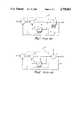
- FIG. 4The modified dual accumulator system is shown in FIG. 4.
- the common features of FIG. 3 and FIG. 4have been identified by identical reference numerals.
- a feed forward line 55is also provided connecting the output of the summer 12 via a one bit delay 56 to the combiner means 52 where the output from the one bit delay 56 is subtractively combined with the output from the multiplier 50.
- the multiplier 50has a multiplier factor of 2.
- the output voltage Vois presented to a variable divider 64 in the feedback loop between a voltage controlled oscillator 62 and a phase detector 60
- the phase detector 60When Vo(z) is presented to the variable 64 divider, the phase detector 60 in effect integrates the components due to Vo(z), such that the components at the output of the phase detectors are: ##EQU5## where K 0 is the phase detector gain.
- a modified dual accumulator systemwhich has superior performance to the known systems. This is achieved by increasing the dynamic range of the second accumulator and feeding it with the differentiated contents of the first accumulator. This results in the interpolation sidebands of the first accumulator appearing in anti-phase in the output bit stream of the second accumulator. When the two bit streams are recombined, all the sidebands due to the first accumulator are automatically cancelled and so do not appear at the synthesiser. A more efficient interpolatng bit stream is thus achieved.
- the present inventiontherefore may be employed to avoid the use of "temporary phase shifts". Greater improvement is achieved by the use of "temporary frequency shifts" which result in complete cancellation of the first accumulator sideband before the sequence is presented to the synthesiser.
- the synthesiserthus receives only the unwanted interpolation sideband generated by the second accumulator and not those from both as with the known system.
- a novel feature of the present inventionis a system whereby the introduction of "temporary frequency shifts" result in the internal cancellation of all unwanted sidebands due to the first accumulator.
Landscapes
- Digital Transmission Methods That Use Modulated Carrier Waves (AREA)
- Stabilization Of Oscillater, Synchronisation, Frequency Synthesizers (AREA)
Abstract
Description
The present invention relates to improvements in synthesisers of the fractional N type and in particular, to improvements for cancelling unwanted sidebands produced in such synthesisers when operating in the fractional N mode.
Frequency synthesisers usually comprise a voltage controlled oscillator (VCO) for providing an output signal and arranged in a phase lock loop. In order to adjust the frequency of the output signal of the synthesiser the output signal of the VCO is fed via a variable divider to a phase detector which provides a control signal to the VCO in the presence of a phase difference between a reference signal from a reference source and the output signal from the variable divider. The output frequency of such synthesisers can, however, only be varied as a multiple of the reference signal frequency and it is usually desirable to vary the output frequency in relatively small increments. If the reference signal frequency is reduced in order to produce sufficiently small increments the settling time of the synthesiser may be increased to an extent such that it is impractical for many applications. It has, therefore, previously been proposed to include additional circuitry in the synthesiser to enable operation in the fractional N mode and such synthesisers are generally known as fractional N synthesisers. In a fractional N synthesizer the division ratio N of the variable divider is controlled in multiples of N such that, over a number of cycles of the reference signal, the mean value of the division ratio, termed N mean, is the desired fraction of the division ratio N.
However, the operation of the synthesiser in the fractional N mode usually gives rise to a ripple signal, which in view of the phase lock loop configuration in the synthesiser, produces frequency modulation of the output signal from the voltage controlled oscillator and hence, the output signal has poor spectral purity.
In order to compensate for the ripple signal it has been proposed to include a phase modulator between the variable divider and phase detector of the phase lock loop. The phase modulator is driven with a drive signal in order to provide compensation of the ripple signal. However, accurate compensation of the ripple signal is heavily dependent on the accurate setting of the level of the drive signal to the phase modulator. Previous attempts to use feedback control to correct the level of the drive signal, and thus to provide optimum compensation of the ripple signal, have relied upon the extraction of a ripple rate signal from the control signal for the voltage controlled oscillator. However, the amplitude of the ripple signal is small compared to the amplitude of the control signal of the VCO and hence, it is difficult to control accurately the level of the drive signal for the phase modulator.
At present most fractional-N synthesisers are interpolated using either a single or a double accumulator scheme to obtain sub-reference rate output frequencies. In both cases the accumulators produce a bit stream which is applied to the variable divider. The integral of the bit stream is applied via a D/A converter to the synthesiser phase detector output. The sidebands produced by the interpolation are therefore cancelled leaving the induced frequency shift intact.
The single accumulator scheme works well so long as good tracking between the cancellation waveform and the ripple at the phase detector output is maintained. This is not easily achieved with variations in temperature, ageing and vibration. Also the initial calibration is extremely difficult due to the high sensitivities involved.
The double accumulator scheme produces a more efficient output bit stream which actually spreads out the unwanted interpolation sidebands. This results in a reduction of sideband amplitude at a rate of 20 dB per decade of interpolation over a single accumulator scheme. It achieves this by running two accumulators in a series/parallel arrangement. The two output bit streams are suitably combined to form another more efficient bit stream. Thus the matching of the cancellation waveform is relaxed by an order of magnitude and the problems associated with good tracking are much reduced.
The double accumulator scheme is a sub optimum system because there are additional sidebands present which produce "temporary phase shifts" within the synthesiser. This reduces the performance possible from such a system.
An objective of the present invention is to provide a modified dual accumulator system in which the unwanted sidebands due to the first accumulator are cancelled. The synthesiser thus receives only the unwanted interpolation sideband generated by the second accumulator and not those from both accumulators as with known systems.
According to the present invention there is provided a fractional N synthesiser comprising a voltage, controlled oscillator for producing an output signal which is afforded to a phase detector via a variable divider to provide a control signal for the voltage controlled oscillator in the presence of a phase difference between a reference sigal from a reference source and the signal afforded thereto from the variable divider wherein the synthesiser is provided with first and second accumulators, the arrangement of the accumulators being such that an output signal from the arrangement is provided in which the interpolation sidebands of the first accumulator caused by quantisation errors in the first accumulator are cancelled, means being provided for setting the division ratio of the variable divider in dependence upon said output signal.
In a preferred embodiment of the present invention the first and second accumulators are arranged so that the second accumulator is fed with the differential contents of the first accumulator, the arrangement causing the interpolation sidebands of the first accumulator to appear in antiphase at the output of the second accumulator.
The invention will be described further, by way of example, with reference to the accompanying drawings in which:
FIG. 1 is a schematic block diagram of a model of a single accumulator system;
FIG. 2 is a schematic block diagram of a noise model of the system of FIG. 1 incorporating a one bit quantiser;
FIG. 3 is a schematic block diagram of a known dual accumulator system; and,
FIG. 4 is a schematic block diagram of a modified dual accumulator system in accordance with one embodiment of the present invention.
Referring to FIG. 1 anaccumulator 2 comprises combiner means 4, which may take the form of an X-bit adder, for receiving a digital input D1. The combiner means 4 is connected to adigital controller 6, the output of which is connected to a one bit quantiser in the form of a digital slicer means 8. Feedback means is provided, in the form of afeedback control loop 10, between the output of theslicer 8 and the combiner means 4. Thedigital controller 6 comprises summing means 12 in combination with a onebit delay 14 in afeedback loop 16.
The output signal Do is presented to the synthesiser's variable divider (not shown) for interpolation.
The contents of the accumulator Vx, are appropriately summed at the synthesiser phase detector output via a D/A converter, for sideband cancellation. FIG. 1 shows the block diagram of the operation of the system. If the digital slicer is represented as a one bit quantiser with an associated quantisation error of Q, then the model can be redrawn as shown in FIG. 2. It is the quantisation error Q, which results in the unwanted sidebands.
From inspection: ##EQU1## Taking the bilinear transform gives: ##EQU2## in which W has a relationship to Z expressed by W=az+b/cz+d where a, b, c and d are constants
The noise sidebands due to Q are actually shaped by a high pass filter characteristic with a slope of 20dB per decade.
The known dual accummulator system is shown in FIG. 3.
Referring to FIG. 3 it will be seen that afirst accumulator 20 takes the same form as the accumulator in FIG. 2 the same reference numerals having been adopoted. Asecond accumulator 22 is also provided comprising a combiner means 24 for receiving the output from thesumming means 12. The combiner means 24 is connected to adigital controller 26, the output of which is connected to a one bit quantiser in the form of adigital slicer 28. Feedback means is provided, in the form of afeedback loop 30, between the output of theslicer 28 and the combiner means 24. Thedigital controller 26 comprises asumming means 32 in combination with a onebit delay 34 in afeedback loop 36. The output from theslicer 28 is fed to a combiner means 38 both directly and via a onebit delay 40, the output from the onebit delay 40 being subtractively combined at the combiner means 38 with the output from the onebit delay 40. The output from the combiner means 38 is fed to a combiner means 42 along aline 39 and combined with the output from thefirst accumalator 20 which is fed to the combiner means 42 along aline 41.
For the dual accumulator analysis shows: ##EQU3##
Here it is seen that the noise components due to Q1 and Q2 are shaped by high pass filter characteristics of 40 dB per decade. This results in an unwanted sideband level improvement of 20 dB per decade over the single accumulator system.
The modified dual accumulator system is shown in FIG. 4. The common features of FIG. 3 and FIG. 4 have been identified by identical reference numerals. Referring to FIG. 4 there is provided amultiplier 50 and a combiner means 52 in aline 54 connecting the output of thesummer 12 to the input of the combiner means 24. A feed forwardline 55 is also provided connecting the output of thesummer 12 via a onebit delay 56 to the combiner means 52 where the output from the onebit delay 56 is subtractively combined with the output from themultiplier 50. Themultiplier 50 has a multiplier factor of 2.
For the modified dual accumulator analysis shows: ##EQU4##
Here it is seen that a 20 dB per decade improvement also results over the first accumulator. However the output sequence Vo(z) is more efficient than the known system because no noise due to Q1 exists in the interpolation bit stream.
As shown in the small insert in FIG. 4 the output voltage Vo is presented to avariable divider 64 in the feedback loop between a voltage controlledoscillator 62 and aphase detector 60
When Vo(z) is presented to the variable 64 divider, thephase detector 60 in effect integrates the components due to Vo(z), such that the components at the output of the phase detectors are: ##EQU5## where K0 is the phase detector gain.
If the contents of the second accumulator are subtracted from the contents of the first then: ##EQU6## which are the unwanted sideband components. If they are differentiated then the term becomes: ##EQU7##
Applying this in antiphase at the output of the phase detector exactly cancels the unwanted sidebands due to interpolation.
In the present invention a modified dual accumulator system is proposed which has superior performance to the known systems. This is achieved by increasing the dynamic range of the second accumulator and feeding it with the differentiated contents of the first accumulator. This results in the interpolation sidebands of the first accumulator appearing in anti-phase in the output bit stream of the second accumulator. When the two bit streams are recombined, all the sidebands due to the first accumulator are automatically cancelled and so do not appear at the synthesiser. A more efficient interpolatng bit stream is thus achieved.
The present invention therefore may be employed to avoid the use of "temporary phase shifts". Greater improvement is achieved by the use of "temporary frequency shifts" which result in complete cancellation of the first accumulator sideband before the sequence is presented to the synthesiser. The synthesiser thus receives only the unwanted interpolation sideband generated by the second accumulator and not those from both as with the known system.
A novel feature of the present invention is a system whereby the introduction of "temporary frequency shifts" result in the internal cancellation of all unwanted sidebands due to the first accumulator.
Although the present invention has been described with respect to a particular embodiment, it should be understood that modifications may be effected within the scope of the invention.
Claims (2)
1. A fractional N synthesiser comprising a voltage controlled oscillator for producing an output signal which is afforded to a phase detector via a variable divider to provide a control signal for the voltage controlled oscillator in the presence of a phase difference between a reference signal from a reference source and the signal afforded thereto from the variable divider, the synthesiser being provided with first and second accumulators, the first and second accumulators each having a combiner means for receiving a digital input, a digital controller the input of which is connected to the output of the combiner means, a digital slicer means the input of which is connected to the output of the digital controller, and feedback means between the output of the digital slicer means and the combiner means, second combiner means being provided for combining the outputs of the first and second accumulators, wherein the improvement lies in the provision of a multiplier the input of which is connected to the output of the digital controller of the first accumulator, a third combiner means connected between the output of the multiplier and the input of the second accumulator, second feedback means connected between the input to the multiplier and the third combiner means and a delay means in the second feedback means, whereby in operation an output signal from the second combiner means is provided in which the interpolation sidebands of the first accumulator caused by quantisation errors in the first accumulator are cancelled, and means being provided for setting the division ratio of the variable divider in dependence upon said output signal from the second combiner means.
2. A fractional N synthesiser as claimed in claim 1 wherein the output of the delay means is subtractively combined at the third combiner means with the output of the multiplier, the multiplier and the bit delay of the delay means being arranged so that the second accumulator is fed with the differential contents of the first accumulator, the interpolation sidebands of the first accumulator appearing in antiphase at the output of the second accumulator.
Applications Claiming Priority (2)
| Application Number | Priority Date | Filing Date | Title |
|---|---|---|---|
| GB8504543 | 1985-02-21 | ||
| GB8504543 | 1985-02-21 |
Publications (1)
| Publication Number | Publication Date |
|---|---|
| US4758802Atrue US4758802A (en) | 1988-07-19 |
Family
ID=10574890
Family Applications (1)
| Application Number | Title | Priority Date | Filing Date |
|---|---|---|---|
| US06/925,631Expired - Fee RelatedUS4758802A (en) | 1985-02-21 | 1986-02-21 | Fractional N synthesizer |
Country Status (5)
| Country | Link |
|---|---|
| US (1) | US4758802A (en) |
| EP (1) | EP0211921A1 (en) |
| JP (1) | JPS62502232A (en) |
| GB (1) | GB2172760B (en) |
| WO (1) | WO1986005046A1 (en) |
Cited By (39)
| Publication number | Priority date | Publication date | Assignee | Title |
|---|---|---|---|---|
| US4918403A (en)* | 1988-06-03 | 1990-04-17 | Motorola, Inc. | Frequency synthesizer with spur compensation |
| US5038117A (en)* | 1990-01-23 | 1991-08-06 | Hewlett-Packard Company | Multiple-modulator fractional-N divider |
| US5055802A (en)* | 1990-04-30 | 1991-10-08 | Motorola, Inc. | Multiaccumulator sigma-delta fractional-n synthesis |
| US5055800A (en)* | 1990-04-30 | 1991-10-08 | Motorola, Inc. | Fractional n/m synthesis |
| US5065408A (en)* | 1990-04-26 | 1991-11-12 | Motorola, Inc. | Fractional-division synthesizer for a voice/data communications systems |
| US5070310A (en)* | 1990-08-31 | 1991-12-03 | Motorola, Inc. | Multiple latched accumulator fractional N synthesis |
| US5093632A (en)* | 1990-08-31 | 1992-03-03 | Motorola, Inc. | Latched accumulator fractional n synthesis with residual error reduction |
| US5124670A (en)* | 1989-03-31 | 1992-06-23 | Lawton Rodney J | Frequency synthesizers with fractional division |
| US5305362A (en)* | 1992-12-10 | 1994-04-19 | Hewlett-Packard Company | Spur reduction for multiple modulator based synthesis |
| US5495505A (en)* | 1990-12-20 | 1996-02-27 | Motorola, Inc. | Increased frequency resolution in a synthesizer |
| US5495206A (en)* | 1993-10-29 | 1996-02-27 | Motorola, Inc. | Fractional N frequency synthesis with residual error correction and method thereof |
| US6137372A (en)* | 1998-05-29 | 2000-10-24 | Silicon Laboratories Inc. | Method and apparatus for providing coarse and fine tuning control for synthesizing high-frequency signals for wireless communications |
| US6147567A (en)* | 1998-05-29 | 2000-11-14 | Silicon Laboratories Inc. | Method and apparatus for providing analog and digitally controlled capacitances for synthesizing high-frequency signals for wireless communications |
| US6150891A (en)* | 1998-05-29 | 2000-11-21 | Silicon Laboratories, Inc. | PLL synthesizer having phase shifted control signals |
| DE19937608A1 (en)* | 1999-08-09 | 2001-02-15 | Rohde & Schwarz | Frequency synthesizer |
| US6226506B1 (en) | 1998-05-29 | 2001-05-01 | Silicon Laboratories, Inc. | Method and apparatus for eliminating floating voltage nodes within a discreetly variable capacitance used for synthesizing high-frequency signals for wireless communications |
| US6233441B1 (en) | 1998-05-29 | 2001-05-15 | Silicon Laboratories, Inc. | Method and apparatus for generating a discretely variable capacitance for synthesizing high-frequency signals for wireless communications |
| US6304146B1 (en) | 1998-05-29 | 2001-10-16 | Silicon Laboratories, Inc. | Method and apparatus for synthesizing dual band high-frequency signals for wireless communications |
| US6308055B1 (en) | 1998-05-29 | 2001-10-23 | Silicon Laboratories, Inc. | Method and apparatus for operating a PLL for synthesizing high-frequency signals for wireless communications |
| US6311050B1 (en) | 1998-05-29 | 2001-10-30 | Silicon Laboratories, Inc. | Single integrated circuit phase locked loop for synthesizing high-frequency signals for wireless communications and method for operating same |
| US6323735B1 (en) | 2000-05-25 | 2001-11-27 | Silicon Laboratories, Inc. | Method and apparatus for synthesizing high-frequency signals utilizing on-package oscillator circuit inductors |
| US6327463B1 (en) | 1998-05-29 | 2001-12-04 | Silicon Laboratories, Inc. | Method and apparatus for generating a variable capacitance for synthesizing high-frequency signals for wireless communications |
| US20020187763A1 (en)* | 1998-05-29 | 2002-12-12 | Lysander Lim | Apparatus and methods for generating radio frequencies in communication circuitry |
| US6529716B1 (en) | 2000-01-11 | 2003-03-04 | Skyworks Solutions, Inc. | RF transmitter with extended efficient power control range |
| US6574288B1 (en) | 1998-05-29 | 2003-06-03 | Silicon Laboratories Inc. | Method and apparatus for adjusting a digital control word to tune synthesized high-frequency signals for wireless communications |
| US6681101B1 (en) | 2000-01-11 | 2004-01-20 | Skyworks Solutions, Inc. | RF transmitter with extended efficient power control range |
| US6693468B2 (en)* | 2001-06-12 | 2004-02-17 | Rf Micro Devices, Inc. | Fractional-N synthesizer with improved noise performance |
| US20040077327A1 (en)* | 1998-05-29 | 2004-04-22 | Lysander Lim | Frequency modification circuitry for use in radio-frequency communication apparatus and associated methods |
| US20040075506A1 (en)* | 1998-05-29 | 2004-04-22 | Silicon Laboratories Inc. | Method and apparatus for operating a PLL with a phase detector/sample hold circuit for synthesizing high-frequency signals for wireless communications |
| US20040166815A1 (en)* | 1998-05-29 | 2004-08-26 | James Maligeorgos | Partitioning of radio-frequency apparatus |
| US20040165691A1 (en)* | 2003-02-25 | 2004-08-26 | Rana Ram Singh | Fractional-N synthesizer with two control words |
| US6993314B2 (en) | 1998-05-29 | 2006-01-31 | Silicon Laboratories Inc. | Apparatus for generating multiple radio frequencies in communication circuitry and associated methods |
| US7024171B2 (en) | 2003-02-25 | 2006-04-04 | Icom America, Incorporated | Fractional-N frequency synthesizer with cascaded sigma-delta converters |
| US20060246858A1 (en)* | 2005-04-27 | 2006-11-02 | Boerman Steven P | Switchable power level detector for multi-mode communication device |
| US20070054629A1 (en)* | 1998-05-29 | 2007-03-08 | Silicon Laboratories Inc. | Partitioning of radio-frequency apparatus |
| US20080164917A1 (en)* | 2007-01-10 | 2008-07-10 | Floyd Brian A | Circuits and methods for implementing sub-integer-n frequency dividers using phase rotators |
| US20080166984A1 (en)* | 2007-01-09 | 2008-07-10 | Terrence John Shie | Multiband or multimode receiver with shared bias circuit |
| US20090115520A1 (en)* | 2006-12-04 | 2009-05-07 | Ripley David S | Temperature compensation of collector-voltage control RF amplifiers |
| WO2014078311A3 (en)* | 2012-11-14 | 2014-08-21 | Adeptence, Llc | Frequency synthesis using a phase locked loop |
Families Citing this family (13)
| Publication number | Priority date | Publication date | Assignee | Title |
|---|---|---|---|---|
| US4816774A (en)* | 1988-06-03 | 1989-03-28 | Motorola, Inc. | Frequency synthesizer with spur compensation |
| DE3826006C1 (en)* | 1988-07-30 | 1989-10-12 | Wandel & Goltermann Gmbh & Co, 7412 Eningen, De | |
| CA2003428C (en)* | 1989-11-21 | 1999-12-14 | Thomas Atkin Denning Riley | Frequency synthesizer |
| CA2019297A1 (en)* | 1990-01-23 | 1991-07-23 | Brian M. Miller | Multiple-modulator fractional-n divider |
| US6011815A (en)* | 1997-09-16 | 2000-01-04 | Telefonaktiebolaget Lm Ericsson | Compensated ΔΣ controlled phase locked loop modulator |
| US6047029A (en)* | 1997-09-16 | 2000-04-04 | Telefonaktiebolaget Lm Ericsson | Post-filtered delta sigma for controlling a phase locked loop modulator |
| RU2227366C2 (en)* | 2002-05-06 | 2004-04-20 | Марийский государственный технический университет | Digital frequency synthesizer having extended frequency range |
| RU2223597C1 (en)* | 2002-06-21 | 2004-02-10 | Федеральное государственное унитарное предприятие Научно-производственное предприятие "Полет" | Digital frequency synthesizer |
| RU2250560C1 (en)* | 2003-07-14 | 2005-04-20 | Федеральное государственное унитарное предприятие "Рязанское конструкторское бюро "Глобус" | Digital signal synthesizer |
| RU2294054C1 (en)* | 2005-10-25 | 2007-02-20 | Государственное образовательное учреждение высшего профессионального образования Марийский государственный технический университет | Digital quadrature-output computing synthesizer |
| RU2341892C2 (en)* | 2006-12-21 | 2008-12-20 | ФГУП Центральный научно-исследовательский институт связи (ФГУП ЦНИИС) | Time-and-frequency synchronisation device |
| US8653869B2 (en) | 2011-10-20 | 2014-02-18 | Media Tek Singapore Pte. Ltd. | Segmented fractional-N PLL |
| RU2692965C1 (en)* | 2018-06-18 | 2019-06-28 | Федеральное государственное бюджетное учреждение науки Институт автоматики и электрометрии Сибирского отделения Российской академии наук (ИАиЭ СО РАН) | Quadrature signals phase recording method |
Citations (3)
| Publication number | Priority date | Publication date | Assignee | Title |
|---|---|---|---|---|
| GB2026268A (en)* | 1978-07-22 | 1980-01-30 | Racal Communcations Equipment | Frequency synthesizers |
| US4223389A (en)* | 1977-06-03 | 1980-09-16 | Hitachi, Ltd. | Recursive digital filter having means to prevent overflow oscillation |
| EP0125790B1 (en)* | 1983-05-17 | 1989-06-21 | Marconi Instruments Limited | Frequency synthesisers |
- 1986
- 1986-02-21EPEP86901443Apatent/EP0211921A1/ennot_activeWithdrawn
- 1986-02-21JPJP61501274Apatent/JPS62502232A/enactivePending
- 1986-02-21WOPCT/GB1986/000092patent/WO1986005046A1/ennot_activeApplication Discontinuation
- 1986-02-21GBGB08604338Apatent/GB2172760B/ennot_activeExpired
- 1986-02-21USUS06/925,631patent/US4758802A/ennot_activeExpired - Fee Related
Patent Citations (3)
| Publication number | Priority date | Publication date | Assignee | Title |
|---|---|---|---|---|
| US4223389A (en)* | 1977-06-03 | 1980-09-16 | Hitachi, Ltd. | Recursive digital filter having means to prevent overflow oscillation |
| GB2026268A (en)* | 1978-07-22 | 1980-01-30 | Racal Communcations Equipment | Frequency synthesizers |
| EP0125790B1 (en)* | 1983-05-17 | 1989-06-21 | Marconi Instruments Limited | Frequency synthesisers |
Cited By (71)
| Publication number | Priority date | Publication date | Assignee | Title |
|---|---|---|---|---|
| US4918403A (en)* | 1988-06-03 | 1990-04-17 | Motorola, Inc. | Frequency synthesizer with spur compensation |
| US5124670A (en)* | 1989-03-31 | 1992-06-23 | Lawton Rodney J | Frequency synthesizers with fractional division |
| US5038117A (en)* | 1990-01-23 | 1991-08-06 | Hewlett-Packard Company | Multiple-modulator fractional-N divider |
| US5065408A (en)* | 1990-04-26 | 1991-11-12 | Motorola, Inc. | Fractional-division synthesizer for a voice/data communications systems |
| US5055802A (en)* | 1990-04-30 | 1991-10-08 | Motorola, Inc. | Multiaccumulator sigma-delta fractional-n synthesis |
| US5055800A (en)* | 1990-04-30 | 1991-10-08 | Motorola, Inc. | Fractional n/m synthesis |
| AU646304B2 (en)* | 1990-08-31 | 1994-02-17 | Motorola, Inc. | Latched accumulator fractional N synthesizer |
| DE4192081C2 (en)* | 1990-08-31 | 1996-02-01 | Motorola Inc | Device for frequency synthesis using non-integer frequency division ratios |
| US5093632A (en)* | 1990-08-31 | 1992-03-03 | Motorola, Inc. | Latched accumulator fractional n synthesis with residual error reduction |
| GB2253752A (en)* | 1990-08-31 | 1992-09-16 | Motorola Inc | Latched accumulator fractional n synthesis with residual error reduction |
| US5070310A (en)* | 1990-08-31 | 1991-12-03 | Motorola, Inc. | Multiple latched accumulator fractional N synthesis |
| JP2844389B2 (en) | 1990-08-31 | 1999-01-06 | モトローラ・インコーポレーテッド | Synthesis of multistage latch accumulator fraction N |
| GB2253752B (en)* | 1990-08-31 | 1994-11-23 | Motorola Inc | Latched accumulator fractional-n synthesis with reduced residual error |
| WO1992004767A1 (en)* | 1990-08-31 | 1992-03-19 | Motorola, Inc. | Latched accumulator fractional n synthesis with residual error reduction |
| DE4192071C2 (en)* | 1990-08-31 | 1996-02-22 | Motorola Inc | Device for frequency synthesis using non-integer frequency division ratios |
| JP2750639B2 (en) | 1990-08-31 | 1998-05-13 | モトローラ・インコーポレーテッド | Latch accumulator fractional N synthesis with residual error reduction |
| AT402246B (en)* | 1990-08-31 | 1997-03-25 | Motorola Inc | BREAKAGE-N-SYNTHESIS WITH LOCKED STORAGE WORKS AND WITH REDUCTION OF THE RESIDUAL ERROR |
| ES2088715A1 (en)* | 1990-08-31 | 1996-08-16 | Motorola Inc | FRACTIONAL-N SYNTHESIS OF ENGAGED ACCUMULATORS WITH REDUCTION OF RESIDUAL ERROR. |
| US5495505A (en)* | 1990-12-20 | 1996-02-27 | Motorola, Inc. | Increased frequency resolution in a synthesizer |
| US5305362A (en)* | 1992-12-10 | 1994-04-19 | Hewlett-Packard Company | Spur reduction for multiple modulator based synthesis |
| US5495206A (en)* | 1993-10-29 | 1996-02-27 | Motorola, Inc. | Fractional N frequency synthesis with residual error correction and method thereof |
| US6483390B2 (en) | 1998-05-29 | 2002-11-19 | Silicon Laboratories Inc. | Method and apparatus for synthesizing dual band high-frequency signals for wireless communications |
| US20040166815A1 (en)* | 1998-05-29 | 2004-08-26 | James Maligeorgos | Partitioning of radio-frequency apparatus |
| US6150891A (en)* | 1998-05-29 | 2000-11-21 | Silicon Laboratories, Inc. | PLL synthesizer having phase shifted control signals |
| US7353011B2 (en) | 1998-05-29 | 2008-04-01 | Silicon Laboratories Inc. | Method and apparatus for operating a PLL for synthesizing high-frequency signals for wireless communications |
| US6226506B1 (en) | 1998-05-29 | 2001-05-01 | Silicon Laboratories, Inc. | Method and apparatus for eliminating floating voltage nodes within a discreetly variable capacitance used for synthesizing high-frequency signals for wireless communications |
| US6233441B1 (en) | 1998-05-29 | 2001-05-15 | Silicon Laboratories, Inc. | Method and apparatus for generating a discretely variable capacitance for synthesizing high-frequency signals for wireless communications |
| US6304146B1 (en) | 1998-05-29 | 2001-10-16 | Silicon Laboratories, Inc. | Method and apparatus for synthesizing dual band high-frequency signals for wireless communications |
| US6308055B1 (en) | 1998-05-29 | 2001-10-23 | Silicon Laboratories, Inc. | Method and apparatus for operating a PLL for synthesizing high-frequency signals for wireless communications |
| US6311050B1 (en) | 1998-05-29 | 2001-10-30 | Silicon Laboratories, Inc. | Single integrated circuit phase locked loop for synthesizing high-frequency signals for wireless communications and method for operating same |
| US6317006B1 (en) | 1998-05-29 | 2001-11-13 | Silicon Laboratories, Inc. | Frequency synthesizer utilizing phase shifted control signals |
| US7242912B2 (en) | 1998-05-29 | 2007-07-10 | Silicon Laboratories Inc. | Partitioning of radio-frequency apparatus |
| US6327463B1 (en) | 1998-05-29 | 2001-12-04 | Silicon Laboratories, Inc. | Method and apparatus for generating a variable capacitance for synthesizing high-frequency signals for wireless communications |
| US6388536B1 (en) | 1998-05-29 | 2002-05-14 | Silicon Laboratories Inc. | Method and apparatus for providing coarse and fine tuning control for synthesizing high-frequency signals for wireless communications |
| US6137372A (en)* | 1998-05-29 | 2000-10-24 | Silicon Laboratories Inc. | Method and apparatus for providing coarse and fine tuning control for synthesizing high-frequency signals for wireless communications |
| US20020187763A1 (en)* | 1998-05-29 | 2002-12-12 | Lysander Lim | Apparatus and methods for generating radio frequencies in communication circuitry |
| US7221921B2 (en) | 1998-05-29 | 2007-05-22 | Silicon Laboratories | Partitioning of radio-frequency apparatus |
| US6549764B2 (en) | 1998-05-29 | 2003-04-15 | Silicon Laboratories Inc. | Method and apparatus for selecting capacitance amounts to vary the output frequency of a controlled oscillator |
| US6549765B2 (en) | 1998-05-29 | 2003-04-15 | Silicon Laboratories, Inc. | Phase locked loop circuitry for synthesizing high-frequency signals and associated method |
| US6574288B1 (en) | 1998-05-29 | 2003-06-03 | Silicon Laboratories Inc. | Method and apparatus for adjusting a digital control word to tune synthesized high-frequency signals for wireless communications |
| US20030119467A1 (en)* | 1998-05-29 | 2003-06-26 | Silicon Laboratories, Inc. | Method and apparatus for operating a PLL for synthesizing high-frequency signals for wireless communications |
| US7200364B2 (en) | 1998-05-29 | 2007-04-03 | Silicon Laboratories | Frequency modification circuitry for use in radio-frequency communication apparatus and associated methods |
| US20070054629A1 (en)* | 1998-05-29 | 2007-03-08 | Silicon Laboratories Inc. | Partitioning of radio-frequency apparatus |
| US20040077327A1 (en)* | 1998-05-29 | 2004-04-22 | Lysander Lim | Frequency modification circuitry for use in radio-frequency communication apparatus and associated methods |
| US20040075506A1 (en)* | 1998-05-29 | 2004-04-22 | Silicon Laboratories Inc. | Method and apparatus for operating a PLL with a phase detector/sample hold circuit for synthesizing high-frequency signals for wireless communications |
| US6760575B2 (en) | 1998-05-29 | 2004-07-06 | Silicon Laboratories, Inc. | Method and apparatus for generating a variable capacitance for synthesizing high-frequency signals for wireless communications |
| US6147567A (en)* | 1998-05-29 | 2000-11-14 | Silicon Laboratories Inc. | Method and apparatus for providing analog and digitally controlled capacitances for synthesizing high-frequency signals for wireless communications |
| US7092675B2 (en) | 1998-05-29 | 2006-08-15 | Silicon Laboratories | Apparatus and methods for generating radio frequencies in communication circuitry using multiple control signals |
| US20060160512A1 (en)* | 1998-05-29 | 2006-07-20 | Silicon Laboratories Inc. | Frequency modification circuitry for use in radio-frequency communication apparatus and associated methods |
| US6965761B2 (en) | 1998-05-29 | 2005-11-15 | Silicon Laboratories, Inc. | Controlled oscillator circuitry for synthesizing high-frequency signals and associated method |
| US20050266817A1 (en)* | 1998-05-29 | 2005-12-01 | Silicon Laboratories, Inc. | Method and apparatus for operating a PLL for synthesizing high-frequency signals for wireless communications |
| US6993314B2 (en) | 1998-05-29 | 2006-01-31 | Silicon Laboratories Inc. | Apparatus for generating multiple radio frequencies in communication circuitry and associated methods |
| US6993307B2 (en) | 1998-05-29 | 2006-01-31 | Silicon Laboratories, Inc. | Method and apparatus for operating a PLL with a phase detector/sample hold circuit for synthesizing high-frequency signals for wireless communications |
| US7035607B2 (en) | 1998-05-29 | 2006-04-25 | Silicon Laboratories Inc. | Systems and methods for providing an adjustable reference signal to RF circuitry |
| DE19937608A1 (en)* | 1999-08-09 | 2001-02-15 | Rohde & Schwarz | Frequency synthesizer |
| US6681101B1 (en) | 2000-01-11 | 2004-01-20 | Skyworks Solutions, Inc. | RF transmitter with extended efficient power control range |
| US6529716B1 (en) | 2000-01-11 | 2003-03-04 | Skyworks Solutions, Inc. | RF transmitter with extended efficient power control range |
| US6323735B1 (en) | 2000-05-25 | 2001-11-27 | Silicon Laboratories, Inc. | Method and apparatus for synthesizing high-frequency signals utilizing on-package oscillator circuit inductors |
| US6693468B2 (en)* | 2001-06-12 | 2004-02-17 | Rf Micro Devices, Inc. | Fractional-N synthesizer with improved noise performance |
| US7024171B2 (en) | 2003-02-25 | 2006-04-04 | Icom America, Incorporated | Fractional-N frequency synthesizer with cascaded sigma-delta converters |
| US20040165691A1 (en)* | 2003-02-25 | 2004-08-26 | Rana Ram Singh | Fractional-N synthesizer with two control words |
| US6836526B2 (en) | 2003-02-25 | 2004-12-28 | Agency For Science, Technology And Research | Fractional-N synthesizer with two control words |
| US20060246858A1 (en)* | 2005-04-27 | 2006-11-02 | Boerman Steven P | Switchable power level detector for multi-mode communication device |
| US7493093B2 (en) | 2005-04-27 | 2009-02-17 | Skyworks Solutions, Inc. | Switchable power level detector for multi-mode communication device |
| US20090115520A1 (en)* | 2006-12-04 | 2009-05-07 | Ripley David S | Temperature compensation of collector-voltage control RF amplifiers |
| US7696826B2 (en) | 2006-12-04 | 2010-04-13 | Skyworks Solutions, Inc. | Temperature compensation of collector-voltage control RF amplifiers |
| US20080166984A1 (en)* | 2007-01-09 | 2008-07-10 | Terrence John Shie | Multiband or multimode receiver with shared bias circuit |
| US7729674B2 (en) | 2007-01-09 | 2010-06-01 | Skyworks Solutions, Inc. | Multiband or multimode receiver with shared bias circuit |
| US20080164917A1 (en)* | 2007-01-10 | 2008-07-10 | Floyd Brian A | Circuits and methods for implementing sub-integer-n frequency dividers using phase rotators |
| US7486145B2 (en) | 2007-01-10 | 2009-02-03 | International Business Machines Corporation | Circuits and methods for implementing sub-integer-N frequency dividers using phase rotators |
| WO2014078311A3 (en)* | 2012-11-14 | 2014-08-21 | Adeptence, Llc | Frequency synthesis using a phase locked loop |
Also Published As
| Publication number | Publication date |
|---|---|
| GB8604338D0 (en) | 1986-03-26 |
| JPS62502232A (en) | 1987-08-27 |
| GB2172760A (en) | 1986-09-24 |
| EP0211921A1 (en) | 1987-03-04 |
| WO1986005046A1 (en) | 1986-08-28 |
| GB2172760B (en) | 1988-05-18 |
Similar Documents
| Publication | Publication Date | Title |
|---|---|---|
| US4758802A (en) | Fractional N synthesizer | |
| US4800342A (en) | Frequency synthesizer of the fractional type | |
| US4686488A (en) | Fractional N frequency synthesizer with modulation compensation | |
| US5821816A (en) | Integer division variable frequency synthesis apparatus and method | |
| US4888564A (en) | Phase-locked loop circuit | |
| US5038120A (en) | Frequency modulated phase locked loop with fractional divider and jitter compensation | |
| EP0325025B1 (en) | Frequency modulation in phase-locked loop | |
| US5124670A (en) | Frequency synthesizers with fractional division | |
| US5847611A (en) | Fractional divided frequency synthesizer with phase error compensating circuit | |
| US4458329A (en) | Frequency synthesizer including a fractional multiplier | |
| US4024464A (en) | Frequency synthesizer of the phase lock loop type | |
| JP2962554B2 (en) | Frequency or phase modulator | |
| US5126699A (en) | Digitally compensated modulation system for frequency synthesizers | |
| EP0622904B1 (en) | PLL circuit having a multiloop, and FM receiving method and apparatus able to utilize the same | |
| EP0557799B1 (en) | Digital error corrected fractional-N synthesizer | |
| US4942374A (en) | Phase-locked loop type synthesizer having modulation function | |
| US4185247A (en) | Means for reducing spurious frequencies in a direct frequency synthesizer | |
| US4290028A (en) | High speed phase locked loop frequency synthesizer | |
| US4468632A (en) | Phase locked loop frequency synthesizer including fractional digital frequency divider | |
| US5521534A (en) | Numerically controlled oscillator for generating a digitally represented sine wave output signal | |
| US4464638A (en) | Universal digital frequency synthesizer using single side band techniques | |
| US4682122A (en) | Frequency synthesizer stage adding high frequency steps to an initial frequency | |
| US4831339A (en) | Oscillator having low phase noise | |
| JPH07143000A (en) | Synchronous clock production method using controllable oscillator circuit | |
| KR960002669B1 (en) | Frequency synthesizer |
Legal Events
| Date | Code | Title | Description |
|---|---|---|---|
| AS | Assignment | Owner name:PLESSEY OVERSEAS LIMITED, VICARAGE LANE, ILFORD, E Free format text:ASSIGNMENT OF ASSIGNORS INTEREST.;ASSIGNOR:JACKSON, THOMAS;REEL/FRAME:004671/0863 Effective date:19861107 Owner name:PLESSEY OVERSEAS LIMITED,ENGLAND Free format text:ASSIGNMENT OF ASSIGNORS INTEREST;ASSIGNOR:JACKSON, THOMAS;REEL/FRAME:004671/0863 Effective date:19861107 | |
| AS | Assignment | Owner name:SIEMENS PLESSEY ELECTRONIC SYSTEMS LIMITED, ENGLAN Free format text:ASSIGNMENT OF ASSIGNORS INTEREST.;ASSIGNOR:PLESSEY OVERSEAS LIMITED;REEL/FRAME:005454/0528 Effective date:19900717 | |
| FPAY | Fee payment | Year of fee payment:4 | |
| REMI | Maintenance fee reminder mailed | ||
| LAPS | Lapse for failure to pay maintenance fees | ||
| FP | Lapsed due to failure to pay maintenance fee | Effective date:19960724 | |
| STCH | Information on status: patent discontinuation | Free format text:PATENT EXPIRED DUE TO NONPAYMENT OF MAINTENANCE FEES UNDER 37 CFR 1.362 |