US4758228A - Medical infusion pump with sensors - Google Patents
Medical infusion pump with sensorsDownload PDFInfo
- Publication number
- US4758228A US4758228AUS06/931,506US93150686AUS4758228AUS 4758228 AUS4758228 AUS 4758228AUS 93150686 AUS93150686 AUS 93150686AUS 4758228 AUS4758228 AUS 4758228A
- Authority
- US
- United States
- Prior art keywords
- cassette
- wheel
- tubing
- infusion pump
- pump
- Prior art date
- Legal status (The legal status is an assumption and is not a legal conclusion. Google has not performed a legal analysis and makes no representation as to the accuracy of the status listed.)
- Expired - Fee Related
Links
- 238000001802infusionMethods0.000titleclaimsabstractdescription29
- 239000012530fluidSubstances0.000claimsabstractdescription48
- 210000003813thumbAnatomy0.000claimsabstractdescription11
- 230000033001locomotionEffects0.000claimsabstractdescription10
- 230000005355Hall effectEffects0.000claimsabstractdescription9
- 230000009471actionEffects0.000claimsabstractdescription7
- XUIMIQQOPSSXEZ-UHFFFAOYSA-NSiliconChemical compound[Si]XUIMIQQOPSSXEZ-UHFFFAOYSA-N0.000claimsdescription6
- 229910052710siliconInorganic materials0.000claimsdescription6
- 239000010703siliconSubstances0.000claimsdescription6
- 230000002572peristaltic effectEffects0.000claimsdescription5
- 230000008859changeEffects0.000claimsdescription2
- 230000002093peripheral effectEffects0.000claims2
- 238000007599dischargingMethods0.000claims1
- 238000005086pumpingMethods0.000abstractdescription18
- 239000012528membraneSubstances0.000description5
- 229920002799BoPETPolymers0.000description4
- 239000005041Mylar™Substances0.000description4
- 239000008280bloodSubstances0.000description3
- 210000004369bloodAnatomy0.000description3
- 230000006835compressionEffects0.000description3
- 238000007906compressionMethods0.000description3
- 230000009977dual effectEffects0.000description3
- 238000005259measurementMethods0.000description3
- 230000000712assemblyEffects0.000description2
- 238000000429assemblyMethods0.000description2
- 230000008901benefitEffects0.000description2
- 230000005540biological transmissionEffects0.000description2
- 230000005779cell damageEffects0.000description2
- 208000037887cell injuryDiseases0.000description2
- 238000006073displacement reactionMethods0.000description2
- 229920001971elastomerPolymers0.000description2
- 210000003414extremityAnatomy0.000description2
- 238000003780insertionMethods0.000description2
- 230000037431insertionEffects0.000description2
- 230000013011matingEffects0.000description2
- 229920002379silicone rubberPolymers0.000description2
- 238000004901spallingMethods0.000description2
- 229910001369BrassInorganic materials0.000description1
- 239000000853adhesiveSubstances0.000description1
- 230000001070adhesive effectEffects0.000description1
- 210000000988bone and boneAnatomy0.000description1
- 239000010951brassSubstances0.000description1
- 238000010276constructionMethods0.000description1
- 238000011109contaminationMethods0.000description1
- 230000000994depressogenic effectEffects0.000description1
- 230000000694effectsEffects0.000description1
- 230000005484gravityEffects0.000description1
- 238000009434installationMethods0.000description1
- 238000001990intravenous administrationMethods0.000description1
- 230000007257malfunctionEffects0.000description1
- 238000004519manufacturing processMethods0.000description1
- 239000000463materialSubstances0.000description1
- 239000002184metalSubstances0.000description1
- 238000000034methodMethods0.000description1
- 239000002245particleSubstances0.000description1
- 239000013641positive controlSubstances0.000description1
- 238000002360preparation methodMethods0.000description1
- 238000010926purgeMethods0.000description1
- 230000009467reductionEffects0.000description1
- 230000004044responseEffects0.000description1
- 125000006850spacer groupChemical group0.000description1
- 238000012546transferMethods0.000description1
Images


Classifications
- A—HUMAN NECESSITIES
- A61—MEDICAL OR VETERINARY SCIENCE; HYGIENE
- A61M—DEVICES FOR INTRODUCING MEDIA INTO, OR ONTO, THE BODY; DEVICES FOR TRANSDUCING BODY MEDIA OR FOR TAKING MEDIA FROM THE BODY; DEVICES FOR PRODUCING OR ENDING SLEEP OR STUPOR
- A61M5/00—Devices for bringing media into the body in a subcutaneous, intra-vascular or intramuscular way; Accessories therefor, e.g. filling or cleaning devices, arm-rests
- A61M5/14—Infusion devices, e.g. infusing by gravity; Blood infusion; Accessories therefor
- A61M5/142—Pressure infusion, e.g. using pumps
- A61M5/14212—Pumping with an aspiration and an expulsion action
- A61M5/14232—Roller pumps
- A—HUMAN NECESSITIES
- A61—MEDICAL OR VETERINARY SCIENCE; HYGIENE
- A61M—DEVICES FOR INTRODUCING MEDIA INTO, OR ONTO, THE BODY; DEVICES FOR TRANSDUCING BODY MEDIA OR FOR TAKING MEDIA FROM THE BODY; DEVICES FOR PRODUCING OR ENDING SLEEP OR STUPOR
- A61M5/00—Devices for bringing media into the body in a subcutaneous, intra-vascular or intramuscular way; Accessories therefor, e.g. filling or cleaning devices, arm-rests
- A61M5/14—Infusion devices, e.g. infusing by gravity; Blood infusion; Accessories therefor
- A61M5/142—Pressure infusion, e.g. using pumps
- A—HUMAN NECESSITIES
- A61—MEDICAL OR VETERINARY SCIENCE; HYGIENE
- A61M—DEVICES FOR INTRODUCING MEDIA INTO, OR ONTO, THE BODY; DEVICES FOR TRANSDUCING BODY MEDIA OR FOR TAKING MEDIA FROM THE BODY; DEVICES FOR PRODUCING OR ENDING SLEEP OR STUPOR
- A61M5/00—Devices for bringing media into the body in a subcutaneous, intra-vascular or intramuscular way; Accessories therefor, e.g. filling or cleaning devices, arm-rests
- A61M5/14—Infusion devices, e.g. infusing by gravity; Blood infusion; Accessories therefor
- A61M5/168—Means for controlling media flow to the body or for metering media to the body, e.g. drip meters, counters ; Monitoring media flow to the body
- A61M5/16831—Monitoring, detecting, signalling or eliminating infusion flow anomalies
- A61M5/16854—Monitoring, detecting, signalling or eliminating infusion flow anomalies by monitoring line pressure
- A—HUMAN NECESSITIES
- A61—MEDICAL OR VETERINARY SCIENCE; HYGIENE
- A61M—DEVICES FOR INTRODUCING MEDIA INTO, OR ONTO, THE BODY; DEVICES FOR TRANSDUCING BODY MEDIA OR FOR TAKING MEDIA FROM THE BODY; DEVICES FOR PRODUCING OR ENDING SLEEP OR STUPOR
- A61M5/00—Devices for bringing media into the body in a subcutaneous, intra-vascular or intramuscular way; Accessories therefor, e.g. filling or cleaning devices, arm-rests
- A61M5/36—Devices for bringing media into the body in a subcutaneous, intra-vascular or intramuscular way; Accessories therefor, e.g. filling or cleaning devices, arm-rests with means for eliminating or preventing injection or infusion of air into body
- A61M5/365—Air detectors
- A—HUMAN NECESSITIES
- A61—MEDICAL OR VETERINARY SCIENCE; HYGIENE
- A61M—DEVICES FOR INTRODUCING MEDIA INTO, OR ONTO, THE BODY; DEVICES FOR TRANSDUCING BODY MEDIA OR FOR TAKING MEDIA FROM THE BODY; DEVICES FOR PRODUCING OR ENDING SLEEP OR STUPOR
- A61M2205/00—General characteristics of the apparatus
- A61M2205/33—Controlling, regulating or measuring
- A61M2205/3317—Electromagnetic, inductive or dielectric measuring means
- A—HUMAN NECESSITIES
- A61—MEDICAL OR VETERINARY SCIENCE; HYGIENE
- A61M—DEVICES FOR INTRODUCING MEDIA INTO, OR ONTO, THE BODY; DEVICES FOR TRANSDUCING BODY MEDIA OR FOR TAKING MEDIA FROM THE BODY; DEVICES FOR PRODUCING OR ENDING SLEEP OR STUPOR
- A61M2205/00—General characteristics of the apparatus
- A61M2205/33—Controlling, regulating or measuring
- A61M2205/3375—Acoustical, e.g. ultrasonic, measuring means
- Y—GENERAL TAGGING OF NEW TECHNOLOGICAL DEVELOPMENTS; GENERAL TAGGING OF CROSS-SECTIONAL TECHNOLOGIES SPANNING OVER SEVERAL SECTIONS OF THE IPC; TECHNICAL SUBJECTS COVERED BY FORMER USPC CROSS-REFERENCE ART COLLECTIONS [XRACs] AND DIGESTS
- Y10—TECHNICAL SUBJECTS COVERED BY FORMER USPC
- Y10S—TECHNICAL SUBJECTS COVERED BY FORMER USPC CROSS-REFERENCE ART COLLECTIONS [XRACs] AND DIGESTS
- Y10S128/00—Surgery
- Y10S128/12—Pressure infusion
Definitions
- the present inventionrelates generally to fluid infusion systems, and more particularly to an improved medical infusion pump including several flow sensing devices.
- the infusion of fluids into the human bodyis usually accomplished by means of an administration set in conjunction with a metering device which controls the rate of flow of fluid through the set.
- Peristaltic-type pumpswhich function by repetitively compressing and expanding a section of tubing, have been frequently used since they do not introduce the possibility of leakage or contamination into the system while providing positive control of fluid flow through the system.
- U.S. Pat. No. 4,217,993entitled "Flow Metering Apparatus for Fluid Infusion System".
- the patented pump constructionincludes individually spring-biased rollers in the pump rotor which provide a compression force to "squeeze" the fluid through the tubes in a pumping action.
- the metering apparatus disclosed in U.S. Pat. No. 4,217,993includes a control system which allows the volume and rate of flow of the fluid to be infused to be preset by the operator. This control system provides an alarm function, in the event of malfunction of the pump or occlusion of the tubing of the administration set, and establishes a minimum pumping rate for maintaining fluid flow through the system after the desired volume of fluid has been infused.
- a bubble detector circuitis also described in U.S. Pat. No. 4,217,993.
- This detectorcomprises a multi-vibrator operatively connected to light generating and detecting components which compare the effects of bubbles in the fluid against a threshold value and sound an alarm when the threshold is exceeded.
- peristaltic pumpshave a reputation for excessive cell damage to fluid such as blood due to the continual strong compression of the inner diameter of the tubing contacted by the roller or equivalent structure. Also, such pumps often produce inaccuracies in the amount of fluid delivered because of small physical variations in the tubing introduced during manufacture, such as shore hardness variations, tubing symmetry, and variations in the relationship between the inner and outer diameters. Also, the heavy compression over an extended section of the tubing by the roller or equivalent structure often produces spalling, i.e., the flaking off of small particles of tubing after extended use.
- Pressure sensors in conventional infusion pumpstypically are either very expensive or are not sufficiently accurate.
- Typical low cost detectorshave a measurement range of 4-8 psi plus or minus 4 or more psi.
- Air-in-line, or bubble sensorsare also known, but conventional sensors have had problems relating to repeatability of signal from administration set to administration set, and are characterized by inconvenience of inserting the tubing into the sensor device.
- a medical infusion pumpincludes a housing, a pump assembly, a bubble sensor assembly, a pressure sensor assembly, and a flow control assembly, each having unique features which are operatively connected to each other for accomplishing all the objects recited above.
- the housingincludes a generally circular first cutout area defining a ring having spaced apart teeth projecting inwardly.
- the pump assemblyis mounted in the housing and includes a wheel mounted for eccentric rotation within the first cutout such that the outer portions of the wheel sequentially compress a section of tubing circumferentially located between the wheel and the teeth, thereby providing a peristaltic-type action for pumping the fluid.
- the wheelWhen in the pumping mode, the wheel is offset relative to the center of the first cutout portion of the housing.
- a knobis provided on the wheel to selectively move the wheel into a centered position within the cutout, whereby the tubing can be inserted or removed from the housing.
- the housingincludes a second cutout area adjacent the first cutout area, for mounting various sensors and flow control devices.
- the pressure sensor assemblyis carried at least in part within a first cassette that is mountable in the second cutout portion adjacent the first cutout portion of the housing.
- the flow control assemblyis contained within a second cassette that can interengage the first cassette to form a larger cartridge that is supported within the second cutout of the housing.
- a bubble sensor assemblyis preferably mounted in the second cutout portion of the housing and is operable whether or not the pressure sensor cassette or flow control cassette is in place.
- the bubble sensorincludes a pair of sensor blocks defining a generally V-shaped trough for cradling a portion of the administration set tubing.
- An anvilpreferably located on a door or cover for the housing, is urged against the surface of the tubing that is not in contact with the sensor blocks, to slightly stress the tubing and thereby cause the portions of the tubing in contact with the blocks to be in substantially flat intimate contact.
- Ultrasonic transducers in each of the blocksare oriented substantially parallel to the tube surface in contact therewith. In this configuration the transducers can make accurate, repeatable measurements of the bubble content in the fluid passing through the tubing.
- the pressure sensor assemblyincludes a cassette having a fluid chamber defined in part by a diaphragm.
- the diaphragm in the cassetteis coupled to another diaphragm, preferably in the pump housing, for transmitting pressure variations that occur in the fluid chamber.
- the pressure variationsare translated into linear movement of a magnet which in turn is operatively coupled to an integrated circuit which includes a Hall effect device.
- the movements of the magnet commensurate with the pressure variations in the fluid chamberare then manifested through the Hall effect circuit as a signal commensurate with pressure which may be employed to provide an indication to the operator or to energize an alarm.
- the flow control assemblyincludes a second cassette having a body portion, a flow chamber within the body portion, a valve movable within the flow chamber to change the flow area therein, and a thumb wheel mounted on the body portion for engaging the valve to control valve movement and thus flow rate through the tubing.
- the valvepreferably is mounted so that the default condition, when the door is open, is a no-flow condition. This eliminates undesired free flow to the patient, and assures that the second cassette can only be installed when the flow control valve is in the off position.
- FIG. 1is a front elevation view of an infusion pump apparatus and administration set in accordance with the complete implementation of the present invention
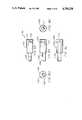
- FIGS. 2a-2care enlarged views of a portion of the pump assembly, including a wheel mounted for rotation within a circular cutout area of the housing, showing the wheel at several positions during the pumping cycle;
- FIG. 3is an enlarged view of the wheel in the centered position for insertion or removal of the tubing
- FIG. 4is a detailed view of one tooth on the pump ring
- FIG. 5is a detailed view of a tooth on the pump ring in the vicinity of the juncture of the first and second cutout regions;
- FIG. 6is a top view of the housing and pump assembly shown in FIG. 1;
- FIG. 7is a side view, partly in section, taken along line 7--7 of FIG. 6;
- FIG. 8a-8eare views of the secondary drive shaft of the pump assembly.
- FIG. 9is an elevation view of the air-in-line, or bubble sensor assembly
- FIG. 10is a top view of the pressure sensor assembly cassette
- FIGS. 11a and 11bare sectional views of the pressure sensor assembly, including the pressure sensor cassette and the transducer and Hall effect circuitry mounted in the housing, FIG. 11a illustrating the preferred arrangement for sensing an increase in fluid pressure and FIG. 11b illustrating the preferred arrangement for sensing a decrease in fluid pressure;
- FIG. 12is a bottom view of the pressure sensor cassette of FIG. 10, with the diaphragms removed;
- FIG. 13is an elevation view in section taken along line 13--13 of FIG. 12;
- FIG. 14is a sectional view of the dual cassette diaphragms for the pressure sensor cassette
- FIG. 15is a top view of the diaphragms of FIG. 14;
- FIG. 16is a sectional view of the diaphragm cover bracket for the pressure sensor cassette
- FIG. 17is a plan view of the pressure sensor cassette and flow control cassette joined together to form a cartridge insert for the housing;
- FIG. 18is a side view, partly in section, of the flow control cassette; .
- FIG. 19is an elevation view of the thumbwheel component of the flow control cassette.
- FIG. 20is an exploded view of a membrane switch used in the preferred embodiment of the invention.
- FIG. 21is a substitute view of the door actuating a membrane switch.
- FIG. 1shows a medical infusion pump apparatus 10 and an associated administration set 12 through which fluids are infused into the patient including whole bood and packed RBC's.
- the pump apparatusincludes a housing 14, a door 16 hinged at 18, and a lever 20.
- the face 22 of the housingincludes two cutout areas.
- the first cutout area 24has a substantially circular profile 26 and the second cutout area 28 has a generally rectangular profile located adjacent to the first cutout area.
- the first cutout area 24has a pump assembly 30 mounted therein and the second cutout area has sensor and control devices mounted therein.
- the door 16preferably includes a catch area 32 for engagement with the latch 34.
- the lever 20 at the lower end of the housingis mounted for pivotal motion in a direction opposite that of the door 16 and draws the latch and door down tight to the housing 14.
- a cartridge assembly including the administration set 12is placed within the pump apparatus 10.
- the administration setincludes a pump tubing segment 36 which is connected to the upper portion of the cassette 38.
- Inlet or supply tubing 42a and delivery tubing 42bare connected to cassette 40.
- cassette 38 and 40are interengaged to form a unitary cartridge and the cartridge with the tubing 36, 42a, 42b connected thereto is inserted as an assembly into the pumping apparatus 10.
- the first cutout portion 24 of the housingincludes a plurality of spaced apart teeth 44 projecting inwardly toward a circular wheel 46.
- the pump tubing segment 36is interposed between the wheel and the teeth.
- the teethmay be formed in the wall of the housing defining the first cutout area, or they may be provided on a separate ring.
- the pump ringwill refer to that circular portion 26 of the housing wall defining the teeth.
- FIGS. 2a-cshow the wheel in three orientations during a full pumping cycle.
- FIG. 2aillustrates the wheel position as a quantity of fluid is pumped out of the tubing segment 36 at 52
- FIG. 2bshows the wheel "trapping" a quantity of blood that has just entered the tubing at 54 in preparation for a peristaltic type transfer along the tubing
- FIG. 2cthe wheel is shown at an intermediate position between those illustrated in FIGS. 2b and 2a.
- the pump assembly of the present inventiondiffers from that of conventional peristaltic pumps in that the wall of the tubing segment 36 is not completely compressed together except at small areas such as at 56 near the teeth 44. Backflow of blood is prevented by appropriately choosing the spacing and size of the teeth, as well as the relationship of diameters and eccentricity of rotation between the wheel and the pump ring.
- the tubeis under sufficient compressive deformation to be substantially closed at the lines of contact between the tubing and the two teeth, i.e. at the crowns of the teeth.
- the tubing 36is closed at 56 and 56'.
- the wheelis closing the tubing against the two teeth on either side of it.
- the tubingis always closed against one or two teeth as it goes through the pumping cycle.
- the tubing between the teethis never closed, nor do the walls of the tube between the teeth ever touch.
- the tubemay not be closed at two teeth in the throat area 58 where the tubing segment 36 enters and leaves the first cutout area 24.
- the pump tubing segment 36substantially completely circumscribes the wheel 46, but the invention could be implemented in less preferred embodiments so long as at least about half of the wheel circumference is bordered by tubing.
- FIG. 3shows the wheel 46 in a centered position relative to the pump ring 26. In this second position, fluid cannot be pumped, but the tubing 36 may be inserted or removed from the space 60 between the ring and the wheel.
- Each of the wheel positions illustrated in FIGS. 2a-2cis a first position in that at least a portion of the wheel is in compressive engagement with the tubing, whereas in the wheel second position illustrated in FIG. 3, none of the tubing is compressively engaged by the wheel.
- the speed of rotation of the wheelcan be controlled to provide a more rapid rotation of the wheel during the portion of the pumping cycle where the extremity of the wheel passes between the positions shown in FIGS. 2a and 2b.
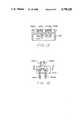
- FIGS. 4 and 5illustrate, in enlarged detail, the preferred shapes of the teeth 44 on the ring.
- ten teethare provided in total, eight of a first type 44a and two of the second type 44b. All the teeth preferably have an apex 64 of about 0.025 inch, and a radius of curvature 66 at the apex of about 0.005 inch.
- the second type of teeth 44bare provided at the throat where the first cutout area joins the second cutout area.
- the radius of curvature 68 of the concave portion of these teethis about 0.032 inch.
- FIG. 6is a top view of the pumping apparatus 10 of FIG. 1 (rotated 90 degrees), and FIG. 7 shows in section the drive shaft assembly for rotating the wheel.
- the pump drive stepper motor 72has a pinion gear extension 74 which is coupled to a gear 76 providing a 5:1 reduction ratio.
- the gear 76is attached to a primary drive shaft 78 which rides in a bearing 80 which is pressed into a bore 82 in the pump housing 14.
- the secondary drive shaft 84is inserted within a bore 86 in the primary drive shaft 78 and held in place by a set screw 88.
- a retaining ring 90is placed in a groove 92 which holds the primary shaft in the bearing.
- the pump wheel 46rides on the secondary drive shaft 84 and is held in place by a knob 96.
- the secondary shaftis spring-loaded 98 in the outward direction relative to the primary drive shaft 78.
- a groove 100 on the body portion 102 of the secondary drive shaft 84cooperates with the set screw 88 in the primary shaft 78 to permit the secondary shaft to be selectively rotated 180 degrees by the knob 96, relative to the primary drive shaft.
- Thismoves the pump wheel 46 relative to the ring 26 in the pump housing 14 from the first position engaging the tubing, to the second position as shown in FIG. 3 for inserting and removing the tubing.
- a bearing 104is inserted into a counter bore in the wheel, and mounted on the extension 106 of the secondary drive shaft.
- the extension axisis, however, offset relative to the axis of the body 102.
- the pumping actionis developed by the wheel pinching off the pump tubing against the teeth on the pump housing and then the offset rotation of the wheel causes this pinching off point to move along the tubing, forcing fluid to be moved, or pumped.
- the knob 96is attached to the end 108 of the secondary drive shaft and, although its primary purpose is to facilitate insertion and removal of the tubing in the pump assembly, the knob can also be used during a standby mode to allow the nurse the check the patency of the intravenous site by rotating the knob in the reverse direction, causing fluid to be moved backwards in the administration set.
- the groove 100preferably spans one-half the circumference of the body portion 102, and includes a rearwardly extending J-type opening 110 at both extremities of the groove.
- the bore 112is adapted to receive spring 98.
- the spring biascauses the set screw to engage one of the openings 110, whereas pushing the knob 96 inward and rotating it causes the set screw to ride the groove 100 until it reaches the other opening 110.
- the pump according to the present inventionminimizes cell damage during the pumping action, and is relatively insensitive to small physical variations in the pump tubing segment such as shore hardness, tubing symmetry, and variations in the relationship of the inner and outer diameters.
- the pump tubing segment 36is made of silicon whereas the tubing 42 is made of PVC. Also, by repeatedly closing off the tubing only in the area close to the teeth of the pump, the problem of spalling has been greatly reduced.
- the air sensor deviceis mounted in the second cutout area 28 of the housing.
- the air sensor assemblyincludes a base portion 122 preferably constituting a portion of the pump housing 14, and a pair of sensor blocks 124 mounted in the base having inner walls 126 defining a trough 128 for supporting a portion of tubing 42' on two side surfaces.
- the tubingwould be a portion of the administration set delivery tubing 42b, but this is not necessary.
- the side walls of the blocksare preferably flat and define a generally V-shaped trough therebetween forming an angle preferably about 30 degrees for cradling the tube.
- Piezoelectric elements 130are located within the sensor blocks 124 such that the transducers are in the flat inner walls and positioned to emit and receive sound waves perpendicularly through the side surfaces of the tube segment 42'.
- the accuracy and repeatability of measurementsrely on a repeatable orientation of the tube relative to the transducers.
- the tube side wallsare urged into a flat, intimate conforming relationship with the block inner walls, by the application of a slight compressive load on the upper surface of the tubing segment.
- at least one half the tubing circumferenceis in contact with the block walls.
- the upper portion of the tubing segmentis compressed by a flat anvil 132 carried by the door 16 such that when the door is closed, a slight compressive stress is applied to the tubing so that it will conform to the shape of the trough.
- the presence or absence of fluidis detected by the magnitude of sound transmission through the tubing with lower transmission rates indicating the presence of air in the tubing.
- the transducer per seis conventional, typically utilizing an ultrasonic frequency of about 1.2 MHZ.
- the present inventionsignificantly increases repeatability of signal from administration set to administration set. Unlike conventional air sensors, which squeeze the tubing between flat upright blocks which create a "dog bone” shape in the tubing, the present invention consistently produces flat, even surfaces at the innerface between the transducer and the tubing.
- the electronics 134 associated with the air sensorare carried behind the housing face, in a printed circuit board 136.
- Other variables relating to the infusion of fluid into the patientare also monitored and displayed to the operator through the sensor assemblies to be described below which are also connected to the electrical components and circuit board shown in FIG. 7.
- the pressure sensor assembly 140is preferably in the form of a cassette 38 as shown in FIGS. 1 and 10.
- the cassette 38includes a body portion 142 adapted to mate with a portion of the recessed profile of the second cutout area 28, and fluid path connecting structure 144, 146 for connecting to the pump tubing segment 36 and either the other administration set tubing 42 or another cassette 40 that provides additional features.
- the pressure sensor cassette 38includes two diaphragms 148, 150, shown in phantom, one for sensing the negative pressure in the inlet direction 152 and the other for sensing the pressure in the outlet direction 154.
- FIGS. 11a and bare views taken along line 11--11 in FIG. 1 in a direction perpendicular to the plane of the drawing, and illustrate the basic features of the inventive pressure sensor assembly 140.
- FIGS. 10-16illustrate the details of the preferred embodiment of this feature of the invention.
- the fluid line 144a connected to the pump and the outlet line 146ahave interposed therebetween a fluid chamber 156.
- the chamberis defined in part by a first diaphragm 150 having a flexure response compatible with the range of pressures to be measured in the chamber.
- the first, or cassette diaphragm 150is arranged to face a transducer assembly 158 preferably mounted in the housing. Thus, the cassette diaphragms are normally not visible to the operator.
- Each diaphragm 150has associated with it a transducer assembly 158, as shown in FIGS. 11a and 11b.
- Transducer assembly 158ais associated with the output flow through tubing 144a, 146a and the transducer assembly 158b is associated with the input flow through tubing 144b, 146b.
- the transducer assembliesinclude a Hall effect integrated circuit 160 spaced from the cassette diaphragm 150, a magnet 162 adjacent the integrated circuit, and rigid connecting means 164 between the magnet and the cassette diaphragm for producing a displacement of the magnet commensurate with the displacement of the diaphragm, thereby generating a signal in the Hall effect circuit indicative of the fluid pressure in the fluid chamber.
- an outer bushing 166is connected between the printed circuit board 136 and the face of the pump housing (see FIG. 7).
- a second, or sensor diaphragm 168is in mating relationship with the cassette diaphragm 150.
- the connecting means 164is preferably in the form of a thin brass translator pin adapted at one end to engage or hold the magnet 162 and at the other end to contact or engage the sensor diaphragm 168 for linear movement therewith.
- a second metal bushing 170is provided within the first bushing for aligning the nose 172 of the pin against the sensor diaphragm.
- the input and output sensor diaphragmhave different shapes.
- the output side diaphragm in FIG. 11ais normally contoured outwardly toward the cassette diaphragm and the input side diaphragm is contoured inwardly away from the cassette diaphragm.
- the purpose of these differences in contouris to eliminate stretching of the rubber diaphragms during a full range of sensing movement.
- the sensor diaphragmsdeform toward a substantially vertical or flat profile as the movement in the sensing direction increases, thus having sufficient material to allow a range of travel of approximately 0.050 inches without stretching the rubber.
- the dual diaphragm 174 shown in FIGS. 14 and 15is a molded silicon rubber part and incorporates O-rings 176 to seal the fluid path.
- a locking bracket 178, shown in FIG. 16,is preferably ultrasonic welded to the cassette body to hold the dual diaphragm in place.
- FIG. 14shows the differences in shape of the output and input side diaphragms 168a, 168b, respectively.
- the output side diaphragm wallis about twice as thick as the input side wall, with both diaphragms having approximately the same radius of curvature.
- the pressure sensor assembly 140 of the present inventioncan resolve pressures to 0.05 psi, due in large part to the transducer arrangement that permits the use of a Hall effect integrated circuit.
- a satisfactory Hall effect circuitis available from the Microswitch Division of the Honeywell Company.
- FIGS. 17-19illustrate the preferred embodiment of the flow control assembly 180 of the present invention, which is in the form of a second cassette 40 adapted for modular engagement with the pressure sensor cassette 38 shown in FIG. 10.
- the flow control assemblyhas a body portion 182 having a pair of upper nozzle receptors 184a, 184b sized for interengagement with the lower nozzles 146a, 146b of the first cassette, and lower inlet 186 and outlet means 188 for fluidly connecting the ends of the administration set 42 to the flow control cassette.
- the flow control functionis accomplished as shown in FIG.
- a flow chamber 190is formed within the body part and a silicon valve 192 is located within the flow chamber in a position to control the flow orifice at valve seat 194 from a fully opened to a fully closed condition.
- the valve 192is coupled to a thumb wheel 196 so that rotation of the thumb wheel causes the valve to open or close the orifice.
- FIG. 19is a plan view of the thumb wheel 196, showing the face containing a cam groove 197 which engages the stem 199 on the valve 192.
- the cam grooveis sloped so that as the thumb wheel is rotated about its axis, the valve stem is pushed toward or away from the valve seat 194.
- the thumb wheel shaft 201is mounted within a bore 203 in the body of the cassette, offset from the inlet flow path 205.
- a button 204is slideably mounted within the bore and projects outwardly from the body of the cassette 40.
- a coil spring 206is disposed in the bore between the button and a stop surface 208 in the cassette body. The spring biases the thumb wheel 196 towards the cassette body such that the valve 192 is normally in the closed position. Rotation of the thumb wheel permits a controlled flow rate through passage 190.
- the button 204may be pushed at any time for instant full flow, and this feature is used primarily for purging the air from the set.
- a hole 209 in the surface of the thumb wheel facing the cutout portion of the pump apparatusis located so that it will mate with a boss 210 projecting from the cutout portion of the pump apparatus. This mating occurs only in the off position of the valve 192.
- the pump door 16cannot be closed when the cassette valve 192 is in the on position, because the boss 210 will not engage the hole 208.
- FIG. 1also shows two membrane switches 212, 214.
- the first switch 212signals the electronics that the door 16 is in the closed position and that the pump 30 and cartridge 202 are ready and in proper position.
- the other switch 214senses a small appendage (not shown) on the pediatrics cassette 38. Actuation of second switch 214 sends a signal to the controller whereby the normal infusion rates and volumes are scaled down to levels appropriate for children. Thus, the operator is not called upon to alter settings in the unit for the pediatrics mode, but merely selects the proper infusion set and installs it.
- FIG. 20illustrates a preferred form of each membrane switch in which four components are stacked together.
- An adhesive wafer 216 with a paper backingis joined to a mylar base member 218 which carries a switch circuit 220 on its underside.
- a mylar base member 222 having a switch circuit 224 on its upper surfaceis located below the first mylar member 218.
- a mylar spacerinterposed therebetween.
- FIG. 21when the door 16 contacts a silicon rubber disk 228 mounted in the housing 14, the disk 228 is depressed, making contact with the membrane switch 212 and causing the opposed circuit portions 220, 224 to make contact and thereby generate a control signal through wires 230.
- the second cassette 40mates with the profile of the lower portion of the second cutout area 28 of the housing.
- the second cassette 40preferably includes a hole 200 located to permit the sensor blocks 124 shown in FIG. 9 to project upwardly therethrough, whereby the administration set tubing 42 connected to the nozzle receptor 184a or outlet 188 lies in the trough of the air sensor assembly.
- the pump assemblycan be used alone or with other sensor devices.
- the pump assembly 30is used with the air-in-line sensor assembly 120 and the pressure assembly 140 of the present invention.
- the flow control cassette 40is connected to the pressure sensor cassette 38, as shown in FIG. 18 and the resulting cartridge 202 is located within the profile of the second cutout area of the housing.
- the cartridge 202 having both the pressure sensing cassette and the flow control cassettemay be used as a standard gravity set assembly without actuation of the pump, if desired.
- the door 16is opened by rotating the latch 32 away from the pump housing 14 and swinging the door outward.
- the pump knob 96is grasped and pushed in as far as it will go, then rotated to the left. This centers the pump wheel 46 within the ring 26, away from the pump teeth 44, to provide clearance for the installation of the silicon pump tubing segment 36.
- the upper inlet and upper outlet nozzles 144a, 144b of the first cassette 38are connected to the ends of the pump tubing segment 36.
- the second cassette 40is then connected to the first cassette 38.
- the tubing 42a and 42bis connected to the second cassette 40.
- the complete cartridge unitis then placed in the first and second cutout areas of the pump housing.
- the knob 96When the pump tubing is properly aligned between the wheel 46 and the pump ring 26, the knob 96 is pushed in as far as it will go and rotated to the right to urge the wheel into compressive engagement with the tubing.
- the door 16is closed over the cutout areas and the lever 20 rotated to the right.
- the doorhas another circular hole 204 sized and located such that the door will not close unless the knob 96 is in the first position for pumping fluid.
Landscapes
- Health & Medical Sciences (AREA)
- Vascular Medicine (AREA)
- Engineering & Computer Science (AREA)
- Anesthesiology (AREA)
- Biomedical Technology (AREA)
- Heart & Thoracic Surgery (AREA)
- Hematology (AREA)
- Life Sciences & Earth Sciences (AREA)
- Animal Behavior & Ethology (AREA)
- General Health & Medical Sciences (AREA)
- Public Health (AREA)
- Veterinary Medicine (AREA)
- Emergency Medicine (AREA)
- Infusion, Injection, And Reservoir Apparatuses (AREA)
Abstract
Description
Claims (12)
Priority Applications (2)
| Application Number | Priority Date | Filing Date | Title |
|---|---|---|---|
| US06/931,506US4758228A (en) | 1986-11-17 | 1986-11-17 | Medical infusion pump with sensors |
| US07/178,277US4856339A (en) | 1986-11-17 | 1988-04-06 | Medical infusion pump with sensors |
Applications Claiming Priority (1)
| Application Number | Priority Date | Filing Date | Title |
|---|---|---|---|
| US06/931,506US4758228A (en) | 1986-11-17 | 1986-11-17 | Medical infusion pump with sensors |
Related Child Applications (1)
| Application Number | Title | Priority Date | Filing Date |
|---|---|---|---|
| US07/178,277DivisionUS4856339A (en) | 1986-11-17 | 1988-04-06 | Medical infusion pump with sensors |
Publications (1)
| Publication Number | Publication Date |
|---|---|
| US4758228Atrue US4758228A (en) | 1988-07-19 |
Family
ID=25460887
Family Applications (1)
| Application Number | Title | Priority Date | Filing Date |
|---|---|---|---|
| US06/931,506Expired - Fee RelatedUS4758228A (en) | 1986-11-17 | 1986-11-17 | Medical infusion pump with sensors |
Country Status (1)
| Country | Link |
|---|---|
| US (1) | US4758228A (en) |
Cited By (113)
| Publication number | Priority date | Publication date | Assignee | Title |
|---|---|---|---|---|
| US4821558A (en)* | 1987-05-01 | 1989-04-18 | Abbott Laboratories | Ultrasonic detector |
| US4856339A (en)* | 1986-11-17 | 1989-08-15 | Centaur Sciences, Inc. | Medical infusion pump with sensors |
| EP0355021A3 (en)* | 1988-08-16 | 1990-08-22 | Fresenius Ag | Pressure infusion device |
| US4966528A (en)* | 1988-02-10 | 1990-10-30 | Abel Pumpen Gmbh & Co. Kg | Apparatus for controlling the hydraulic circuit of a piston diaphragm pump |
| US5000664A (en)* | 1989-06-07 | 1991-03-19 | Abbott Laboratories | Apparatus and method to test for valve leakage in a pump assembly |
| US5000663A (en)* | 1989-09-05 | 1991-03-19 | Pacesetter Infusion, Ltd. | Automatic tubing lock for ultrasonic sensor interface |
| EP0411543A3 (en)* | 1989-07-31 | 1991-09-11 | Terumo Kabushiki Kaisha | Peristaltic pump |
| EP0447985A1 (en)* | 1990-03-15 | 1991-09-25 | Abbott Laboratories | Positive displacement pump |
| US5053747A (en)* | 1989-09-05 | 1991-10-01 | Pacesetter Infusion, Inc. | Ultrasonic air-in-line detector self-test technique |
| US5057081A (en)* | 1990-06-15 | 1991-10-15 | Sherwood Medical Company | Peristaltic infusion device |
| US5064412A (en)* | 1989-09-05 | 1991-11-12 | Pacesetter Infusion, Ltd. | Ultrasonic air-in-line detector for a medication infusion system |
| EP0396003A3 (en)* | 1989-04-28 | 1991-11-27 | Sharp Kabushiki Kaisha | Air detector for use in infusion pump |
| US5094820A (en)* | 1990-04-26 | 1992-03-10 | Minnesota Mining And Manufacturing Company | Pump and calibration system |
| US5103211A (en)* | 1989-11-02 | 1992-04-07 | Ivac Corporation | Apparatus for detecting fluid line occlusion |
| US5120096A (en)* | 1990-08-23 | 1992-06-09 | Baxter International Inc. | Misloaded IV tube detector for an IV pump |
| US5126616A (en)* | 1989-09-05 | 1992-06-30 | Pacesetter Infusion, Ltd. | Ultrasonic transducer electrical interface assembly |
| US5127908A (en)* | 1990-06-15 | 1992-07-07 | Sherwood Medical Company | Peristaltic infusion device |
| US5133650A (en)* | 1990-06-15 | 1992-07-28 | Sherwood Medical Company | Infusion device rotor shield |
| US5147312A (en)* | 1990-06-15 | 1992-09-15 | Sherwood Medical Company | Peristaltic infusion device drip chamber yoke |
| US5154700A (en)* | 1990-08-13 | 1992-10-13 | Danby Medical Limited | Arrangement for monitoring fluid flow during intravenous supply to a patient |
| US5158528A (en)* | 1990-06-15 | 1992-10-27 | Sherwood Medical Company | Peristaltic infusion device and charger unit |
| US5171029A (en)* | 1990-04-26 | 1992-12-15 | Minnesota Mining And Manufacturing Company | Seal construction for pump apparatus |
| US5176631A (en)* | 1989-09-05 | 1993-01-05 | Pacesetter Infusion, Ltd. | Ultrasonic air-in-line detector for detecting entrained air in a medication infusion system |
| US5181842A (en)* | 1990-06-15 | 1993-01-26 | Sherwood Medical Company | Peristaltic infusion device |
| US5190522A (en)* | 1989-01-20 | 1993-03-02 | Institute Of Biocybernetics And Biomedical Engineering P.A.S. | Device for monitoring the operation of a delivery system and the method of use thereof |
| US5201711A (en)* | 1987-09-30 | 1993-04-13 | Sherwood Medical Company | Safety interlock system for medical fluid pumps |
| US5205819A (en)* | 1989-05-11 | 1993-04-27 | Bespak Plc | Pump apparatus for biomedical use |
| US5211626A (en)* | 1987-05-01 | 1993-05-18 | Product Innovation Holdings Ltd. | Medical infusion apparatus |
| US5250027A (en)* | 1991-10-08 | 1993-10-05 | Sherwood Medical Company | Peristaltic infusion device with backpack sensor |
| USD342231S (en) | 1991-04-19 | 1993-12-14 | Sherwood Medical Company | Charger unit for a peristaltic infusion pump |
| US5278072A (en)* | 1990-04-26 | 1994-01-11 | Minnesota Mining And Manufacturing Company | Calibration system and housing |
| USD347472S (en) | 1991-09-23 | 1994-05-31 | Sherwood Medical Company | Combined peristaltic infusion pump and charger unit |
| USD348730S (en) | 1991-04-11 | 1994-07-12 | Sherwood Medical Company | Peristaltic infusion pump |
| US5340290A (en)* | 1992-12-21 | 1994-08-23 | Scilog, Inc. | Double feed peristaltic pump |
| US5348706A (en)* | 1990-04-26 | 1994-09-20 | Minnesota Mining And Manufacturing Company | Calibration system and method for making |
| EP0624382A1 (en)* | 1993-05-13 | 1994-11-17 | Association Pour L'essor De La Transfusion Sanguine Dans La Region Du Nord | Peristaltic security clamp |
| US5395320A (en)* | 1992-06-09 | 1995-03-07 | Sabratek Corporation | Programmable infusion pump with interchangeable tubing |
| US5399171A (en)* | 1991-06-10 | 1995-03-21 | Baxter International Inc. | Intravenous metering monitoring device |
| US5583280A (en)* | 1995-01-26 | 1996-12-10 | Abbott Laboratories | Air bubble sensor with simplified mounting of piezo elements |
| US5609575A (en)* | 1994-04-11 | 1997-03-11 | Graseby Medical Limited | Infusion pump and method with dose-rate calculation |
| US5620312A (en)* | 1995-03-06 | 1997-04-15 | Sabratek Corporation | Infusion pump with dual-latching mechanism |
| US5628619A (en)* | 1995-03-06 | 1997-05-13 | Sabratek Corporation | Infusion pump having power-saving modes |
| US5634907A (en)* | 1994-12-22 | 1997-06-03 | Sandoz Nutrition Ltd. | System for detection of fluid infusion |
| US5637093A (en)* | 1995-03-06 | 1997-06-10 | Sabratek Corporation | Infusion pump with selective backlight |
| WO1997037703A1 (en)* | 1996-04-10 | 1997-10-16 | Baxter International Inc. | Volumetric infusion pump |
| US5693008A (en)* | 1995-06-07 | 1997-12-02 | Cobe Laboratories, Inc. | Dialysis blood tubing set |
| US5795327A (en)* | 1995-03-06 | 1998-08-18 | Sabratek Corporation | Infusion pump with historical data recording |
| WO1998036254A1 (en)* | 1997-02-12 | 1998-08-20 | Medtronic, Inc. | Method and apparatus for sensing fluid pressure |
| US5904668A (en)* | 1995-03-06 | 1999-05-18 | Sabratek Corporation | Cassette for an infusion pump |
| AU721076B2 (en)* | 1996-04-10 | 2000-06-22 | Baxter International Inc. | A housing for an infusion pump |
| US6106498A (en)* | 1995-07-06 | 2000-08-22 | Disetronic Licensing Ag | Disposable cassette for connection to a liquid drug infusion pump |
| US6264634B1 (en)* | 1997-07-25 | 2001-07-24 | Seiko Instruments Inc. | Implant type chemical supply device |
| US6280406B1 (en) | 1997-09-12 | 2001-08-28 | Gambro, Inc | Extracorporeal blood processing system |
| US6468242B1 (en) | 1998-03-06 | 2002-10-22 | Baxter International Inc. | Medical apparatus with patient data recording |
| US20050267401A1 (en)* | 2004-05-25 | 2005-12-01 | Sherwood Services, Ag. | Safety interlock system for an enteral feeding pump |
| US20060004327A1 (en)* | 2002-09-26 | 2006-01-05 | Sherwood Services Ag | Safety interlock system for an enteral feeding pump |
| US20060195045A1 (en)* | 2005-02-14 | 2006-08-31 | Gable Jennifer H | Fluid handling cassette having a fluid transport network |
| US20060216209A1 (en)* | 2005-02-14 | 2006-09-28 | Braig James R | Analyte detection system with distributed sensing |
| US20070191990A1 (en)* | 2005-08-12 | 2007-08-16 | Hao Duan | Flow measurement and control with bubble detection |
| US20070240447A1 (en)* | 1998-04-21 | 2007-10-18 | Wayne Noda | Heating/Cooling System for Indwelling Heat Exchange Catheter |
| WO2006076339A3 (en)* | 2005-01-14 | 2007-10-25 | David T Bach | Drive technology for peristaltic and rotary pumps |
| US20080058711A1 (en)* | 2003-07-31 | 2008-03-06 | Frederic Neftel | System For Performing Peritoneal Dialysis |
| US20080294097A1 (en)* | 2004-09-03 | 2008-11-27 | Ribotkisul Co., Ltd. | Portable Infusion Set |
| US20090157040A1 (en)* | 2007-12-17 | 2009-06-18 | Hospira, Inc. | Differential pressure based flow sensor assembly for medication delivery monitoring and method of using the same |
| US20090288497A1 (en)* | 2008-05-23 | 2009-11-26 | Hospira, Inc. | Cassette for differential pressure based medication delivery flow sensor assembly for medication delivery monitoring and method of making the same |
| US20100057058A1 (en)* | 2008-09-02 | 2010-03-04 | Hospira, Inc. | Cassette for use in a medication delivery flow sensor assembly and method of making the same |
| US20100114027A1 (en)* | 2008-11-05 | 2010-05-06 | Hospira, Inc. | Fluid medication delivery systems for delivery monitoring of secondary medications |
| US20100198155A1 (en)* | 2009-01-30 | 2010-08-05 | Hospira, Inc. | Cassette for differential pressure based medication delivery flow sensor assembly for medication delivery monitoring and method of making the same |
| US20100240964A1 (en)* | 2005-02-14 | 2010-09-23 | Sterling Bernhard B | System and method for determining a treatment dose for a patient |
| US20100280486A1 (en)* | 2009-04-29 | 2010-11-04 | Hospira, Inc. | System and method for delivering and monitoring medication |
| US8105269B2 (en) | 2008-10-24 | 2012-01-31 | Baxter International Inc. | In situ tubing measurements for infusion pumps |
| US8137083B2 (en) | 2009-03-11 | 2012-03-20 | Baxter International Inc. | Infusion pump actuators, system and method for controlling medical fluid flowrate |
| US8382447B2 (en) | 2009-12-31 | 2013-02-26 | Baxter International, Inc. | Shuttle pump with controlled geometry |
| EP2550518A4 (en)* | 2010-03-24 | 2013-09-04 | Carefusion 303 Inc | SYSTEM AND METHOD FOR PRESSURE DETECTION |
| US8567235B2 (en) | 2010-06-29 | 2013-10-29 | Baxter International Inc. | Tube measurement technique using linear actuator and pressure sensor |
| US8786838B2 (en) | 2001-11-08 | 2014-07-22 | Optiscan Biomedical Corporation | Analyte monitoring systems and methods |
| US8928877B2 (en) | 2011-07-06 | 2015-01-06 | Optiscan Biomedical Corporation | Sample cell for fluid analysis system |
| US8936755B2 (en) | 2005-03-02 | 2015-01-20 | Optiscan Biomedical Corporation | Bodily fluid composition analyzer with disposable cassette |
| US20160213843A1 (en)* | 2015-01-26 | 2016-07-28 | Becton, Dickinson And Company | Smart portable infusion pump |
| US9523359B1 (en)* | 2013-02-04 | 2016-12-20 | Robert C. Geschwender | Linear peristaltic pump having opposing staggered curved surfaces |
| US9554742B2 (en) | 2009-07-20 | 2017-01-31 | Optiscan Biomedical Corporation | Fluid analysis system |
| WO2017018974A1 (en) | 2015-07-24 | 2017-02-02 | Zevex, Inc. | Magnetic pressure sensing system for an infusion pump |
| US9561001B2 (en) | 2005-10-06 | 2017-02-07 | Optiscan Biomedical Corporation | Fluid handling cassette system for body fluid analyzer |
| US9863837B2 (en) | 2013-12-18 | 2018-01-09 | OptiScan Biomedical Coporation | Systems and methods for detecting leaks |
| US10022498B2 (en) | 2011-12-16 | 2018-07-17 | Icu Medical, Inc. | System for monitoring and delivering medication to a patient and method of using the same to minimize the risks associated with automated therapy |
| US10143795B2 (en) | 2014-08-18 | 2018-12-04 | Icu Medical, Inc. | Intravenous pole integrated power, control, and communication system and method for an infusion pump |
| US10166328B2 (en) | 2013-05-29 | 2019-01-01 | Icu Medical, Inc. | Infusion system which utilizes one or more sensors and additional information to make an air determination regarding the infusion system |
| US10201303B2 (en) | 2009-07-20 | 2019-02-12 | Optiscan Biomedical Corporation | Fluid analysis system |
| US10342917B2 (en) | 2014-02-28 | 2019-07-09 | Icu Medical, Inc. | Infusion system and method which utilizes dual wavelength optical air-in-line detection |
| US10430761B2 (en) | 2011-08-19 | 2019-10-01 | Icu Medical, Inc. | Systems and methods for a graphical interface including a graphical representation of medical data |
| US10463788B2 (en) | 2012-07-31 | 2019-11-05 | Icu Medical, Inc. | Patient care system for critical medications |
| US10578474B2 (en) | 2012-03-30 | 2020-03-03 | Icu Medical, Inc. | Air detection system and method for detecting air in a pump of an infusion system |
| US10596316B2 (en) | 2013-05-29 | 2020-03-24 | Icu Medical, Inc. | Infusion system and method of use which prevents over-saturation of an analog-to-digital converter |
| US10635784B2 (en) | 2007-12-18 | 2020-04-28 | Icu Medical, Inc. | User interface improvements for medical devices |
| US10656894B2 (en) | 2017-12-27 | 2020-05-19 | Icu Medical, Inc. | Synchronized display of screen content on networked devices |
| US10850024B2 (en) | 2015-03-02 | 2020-12-01 | Icu Medical, Inc. | Infusion system, device, and method having advanced infusion features |
| US10874793B2 (en) | 2013-05-24 | 2020-12-29 | Icu Medical, Inc. | Multi-sensor infusion system for detecting air or an occlusion in the infusion system |
| US10918787B2 (en) | 2015-05-26 | 2021-02-16 | Icu Medical, Inc. | Disposable infusion fluid delivery device for programmable large volume drug delivery |
| CN112689521A (en)* | 2018-09-11 | 2021-04-20 | 大研医器株式会社 | Connecting member, pump housing and injection device provided with same, and liquid confirmation method using same |
| WO2021081283A1 (en)* | 2019-10-24 | 2021-04-29 | Amgen Inc. | Drug delivery device |
| US11135360B1 (en) | 2020-12-07 | 2021-10-05 | Icu Medical, Inc. | Concurrent infusion with common line auto flush |
| USD939079S1 (en) | 2019-08-22 | 2021-12-21 | Icu Medical, Inc. | Infusion pump |
| US11213619B2 (en) | 2013-11-11 | 2022-01-04 | Icu Medical, Inc. | Thermal management system and method for medical devices |
| US11246985B2 (en) | 2016-05-13 | 2022-02-15 | Icu Medical, Inc. | Infusion pump system and method with common line auto flush |
| US11278671B2 (en) | 2019-12-04 | 2022-03-22 | Icu Medical, Inc. | Infusion pump with safety sequence keypad |
| US11324888B2 (en) | 2016-06-10 | 2022-05-10 | Icu Medical, Inc. | Acoustic flow sensor for continuous medication flow measurements and feedback control of infusion |
| US11331037B2 (en)* | 2016-02-19 | 2022-05-17 | Aegea Medical Inc. | Methods and apparatus for determining the integrity of a bodily cavity |
| US11344673B2 (en) | 2014-05-29 | 2022-05-31 | Icu Medical, Inc. | Infusion system and pump with configurable closed loop delivery rate catch-up |
| US11344668B2 (en) | 2014-12-19 | 2022-05-31 | Icu Medical, Inc. | Infusion system with concurrent TPN/insulin infusion |
| US11883361B2 (en) | 2020-07-21 | 2024-01-30 | Icu Medical, Inc. | Fluid transfer devices and methods of use |
| USD1052728S1 (en) | 2021-11-12 | 2024-11-26 | Icu Medical, Inc. | Medical fluid infusion pump |
| US12350233B2 (en) | 2021-12-10 | 2025-07-08 | Icu Medical, Inc. | Medical fluid compounding systems with coordinated flow control |
| USD1091564S1 (en) | 2021-10-13 | 2025-09-02 | Icu Medical, Inc. | Display screen or portion thereof with graphical user interface for a medical device |
Citations (7)
| Publication number | Priority date | Publication date | Assignee | Title |
|---|---|---|---|---|
| US3912168A (en)* | 1975-01-30 | 1975-10-14 | Teledyne Ind Inc Teledyne Aqua | Irrigation lavage |
| US4155362A (en)* | 1976-01-26 | 1979-05-22 | Baxter Travenol Laboratories, Inc. | Method and apparatus for metered infusion of fluids |
| US4187057A (en)* | 1978-01-11 | 1980-02-05 | Stewart-Naumann Laboratories, Inc. | Peristaltic infusion pump and disposable cassette for use therewith |
| US4210138A (en)* | 1977-12-02 | 1980-07-01 | Baxter Travenol Laboratories, Inc. | Metering apparatus for a fluid infusion system with flow control station |
| US4452599A (en)* | 1981-10-26 | 1984-06-05 | The Hospital For Sick Children | Method of delivering medical liquid by peristaltic tube pump |
| US4487601A (en)* | 1983-06-20 | 1984-12-11 | Extracorporeal Medical Specialties, Inc. | Bubble detector circuit with variable reference level |
| US4604090A (en)* | 1983-11-22 | 1986-08-05 | Consolidated Controls Corporation | Compact implantable medication infusion device |
- 1986
- 1986-11-17USUS06/931,506patent/US4758228A/ennot_activeExpired - Fee Related
Patent Citations (7)
| Publication number | Priority date | Publication date | Assignee | Title |
|---|---|---|---|---|
| US3912168A (en)* | 1975-01-30 | 1975-10-14 | Teledyne Ind Inc Teledyne Aqua | Irrigation lavage |
| US4155362A (en)* | 1976-01-26 | 1979-05-22 | Baxter Travenol Laboratories, Inc. | Method and apparatus for metered infusion of fluids |
| US4210138A (en)* | 1977-12-02 | 1980-07-01 | Baxter Travenol Laboratories, Inc. | Metering apparatus for a fluid infusion system with flow control station |
| US4187057A (en)* | 1978-01-11 | 1980-02-05 | Stewart-Naumann Laboratories, Inc. | Peristaltic infusion pump and disposable cassette for use therewith |
| US4452599A (en)* | 1981-10-26 | 1984-06-05 | The Hospital For Sick Children | Method of delivering medical liquid by peristaltic tube pump |
| US4487601A (en)* | 1983-06-20 | 1984-12-11 | Extracorporeal Medical Specialties, Inc. | Bubble detector circuit with variable reference level |
| US4604090A (en)* | 1983-11-22 | 1986-08-05 | Consolidated Controls Corporation | Compact implantable medication infusion device |
Cited By (195)
| Publication number | Priority date | Publication date | Assignee | Title |
|---|---|---|---|---|
| US4856339A (en)* | 1986-11-17 | 1989-08-15 | Centaur Sciences, Inc. | Medical infusion pump with sensors |
| US4944191A (en)* | 1987-05-01 | 1990-07-31 | Abbott Laboratories | Ultrasonic detector |
| US5211626A (en)* | 1987-05-01 | 1993-05-18 | Product Innovation Holdings Ltd. | Medical infusion apparatus |
| US4821558A (en)* | 1987-05-01 | 1989-04-18 | Abbott Laboratories | Ultrasonic detector |
| US6017326A (en)* | 1987-09-30 | 2000-01-25 | Sherwood Services, Ag | Safety interlock system for medical fluid pumps |
| US5201711A (en)* | 1987-09-30 | 1993-04-13 | Sherwood Medical Company | Safety interlock system for medical fluid pumps |
| US4966528A (en)* | 1988-02-10 | 1990-10-30 | Abel Pumpen Gmbh & Co. Kg | Apparatus for controlling the hydraulic circuit of a piston diaphragm pump |
| EP0355021A3 (en)* | 1988-08-16 | 1990-08-22 | Fresenius Ag | Pressure infusion device |
| US5190522A (en)* | 1989-01-20 | 1993-03-02 | Institute Of Biocybernetics And Biomedical Engineering P.A.S. | Device for monitoring the operation of a delivery system and the method of use thereof |
| US5102392A (en)* | 1989-04-28 | 1992-04-07 | Sharp Kabushiki Kaisha | Air detector for use in infusion pump |
| EP0396003A3 (en)* | 1989-04-28 | 1991-11-27 | Sharp Kabushiki Kaisha | Air detector for use in infusion pump |
| US5205819A (en)* | 1989-05-11 | 1993-04-27 | Bespak Plc | Pump apparatus for biomedical use |
| US5000664A (en)* | 1989-06-07 | 1991-03-19 | Abbott Laboratories | Apparatus and method to test for valve leakage in a pump assembly |
| EP0411543A3 (en)* | 1989-07-31 | 1991-09-11 | Terumo Kabushiki Kaisha | Peristaltic pump |
| US5053747A (en)* | 1989-09-05 | 1991-10-01 | Pacesetter Infusion, Inc. | Ultrasonic air-in-line detector self-test technique |
| US5064412A (en)* | 1989-09-05 | 1991-11-12 | Pacesetter Infusion, Ltd. | Ultrasonic air-in-line detector for a medication infusion system |
| US5176631A (en)* | 1989-09-05 | 1993-01-05 | Pacesetter Infusion, Ltd. | Ultrasonic air-in-line detector for detecting entrained air in a medication infusion system |
| US5126616A (en)* | 1989-09-05 | 1992-06-30 | Pacesetter Infusion, Ltd. | Ultrasonic transducer electrical interface assembly |
| US5000663A (en)* | 1989-09-05 | 1991-03-19 | Pacesetter Infusion, Ltd. | Automatic tubing lock for ultrasonic sensor interface |
| US5103211A (en)* | 1989-11-02 | 1992-04-07 | Ivac Corporation | Apparatus for detecting fluid line occlusion |
| EP0447985A1 (en)* | 1990-03-15 | 1991-09-25 | Abbott Laboratories | Positive displacement pump |
| AU641734B2 (en)* | 1990-03-15 | 1993-09-30 | Abbott Laboratories | A sensor for detecting fluid flow from a positive displacement pump |
| US5278072A (en)* | 1990-04-26 | 1994-01-11 | Minnesota Mining And Manufacturing Company | Calibration system and housing |
| US5171029A (en)* | 1990-04-26 | 1992-12-15 | Minnesota Mining And Manufacturing Company | Seal construction for pump apparatus |
| US5094820A (en)* | 1990-04-26 | 1992-03-10 | Minnesota Mining And Manufacturing Company | Pump and calibration system |
| US5420038A (en)* | 1990-04-26 | 1995-05-30 | Minnesota Mining And Manufacturing Company | Calibration system and housing |
| US5348706A (en)* | 1990-04-26 | 1994-09-20 | Minnesota Mining And Manufacturing Company | Calibration system and method for making |
| US5158528A (en)* | 1990-06-15 | 1992-10-27 | Sherwood Medical Company | Peristaltic infusion device and charger unit |
| US5181842A (en)* | 1990-06-15 | 1993-01-26 | Sherwood Medical Company | Peristaltic infusion device |
| US5147312A (en)* | 1990-06-15 | 1992-09-15 | Sherwood Medical Company | Peristaltic infusion device drip chamber yoke |
| US5133650A (en)* | 1990-06-15 | 1992-07-28 | Sherwood Medical Company | Infusion device rotor shield |
| US5127908A (en)* | 1990-06-15 | 1992-07-07 | Sherwood Medical Company | Peristaltic infusion device |
| US5057081A (en)* | 1990-06-15 | 1991-10-15 | Sherwood Medical Company | Peristaltic infusion device |
| US5154700A (en)* | 1990-08-13 | 1992-10-13 | Danby Medical Limited | Arrangement for monitoring fluid flow during intravenous supply to a patient |
| US5120096A (en)* | 1990-08-23 | 1992-06-09 | Baxter International Inc. | Misloaded IV tube detector for an IV pump |
| USD348730S (en) | 1991-04-11 | 1994-07-12 | Sherwood Medical Company | Peristaltic infusion pump |
| USD342231S (en) | 1991-04-19 | 1993-12-14 | Sherwood Medical Company | Charger unit for a peristaltic infusion pump |
| US5399171A (en)* | 1991-06-10 | 1995-03-21 | Baxter International Inc. | Intravenous metering monitoring device |
| USD347472S (en) | 1991-09-23 | 1994-05-31 | Sherwood Medical Company | Combined peristaltic infusion pump and charger unit |
| US5250027A (en)* | 1991-10-08 | 1993-10-05 | Sherwood Medical Company | Peristaltic infusion device with backpack sensor |
| US5395320A (en)* | 1992-06-09 | 1995-03-07 | Sabratek Corporation | Programmable infusion pump with interchangeable tubing |
| US5340290A (en)* | 1992-12-21 | 1994-08-23 | Scilog, Inc. | Double feed peristaltic pump |
| EP0624382A1 (en)* | 1993-05-13 | 1994-11-17 | Association Pour L'essor De La Transfusion Sanguine Dans La Region Du Nord | Peristaltic security clamp |
| FR2705427A1 (en)* | 1993-05-13 | 1994-11-25 | Aetsrn | Peristaltic forceps, especially for automatic blood collection apparatus. |
| US5609575A (en)* | 1994-04-11 | 1997-03-11 | Graseby Medical Limited | Infusion pump and method with dose-rate calculation |
| US5634907A (en)* | 1994-12-22 | 1997-06-03 | Sandoz Nutrition Ltd. | System for detection of fluid infusion |
| US5583280A (en)* | 1995-01-26 | 1996-12-10 | Abbott Laboratories | Air bubble sensor with simplified mounting of piezo elements |
| US5993420A (en)* | 1995-03-06 | 1999-11-30 | Sabratek Corporation | Cassette for an infusion pump |
| US5628619A (en)* | 1995-03-06 | 1997-05-13 | Sabratek Corporation | Infusion pump having power-saving modes |
| US5620312A (en)* | 1995-03-06 | 1997-04-15 | Sabratek Corporation | Infusion pump with dual-latching mechanism |
| US5766155A (en)* | 1995-03-06 | 1998-06-16 | Sabratek Corporation | Infusion pump with selective backlight |
| US5791880A (en)* | 1995-03-06 | 1998-08-11 | Sabratek Corporation | Infusion pump having power-saving modes |
| US5795327A (en)* | 1995-03-06 | 1998-08-18 | Sabratek Corporation | Infusion pump with historical data recording |
| US5637093A (en)* | 1995-03-06 | 1997-06-10 | Sabratek Corporation | Infusion pump with selective backlight |
| US5904668A (en)* | 1995-03-06 | 1999-05-18 | Sabratek Corporation | Cassette for an infusion pump |
| US5693008A (en)* | 1995-06-07 | 1997-12-02 | Cobe Laboratories, Inc. | Dialysis blood tubing set |
| US6106498A (en)* | 1995-07-06 | 2000-08-22 | Disetronic Licensing Ag | Disposable cassette for connection to a liquid drug infusion pump |
| US6129517A (en)* | 1996-04-10 | 2000-10-10 | Baxter International Inc | Volumetric infusion pump |
| WO1997037703A1 (en)* | 1996-04-10 | 1997-10-16 | Baxter International Inc. | Volumetric infusion pump |
| AU721076B2 (en)* | 1996-04-10 | 2000-06-22 | Baxter International Inc. | A housing for an infusion pump |
| EP0893132A3 (en)* | 1996-04-10 | 1999-10-20 | Baxter International Inc. | Volumetric infusion pump |
| US6013057A (en)* | 1996-04-10 | 2000-01-11 | Baxter International Inc. | Volumetric infusion pump |
| WO1998036254A1 (en)* | 1997-02-12 | 1998-08-20 | Medtronic, Inc. | Method and apparatus for sensing fluid pressure |
| US6250164B1 (en) | 1997-02-12 | 2001-06-26 | Medtronic, Inc. | Measurement of fluid pressure within a tube |
| US6264634B1 (en)* | 1997-07-25 | 2001-07-24 | Seiko Instruments Inc. | Implant type chemical supply device |
| US6280406B1 (en) | 1997-09-12 | 2001-08-28 | Gambro, Inc | Extracorporeal blood processing system |
| US6764460B2 (en) | 1997-09-12 | 2004-07-20 | Gambro Inc. | Extracorporeal blood processing system |
| US6468242B1 (en) | 1998-03-06 | 2002-10-22 | Baxter International Inc. | Medical apparatus with patient data recording |
| US8317491B2 (en)* | 1998-04-21 | 2012-11-27 | Zoll Circulation, Inc. | Heating/cooling system for indwelling heat exchange catheter |
| US20070240447A1 (en)* | 1998-04-21 | 2007-10-18 | Wayne Noda | Heating/Cooling System for Indwelling Heat Exchange Catheter |
| US8790304B2 (en) | 2001-09-25 | 2014-07-29 | Zoll Circulation, Inc. | Tubing set to interconnect heating/cooling system and indwelling heat exchange catheter |
| US8690826B2 (en) | 2001-09-25 | 2014-04-08 | Zoll Circulation, Inc. | Heating/ cooling system for indwelling heat exchange catheter |
| US9624926B2 (en) | 2001-09-25 | 2017-04-18 | Zoll Circulation, Inc. | Heating/ cooling system for indwelling heat exchange catheter |
| US9907504B2 (en) | 2001-11-08 | 2018-03-06 | Optiscan Biomedical Corporation | Analyte monitoring systems and methods |
| US8786838B2 (en) | 2001-11-08 | 2014-07-22 | Optiscan Biomedical Corporation | Analyte monitoring systems and methods |
| US9404852B2 (en) | 2001-11-08 | 2016-08-02 | Optiscan Biomedical Corporation | Analyte monitoring systems and methods |
| US20060004327A1 (en)* | 2002-09-26 | 2006-01-05 | Sherwood Services Ag | Safety interlock system for an enteral feeding pump |
| US7537579B2 (en) | 2002-09-26 | 2009-05-26 | Covidien Ag | Safety interlock system for an enteral feeding pump |
| US10172992B2 (en) | 2003-07-31 | 2019-01-08 | Debiotech S.A. | System for performing peritoneal dialysis |
| US20080058711A1 (en)* | 2003-07-31 | 2008-03-06 | Frederic Neftel | System For Performing Peritoneal Dialysis |
| US8585634B2 (en)* | 2003-07-31 | 2013-11-19 | Debiotech S.A. | System for performing peritoneal dialysis |
| US20050267401A1 (en)* | 2004-05-25 | 2005-12-01 | Sherwood Services, Ag. | Safety interlock system for an enteral feeding pump |
| US20080294097A1 (en)* | 2004-09-03 | 2008-11-27 | Ribotkisul Co., Ltd. | Portable Infusion Set |
| WO2006076339A3 (en)* | 2005-01-14 | 2007-10-25 | David T Bach | Drive technology for peristaltic and rotary pumps |
| US10568555B2 (en) | 2005-02-14 | 2020-02-25 | Optiscan Biomedical Corporation | Fluid handling cassette |
| US8197770B2 (en) | 2005-02-14 | 2012-06-12 | Optiscan Biomedical Corporation | Fluid handling cassette having a spectroscopic sample cell |
| US20100240964A1 (en)* | 2005-02-14 | 2010-09-23 | Sterling Bernhard B | System and method for determining a treatment dose for a patient |
| US8992443B2 (en) | 2005-02-14 | 2015-03-31 | Optiscan Biomedical Corporation | Fluid handling cassette |
| US7481787B2 (en) | 2005-02-14 | 2009-01-27 | Optiscan Biomedical Corporation | Fluid handling cassette having a spectroscopic sample cell |
| US20060216209A1 (en)* | 2005-02-14 | 2006-09-28 | Braig James R | Analyte detection system with distributed sensing |
| US20110011167A1 (en)* | 2005-02-14 | 2011-01-20 | Gable Jennifer H | Fluid handling cassette with a fluid control interface and sample separator |
| US7907985B2 (en) | 2005-02-14 | 2011-03-15 | Optiscan Biomedical Corporation | Fluid handling cassette with a fluid control interface and sample separator |
| US20110190606A1 (en)* | 2005-02-14 | 2011-08-04 | Optiscan Biomedical Corporation | Fluid handling cassette |
| US20060195045A1 (en)* | 2005-02-14 | 2006-08-31 | Gable Jennifer H | Fluid handling cassette having a fluid transport network |
| US20060194325A1 (en)* | 2005-02-14 | 2006-08-31 | Gable Jennifer H | Fluid handling cassette with a fluid control interface |
| US20060195058A1 (en)* | 2005-02-14 | 2006-08-31 | Gable Jennifer H | Methods and apparatus for extracting and analyzing a bodily fluid |
| US9883829B2 (en) | 2005-02-14 | 2018-02-06 | Optiscan Biomedical Corporation | Bodily fluid composition analyzer with disposable cassette |
| US8491501B2 (en) | 2005-02-14 | 2013-07-23 | Optiscan Biomedical Corporation | Fluid handling cassette |
| US8251907B2 (en) | 2005-02-14 | 2012-08-28 | Optiscan Biomedical Corporation | System and method for determining a treatment dose for a patient |
| US10568556B2 (en) | 2005-02-14 | 2020-02-25 | Optiscan Biomedical Corporation | Bodily fluid composition analyzer with disposable cassette |
| US8936755B2 (en) | 2005-03-02 | 2015-01-20 | Optiscan Biomedical Corporation | Bodily fluid composition analyzer with disposable cassette |
| US20070191990A1 (en)* | 2005-08-12 | 2007-08-16 | Hao Duan | Flow measurement and control with bubble detection |
| US10383561B2 (en) | 2005-10-06 | 2019-08-20 | Optiscan Biomedical Corporation | Fluid handling cassette system for body fluid analyzer |
| US9883830B2 (en) | 2005-10-06 | 2018-02-06 | Optiscan Biomedical Corporation | Fluid handling cassette system for body fluid analyzer |
| US9561001B2 (en) | 2005-10-06 | 2017-02-07 | Optiscan Biomedical Corporation | Fluid handling cassette system for body fluid analyzer |
| US9272089B2 (en) | 2007-12-17 | 2016-03-01 | Hospira, Inc. | Differential pressure based flow sensor assembly for medication delivery monitoring and method of using the same |
| US8403908B2 (en) | 2007-12-17 | 2013-03-26 | Hospira, Inc. | Differential pressure based flow sensor assembly for medication delivery monitoring and method of using the same |
| US20090157040A1 (en)* | 2007-12-17 | 2009-06-18 | Hospira, Inc. | Differential pressure based flow sensor assembly for medication delivery monitoring and method of using the same |
| US10635784B2 (en) | 2007-12-18 | 2020-04-28 | Icu Medical, Inc. | User interface improvements for medical devices |
| US8065924B2 (en) | 2008-05-23 | 2011-11-29 | Hospira, Inc. | Cassette for differential pressure based medication delivery flow sensor assembly for medication delivery monitoring and method of making the same |
| US20090288497A1 (en)* | 2008-05-23 | 2009-11-26 | Hospira, Inc. | Cassette for differential pressure based medication delivery flow sensor assembly for medication delivery monitoring and method of making the same |
| US8657778B2 (en) | 2008-09-02 | 2014-02-25 | Hospira, Inc. | Cassette for use in a medication delivery flow sensor assembly and method of making the same |
| US20100286599A1 (en)* | 2008-09-02 | 2010-11-11 | Ziegler John S | Cassette for use in a medication delivery flow sensor assembly and method of making the same |
| US7819838B2 (en) | 2008-09-02 | 2010-10-26 | Hospira, Inc. | Cassette for use in a medication delivery flow sensor assembly and method of making the same |
| US20100057058A1 (en)* | 2008-09-02 | 2010-03-04 | Hospira, Inc. | Cassette for use in a medication delivery flow sensor assembly and method of making the same |
| US8105269B2 (en) | 2008-10-24 | 2012-01-31 | Baxter International Inc. | In situ tubing measurements for infusion pumps |
| US8496613B2 (en) | 2008-10-24 | 2013-07-30 | Baxter International Inc. | In situ tubing measurements for infusion pumps |
| US20100114027A1 (en)* | 2008-11-05 | 2010-05-06 | Hospira, Inc. | Fluid medication delivery systems for delivery monitoring of secondary medications |
| US20100198155A1 (en)* | 2009-01-30 | 2010-08-05 | Hospira, Inc. | Cassette for differential pressure based medication delivery flow sensor assembly for medication delivery monitoring and method of making the same |
| US8048022B2 (en) | 2009-01-30 | 2011-11-01 | Hospira, Inc. | Cassette for differential pressure based medication delivery flow sensor assembly for medication delivery monitoring and method of making the same |
| US8137083B2 (en) | 2009-03-11 | 2012-03-20 | Baxter International Inc. | Infusion pump actuators, system and method for controlling medical fluid flowrate |
| US20100280486A1 (en)* | 2009-04-29 | 2010-11-04 | Hospira, Inc. | System and method for delivering and monitoring medication |
| US9554742B2 (en) | 2009-07-20 | 2017-01-31 | Optiscan Biomedical Corporation | Fluid analysis system |
| US10660557B2 (en) | 2009-07-20 | 2020-05-26 | Optiscan Biomedical Corporation | Fluid analysis cuvette with coupled transparent windows |
| US10201303B2 (en) | 2009-07-20 | 2019-02-12 | Optiscan Biomedical Corporation | Fluid analysis system |
| US8382447B2 (en) | 2009-12-31 | 2013-02-26 | Baxter International, Inc. | Shuttle pump with controlled geometry |
| EP2550518A4 (en)* | 2010-03-24 | 2013-09-04 | Carefusion 303 Inc | SYSTEM AND METHOD FOR PRESSURE DETECTION |
| US8567235B2 (en) | 2010-06-29 | 2013-10-29 | Baxter International Inc. | Tube measurement technique using linear actuator and pressure sensor |
| US8928877B2 (en) | 2011-07-06 | 2015-01-06 | Optiscan Biomedical Corporation | Sample cell for fluid analysis system |
| US11972395B2 (en) | 2011-08-19 | 2024-04-30 | Icu Medical, Inc. | Systems and methods for a graphical interface including a graphical representation of medical data |
| US11599854B2 (en) | 2011-08-19 | 2023-03-07 | Icu Medical, Inc. | Systems and methods for a graphical interface including a graphical representation of medical data |
| US11004035B2 (en) | 2011-08-19 | 2021-05-11 | Icu Medical, Inc. | Systems and methods for a graphical interface including a graphical representation of medical data |
| US10430761B2 (en) | 2011-08-19 | 2019-10-01 | Icu Medical, Inc. | Systems and methods for a graphical interface including a graphical representation of medical data |
| US12346879B2 (en) | 2011-08-19 | 2025-07-01 | Icu Medical, Inc. | Systems and methods for a graphical interface including a graphical representation of medical data |
| US11376361B2 (en) | 2011-12-16 | 2022-07-05 | Icu Medical, Inc. | System for monitoring and delivering medication to a patient and method of using the same to minimize the risks associated with automated therapy |
| US10022498B2 (en) | 2011-12-16 | 2018-07-17 | Icu Medical, Inc. | System for monitoring and delivering medication to a patient and method of using the same to minimize the risks associated with automated therapy |
| US10578474B2 (en) | 2012-03-30 | 2020-03-03 | Icu Medical, Inc. | Air detection system and method for detecting air in a pump of an infusion system |
| US11933650B2 (en) | 2012-03-30 | 2024-03-19 | Icu Medical, Inc. | Air detection system and method for detecting air in a pump of an infusion system |
| US11623042B2 (en) | 2012-07-31 | 2023-04-11 | Icu Medical, Inc. | Patient care system for critical medications |
| US10463788B2 (en) | 2012-07-31 | 2019-11-05 | Icu Medical, Inc. | Patient care system for critical medications |
| US12280239B2 (en) | 2012-07-31 | 2025-04-22 | Icu Medical, Inc. | Patient care system for critical medications |
| US9523359B1 (en)* | 2013-02-04 | 2016-12-20 | Robert C. Geschwender | Linear peristaltic pump having opposing staggered curved surfaces |
| US12048831B2 (en) | 2013-05-24 | 2024-07-30 | Icu Medical, Inc. | Multi-sensor infusion system for detecting air or an occlusion in the infusion system |
| US10874793B2 (en) | 2013-05-24 | 2020-12-29 | Icu Medical, Inc. | Multi-sensor infusion system for detecting air or an occlusion in the infusion system |
| US10596316B2 (en) | 2013-05-29 | 2020-03-24 | Icu Medical, Inc. | Infusion system and method of use which prevents over-saturation of an analog-to-digital converter |
| US11596737B2 (en) | 2013-05-29 | 2023-03-07 | Icu Medical, Inc. | Infusion system and method of use which prevents over-saturation of an analog-to-digital converter |
| US12059551B2 (en) | 2013-05-29 | 2024-08-13 | Icu Medical, Inc. | Infusion system and method of use which prevents over-saturation of an analog-to-digital converter |
| US11433177B2 (en) | 2013-05-29 | 2022-09-06 | Icu Medical, Inc. | Infusion system which utilizes one or more sensors and additional information to make an air determination regarding the infusion system |
| US10166328B2 (en) | 2013-05-29 | 2019-01-01 | Icu Medical, Inc. | Infusion system which utilizes one or more sensors and additional information to make an air determination regarding the infusion system |
| US12076525B2 (en) | 2013-11-11 | 2024-09-03 | Icu Medical, Inc. | Thermal management system and method for medical devices |
| US11213619B2 (en) | 2013-11-11 | 2022-01-04 | Icu Medical, Inc. | Thermal management system and method for medical devices |
| US9863837B2 (en) | 2013-12-18 | 2018-01-09 | OptiScan Biomedical Coporation | Systems and methods for detecting leaks |
| US10342917B2 (en) | 2014-02-28 | 2019-07-09 | Icu Medical, Inc. | Infusion system and method which utilizes dual wavelength optical air-in-line detection |
| US12083310B2 (en) | 2014-02-28 | 2024-09-10 | Icu Medical, Inc. | Infusion system and method which utilizes dual wavelength optical air-in-line detection |
| US11344673B2 (en) | 2014-05-29 | 2022-05-31 | Icu Medical, Inc. | Infusion system and pump with configurable closed loop delivery rate catch-up |
| US10143795B2 (en) | 2014-08-18 | 2018-12-04 | Icu Medical, Inc. | Intravenous pole integrated power, control, and communication system and method for an infusion pump |
| US11344668B2 (en) | 2014-12-19 | 2022-05-31 | Icu Medical, Inc. | Infusion system with concurrent TPN/insulin infusion |
| US20160213843A1 (en)* | 2015-01-26 | 2016-07-28 | Becton, Dickinson And Company | Smart portable infusion pump |
| US9901672B2 (en)* | 2015-01-26 | 2018-02-27 | Becton, Dickinson And Company | Smart portable infusion pump |
| US12115337B2 (en) | 2015-03-02 | 2024-10-15 | Icu Medical, Inc. | Infusion system, device, and method having advanced infusion features |
| US10850024B2 (en) | 2015-03-02 | 2020-12-01 | Icu Medical, Inc. | Infusion system, device, and method having advanced infusion features |
| US10918787B2 (en) | 2015-05-26 | 2021-02-16 | Icu Medical, Inc. | Disposable infusion fluid delivery device for programmable large volume drug delivery |
| US12156986B2 (en) | 2015-05-26 | 2024-12-03 | Icu Medical, Inc. | Disposable infusion fluid delivery device for programmable large volume drug delivery |
| US11660386B2 (en) | 2015-05-26 | 2023-05-30 | Icu Medical, Inc. | Disposable infusion fluid delivery device for programmable large volume drug delivery |
| JP2018521823A (en)* | 2015-07-24 | 2018-08-09 | ゼヴェクス・インコーポレーテッド | Magnetic pressure sensing system for infusion pumps |
| US11077248B2 (en) | 2015-07-24 | 2021-08-03 | Zevex, Inc. | Magnetic pressure sensing system for an infusion pump |
| CN107847663B (en)* | 2015-07-24 | 2020-08-11 | 泽维克斯公司 | Magnetic pressure sensing system for infusion pumps |
| CN107847663A (en)* | 2015-07-24 | 2018-03-27 | 泽维克斯公司 | Magnetic pressure sensing system for infusion pump |
| WO2017018974A1 (en) | 2015-07-24 | 2017-02-02 | Zevex, Inc. | Magnetic pressure sensing system for an infusion pump |
| EP3325044A4 (en)* | 2015-07-24 | 2019-02-27 | Zevex, Inc. | PRESSURE MAGNETIC DETECTION SYSTEM FOR INFUSION PUMP |
| US12011283B2 (en) | 2016-02-19 | 2024-06-18 | Aegea Medical Inc. | Methods and apparatus for determining the integrity of a bodily cavity |
| US11331037B2 (en)* | 2016-02-19 | 2022-05-17 | Aegea Medical Inc. | Methods and apparatus for determining the integrity of a bodily cavity |
| US12201811B2 (en) | 2016-05-13 | 2025-01-21 | Icu Medical, Inc. | Infusion pump system and method with common line auto flush |
| US11246985B2 (en) | 2016-05-13 | 2022-02-15 | Icu Medical, Inc. | Infusion pump system and method with common line auto flush |
| US12076531B2 (en) | 2016-06-10 | 2024-09-03 | Icu Medical, Inc. | Acoustic flow sensor for continuous medication flow measurements and feedback control of infusion |
| US11324888B2 (en) | 2016-06-10 | 2022-05-10 | Icu Medical, Inc. | Acoustic flow sensor for continuous medication flow measurements and feedback control of infusion |
| US12333201B2 (en) | 2017-12-27 | 2025-06-17 | Icu Medical, Inc. | Synchronized display of screen content on networked devices |
| US11029911B2 (en) | 2017-12-27 | 2021-06-08 | Icu Medical, Inc. | Synchronized display of screen content on networked devices |
| US11868161B2 (en) | 2017-12-27 | 2024-01-09 | Icu Medical, Inc. | Synchronized display of screen content on networked devices |
| US10656894B2 (en) | 2017-12-27 | 2020-05-19 | Icu Medical, Inc. | Synchronized display of screen content on networked devices |
| EP3831425A4 (en)* | 2018-09-11 | 2021-09-29 | Daiken Medical Co., Ltd. | CONNECTOR, INJECTION DEVICE AND PUMP HOUSING EQUIPPED WITH THE CONNECTOR AND FLUID VERIFICATION METHOD USING THE CONNECTOR |
| CN112689521A (en)* | 2018-09-11 | 2021-04-20 | 大研医器株式会社 | Connecting member, pump housing and injection device provided with same, and liquid confirmation method using same |
| US12220554B2 (en) | 2018-09-11 | 2025-02-11 | Daiken Medical Co., Ltd. | Connection member, injection device and pump casing equipped with connection member, and liquid verification method using connection member |
| USD939079S1 (en) | 2019-08-22 | 2021-12-21 | Icu Medical, Inc. | Infusion pump |
| USD1076062S1 (en) | 2019-08-22 | 2025-05-20 | Icu Medical, Inc. | Infusion pump |
| WO2021081283A1 (en)* | 2019-10-24 | 2021-04-29 | Amgen Inc. | Drug delivery device |
| US12268843B2 (en) | 2019-12-04 | 2025-04-08 | Icu Medical, Inc. | Infusion pump with safety sequence keypad |
| US11278671B2 (en) | 2019-12-04 | 2022-03-22 | Icu Medical, Inc. | Infusion pump with safety sequence keypad |
| US11883361B2 (en) | 2020-07-21 | 2024-01-30 | Icu Medical, Inc. | Fluid transfer devices and methods of use |
| US12310921B2 (en) | 2020-07-21 | 2025-05-27 | Icu Medical, Inc. | Fluid transfer devices and methods of use |
| US11135360B1 (en) | 2020-12-07 | 2021-10-05 | Icu Medical, Inc. | Concurrent infusion with common line auto flush |
| US12390586B2 (en) | 2020-12-07 | 2025-08-19 | Icu Medical, Inc. | Concurrent infusion with common line auto flush |
| USD1091564S1 (en) | 2021-10-13 | 2025-09-02 | Icu Medical, Inc. | Display screen or portion thereof with graphical user interface for a medical device |
| USD1052728S1 (en) | 2021-11-12 | 2024-11-26 | Icu Medical, Inc. | Medical fluid infusion pump |
| US12350233B2 (en) | 2021-12-10 | 2025-07-08 | Icu Medical, Inc. | Medical fluid compounding systems with coordinated flow control |
Similar Documents
| Publication | Publication Date | Title |
|---|---|---|
| US4758228A (en) | Medical infusion pump with sensors | |
| US4856339A (en) | Medical infusion pump with sensors | |
| EP0066613B1 (en) | Pressure diaphragm | |
| JP3450337B2 (en) | Infusion device | |
| EP0319275B1 (en) | Patient-side occlusion detection system for a medication infusion system | |
| US5252044A (en) | Parenteral fluid pump with disposable cassette | |
| AU609804B2 (en) | Pressure sensor assembly for disposable pump cassette | |
| CA1110137A (en) | Intravenous liquid pumping system and method | |
| EP0258424B1 (en) | Intravenous line valving system | |
| AU702480B2 (en) | Disposable fluid infusion pumping chamber cassette having a push button flow stop thereon | |
| EP0781379B1 (en) | Engineered pumping segment | |
| US4410322A (en) | Nonpulsating TV pump and disposable pump chamber | |
| CA2501559C (en) | Medical cassette pump with single force sensor to determine the operating status | |
| CN100548399C (en) | Fluid delivery system with closed-loop flow control | |
| US4382753A (en) | Nonpulsating IV pump and disposable pump chamber | |
| JPH0126701B2 (en) | ||
| US5319979A (en) | Load cell pressure sensor for pump cassette | |
| CA2058944A1 (en) | Fluid delivery apparatus | |
| EP0319278A1 (en) | Disposable cassette for a medication infusion system | |
| JPH04224288A (en) | Sensor device for displacement type pump | |
| JPH11508465A (en) | Disposable cassette connected to liquid chemical infusion pump | |
| JP2001505978A (en) | Pumping and weighing equipment | |
| JP2005508712A (en) | Medical pump device | |
| JPH10502439A (en) | Sliding flow controller with channels with variable size grooves | |
| EP0058167A1 (en) | MEASURING DEVICE WITH DOWN PRESSURE MONITORING SYSTEM. |
Legal Events
| Date | Code | Title | Description |
|---|---|---|---|
| AS | Assignment | Owner name:CENTAUR SCIENCES, INC., 180 HARVARD AVE., STAMFORD Free format text:ASSIGNMENT OF ASSIGNORS INTEREST.;ASSIGNOR:WILLIAMS, DAVID R.;REEL/FRAME:004660/0970 Effective date:19861015 Owner name:CENTAUR SCIENCES, INC., A CORP. OF DE., CONNECTICU Free format text:ASSIGNMENT OF ASSIGNORS INTEREST;ASSIGNOR:WILLIAMS, DAVID R.;REEL/FRAME:004660/0970 Effective date:19861015 | |
| AS | Assignment | Owner name:DEPARTMENT OF TREASURY INTERNATIONAL REVENUE SERVI Free format text:NOTICE OF SEIZURE UNDER SECTION 6331 OF THE INTERNAL REVENUE CODE, ASSIGNOR HEREBY CANCELS ALL RIGHTS UNDER SAID PATENTS.;ASSIGNOR:CENTOUR SCIENCES INC.;REEL/FRAME:005092/0384 Effective date:19890516 | |
| AS | Assignment | Owner name:CENTAUR SCIENCES INC., CONNECTICUT Free format text:RELEASE OF LEVY;ASSIGNOR:DEPARTMENT OF TREASURY INTERNATIONAL REVENUE SERVICE;REEL/FRAME:005228/0251 Effective date:19890511 | |
| FEPP | Fee payment procedure | Free format text:PAYOR NUMBER ASSIGNED (ORIGINAL EVENT CODE: ASPN); ENTITY STATUS OF PATENT OWNER: SMALL ENTITY | |
| FEPP | Fee payment procedure | Free format text:PAYER NUMBER DE-ASSIGNED (ORIGINAL EVENT CODE: RMPN); ENTITY STATUS OF PATENT OWNER: SMALL ENTITY Free format text:PAYOR NUMBER ASSIGNED (ORIGINAL EVENT CODE: ASPN); ENTITY STATUS OF PATENT OWNER: SMALL ENTITY | |
| REMI | Maintenance fee reminder mailed | ||
| FPAY | Fee payment | Year of fee payment:4 | |
| SULP | Surcharge for late payment | ||
| REMI | Maintenance fee reminder mailed | ||
| FPAY | Fee payment | Year of fee payment:8 | |
| SULP | Surcharge for late payment | ||
| REMI | Maintenance fee reminder mailed | ||
| LAPS | Lapse for failure to pay maintenance fees | ||
| FP | Lapsed due to failure to pay maintenance fee | Effective date:20000719 | |
| STCH | Information on status: patent discontinuation | Free format text:PATENT EXPIRED DUE TO NONPAYMENT OF MAINTENANCE FEES UNDER 37 CFR 1.362 |