US4757825A - Cardio-pulmonary activity monitor - Google Patents
Cardio-pulmonary activity monitorDownload PDFInfo
- Publication number
- US4757825A US4757825AUS06/794,492US79449285AUS4757825AUS 4757825 AUS4757825 AUS 4757825AUS 79449285 AUS79449285 AUS 79449285AUS 4757825 AUS4757825 AUS 4757825A
- Authority
- US
- United States
- Prior art keywords
- signals
- detector
- amplifier
- activity
- cardiac
- Prior art date
- Legal status (The legal status is an assumption and is not a legal conclusion. Google has not performed a legal analysis and makes no representation as to the accuracy of the status listed.)
- Expired - Fee Related
Links
- 230000002612cardiopulmonary effectEffects0.000titleclaimsabstractdescription15
- 230000033001locomotionEffects0.000claimsabstractdescription30
- 230000000747cardiac effectEffects0.000claimsabstractdescription23
- 230000009977dual effectEffects0.000claimsabstractdescription8
- 238000012544monitoring processMethods0.000claimsabstractdescription6
- 239000003990capacitorSubstances0.000claimsdescription42
- 230000000694effectsEffects0.000claimsdescription10
- 239000011324beadSubstances0.000claimsdescription7
- 229910000859α-FeInorganic materials0.000claimsdescription6
- 230000004044responseEffects0.000claimsdescription5
- 230000002685pulmonary effectEffects0.000claimsdescription4
- 230000002159abnormal effectEffects0.000claimsdescription2
- 230000029058respiratory gaseous exchangeEffects0.000abstractdescription30
- 238000001514detection methodMethods0.000abstractdescription5
- 238000000034methodMethods0.000abstractdescription5
- 238000001914filtrationMethods0.000abstractdescription3
- 208000006218bradycardiaDiseases0.000abstract1
- 230000036471bradycardiaEffects0.000abstract1
- 208000008784apneaDiseases0.000description12
- 230000008878couplingEffects0.000description6
- 238000010168coupling processMethods0.000description6
- 238000005859coupling reactionMethods0.000description6
- 230000006870functionEffects0.000description6
- 230000008859changeEffects0.000description4
- 208000034972Sudden Infant DeathDiseases0.000description3
- 206010042440Sudden infant death syndromeDiseases0.000description3
- 239000011888foilSubstances0.000description3
- 239000002985plastic filmSubstances0.000description3
- 238000012360testing methodMethods0.000description3
- 238000010586diagramMethods0.000description2
- 230000004217heart functionEffects0.000description2
- 238000012806monitoring deviceMethods0.000description2
- 230000010355oscillationEffects0.000description2
- 206010021143HypoxiaDiseases0.000description1
- 238000009825accumulationMethods0.000description1
- 230000009471actionEffects0.000description1
- 230000003321amplificationEffects0.000description1
- 238000013459approachMethods0.000description1
- 208000029028brain injuryDiseases0.000description1
- 210000003169central nervous systemAnatomy0.000description1
- 239000004020conductorSubstances0.000description1
- 230000034994deathEffects0.000description1
- 231100000517deathToxicity0.000description1
- 230000007423decreaseEffects0.000description1
- 230000001419dependent effectEffects0.000description1
- 230000005684electric fieldEffects0.000description1
- 230000005520electrodynamicsEffects0.000description1
- 239000006260foamSubstances0.000description1
- 230000007954hypoxiaEffects0.000description1
- 230000002427irreversible effectEffects0.000description1
- 230000007774longtermEffects0.000description1
- 239000000463materialSubstances0.000description1
- 238000012986modificationMethods0.000description1
- 230000004048modificationEffects0.000description1
- 238000003199nucleic acid amplification methodMethods0.000description1
- 229920006255plastic filmPolymers0.000description1
- 238000005086pumpingMethods0.000description1
- 230000011514reflexEffects0.000description1
- 238000011160researchMethods0.000description1
- 230000004202respiratory functionEffects0.000description1
- 230000002441reversible effectEffects0.000description1
- 239000000523sampleSubstances0.000description1
- 239000007787solidSubstances0.000description1
- 230000001629suppressionEffects0.000description1
- 230000002459sustained effectEffects0.000description1
- 230000000007visual effectEffects0.000description1
Images

Classifications
- A—HUMAN NECESSITIES
- A61—MEDICAL OR VETERINARY SCIENCE; HYGIENE
- A61B—DIAGNOSIS; SURGERY; IDENTIFICATION
- A61B5/00—Measuring for diagnostic purposes; Identification of persons
- A61B5/02—Detecting, measuring or recording for evaluating the cardiovascular system, e.g. pulse, heart rate, blood pressure or blood flow
- G—PHYSICS
- G08—SIGNALLING
- G08B—SIGNALLING OR CALLING SYSTEMS; ORDER TELEGRAPHS; ALARM SYSTEMS
- G08B21/00—Alarms responsive to a single specified undesired or abnormal condition and not otherwise provided for
- G08B21/02—Alarms for ensuring the safety of persons
- G08B21/04—Alarms for ensuring the safety of persons responsive to non-activity, e.g. of elderly persons
- G08B21/0438—Sensor means for detecting
- G08B21/0453—Sensor means for detecting worn on the body to detect health condition by physiological monitoring, e.g. electrocardiogram, temperature, breathing
- A—HUMAN NECESSITIES
- A61—MEDICAL OR VETERINARY SCIENCE; HYGIENE
- A61B—DIAGNOSIS; SURGERY; IDENTIFICATION
- A61B5/00—Measuring for diagnostic purposes; Identification of persons
- A61B5/103—Measuring devices for testing the shape, pattern, colour, size or movement of the body or parts thereof, for diagnostic purposes
- A61B5/11—Measuring movement of the entire body or parts thereof, e.g. head or hand tremor or mobility of a limb
- A61B5/113—Measuring movement of the entire body or parts thereof, e.g. head or hand tremor or mobility of a limb occurring during breathing
Definitions
- the present inventionrelates to a method and apparatus for motion monitoring and is particularly described in an embodiment for detecting episodes of apnea in infants.
- the monitor disclosed thereinis essentially a pad which may be placed over a crib mattress or the like and upon which the infant or other patient may lie.
- the padincludes a plastic film having a zig zag like pattern formed on one surface thereof from a thin metallic foil thereby forming an electrode.
- An electrostatic shieldis formed from a solid sheet of metallic foil which may be bonded to another surface of the first plastic sheet or may be bonded to a second plastic sheet which is then overlayed over the zig zag foil pattern of the first sheet.
- the resultant monitoring deviceappears as a pair of spaced conductive layers separated by an insulating layer.
- the electrostatic shieldis connected to an output of a voltage follower, the input of which is connected to the electrode.
- An oscillator producing a 50 Khz output wave formis provided, and is earth grounded, such that the oscillator pumps earth ground with respect to an internal or floating circuit common such that any moving object between the active electrode and earth ground will act as a modulating dielectric and will change the amplitude of the 50 Khz carrier signal applied.
- a disadvantage of this systemis that the monitor pad must be isolated from earth ground and the system requires a 50 Khz oscillator to generate the carrier signal by pumping earth ground.
- U.S. Pat. No. 4,438,771 issued Mar. 27, 1984The device of the latter patent includes a passive charge variation conductive pad spaced from the body which is being monitored and in which a potential is induced by movement of the body, such as, e.g., from the respiratory function or the cardiac function.
- the induced potentialis amplified in order to produce a voltage output representative of movement of the body or change in capacitance or charge distribution on the conductive pad. It is proposed in this patent that movement of a body results in a movement of charge on the body which movement of charge induces a potential in the conductive material of the pad.
- each human body or animal bodycontains a net or at least an accumulation of charge and that motion of the body results in movement of the charge.
- this latter patentuses the same or a very similar type of capacitance probe approach to many of the prior art patents, as distinguished from the single electrode monitor of applicant's U.S. Pat. No. 4,474,185, the system proposed in U.S. Pat. No. 4,438,771 has been found not to be a practical system.
- testshave shown that the system of U.S. Pat. No. 4,438,771 is sensitive to electromagnetic interference and may consequently fail to alarm for all apnea episodes.
- Such interferencemay comprise, for example, AM and FM radio signals, 60 cycle power line interference and many other high frequency signals generated by, for example, ignition systems of automobiles.
- the present inventionutilizes a motion monitor of the type disclosed in Applicant's prior U.S. Pat. Nos. 4,474,185 and 3,973,208, the disclosure of both patents being hereby incorporated by reference.
- the present inventionavoids the necessity of having to pump earth ground by incorporating unique circuitry capable of detecting cardiopulmonary activity even though signals representative of such activity are completely immersed in other noise.
- applicant's present inventiondoes not require contact between an infant or patient being monitored and the motion monitor.
- the monitormay be separated from the patient by several layers of material such as, for example, a foam mattress pad or comforter.
- the signals induced on the monitorare coupled to a dual integrater circuit which operates as a frequency selective charge amplifier.
- the amplifierhas a band pass between 0.1 and 15 hz.
- the integratorincludes an active feedback network having a very high DC gain to cause the frequency response roll off below 0.1 hz to be very rapid. Accordingly, the signal developed at the output of the amplifier is representative of the electrodynamic changes created by the low frequency activity of breathing and heartbeat.
- the heartbeat rateis detected by the system and used to vary the set point or trip point at which the system will provide an alarm or indication of an onset of apnea.
- the systemis set to trip if the breathing interval drops below some predetermined value, such as for example, 20 seconds.
- some predetermined valuesuch as for example, 20 seconds.
- the systemwill vary the alarm interval set point as a function of heart rate so that as the heart rate drops, at a worse case condition, an alarm will be sounded if a breath doesn't occur every two seconds.
- the systemfurther includes indicators for providing output signals representative of each event such as a breathing event or a cardiac event, and for providing an alarm signal on detection of onset of apnea. Furthermore, there is provided a circuit to enable the system to be initialized and deenergized without triggering an alarm.
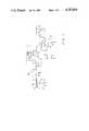
- FIG. 1is a schematic diagram of that portion of the present invention for extracting cardio-pulmonary activity signals from a motion monitor
- FIG. 2is a schematic diagram of that portion of the present invention which responds to the signals developed by the circuit of FIG. 1 and also adjusts the system alarm level as a function of cardiac rate.
- a motion monitor charge transduceris shown generally at 10 and is preferably constructed in accordance with the teaching of applicant's prior U.S. Pat. No. 4,474,185.
- the transducer 10contains an upper conductive electrode or layer 12 and a lower conductive electrostatic shield or layer 14.
- An insulative layer 16separates the upper and lower conductive layers.
- the lower conductive layeris connected to an earth ground through a ferrite bead 18 and a high impedance resistor 20.
- a capacitor 21is connected in parallel with resistor 20.
- the ferrite beadprovides high frequency filtering while the resistor 20 provides a discharge path for accumulated charge on the layer 14.
- Capacitor 21decouples RF signals to ground.
- the active electrode or electrical layer 12is connected through a second ferrite bead 22 to an input terminal of a frequency selective charge amplifier or dual integrator 24.
- a capacitor 23decouples high frequency noise in conjunction with bead 22.
- the amplifier 24includes an operational amplifier 26 having an inverting input terminal to which the signal from layer 12 is connected through high impedance input resistors 28 and 30.
- a capacitor 32 connected between a junction intermediate resistors 28 and 30 and groundoperates in conjunction with the resistors 28 and 30 to provide a high frequency filter.
- the amplifier 26includes an AC feedback loop connected between an output terminal and the inverting input terminal.
- the AC feedback loopincludes first and second serially connected capacitors 34 and 36 with a resistor 38 connecting the junction intermediate the two capacitors to ground.
- a ten picofarad capacitor 40 connected in parallel with the series connection of capacitors 34 and 36prevents high frequency oscillation and is sometimes referred to as a Miller capacitor. It will be appreciated that the circuit as thus far described provides no DC feedback and will thus tend to drift to either the positive or negative rails over time. In order to prevent such drift and to provide for a very fast low frequency roll off, there is included an active feedback network utilizing a second amplifier 42 connected as an operational amplifier for providing DC feedback.
- An output terminal of the amplifier 26is connected through a resistor 44 and resistor 46 to an inverting input terminal of amplifier 42.
- the resistor 44is shunted by two reverse parallel connected diodes 48 and 50 which provide a quasilogarithmic amplifier response to reduce large signal saturation of the amplifier 42.
- the amplifier 42is also connected as an integrator with a relatively long time constant and as such includes a capacitor 52 connected between its output terminal and inverting input terminal.
- a resistor 54connected in series with capacitor 52 sets the AC gain of the amplifier.
- the non-inverting input terminal of amplifier 42is connected to earth ground through the parallel combination of a resistor 56 and capacitor 58.
- An output terminal of amplifier 42is connected to the noninverting input terminal of amplifier 26 through a coupling resistor 60.
- An additional capacitor 62is connected between the noninverting terminal of amplifier 26 and ground to provide suppression of thermal noise generated by the large resistance value resistors.
- the output signal generated by amplifier 42is a quasi-analog feedback signal.
- the output of the charge amplifier 24 of FIG. 1 at terminal Tis primarily the amplified changes in the charge potential on the transducer 10 created by breathing of the person with which the transducer 10 is associated. However, also riding on that signal is a signal of somewhat higher frequency which represents the cardiac rate of the person being monitored.
- the circuit of FIG. 1has been found to be extremely practical in stripping out the extraneous noise signals created by 60 hz power lines and radio station signals and other electronic noise generally available in the atmosphere. In constructing the circuit of FIG. 1, the following values were used, where R represents resistor and C indicates capacitor;
- the arrangement described in FIG. 1thus provides amplification of the breathing and cardiac signals developed by a person associated with the transducer 10 and eliminates all of the extraneous signals in which those breathing and cardiac signals are essentially buried.
- the overall circuithas essentially zero gain for DC and yet has exceedingly high gain between 0.1 hz and 1.5 hz (the fifty per cent attenuation points).
- the roll off rate at the upper frequencyis not as quick as the lower end but does drop off at a rate of about 12 db per octave above about 8 hz.
- the 60 hz. and 50 hz power signalsare inconsequential at the output developed at terminal T.
- the ferrite beads 18 and 22 in combination with capacitors 21 and 23essentially eliminate most of the RF and AM radio station interference. Below 0.01 hz., the circuit has approximately 100 second time constant so that the DC gain rapidly drops to zero below 0.01 hz.
- An important feature of the circuit in FIG. 1is that it is not necessary to decouple the output of the circuit before applying it to a comparator because the circuit automatically zeros itself and long term offset drift of the amplifier is compensated.
- the filtering networkis such that capacitive coupling is required which then requires fairly sophisticated circuitry for low frequency coupling.
- the circuit described aboveprovides the unique features and advantages for detecting the relatively low frequency breathing and cardiac rates of an individual and for excluding extraneous noise signals.
- FIG. 2there is shown a comparator circuit for providing an output signal upon occurrence of each breathing cycle of a patient and an alarm circuit for providing an indication of abnormal breathing. There is also illustrated a circuit for varying the alarm signal level as a function of cardiac activity.
- the terminal T'corresponds to the terminal T of FIG. 1.
- the signal developed by the amplifier 24is coupled through a resistor 64 to an inverting input terminal of a comparator 66.
- the comparator 66includes a high frequency shunt capacitor 68 to further filter any high frequency signals on the breathing signal.
- a bleeder resistor 70provides a discharge path for capacitor 68.
- the noninverting input terminal comparator 66is connected to a voltage divider circuit comprises of first and second resistors 72 and 74 serially connected between a voltage reference V cc and earth ground.
- the values of resistors 72 and 74are selected so as to allow the comparator to trip upon receipt of a signal indicative of motion or breathing of a patient being monitored.
- the output signal developed by the comparator 66is normally at a positive voltage level but switches to a negative voltage level when the input at the inverting input terminal goes positive, that is, when the patient being monitored either breathes or moves.
- the output terminal of comparator 66is connected through a coupling resistor 76 to an LED indicating circuit comprising first and second transistors 78 and 80.
- An LED 82is serially connected between an emitter terminal of transistor 78 and an emitter terminal of transistor 80.
- a collector terminal of transistor 78is connected to the positive voltage source V cc and the collector terminal of transistor 80 is connected to a negative of V ss .
- a capacitor 84is connected between the voltage V ss and one terminal of the LED 82.
- the circuitwill provide an indication corresponding to each event associated with moving or breathing of the patient being monitored.
- the signals developed by the comparator 66are also coupled to an alarm circuit for energizing a pulsating type of alarm such as the Sonalert (trademark of Mallory) alarm which is a piezoelectric type annunciator.
- the signal from comparator 66is coupled through a resistor 86 to an inverting input terminal of a second comparator 88.
- the noninverting input terminal of comparator 88is connected to a reference level established in the block 90 by first and second resistors 92 and 94 serially connected between the voltage source V cc and earth ground. It will be apparent that the comparator 88 may be operated from the fixed reference source 90 or may be operated from the variable reference source established in the block 96.
- Either one or the other of the blocks 90 or 96may be selected but both would not be used simultaneously.
- the block 90is used when the comparison is to be a fixed level and not corrected as a function of cardiac rate. For those instances in which it is desirable to adjust the comparison level as a function of cardiac rate, the circuitry shown in the block 90 is deleted and that circuitry shown in the block 96 is incorporated.
- the comparator 88is set to detect an apnea interval and, as such, the pulses developed by the comparator 66 are accumulated in an integrator comprising the resistor 86 and a capacitor 98.
- the comparator 88in conjunction with resistor 86 and capacitor 98 essentially forms an interval timer.
- the time constant for charging the capacitor 98is set so that the charge on the capacitor 98 will trip the comparator 88 if breathing events do not occur within a predetermined interval such as, for example, 20 seconds.
- the comparator 88is tripped, i.e., when the voltage on capacitor 98 becomes more positive than the voltage on the noninverting input terminal, the output of comparator 88 will slew to a negative voltage level allowing current to flow through the alarm 100 and a serially connected light emitting diode 102.
- the LED 102will glow thereby providing a visual indication of an alarm condition and the alarm 100 will provide an audible indication of an alarm condition.
- a diode 104 connected between the reference voltage source at the noninverting terminal comparator 88 and its output terminalwill be forward biased and will act as a latch to prevent the alarm from being turned off until a manual reset has been performed by deenergizing the unit. This action provides a safety circuit to prevent a reset until someone has been notified of the apnea episode.
- the positive voltage developed by comparator 66charges the capacitor 98 and when the charge reaches a predetermined value causes the comparator 88 to change states.
- the output of comparator 66goes to a negative value.
- the charge on capacitor 98is removed or discharged.
- the dischargeoccurs through resistors 106 and 108 and diode 110.
- a junction intermediate resistors 106 and 108is connected through a capacitor 112 to negative voltage source V ss .
- the capacitor 112provides an initializing current on a restart, i.e., when power is first applied to the system. Without the capacitor 112, the system would automatically go into alarm condition whenever power was applied.
- Capacitor 112forces the comparator 88 inverting input to a negative value to allow it to be initialized with a positive output voltage.
- the input terminal T'is connected to a band pass filter circuit utilizing an operational amplifier 114.
- the inverting input terminal of amplifier 114is connected to terminal T' through a coupling resistor 116 and capacitor 118.
- a capacitor 120connected between an output amplifier 114 and the junction intermediate resistor 116 and capacitor 118 operates in conjunction with those latter elements to set the band pass for the amplifier.
- the resistor 122 connected between the output terminal and the inverting input terminalprovides the DC feedback while a capacitor 124 connected in parallel with resistor 122 prevents high frequency oscillations.
- the noninverting terminal of amp 114is connected through a resistor 126 to earth ground.
- the band pass filteris designed to have a center frequency of about 6.8 hz so as to filter out the pulses caused by breathing of the patient being monitored and to pass only those pulses corresponding to the cardiac activity.
- the cardiac activity pulsesappear as essentially a sinusoidal wave modulating the breathing signals.
- the amplified breathing signalsmay vary in amplitude between 500 millivolts and 2 volts peak-to-peak depending upon the intensity of the breath and the size and orientation of the patient being monitored.
- the cardiac pulsesare in the range of 100 millivolts in amplitude and are superimposed on the pulmonary activity.
- the signals representative of cardiac activityare coupled through a decoupling capacitor 128 and rectifying circuit comprising diodes 130 and 132 and then through a coupling resistor 134 to an inverting input terminal of a comparator 136.
- a filter circuitcomprising a resistor 138 and parallel connected to capacitor 140 are connected between an anode terminal of diode 132 and earth ground.
- the filter circuitacts as an integrator with approximately a one second time constant so that a charge can be developed on the capacitor 140 as the cardiac rate of the patient being monitored increases.
- the output signal developed by the comparator 136will slew to a lower level which may be a negative value and will allow the comparison between the voltage on capacitor 98 and the voltage developed by the output of comparator 88 to be based on a much lower value thereby causing the comparator to trip at a reduced breathing time interval.
- the initial value at which the comparator 136 will tripis set by connecting the noninverting terminal of comparator 136 to a junction intermediate first and second resistors 142 and 144 which are connected as a voltage divider between negative voltage source V ss and earth ground.
- comparator 136The inverting input terminal of comparator 136 is connected through a resistor 146 to positive voltage source V cc whereby the inverting input terminal is normally held at approximately ground potential.
- a capacitor 148connected between the output terminal of comparator 136 and its inverting input terminal provides a high frequency shunt.
- the operational amplifier and comparator circuits used in the arrangement described in FIG. 1 and FIG. 2are of a type well known in the art and available from numerous different manufacturers under different numbers. Although the system has been shown using discreet components, it is apparent that the system could be easily implemented using large scale integrated circuits. Furthermore, although the system has been disclosed as a monitor for cardiopulmonary activity, it will be apparent that the system will detect motion of any type within the general area of the transducer, including motion associated with inanimate objects. It should also be noted that the transducer uses only a single electrode and that the layer 14 operates only as an electrostatic shield.
Landscapes
- Health & Medical Sciences (AREA)
- Life Sciences & Earth Sciences (AREA)
- Heart & Thoracic Surgery (AREA)
- Physiology (AREA)
- General Health & Medical Sciences (AREA)
- Physics & Mathematics (AREA)
- Biophysics (AREA)
- Public Health (AREA)
- Engineering & Computer Science (AREA)
- Biomedical Technology (AREA)
- Pathology (AREA)
- Medical Informatics (AREA)
- Molecular Biology (AREA)
- Surgery (AREA)
- Animal Behavior & Ethology (AREA)
- Veterinary Medicine (AREA)
- Oral & Maxillofacial Surgery (AREA)
- Dentistry (AREA)
- Cardiology (AREA)
- Pulmonology (AREA)
- Physical Education & Sports Medicine (AREA)
- Gerontology & Geriatric Medicine (AREA)
- Business, Economics & Management (AREA)
- Emergency Management (AREA)
- General Physics & Mathematics (AREA)
- Measuring Pulse, Heart Rate, Blood Pressure Or Blood Flow (AREA)
- Measurement Of The Respiration, Hearing Ability, Form, And Blood Characteristics Of Living Organisms (AREA)
- Measurement And Recording Of Electrical Phenomena And Electrical Characteristics Of The Living Body (AREA)
- Measuring And Recording Apparatus For Diagnosis (AREA)
- Investigating Or Analysing Biological Materials (AREA)
- Medicines Containing Antibodies Or Antigens For Use As Internal Diagnostic Agents (AREA)
- Measurement Of Mechanical Vibrations Or Ultrasonic Waves (AREA)
- Electrotherapy Devices (AREA)
Abstract
Description
______________________________________ Ohms ______________________________________ R.sub.28 10 M R.sub.30 1 M R.sub.38 1 M R.sub.44 10 M R.sub.46 4.7 M R.sub.54 1 K R.sub.56 10 M R.sub.60 10 M R.sub.20 10 M C.sub.21 0.001 uf C.sub.23 0.001 uf C.sub.32 .01 uf C.sub.34 .001 uf C.sub.36 .001 uf C.sub.40 10 pf C.sub.52 10 uf C.sub.58 .01 uf C.sub.62 .01 uf D.sub.48 1N914 D.sub.50 1N914 ______________________________________
______________________________________ Ohms ______________________________________ R.sub.64 10 k R 10 M R.sub.72 10 M R.sub.74 100 k R.sub.76 10 k R.sub.86 10 M R.sub.92 1 M R.sub.94 10 M R.sub.106 10 k R.sub.10 47 k R.sub.116 4.7 k R.sub.122 10 M R.sub.126 10 M R.sub.138 10 M R.sub.134 100 k R.sub.146 10 M R.sub.142 10 M R.sub.144 1 M C.sub.68 .01 uf C.sub.84 100 uf C.sub.112 .01 uf C.sub.98 .47 uf C.sub.118 .047 uf C.sub.120 .22 uf C.sub.124 370 pf C.sub.128 .1 uf C.sub.140 .1 uf C.sub.148 .01 uf ______________________________________
Claims (15)
Priority Applications (9)
| Application Number | Priority Date | Filing Date | Title |
|---|---|---|---|
| US06/794,492US4757825A (en) | 1985-10-31 | 1985-10-31 | Cardio-pulmonary activity monitor |
| DE3689929TDE3689929D1 (en) | 1985-10-31 | 1986-10-01 | Movement monitor for cardiopulmonary activity and the like. |
| EP86307537AEP0222484B1 (en) | 1985-10-31 | 1986-10-01 | Movement monitor for cardio-pulmonary and other activity |
| AT86307537TATE107491T1 (en) | 1985-10-31 | 1986-10-01 | MOTION MONITOR FOR CARDIAC LUNG ACTIVITY AND SIMILAR. |
| AU64138/86AAU594982B2 (en) | 1985-10-31 | 1986-10-17 | Movement monitor for cardio-pulmonary and other activity |
| BR8605346ABR8605346A (en) | 1985-10-31 | 1986-10-30 | PROCESS TO PROVIDE AN INDICATION OF CARDIOPULMONARY ACTIVITY, APPARATUS TO MONITOR THE SAME AND MOVEMENT DETECTOR OF THE TYPE INCLUDING AN ELECTROSTATIC LOAD COLLECTOR |
| KR1019860009124AKR940011205B1 (en) | 1985-10-31 | 1986-10-30 | Cardiopulmonary Activity Monitor Device |
| IL80465AIL80465A0 (en) | 1985-10-31 | 1986-10-31 | Movement monitor for cardio-pulmonary and other activity |
| JP61258716AJPH0755221B2 (en) | 1985-10-31 | 1986-10-31 | Activity monitor for cardiopulmonary and other activities |
Applications Claiming Priority (1)
| Application Number | Priority Date | Filing Date | Title |
|---|---|---|---|
| US06/794,492US4757825A (en) | 1985-10-31 | 1985-10-31 | Cardio-pulmonary activity monitor |
Publications (1)
| Publication Number | Publication Date |
|---|---|
| US4757825Atrue US4757825A (en) | 1988-07-19 |
Family
ID=25162784
Family Applications (1)
| Application Number | Title | Priority Date | Filing Date |
|---|---|---|---|
| US06/794,492Expired - Fee RelatedUS4757825A (en) | 1985-10-31 | 1985-10-31 | Cardio-pulmonary activity monitor |
Country Status (9)
| Country | Link |
|---|---|
| US (1) | US4757825A (en) |
| EP (1) | EP0222484B1 (en) |
| JP (1) | JPH0755221B2 (en) |
| KR (1) | KR940011205B1 (en) |
| AT (1) | ATE107491T1 (en) |
| AU (1) | AU594982B2 (en) |
| BR (1) | BR8605346A (en) |
| DE (1) | DE3689929D1 (en) |
| IL (1) | IL80465A0 (en) |
Cited By (49)
| Publication number | Priority date | Publication date | Assignee | Title |
|---|---|---|---|---|
| US5044366A (en)* | 1986-09-12 | 1991-09-03 | Intermedics, Inc. | Rate responsive cardiac pacemaker |
| US5101831A (en)* | 1989-07-07 | 1992-04-07 | Matsushita Electric Works, Ltd. | System for discriminating sleep state |
| US5928133A (en)* | 1997-01-30 | 1999-07-27 | Halyak; George | User responsive sleep monitoring and awakening device |
| US6335962B1 (en)* | 1998-03-27 | 2002-01-01 | Lucent Technologies Inc. | Apparatus and method for grouping and prioritizing voice messages for convenient playback |
| WO2001054563A3 (en)* | 2000-01-31 | 2002-04-04 | Integrated Biosensing Technolo | Method and apparatus for biopotential sensing and stimulation |
| US6375621B1 (en) | 1987-03-06 | 2002-04-23 | Ocean Laboratories, Inc. | Passive apnea monitor |
| US6434420B1 (en) | 2000-01-31 | 2002-08-13 | Integrated Biosensing Technologies | Biopotential electrode sensory component |
| US6434421B1 (en)* | 2000-01-31 | 2002-08-13 | Integrated Biosensing Technologies | Biopotential sensor electrode |
| US6438413B1 (en)* | 2000-01-31 | 2002-08-20 | Integrated Biosensing Technologies | Biopotential sensor electrode system |
| US6571599B1 (en)* | 1995-07-03 | 2003-06-03 | Resmed Limited | Auto-calibration of pressure transducer offset |
| US6765489B1 (en) | 2002-08-12 | 2004-07-20 | Milwaukee Electronics Corporation | Accelerometer-based infant movement monitoring and alarm device |
| US20040194220A1 (en)* | 1998-10-28 | 2004-10-07 | Hill-Rom Services, Inc. | Force optimization surface apparatus and method |
| RU2254804C2 (en)* | 2003-07-28 | 2005-06-27 | Северный государственный медицинский университет (СГМУ) | Method for evaluating altered conjugation of cardiohemodynamics and external respiration |
| US6984207B1 (en) | 1999-09-14 | 2006-01-10 | Hoana Medical, Inc. | Passive physiological monitoring (P2M) system |
| US20060224076A1 (en)* | 2004-02-05 | 2006-10-05 | Earlysense Ltd. | Techniques for prediction and monitoring of respiration-manifested clinical episodes |
| US20070118054A1 (en)* | 2005-11-01 | 2007-05-24 | Earlysense Ltd. | Methods and systems for monitoring patients for clinical episodes |
| US20070208235A1 (en)* | 1993-09-04 | 2007-09-06 | Marcus Besson | Wireless medical diagnosis and monitoring equipment |
| US20070291962A1 (en)* | 2006-05-26 | 2007-12-20 | Watson Alan R | Automotive balanced microphone system and method of forming same |
| US20080039739A1 (en)* | 2006-08-14 | 2008-02-14 | Buja Frederick J | System and method employing a thermocouple junction for monitoring of physiological parameters |
| WO2007117402A3 (en)* | 2006-04-01 | 2008-05-02 | Us Gov Sec Army | Human biovibrations method |
| US20080208063A1 (en)* | 2005-06-07 | 2008-08-28 | Koninklijke Philips Electronics N. V. | Patient Monitoring System and Method |
| US20080269625A1 (en)* | 2004-02-05 | 2008-10-30 | Earlysense Ltd. | Prediction and monitoring of clinical episodes |
| US20080275349A1 (en)* | 2007-05-02 | 2008-11-06 | Earlysense Ltd. | Monitoring, predicting and treating clinical episodes |
| WO2009124297A1 (en)* | 2008-04-03 | 2009-10-08 | Kai Sensors, Inc. | Non-contact physiologic motion sensors and methods for use |
| US7666151B2 (en) | 2002-11-20 | 2010-02-23 | Hoana Medical, Inc. | Devices and methods for passive patient monitoring |
| US20100101022A1 (en)* | 2008-10-24 | 2010-04-29 | Carl William Riley | Apparatuses for supporting and monitoring a person |
| US20100240999A1 (en)* | 2008-04-03 | 2010-09-23 | Kai Medical, Inc. | Systems and methods for point in time measurement of physiologic motion |
| US20110046498A1 (en)* | 2007-05-02 | 2011-02-24 | Earlysense Ltd | Monitoring, predicting and treating clinical episodes |
| US20110068935A1 (en)* | 2009-09-18 | 2011-03-24 | Riley Carl W | Apparatuses for supporting and monitoring a condition of a person |
| CN102046076A (en)* | 2008-04-03 | 2011-05-04 | Kai医药公司 | Non-contact physiological motion sensor and method of use thereof |
| US20110112442A1 (en)* | 2007-05-02 | 2011-05-12 | Earlysense Ltd. | Monitoring, Predicting and Treating Clinical Episodes |
| US20110144455A1 (en)* | 2007-08-31 | 2011-06-16 | Bam Labs, Inc. | Systems and methods for monitoring a subject at rest |
| CN102423261A (en)* | 2011-09-20 | 2012-04-25 | 中国人民解放军第四军医大学 | Ultra-wide bandwidth radar type non-contact life parameter real-time monitoring system |
| US8491492B2 (en) | 2004-02-05 | 2013-07-23 | Earlysense Ltd. | Monitoring a condition of a subject |
| US8752220B2 (en) | 2009-07-10 | 2014-06-17 | Hill-Rom Services, Inc. | Systems for patient support, monitoring and treatment |
| US8844073B2 (en) | 2010-06-07 | 2014-09-30 | Hill-Rom Services, Inc. | Apparatus for supporting and monitoring a person |
| US8882684B2 (en) | 2008-05-12 | 2014-11-11 | Earlysense Ltd. | Monitoring, predicting and treating clinical episodes |
| US8942779B2 (en) | 2004-02-05 | 2015-01-27 | Early Sense Ltd. | Monitoring a condition of a subject |
| US9165449B2 (en) | 2012-05-22 | 2015-10-20 | Hill-Rom Services, Inc. | Occupant egress prediction systems, methods and devices |
| CN105362017A (en)* | 2015-11-23 | 2016-03-02 | 许仕林 | Wireless breathing monitoring mattress for old people |
| US9333136B2 (en) | 2013-02-28 | 2016-05-10 | Hill-Rom Services, Inc. | Sensors in a mattress cover |
| US9532721B2 (en) | 2010-08-06 | 2017-01-03 | The United States Of America As Represented By The Secretary Of The Army | Patient care recommendation system |
| US9552460B2 (en) | 2009-09-18 | 2017-01-24 | Hill-Rom Services, Inc. | Apparatus for supporting and monitoring a person |
| US9861550B2 (en) | 2012-05-22 | 2018-01-09 | Hill-Rom Services, Inc. | Adverse condition detection, assessment, and response systems, methods and devices |
| US9883809B2 (en) | 2008-05-01 | 2018-02-06 | Earlysense Ltd. | Monitoring, predicting and treating clinical episodes |
| US10292625B2 (en) | 2010-12-07 | 2019-05-21 | Earlysense Ltd. | Monitoring a sleeping subject |
| US11172892B2 (en) | 2017-01-04 | 2021-11-16 | Hill-Rom Services, Inc. | Patient support apparatus having vital signs monitoring and alerting |
| US11350849B2 (en) | 2010-05-14 | 2022-06-07 | Resmed Sensor Technologies Limited | Systems and methods for non-contact multiparameter vital signs monitoring, apnea therapy, apnea diagnosis, and snore therapy |
| US11844605B2 (en) | 2016-11-10 | 2023-12-19 | The Research Foundation For Suny | System, method and biomarkers for airway obstruction |
Families Citing this family (4)
| Publication number | Priority date | Publication date | Assignee | Title |
|---|---|---|---|---|
| FR2631478B1 (en)* | 1988-05-13 | 1992-09-04 | Heil Helga | SURVEILLANCE WAVES |
| DE69210697T2 (en)* | 1991-07-19 | 1996-11-28 | Philips Electronics Nv | Iron with motion sensor |
| FR2722676A1 (en)* | 1994-07-21 | 1996-01-26 | Stephanois Rech Mec | DEVICE FOR MEASURING PHYSIOLOGICAL PARAMETERS OF A LIVING BEING |
| GB2354823A (en)* | 1999-05-25 | 2001-04-04 | Univ Cardiff | Device for identifying a trend indicative of an abnormal physiological condition |
Citations (12)
| Publication number | Priority date | Publication date | Assignee | Title |
|---|---|---|---|---|
| US32180A (en)* | 1861-04-30 | Halter-king | ||
| US2614144A (en)* | 1948-06-26 | 1952-10-14 | Gulton Mfg Corp | Transducer element and method of making same |
| DE2527475A1 (en)* | 1975-06-20 | 1976-12-30 | Hellige Gmbh | Automatic monitoring equipment for e.g. respiration heart rate - with automatically adjusting threshold value discriminator for preselected comparative value ratio |
| US4169462A (en)* | 1977-05-19 | 1979-10-02 | Strube Richard E | Crib death detector |
| DE2829269A1 (en)* | 1978-07-04 | 1980-01-17 | Hennig | METHOD FOR DETERMINING CARDIOLOGICAL MEASUREMENTS AND DEVICE FOR IMPLEMENTING THE METHOD |
| US4289142A (en)* | 1978-11-24 | 1981-09-15 | Kearns Kenneth L | Physiological occurrence, such as apnea, monitor and X-ray triggering device |
| US4320766A (en)* | 1979-03-13 | 1982-03-23 | Instrumentarium Oy | Apparatus in medicine for the monitoring and or recording of the body movements of a person on a bed, for instance of a patient |
| US4381788A (en)* | 1981-02-27 | 1983-05-03 | Douglas David W | Method and apparatus for detecting apnea |
| US4387722A (en)* | 1978-11-24 | 1983-06-14 | Kearns Kenneth L | Respiration monitor and x-ray triggering apparatus |
| US4438771A (en)* | 1982-04-26 | 1984-03-27 | University Of Virginia Alumni Patents Foundation | Passive contactless monitor for detecting cessation of cardiopulmonary |
| US4509527A (en)* | 1983-04-08 | 1985-04-09 | Timex Medical Products Corporation | Cardio-respiration transducer |
| USRE32180E (en) | 1980-02-12 | 1986-06-10 | Composite sheets constituting electromechanical transducers and transducers equipped with such sheets |
Family Cites Families (9)
| Publication number | Priority date | Publication date | Assignee | Title |
|---|---|---|---|---|
| US4033332A (en)* | 1972-09-11 | 1977-07-05 | Cavitron Corporation | Activity and respiration monitor |
| US3926177A (en)* | 1972-09-11 | 1975-12-16 | Cavitron Corp | Activity and respiration monitor |
| US3996922A (en)* | 1973-08-17 | 1976-12-14 | Electronic Monitors, Inc. | Flexible force responsive transducer |
| US3973208A (en) | 1975-02-14 | 1976-08-03 | Dovey Manufacturing Company | Capacitor detector device |
| FI59718C (en)* | 1979-03-13 | 1981-10-12 | Instrumentarium Oy | FOERFARANDE INOM LAEKARVETENSKAPEN FOER OEVERVAKNING OCH / ELLER REGISTRERING AV EN PAO EN SAENG LIGGANDE PERSONS T EX EN PATIENTS KROPPSROERELSER |
| AU7391781A (en)* | 1980-08-08 | 1983-10-20 | Harry Clark McIlwraith | Detection and monitoring movement |
| US4503705A (en)* | 1982-02-24 | 1985-03-12 | The Langer Biomechanics Group, Inc. | Flexible force sensor |
| US4474185A (en) | 1982-05-12 | 1984-10-02 | Diamond Donald A | Body movement detector |
| US4484043A (en)* | 1982-09-30 | 1984-11-20 | Bed-Check Corporation | Switch apparatus responsive to pressure or distortion |
- 1985
- 1985-10-31USUS06/794,492patent/US4757825A/ennot_activeExpired - Fee Related
- 1986
- 1986-10-01EPEP86307537Apatent/EP0222484B1/ennot_activeExpired - Lifetime
- 1986-10-01ATAT86307537Tpatent/ATE107491T1/enactive
- 1986-10-01DEDE3689929Tpatent/DE3689929D1/ennot_activeExpired - Lifetime
- 1986-10-17AUAU64138/86Apatent/AU594982B2/ennot_activeCeased
- 1986-10-30KRKR1019860009124Apatent/KR940011205B1/ennot_activeExpired - Fee Related
- 1986-10-30BRBR8605346Apatent/BR8605346A/ennot_activeApplication Discontinuation
- 1986-10-31JPJP61258716Apatent/JPH0755221B2/ennot_activeExpired - Lifetime
- 1986-10-31ILIL80465Apatent/IL80465A0/enunknown
Patent Citations (12)
| Publication number | Priority date | Publication date | Assignee | Title |
|---|---|---|---|---|
| US32180A (en)* | 1861-04-30 | Halter-king | ||
| US2614144A (en)* | 1948-06-26 | 1952-10-14 | Gulton Mfg Corp | Transducer element and method of making same |
| DE2527475A1 (en)* | 1975-06-20 | 1976-12-30 | Hellige Gmbh | Automatic monitoring equipment for e.g. respiration heart rate - with automatically adjusting threshold value discriminator for preselected comparative value ratio |
| US4169462A (en)* | 1977-05-19 | 1979-10-02 | Strube Richard E | Crib death detector |
| DE2829269A1 (en)* | 1978-07-04 | 1980-01-17 | Hennig | METHOD FOR DETERMINING CARDIOLOGICAL MEASUREMENTS AND DEVICE FOR IMPLEMENTING THE METHOD |
| US4289142A (en)* | 1978-11-24 | 1981-09-15 | Kearns Kenneth L | Physiological occurrence, such as apnea, monitor and X-ray triggering device |
| US4387722A (en)* | 1978-11-24 | 1983-06-14 | Kearns Kenneth L | Respiration monitor and x-ray triggering apparatus |
| US4320766A (en)* | 1979-03-13 | 1982-03-23 | Instrumentarium Oy | Apparatus in medicine for the monitoring and or recording of the body movements of a person on a bed, for instance of a patient |
| USRE32180E (en) | 1980-02-12 | 1986-06-10 | Composite sheets constituting electromechanical transducers and transducers equipped with such sheets | |
| US4381788A (en)* | 1981-02-27 | 1983-05-03 | Douglas David W | Method and apparatus for detecting apnea |
| US4438771A (en)* | 1982-04-26 | 1984-03-27 | University Of Virginia Alumni Patents Foundation | Passive contactless monitor for detecting cessation of cardiopulmonary |
| US4509527A (en)* | 1983-04-08 | 1985-04-09 | Timex Medical Products Corporation | Cardio-respiration transducer |
Cited By (103)
| Publication number | Priority date | Publication date | Assignee | Title |
|---|---|---|---|---|
| US5044366A (en)* | 1986-09-12 | 1991-09-03 | Intermedics, Inc. | Rate responsive cardiac pacemaker |
| US6375621B1 (en) | 1987-03-06 | 2002-04-23 | Ocean Laboratories, Inc. | Passive apnea monitor |
| US5101831A (en)* | 1989-07-07 | 1992-04-07 | Matsushita Electric Works, Ltd. | System for discriminating sleep state |
| US8771184B2 (en) | 1993-09-04 | 2014-07-08 | Body Science Llc | Wireless medical diagnosis and monitoring equipment |
| US20070208235A1 (en)* | 1993-09-04 | 2007-09-06 | Marcus Besson | Wireless medical diagnosis and monitoring equipment |
| US6571599B1 (en)* | 1995-07-03 | 2003-06-03 | Resmed Limited | Auto-calibration of pressure transducer offset |
| US5928133A (en)* | 1997-01-30 | 1999-07-27 | Halyak; George | User responsive sleep monitoring and awakening device |
| US6335962B1 (en)* | 1998-03-27 | 2002-01-01 | Lucent Technologies Inc. | Apparatus and method for grouping and prioritizing voice messages for convenient playback |
| US7515059B2 (en) | 1998-10-28 | 2009-04-07 | Hill-Rom Services, Inc. | Patient support surface with physiological sensors |
| US7330127B2 (en)* | 1998-10-28 | 2008-02-12 | Hill-Rom Services, Inc. | Force optimization surface apparatus and method |
| US20090183312A1 (en)* | 1998-10-28 | 2009-07-23 | Price James H | Patient support surface with vital signs sensors |
| US20040194220A1 (en)* | 1998-10-28 | 2004-10-07 | Hill-Rom Services, Inc. | Force optimization surface apparatus and method |
| US8031080B2 (en) | 1998-10-28 | 2011-10-04 | Hill-Rom Services, Inc. | Patient support surface with vital signs sensors |
| US20080060138A1 (en)* | 1998-10-28 | 2008-03-13 | Price James H | Patient support surface with physiological sensors |
| US6984207B1 (en) | 1999-09-14 | 2006-01-10 | Hoana Medical, Inc. | Passive physiological monitoring (P2M) system |
| US20060063982A1 (en)* | 1999-09-14 | 2006-03-23 | Hoana Medical, Inc. | Passive physiological monitoring (P2M) system |
| US6438413B1 (en)* | 2000-01-31 | 2002-08-20 | Integrated Biosensing Technologies | Biopotential sensor electrode system |
| US6434420B1 (en) | 2000-01-31 | 2002-08-13 | Integrated Biosensing Technologies | Biopotential electrode sensory component |
| WO2001054563A3 (en)* | 2000-01-31 | 2002-04-04 | Integrated Biosensing Technolo | Method and apparatus for biopotential sensing and stimulation |
| US6434421B1 (en)* | 2000-01-31 | 2002-08-13 | Integrated Biosensing Technologies | Biopotential sensor electrode |
| US6765489B1 (en) | 2002-08-12 | 2004-07-20 | Milwaukee Electronics Corporation | Accelerometer-based infant movement monitoring and alarm device |
| US7666151B2 (en) | 2002-11-20 | 2010-02-23 | Hoana Medical, Inc. | Devices and methods for passive patient monitoring |
| RU2254804C2 (en)* | 2003-07-28 | 2005-06-27 | Северный государственный медицинский университет (СГМУ) | Method for evaluating altered conjugation of cardiohemodynamics and external respiration |
| US20110015535A1 (en)* | 2004-02-05 | 2011-01-20 | Earlysense Ltd. | Techniques for prediction and monitoring of coughing-manifested clinical episodes |
| US8731646B2 (en) | 2004-02-05 | 2014-05-20 | Earlysense Ltd. | Prediction and monitoring of clinical episodes |
| US8942779B2 (en) | 2004-02-05 | 2015-01-27 | Early Sense Ltd. | Monitoring a condition of a subject |
| US8840564B2 (en) | 2004-02-05 | 2014-09-23 | Early Sense Ltd. | Monitoring a condition of a subject |
| US8376954B2 (en) | 2004-02-05 | 2013-02-19 | Earlysense Ltd. | Techniques for prediction and monitoring of respiration-manifested clinical episodes |
| US20060224076A1 (en)* | 2004-02-05 | 2006-10-05 | Earlysense Ltd. | Techniques for prediction and monitoring of respiration-manifested clinical episodes |
| US20080269625A1 (en)* | 2004-02-05 | 2008-10-30 | Earlysense Ltd. | Prediction and monitoring of clinical episodes |
| US8992434B2 (en) | 2004-02-05 | 2015-03-31 | Earlysense Ltd. | Prediction and monitoring of clinical episodes |
| US9131902B2 (en) | 2004-02-05 | 2015-09-15 | Earlysense Ltd. | Prediction and monitoring of clinical episodes |
| US8679030B2 (en) | 2004-02-05 | 2014-03-25 | Earlysense Ltd. | Monitoring a condition of a subject |
| US8603010B2 (en) | 2004-02-05 | 2013-12-10 | Earlysense Ltd. | Techniques for prediction and monitoring of clinical episodes |
| US8517953B2 (en) | 2004-02-05 | 2013-08-27 | Earlysense Ltd. | Techniques for prediction and monitoring of coughing-manifested clinical episodes |
| US8491492B2 (en) | 2004-02-05 | 2013-07-23 | Earlysense Ltd. | Monitoring a condition of a subject |
| US8403865B2 (en) | 2004-02-05 | 2013-03-26 | Earlysense Ltd. | Prediction and monitoring of clinical episodes |
| US9788791B2 (en)* | 2005-06-07 | 2017-10-17 | Koninklijke Philips N.V. | Patient monitoring system and method |
| US20080208063A1 (en)* | 2005-06-07 | 2008-08-28 | Koninklijke Philips Electronics N. V. | Patient Monitoring System and Method |
| US9026199B2 (en) | 2005-11-01 | 2015-05-05 | Earlysense Ltd. | Monitoring a condition of a subject |
| US20070118054A1 (en)* | 2005-11-01 | 2007-05-24 | Earlysense Ltd. | Methods and systems for monitoring patients for clinical episodes |
| US20090149779A1 (en)* | 2006-04-01 | 2009-06-11 | Russo Michael B | Human Biovibrations Method |
| WO2007117402A3 (en)* | 2006-04-01 | 2008-05-02 | Us Gov Sec Army | Human biovibrations method |
| US8273035B2 (en) | 2006-04-01 | 2012-09-25 | The United States Of America As Represented By The Secretary Of The Army | Human biovibrations method |
| WO2007140361A3 (en)* | 2006-05-26 | 2008-11-06 | Gentex Corp | Automotive balanced microphone system and method of forming same |
| US20070291962A1 (en)* | 2006-05-26 | 2007-12-20 | Watson Alan R | Automotive balanced microphone system and method of forming same |
| US9615752B2 (en)* | 2006-08-14 | 2017-04-11 | Frederick J. Buja | System and method employing a thermocouple junction for monitoring of physiological parameters |
| US20150025331A1 (en)* | 2006-08-14 | 2015-01-22 | Frederick J. Buja | System and method employing a thermocouple junction for monitoring of physiological parameters |
| US8790256B2 (en)* | 2006-08-14 | 2014-07-29 | Frederick J. Buja | System and method employing a thermocouple junction for monitoring of physiological parameters |
| US20080039739A1 (en)* | 2006-08-14 | 2008-02-14 | Buja Frederick J | System and method employing a thermocouple junction for monitoring of physiological parameters |
| US8585607B2 (en) | 2007-05-02 | 2013-11-19 | Earlysense Ltd. | Monitoring, predicting and treating clinical episodes |
| US20080275349A1 (en)* | 2007-05-02 | 2008-11-06 | Earlysense Ltd. | Monitoring, predicting and treating clinical episodes |
| US8821418B2 (en) | 2007-05-02 | 2014-09-02 | Earlysense Ltd. | Monitoring, predicting and treating clinical episodes |
| US8734360B2 (en) | 2007-05-02 | 2014-05-27 | Earlysense Ltd. | Monitoring, predicting and treating clinical episodes |
| US20110046498A1 (en)* | 2007-05-02 | 2011-02-24 | Earlysense Ltd | Monitoring, predicting and treating clinical episodes |
| US20110112442A1 (en)* | 2007-05-02 | 2011-05-12 | Earlysense Ltd. | Monitoring, Predicting and Treating Clinical Episodes |
| US20110144455A1 (en)* | 2007-08-31 | 2011-06-16 | Bam Labs, Inc. | Systems and methods for monitoring a subject at rest |
| US20100240999A1 (en)* | 2008-04-03 | 2010-09-23 | Kai Medical, Inc. | Systems and methods for point in time measurement of physiologic motion |
| US8454528B2 (en) | 2008-04-03 | 2013-06-04 | Kai Medical, Inc. | Non-contact physiologic motion sensors and methods for use |
| US20100292568A1 (en)* | 2008-04-03 | 2010-11-18 | Kai Medical, Inc. | Systems and methods for measurement of depth of breath and paradoxical breathing |
| WO2009124297A1 (en)* | 2008-04-03 | 2009-10-08 | Kai Sensors, Inc. | Non-contact physiologic motion sensors and methods for use |
| US20100249633A1 (en)* | 2008-04-03 | 2010-09-30 | Kai Medical, Inc. | Systems and methods for determining regularity of respiration |
| US20100249630A1 (en)* | 2008-04-03 | 2010-09-30 | Kai Medical, Inc. | Systems and methods for respiratory rate measurement |
| CN102046076A (en)* | 2008-04-03 | 2011-05-04 | Kai医药公司 | Non-contact physiological motion sensor and method of use thereof |
| US20100130873A1 (en)* | 2008-04-03 | 2010-05-27 | Kai Sensors, Inc. | Non-contact physiologic motion sensors and methods for use |
| US9883809B2 (en) | 2008-05-01 | 2018-02-06 | Earlysense Ltd. | Monitoring, predicting and treating clinical episodes |
| US8998830B2 (en) | 2008-05-12 | 2015-04-07 | Earlysense Ltd. | Monitoring, predicting and treating clinical episodes |
| US8882684B2 (en) | 2008-05-12 | 2014-11-11 | Earlysense Ltd. | Monitoring, predicting and treating clinical episodes |
| US20100101022A1 (en)* | 2008-10-24 | 2010-04-29 | Carl William Riley | Apparatuses for supporting and monitoring a person |
| US8281433B2 (en) | 2008-10-24 | 2012-10-09 | Hill-Rom Services, Inc. | Apparatuses for supporting and monitoring a person |
| US8752220B2 (en) | 2009-07-10 | 2014-06-17 | Hill-Rom Services, Inc. | Systems for patient support, monitoring and treatment |
| US8525679B2 (en) | 2009-09-18 | 2013-09-03 | Hill-Rom Services, Inc. | Sensor control for apparatuses for supporting and monitoring a person |
| US9549705B2 (en) | 2009-09-18 | 2017-01-24 | Hill-Rom Services, Inc. | Apparatuses for supporting and monitoring a condition of a person |
| US9013315B2 (en) | 2009-09-18 | 2015-04-21 | Hill-Rom Services, Inc. | Sensor control for apparatuses for supporting and monitoring a person |
| US20110068928A1 (en)* | 2009-09-18 | 2011-03-24 | Riley Carl W | Sensor control for apparatuses for supporting and monitoring a person |
| US9044204B2 (en) | 2009-09-18 | 2015-06-02 | Hill-Rom Services, Inc. | Apparatuses for supporting and monitoring a condition of a person |
| US20110068935A1 (en)* | 2009-09-18 | 2011-03-24 | Riley Carl W | Apparatuses for supporting and monitoring a condition of a person |
| US9775758B2 (en) | 2009-09-18 | 2017-10-03 | Hill-Rom Services, Inc. | Person support apparatus having physiological sensor |
| US8525680B2 (en) | 2009-09-18 | 2013-09-03 | Hill-Rom Services, Inc. | Apparatuses for supporting and monitoring a condition of a person |
| US10583058B2 (en) | 2009-09-18 | 2020-03-10 | Hill-Rom Services, Inc. | Person support apparatus having physiological sensor |
| US10111794B2 (en) | 2009-09-18 | 2018-10-30 | Hill-Rom Services, Inc. | Person support apparatus having physiological sensor |
| US9549675B2 (en) | 2009-09-18 | 2017-01-24 | Hill-Rom Services, Inc. | Sensor control for apparatuses for supporting and monitoring a person |
| US9552460B2 (en) | 2009-09-18 | 2017-01-24 | Hill-Rom Services, Inc. | Apparatus for supporting and monitoring a person |
| US11350849B2 (en) | 2010-05-14 | 2022-06-07 | Resmed Sensor Technologies Limited | Systems and methods for non-contact multiparameter vital signs monitoring, apnea therapy, apnea diagnosis, and snore therapy |
| US8844073B2 (en) | 2010-06-07 | 2014-09-30 | Hill-Rom Services, Inc. | Apparatus for supporting and monitoring a person |
| US10383526B2 (en) | 2010-08-06 | 2019-08-20 | United States Government As Represented By The Secretary Of The Army | Patient care recommendation system |
| US9532721B2 (en) | 2010-08-06 | 2017-01-03 | The United States Of America As Represented By The Secretary Of The Army | Patient care recommendation system |
| US11147476B2 (en) | 2010-12-07 | 2021-10-19 | Hill-Rom Services, Inc. | Monitoring a sleeping subject |
| US10292625B2 (en) | 2010-12-07 | 2019-05-21 | Earlysense Ltd. | Monitoring a sleeping subject |
| CN102423261A (en)* | 2011-09-20 | 2012-04-25 | 中国人民解放军第四军医大学 | Ultra-wide bandwidth radar type non-contact life parameter real-time monitoring system |
| CN102423261B (en)* | 2011-09-20 | 2013-10-02 | 中国人民解放军第四军医大学 | Ultra-wide bandwidth radar type non-contact life parameter real-time monitoring system |
| US9761109B2 (en) | 2012-05-22 | 2017-09-12 | Hill-Rom Services, Inc. | Occupant egress prediction systems, methods and devices |
| US9978244B2 (en) | 2012-05-22 | 2018-05-22 | Hill-Rom Services, Inc. | Occupant falls risk determination systems, methods and devices |
| US9861550B2 (en) | 2012-05-22 | 2018-01-09 | Hill-Rom Services, Inc. | Adverse condition detection, assessment, and response systems, methods and devices |
| US9552714B2 (en) | 2012-05-22 | 2017-01-24 | Hill-Rom Services, Inc. | Occupant egress prediction systems, methods and devices |
| US11322258B2 (en) | 2012-05-22 | 2022-05-03 | Hill-Rom Services, Inc. | Adverse condition detection, assessment, and response systems, methods and devices |
| US9165449B2 (en) | 2012-05-22 | 2015-10-20 | Hill-Rom Services, Inc. | Occupant egress prediction systems, methods and devices |
| US9333136B2 (en) | 2013-02-28 | 2016-05-10 | Hill-Rom Services, Inc. | Sensors in a mattress cover |
| US11684529B2 (en) | 2013-02-28 | 2023-06-27 | Hill-Rom Services, Inc. | Mattress cover sensor method |
| CN105362017A (en)* | 2015-11-23 | 2016-03-02 | 许仕林 | Wireless breathing monitoring mattress for old people |
| US11844605B2 (en) | 2016-11-10 | 2023-12-19 | The Research Foundation For Suny | System, method and biomarkers for airway obstruction |
| US11172892B2 (en) | 2017-01-04 | 2021-11-16 | Hill-Rom Services, Inc. | Patient support apparatus having vital signs monitoring and alerting |
| US11896406B2 (en) | 2017-01-04 | 2024-02-13 | Hill-Rom Services, Inc. | Patient support apparatus having vital signs monitoring and alerting |
Also Published As
| Publication number | Publication date |
|---|---|
| BR8605346A (en) | 1987-08-04 |
| EP0222484A3 (en) | 1988-08-03 |
| IL80465A0 (en) | 1987-01-30 |
| KR870003756A (en) | 1987-05-04 |
| JPS62176432A (en) | 1987-08-03 |
| EP0222484A2 (en) | 1987-05-20 |
| AU6413886A (en) | 1987-05-07 |
| ATE107491T1 (en) | 1994-07-15 |
| AU594982B2 (en) | 1990-03-22 |
| EP0222484B1 (en) | 1994-06-22 |
| DE3689929D1 (en) | 1994-07-28 |
| JPH0755221B2 (en) | 1995-06-14 |
| KR940011205B1 (en) | 1994-11-29 |
Similar Documents
| Publication | Publication Date | Title |
|---|---|---|
| US4757825A (en) | Cardio-pulmonary activity monitor | |
| US4474185A (en) | Body movement detector | |
| US3926177A (en) | Activity and respiration monitor | |
| US4033332A (en) | Activity and respiration monitor | |
| US4438771A (en) | Passive contactless monitor for detecting cessation of cardiopulmonary | |
| US3760794A (en) | Respiration monitoring apparatus and method | |
| US4971065A (en) | Transducer for detecting apnea | |
| US4197856A (en) | Ultrasonic respiration/convulsion monitoring apparatus and method for its use | |
| US4306567A (en) | Detection and monitoring device | |
| US4895160A (en) | Apparatus for measuring the life functions of a human being, particularly an infant | |
| US4365636A (en) | Method of monitoring patient respiration and predicting apnea therefrom | |
| US3996922A (en) | Flexible force responsive transducer | |
| US3572317A (en) | Respiratory distress monitor | |
| US6011477A (en) | Respiration and movement monitoring system | |
| US3898981A (en) | Respiration monitoring apparatus | |
| JP2959376B2 (en) | Monitoring device | |
| US3324848A (en) | Capacitance respirometer | |
| EP0073240A1 (en) | Method and apparatus for detecting apnea | |
| US3612041A (en) | Apparatus for detecting ventricular fibrillation | |
| JP2001070256A (en) | Biological monitoring system | |
| US5069221A (en) | Displacement sensor and medical apparatus | |
| WO1999004691A1 (en) | Respiration and movement monitoring system | |
| US3910258A (en) | Cerebral activity monitor | |
| GB2192460A (en) | Movement sensing apparatus | |
| US5335666A (en) | Medical monitor with input regulation |
Legal Events
| Date | Code | Title | Description |
|---|---|---|---|
| AS | Assignment | Owner name:DIAMOND RESEARCH GROUP, INC., 5416 HARBOR RD., BRA Free format text:ASSIGNMENT OF ASSIGNORS INTEREST.;ASSIGNOR:DIAMOND, DONALD A.;REEL/FRAME:004530/0081 Effective date:19860402 | |
| AS | Assignment | Owner name:U.T. MEDICAL MANUFACTURING, INC., A CORP. OF FLORI Free format text:ASSIGNMENT OF ASSIGNORS INTEREST.;ASSIGNOR:DIAMOND RESEARCH GROUP, INC., A CORP. OF FLORIDA;REEL/FRAME:005441/0670 Effective date:19901108 | |
| FPAY | Fee payment | Year of fee payment:4 | |
| AS | Assignment | Owner name:MEDICAL SCIENCES LIMITED Free format text:LICENSE;ASSIGNOR:PERINATRONICS, INC.;REEL/FRAME:007414/0086 Effective date:19920807 | |
| FPAY | Fee payment | Year of fee payment:8 | |
| FEPP | Fee payment procedure | Free format text:PAYOR NUMBER ASSIGNED (ORIGINAL EVENT CODE: ASPN); ENTITY STATUS OF PATENT OWNER: SMALL ENTITY | |
| REMI | Maintenance fee reminder mailed | ||
| LAPS | Lapse for failure to pay maintenance fees | ||
| FP | Lapsed due to failure to pay maintenance fee | Effective date:20000719 | |
| STCH | Information on status: patent discontinuation | Free format text:PATENT EXPIRED DUE TO NONPAYMENT OF MAINTENANCE FEES UNDER 37 CFR 1.362 |