US4757819A - Ultrasonic endoscope - Google Patents
Ultrasonic endoscopeDownload PDFInfo
- Publication number
- US4757819A US4757819AUS07/050,710US5071087AUS4757819AUS 4757819 AUS4757819 AUS 4757819AUS 5071087 AUS5071087 AUS 5071087AUS 4757819 AUS4757819 AUS 4757819A
- Authority
- US
- United States
- Prior art keywords
- holding member
- distal end
- holder
- ultrasonic
- end portion
- Prior art date
- Legal status (The legal status is an assumption and is not a legal conclusion. Google has not performed a legal analysis and makes no representation as to the accuracy of the status listed.)
- Expired - Lifetime
Links
- 230000003287optical effectEffects0.000claimsabstractdescription31
- 238000003780insertionMethods0.000claimsabstractdescription29
- 230000037431insertionEffects0.000claimsabstractdescription29
- 238000007789sealingMethods0.000claimsdescription9
- 238000005286illuminationMethods0.000claimsdescription4
- 230000005540biological transmissionEffects0.000claims1
- 230000008878couplingEffects0.000description36
- 238000010168coupling processMethods0.000description36
- 238000005859coupling reactionMethods0.000description36
- 238000012986modificationMethods0.000description24
- 230000004048modificationEffects0.000description24
- 239000013307optical fiberSubstances0.000description22
- XLYOFNOQVPJJNP-UHFFFAOYSA-NwaterSubstancesOXLYOFNOQVPJJNP-UHFFFAOYSA-N0.000description15
- 239000000523sampleSubstances0.000description7
- 239000000853adhesiveSubstances0.000description6
- 230000001070adhesive effectEffects0.000description6
- 238000005452bendingMethods0.000description6
- 238000002347injectionMethods0.000description6
- 239000007924injectionSubstances0.000description6
- HBMJWWWQQXIZIP-UHFFFAOYSA-Nsilicon carbideChemical compound[Si+]#[C-]HBMJWWWQQXIZIP-UHFFFAOYSA-N0.000description4
- 229910010271silicon carbideInorganic materials0.000description4
- 230000008014freezingEffects0.000description3
- 238000007710freezingMethods0.000description3
- 230000000694effectsEffects0.000description2
- 229920006332epoxy adhesivePolymers0.000description2
- 239000000843powderSubstances0.000description2
- 230000000007visual effectEffects0.000description2
- 238000005406washingMethods0.000description2
- 238000004891communicationMethods0.000description1
- 239000000945fillerSubstances0.000description1
- 238000009434installationMethods0.000description1
- 239000000463materialSubstances0.000description1
- 238000013021overheatingMethods0.000description1
- 238000005192partitionMethods0.000description1
- 230000002093peripheral effectEffects0.000description1
- 229920001296polysiloxanePolymers0.000description1
- 230000001681protective effectEffects0.000description1
- 230000005855radiationEffects0.000description1
Images


Classifications
- A—HUMAN NECESSITIES
- A61—MEDICAL OR VETERINARY SCIENCE; HYGIENE
- A61B—DIAGNOSIS; SURGERY; IDENTIFICATION
- A61B8/00—Diagnosis using ultrasonic, sonic or infrasonic waves
- A61B8/44—Constructional features of the ultrasonic, sonic or infrasonic diagnostic device
- A61B8/4483—Constructional features of the ultrasonic, sonic or infrasonic diagnostic device characterised by features of the ultrasound transducer
- A61B8/4488—Constructional features of the ultrasonic, sonic or infrasonic diagnostic device characterised by features of the ultrasound transducer the transducer being a phased array
- A—HUMAN NECESSITIES
- A61—MEDICAL OR VETERINARY SCIENCE; HYGIENE
- A61B—DIAGNOSIS; SURGERY; IDENTIFICATION
- A61B1/00—Instruments for performing medical examinations of the interior of cavities or tubes of the body by visual or photographical inspection, e.g. endoscopes; Illuminating arrangements therefor
- A61B1/00163—Optical arrangements
- A61B1/00165—Optical arrangements with light-conductive means, e.g. fibre optics
- A—HUMAN NECESSITIES
- A61—MEDICAL OR VETERINARY SCIENCE; HYGIENE
- A61B—DIAGNOSIS; SURGERY; IDENTIFICATION
- A61B1/00—Instruments for performing medical examinations of the interior of cavities or tubes of the body by visual or photographical inspection, e.g. endoscopes; Illuminating arrangements therefor
- A61B1/00163—Optical arrangements
- A61B1/00174—Optical arrangements characterised by the viewing angles
- A61B1/00179—Optical arrangements characterised by the viewing angles for off-axis viewing
- A—HUMAN NECESSITIES
- A61—MEDICAL OR VETERINARY SCIENCE; HYGIENE
- A61B—DIAGNOSIS; SURGERY; IDENTIFICATION
- A61B8/00—Diagnosis using ultrasonic, sonic or infrasonic waves
- A61B8/12—Diagnosis using ultrasonic, sonic or infrasonic waves in body cavities or body tracts, e.g. by using catheters
- A—HUMAN NECESSITIES
- A61—MEDICAL OR VETERINARY SCIENCE; HYGIENE
- A61B—DIAGNOSIS; SURGERY; IDENTIFICATION
- A61B8/00—Diagnosis using ultrasonic, sonic or infrasonic waves
- A61B8/13—Tomography
- A61B8/14—Echo-tomography
- A61B8/145—Echo-tomography characterised by scanning multiple planes
- A—HUMAN NECESSITIES
- A61—MEDICAL OR VETERINARY SCIENCE; HYGIENE
- A61B—DIAGNOSIS; SURGERY; IDENTIFICATION
- A61B8/00—Diagnosis using ultrasonic, sonic or infrasonic waves
- A61B8/44—Constructional features of the ultrasonic, sonic or infrasonic diagnostic device
- A61B8/4444—Constructional features of the ultrasonic, sonic or infrasonic diagnostic device related to the probe
- A61B8/445—Details of catheter construction
Definitions
- the present inventionrelates to an endoscope including an insertion portion having a hard distal end portion and, more particularly, to an ultrasonic endoscope incorporating an ultrasonic vibrator at its hard distal end portion.
- an ultrasonic vibrator for transmitting/receiving an ultrasonic waveis mounted on, e.g., a hard distal end portion of an insertion portion of the endoscope, and the ultrasonic wave is scanned by the ultrasonic vibrator, thereby observing, e.g., a tomographic image of a body cavity wall.
- a concave ultrasonic vibrator mounting portion for incorporating the ultrasonic vibrator, and insertion holes for receiving a bundle of optical fibers of an observation optical system, e.g., a light guide and an image guide,are formed in a main body of the hard distal end portion.
- the ultrasonic vibratoris fixed in the ultrasonic vibrator mounting portion of the hard distal end portion by an adhesive and the like, and the bundle of optical fibers of the observation optical system is fixed in the insertion holes of the hard distal end portion by an adhesive and the like.
- a bundle of optical fibers of an observation optical systeme.g., a light guide and an image guide
- an ultrasonic vibratoris placed in a space of a housing portion of the support block, and a filler material is filled in a space around the ultrasonic vibrator, thereby fixing the ultrasonic vibrator integrally with the support block.
- a recess for incorporating an ultrasonic vibratoris formed in a main body of a distal end constituting portion, and insertion holes for receiving a bundle of optical fibers such as an image guide of an observation optical system and a light guide of an illumination optical system are formed in the distal end constituting portion.
- the ultrasonic vibratoris fixed in the recess by an adhesive and the like, and the bundle of optical fibers is inserted in the insertion holes and fixed therein by an adhesive and the like. That is, the ultrasonic vibrator, the bundle of optical fibers, and the like are fixed in the main body of the distal end constituting portion, respectively.
- an ultrasonic vibratoris detachably mounted on the distal end of a distal end constituting portion by an electrical connecting means such as a connector.
- a large number of signal cablesare connected to a typical ultrasonic vibrator.
- a plurality of pipessuch as an air-supply channel and a treatment tool insertion channel together with optical fibers of an observation optical system are housed in an insertion portion of an endoscope.
- an inner space of the insertion portionbecomes extremely small. Therefore, when the insertion portion is to be bent during an operation of the endoscope, the bundle of optical fibers, the pipes, and the signal cables of the ultrasonic vibrator disposed in the insertion portion interfere with each other, thereby posing a problem in which the bundle of optical fibers is cut.
- the ultrasonic vibrator and the bundle of optical fibers of the observation optical systemare fixed integrally with each other in the main body of the hard distal end portion. Therefore, when the bundle of optical fibers of the observation optical system is damaged, the expensive ultrasonic vibrator which normally operates must be replaced together with the damaged bundle of optical fibers, resulting in high cost.
- an object of the present inventionto provide an ultrasonic endoscope in which when a bundle of optical fibers of an observation optical system is damaged, only the damaged bundle of optical fibers can be replaced.
- the endoscopeincludes an insertion portion having a hard distal end portion, a first holding member is provided to the hard distal end portion, and an ultrasonic vibrator is mounted on the first holding member.
- a second holding memberdetachably mounted with respect to the first holding member, is provided at the hard distal end portion, and an observation optical system is mounted on the second holding member.
- the second holding memberis fixed to the first holding member by a fixing means.
- the first holder for holding the ultrasonic vibratorcan be separated from the second holder for holding the observation optical system.
- a bundle of optical fibers of the observation optical systeme.g., a light guide or an image guide
- only the damaged bundle of optical fiberscan be replaced, thereby reducing repairing cost.
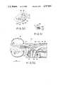
- FIG. 1is a side view showing an overall outer appearance of an ultrasonic endoscope according to the present invention
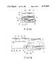
- FIG. 2is a schematic longitudinal sectional view of a hard distal end portion of the ultrasonic endoscope shown in FIG. 1;
- FIG. 3is a longitudinal sectional view of a hard distal end portion of an ultrasonic endoscope according to the first embodiment of the present invention
- FIG. 4is a bottom view of a distal end portion shown in FIG. 3;
- FIG. 5is a front view of the distal end portion shown in FIG. 3;
- FIG. 6is a cross-sectional view of the hard distal end portion of the endoscope taken along the line VI--VI in FIG. 3;
- FIG. 7is a cross-sectional view of the hard distal end portion of the endoscope taken along the line VII--VII in FIG. 3;
- FIG. 8is a cross-sectional view of the hard distal end portion of the endoscope taken along the line VIII--VIII in FIG. 3;
- FIG. 9is a cross-sectional view of the hard distal end portion of the endoscope taken along the line IX--IX in FIG. 3;
- FIG. 10is a cross-sectional view of the hard distal end portion of the endoscope taken along the line X--X in FIG. 3;
- FIG. 11is a cross-sectional view of the hard distal end portion of the endoscope taken along the line XI--XI in FIG. 3;
- FIG. 12is a cross-sectional view of the hard distal end portion of the endoscope taken along the line XII--XII in FIG. 6 and FIG. 33;
- FIG. 13is a cross-sectional view of the hard distal end portion of the endoscope taken along the line XIII--XIII in FIG. 6 and FIG. 33;
- FIG. 14is a cross-sectional view of the hard distal end portion of the endoscope taken along the line XIV--XIV in FIG. 6 and FIG. 33;
- FIG. 15is a cross-sectional view of the hard distal end portion of the endoscope taken along the line XV--XV in FIG. 5 and FIG. 33;
- FIG. 16is a longitudinal sectional view of a balloon water-supply path according to the first embodiment
- FIG. 17is a side view of an endoscope connector according to the first embodiment
- FIG. 18is a side view of an electrical connector according to the first embodiment
- FIG. 19is a plan view of the electrical connector shown in FIG. 18;
- FIG. 20is a side view showing a diagnostic range obtained when an electronic sector type ultrasonic vibrator for a longitudinal slice is used as the ultrasonic vibrator according to the first embodiment
- FIG. 21is a front view showing a diagnostic range obtained when an electronic sector type ultrasonic vibrator for a cross-sectional slice is used as the ultrasonic vibrator according to the first embodiment;
- FIGS. 22 and 23are side views showing a first modification of the hard distal end portion according to the first embodiment of the present invention.
- FIG. 24is a perspective view of a second modification of the hard distal end portion
- FIG. 25is a perspective view of a third embodiment of the hard distal end portion
- FIG. 26is a perspective view of a fourth modification of the hard distal end portion
- FIG. 27is a perspective view of a fifth modification of the hard distal end portion
- FIG. 28is a perspective view of a sixth modification of the hard distal end portion
- FIG. 29is a longitudinal sectional view showing a hard distal end portion of an ultrasonic endoscope according to a second embodiment of the present invention.
- FIG. 30is a front view showing a distal end face of an observation optical system of the distal end portion according to the second embodiment
- FIG. 31is a partial sectional view of a locking member taken along the line A--A in FIG. 30.
- FIG. 32is a longitudinal sectional view showing a modification of the hard distal end portion of the ultrasonic endoscope according to the second embodiment of the present invention.
- FIG. 33is a perspective view of the overall outer appearance of an ultrasonic endoscope according to the present invention.
- FIGS. 1 to 21show a first embodiment of an ultrasonic endoscope according to the present invention.
- ultrasonic endoscope 2includes manipulating portion 4, insertion portion 6, and sub-manipulating portion 8 provided therebetween.
- Universal cord 10is connected to portion 4.
- Connector 12 of the endoscopeis mounted on the distal end portion of cord 10.
- Electrical connector 16is connected to connector 12 through electrical cable cord 14.
- Connector 12 of cord 10is connected to a light source unit (not shown), and connector 16 of cord 14 is connected to an ultrasonic observation unit (not shown).
- hard distal end portion 22is coupled to the distal end of flexible portion 18 of portion 6 through bending portion 20.
- array type ultrasonic vibrator 26is incorporated in main body 24 of hard distal end portion 22.
- distal end face 24a of body 24is so formed as to be inclined at a proper angle ⁇ 1 (about 15°) with respect to a direction orthogonal to an axial direction.
- suction-forceps port 28is formed in face 24a of body 24, and the distal end face of observation optical system 30 and air-supply/water-supply nozzle 32 are respectively mounted thereon.
- recess 34is formed in a side surface of body 24, and ultrasonic transmitting/receiving surface 26a formed on a surface of vibrator 26 is mounted on a bottom portion of recess 34 and is exposed outwardly. Furthermore, chamfered portions 36a and 36b inclined along a direction from the bottom portion of recess 34 to an outside portion thereof are formed on a front side surface and a rear side surface, respectively. Therefore, when electronic sector type vibrator 26 for a longitudinal slice is mounted on body 24, portions 36a and 36b eliminate a problem in which a diagnostic range is narrowed by both the side surfaces of recess 34.
- Body 24includes first holder 38 for holding vibrator 26 and second holder 40 for holding system 30.
- holder 40is formed by the distal end portion of portion 24, and holder 38 is disposed behind holder 40.
- insertion hole 42having a relatively wide opening area is formed inside holder 38 to extend from the front end face to the rear end face thereof.
- Treatment tool insertion channel 44, optical fiber bundle 46 such as a light guide and an image guide of system 30, and air-supply/water-supply pipe 48are respectively provided in hole 42.
- hole 42is connected to holding portion 50 for holding vibrator 26.
- partition plate 52is disposed between vibrator 26 held by portion 50 and hole 42, as shown in FIGS. 3 and 7.
- An adhesive with a good thermal conductivitysuch as an epoxy adhesive mixed with a powder of SiC (silicon carbide) is coated on a bonding surface between vibrator 26 and portion 50 of holder 38.
- notch 54is formed in holder 38 at the front side portion of portion 50 while portion 50 is connected to holder 38, and embedded member 56 is embedded in notch 54.
- Member 56is embedded in notch 54 of holder 38 and fixed by set screws 58 (shown in FIG. 7 by broken line) to holder 38.
- bending portion 20is connected to a proximal end of distal hard portion 22.
- the bending portion 20has a number of tubular segments 21 rotatably connected to one another by connection pins 23.
- Flexible sheath 25surrounds the outer peripheral surfaces of tubular segments 21.
- the distal-end tubular segment 21is attached to a proximal end portion of first holding member 38.
- the proximal-end tubular segment 21(not shown) is connected to a distal end portion of flexible portion 18.
- Bending portion 20can be bent in a desired direction by manipulating portion 4 through a wire (not shown).
- cylindrical outer fitting portion 60 fitted on the distal end portion outer surface of holder 38 and screw insertion hole 62are formed in holder 40 for holding system 30.
- Second holder set screw 64 to be inserted in screw insertion hole 62is threadably engaged with screw hole 56a of member 56.
- Portion 60 of holder 40is fitted on the distal end portion outer surface of holder 38 so that holder 40 is detachably coupled to holder 38 by second holder set screw 64.
- sealing member 66is interposed between the inner surface of portion 60 of holder 40 and the distal end portion outer surface of holder 38, and O-ring 68 is mounted between screw 64 and holder 40. For this reason, good waterproof and air-tight properties between holders 40 and 38 are assured by sealing member 66 and O-ring 68.
- Nozzle 32 disposed on the distal end face of holder 40is coupled to air-supply/water-supply pipe 48, as shown in FIGS. 3 and 12.
- the distal end face of system 30is disposed between port 28 and nozzle 32, as shown in FIG. 5.
- injection port 32a of nozzle 32faces the distal end face of system 30, as shown in FIGS. 5 and 15. Therefore, water or air supplied through pipe 48 can be injected from port 32a of nozzle 32 toward the distal end face of system 30.
- bundle 46such as the light guide and the image guide of system 30 includes image guide portion 46a and ring-like light guide portion 46b provided on an outer surface of portion 46a, i.e., portions 46a and 46b are formed in single bundle 46.
- objective lens 70is disposed on the distal end face of system 30 so as to oppose the distal end of portion 46a of bundle 46, and the distal end portion of portion 46b of bundle 46 extends to a position of the outer surface of lens 70.
- a light beam guided through portion 46b of bundle 46is emitted from the distal end face of portion 46b so as to be inclined at proper angle ⁇ 2 (about 15°) toward a mounting surface of vibrator 26 with respect to an axis of body 24.
- Ring-like balloon mounting grooves 72a and 72bare provided at both end portions of the outer surface of body 24.
- One groove 72ais formed on the outer surface of holder 40
- other groove 72bis formed on the outer surface of holder 38, respectively.
- O-ring portionsare respectively formed at both the end portions of balloon 74 made of an elastic member such as rubber having elasticity.
- O-ring portions of balloon 74are formed and mounted in grooves 72a and 72b, respectively, and the entire outer surface of body 24 is covered with balloon 74.
- concave communication groove 76is formed on the outer surface of holder 38 so as to extend along a circumference between the mounting portion of vibrator 26 and groove 72b as shown in FIG. 16.
- balloon water-injection hole 78coupled at its one end to groove 76 and balloon suction hole (not shown) having the same arrangement as that of hole 78 are respectively formed at the proximal end of holder 38. Ends of balloon water-injection pipe 82 and balloon suction pipe (not shown) are respectively coupled to the other ends of hole 78 and the balloon suction hole. Water is supplied into groove 76 from pipe 82 and hole 78 through balloon recess water-injection hole 78a between hole 78 and groove 76, and is also supplied into balloon 74 through groove 76. When water is supplied into balloon 74, air in balloon 74 is simultaneously sucked from a balloon suction port (not shown) between groove 76 and the balloon suction hole sequentially through the balloon suction port and the balloon suction pipe.
- Portion 4 shown in FIG. 1includes bending knob 86 for bending flexible portion 20 of portion 6, eyepiece 88, air-supply/water-supply piston 90, and suction piston 92.
- Release switch 94 for remote-controlling an instrument such as a camera and release switch 96 for freezing an image of a monitor camera and the like of the ultrasonic observation unitare respectively disposed near pistons 90 and 92, and treatment tool insertion port member 98 is formed near a coupling portion of portion 8.
- each piston main body of pistons 90 and 92is incorporated in a cylinder to be movable along an axial direction.
- a water inlet port, an air inlet port, a water outlet port, and an air outlet portare formed in a cylinder of piston 90, and an air exhaust hole is formed in the piston main body of piston 90.
- the piston main body of piston 90When the piston main body of piston 90 is held at a normal position where it is projected, the water inlet and outlet ports are kept closed, the air inlet and outlet ports are kept open, and the air exhaust hole of the piston main body keeps communicating with an air passage in the cylinder of piston 90.
- the piston main body of piston 90is pushed from the normal position where it is projected, the air inlet and outlet ports are switched to be closed, and the water inlet and outlet ports are switched to be open.
- a supply port and an exhaust portare respectively formed in the cylinder 92.
- water-supply plug 100, suction plug 102, and electrical contact 104are respectively disposed on the outer surface of connector 12.
- a connecting end portion of portion 46b of bundle 46 and air-supply pipe 106are respectively provided on the distal end face of connector 12.
- Plug 100is connected to the water inlet port of piston 90 through a water-supply path formed in cord 10
- pipe 106is connected to the air inlet port of piston 90 through an air-supply path in cord 10.
- plug 102is connected to the exhaust port of piston 92 through a suction path in cord 10.
- Piston 90is selectively switched to a normal position where air supplied from an air supply source in the light source unit to portion 4 through connector 12 and cord 10 is exhausted outward through the air exhaust hole, to an exhaust position where air supplied from the air supply source in the light source unit to portion 4 through connector 12 and the air-supply path in cord 10 is supplied to pipe 48 in portion 6, and to a water-supply position where piston 90 is pushed while the air exhaust hole of piston 90 is kept closed by a finger and the like of a user, the air-supply path in cord 10 is closed, air supplied from the air supply source in the light source unit is supplied into a water-supply tank connected to plug 100 of connector 12 to pressurize an interior of the water-supply tank, and water supplied from the water-supply tank is supplied to pipe 48 in portion 6 through cord 10 and the water-supply path in portion 4.
- a suction pathcan be opened/closed by piston 92.
- Portion 8includes water-supply switching cock 108, suction switching cock 110, and lure-lock plug 112.
- a cock main body and a pivoting member pivotally incorporated in the cock main bodyare provided to each of cocks 108 and 110.
- first, second, and third coupling end portionsare formed to the cock main body of cock 108, and fourth, fifth, and sixth coupling end portions are formed in the cock main body of cock 110.
- the first coupling end portion of cock 108is coupled to the water outlet port of piston 90, and the third coupling end portion is coupled to pipe 82.
- the fourth coupling end portion of cock 110is coupled to channel 44, and the sixth coupling end portion is coupled to pipe 84.
- a first coupling hole for coupling the first coupling end portion with the second coupling end portion, and a second coupling hole for coupling the first coupling end portion with the third coupling end portion while the pivoting member is kept pivoted through a predetermined angle from an optical system washing position where the first coupling end portion is coupled to the second coupling end portion through the first coupling hole,are formed in the pivoting member of cock 108.
- a switching operationcan be selectively performed from the optical system washing position to a balloon water-supply position where the first coupling end portion is coupled to the third coupling end portion through the second coupling hole.
- the second coupling end portion of cock 108is coupled to the air outlet port of piston 90.
- a third coupling hole for coupling the fourth coupling end portion with the fifth coupling end portion, and a fourth coupling end hole for coupling the fourth coupling end portion with the sixth coupling end portion while the pivoting member is kept pivoted through a predetermined angle from an endoscope suction position where the fourth coupling end portion is coupled to the fifth coupling end portion through the third coupling holeare formed in the pivoting member of cock 110. Therefore, upon a pivoting operation of the pivoting member, a switching operation can be performed from the endoscope suction position to balloon suction position where the fourth coupling end portion is coupled to the sixth coupling end portion through the third coupling hole.
- waterproof cap 114is detachably incorporated in connector 16 coupled to connector 12 through cord 14 so as to seal contact portion 16a of connector 16 in a water-tight state.
- a matching coilis incorporated in connector 16 so as to establish electrical matching between vibrator 26 and the ultrasonic observing unit.
- a probe detecting meansfor representing characteristic items according to types of probe (endoscope 2), i.e., a difference between an insertion probe and a contact probe, a frequency of vibrator 26 incorporated in portion 22, a difference between electronic sector and electronic linear vibrators, and a difference between directions of slices in the electronic sector type (a difference between ultrasonic vibrator 26a for a longitudinal slice shown in FIG. 20 and ultrasonic vibrator 26b for a cross-sectional slice shown in FIG. 21), is incorporated in connector 16.
- the probe detecting meansis constituted by a detecting section for detecting changes in an electrical resistance and an ON/OFF state of a contact pin, an electrical circuit including a memory section (ROM), and the like.
- bundle 116 of an electrical cable (Al shield wire) of vibrator 26is coated with protective tube 118 such as a silicone tube.
- portion 6When endoscope 2 is used, portion 6 is inserted in a body cavity, portion 22 is guided to an objective portion, the pivoting member of cock 108 of portion 8 is pivoted to the balloon water-injection position, the pivoting member of cock 110 thereof is pivoted to the balloon suction position, the piston main body of piston 90 is pushed while the air exhaust hole of piston 90 of portion 4 is kept closed by a finger and the like of the user, and the piston main body of piston 92 is pushed to the suction position, thereby injecting water in balloon 74. Thereafter, the ultrasonic wave is scanned by vibrator 26 while water is kept filled in balloon 74 to obtain a tomographic image of, e.g., a body cavity wall.
- portion 60 to be fitted on the distal end portion outer surface of holder 38 for holding vibrator 26 and hole 62are respectively formed in holder 40 for holding system 30, and screw 64 is threadably engaged with hole 56a of member 56 of holder 38 while portion 60 of holder 40 is kept fitted on the distal end portion outer surface of holder 38. Therefore, by untightening screw 64, holder 40 can be detached from holder 38. For this reason, by using endoscope 2, when bundle 46 of system 30 is damaged, holder 38 for holding vibrator 26 can be separated from holder 40 for holding system 30. As a result, only damaged bundle 46 of system 30 can be replaced, so that expensive vibrator 26 which normally operates need not be replaced together with the damaged bundle of optical fibers unlike in a conventional endoscope and can be used again, thereby reducing repairing cost.
- hole 42 having a relatively wide opening areais formed in holder 38 so as to extend from the front end face to the rear end face thereof, and channel 44, bundle 46 such as the light guide and the image guide of system 30, pipe 48, and the like are provided in hole 42. For this reason, during an attaching/detaching operation of holder 40, attaching/detaching operations of channel 44, bundle 46 such as the light guide and the image guide of system 30, pipe 48, and the like can be easily performed.
- plate 52is disposed between vibrator 26 held by portion 50 of holder 38 and hole 42. For this reason, an opening area of hole 42 can be enlarged. In addition, hole 42 can be easily formed in holder 38.
- recess 34is formed on the side surface of body 24 and surface 26a of vibrator 26 is formed on the inner bottom portion of recess 34 and exposed outwardly, an outer diameter of body 24 can be reduced.
- inclined portions 36a and 36bare formed at the front and rear side surfaces of recess 34 of body 24 such that a front-to-rear interval therebetween is gradually increased outwardly from the inner bottom portion. Therefore, when electronic sector type ultrasonic vibrator 26a for a longitudinal slice is incorporated in body 24, its diagnostic range represented by symbol A in FIG. 20 is not narrowed by both the side surfaces of recess 34 of body 24. Note that a diagnostic range obtained when electronic sector type ultrasonic vibrator 26a for a cross-sectional slice is incorporated in body 24 is represented by symbol B in FIG. 21.
- the distal end face of body 24is formed inclined at proper angle ⁇ 2 with respect to a direction orthogonal to an axial direction, and a light beam guided through portion 46b of bundle 46 is radiated from the distal end surface of portion 46b so as to be inclined at proper angle ⁇ 2 toward the mounting surface side of vibrator 26 with respect to a direction orthogonal to an axial direction of body 24.
- FIG. 20shows radiation range L of portion 46b. Even when vibrator 26 is incorporated in a substantially central portion of body 24 and portion 46b of bundle 46 is mounted separate from a central portion of body 24, a visual field of portion 46a is not partially darkened, but uniform brightness of portion 46a can be obtained throughout the visual field.
- ring-like portion 46bis disposed on the outer surface of portion 46a of bundle 46 forming system 30, the entire endoscope can be made smaller than an endoscope in which portions 46a and 46b in bundle 46 are made by different bundles of optical fibers.
- an adhesive having a good thermal conductivitysuch as "an epoxy adhesive mixed with a powder of SiC (silicon carbide)" is coated on the bonding surface between vibrator 26 and portion 50 of holder 38, heat from vibrator 26 can be easily dissipated toward portion 50, thereby preventing overheating of vibrator 26.
- concave groove 76provided along the circumferential direction is formed between the mounting portion of vibrator 26 at the outer surface of holder 38 and groove 72b, and the balloon water-injection hole and the balloon suction hole are coupled to groove 76. Therefore, when air in balloon 74 is sucked, balloon 74 is sucked inside the balloon suction hole, so that the balloon suction hole does not clog.
- switch 94 for remote-controlling an instrument such as a camera, and switch 96 for freezing an image of a monitor television set and the like of the ultrasonic observing unitare provided near pistons 90 and 92 of portion 4, respectively. Therefore, the user of endoscope 2 can easily operate the instrument such as a camera during the operation of endoscope 2, and image freezing on the monitor television set and the like of the ultrasonic observing unit can be easily performed.
- the matching coil for establishing electrical matching between vibrator 26 and the ultrasonic observing unitis incorporated in connector 16. For this reason, by changes in conditions such as frequency of vibrator 26 different in accordance with types of endoscope 2 and a length from portion 22 of endoscope 2 to connector 16, the electrical matching between each type of endoscope 2 and the ultrasonic observing unit can be adjusted by the matching coil in connector 16. Therefore, a switching operation for establishing electrical matching in accordance with types of endoscope 2 need not be performed by the ultrasonic observing unit.
- the probe detecting means for representing characteristic items corresponding to types of probeis incorporated in connector 16, a type of endoscope 2 or the characteristic items corresponding to types thereof can be displayed on a screen of the monitor television set and the like of the ultrasonic observing unit and switching of electrical matching can be automatically performed while connector 16 of endoscope 2 is kept connected to the ultrasonic observing unit.
- plate 52 disposed between vibrator 26 held by portion 50 and hole 42, member 56 embedded in the notch portion formed in holder 38 at the front side portion of portion 50, and holder 38may be integrally formed.
- FIG. 24shows a second modification.
- first holder 38 for holding array type ultrasonic vibrator 26is formed in a semicircular portion of substantially pillar-like hard distal end portion 22
- second holder 40 for holding forward-view (direct-view or oblique-view) type observing optical system 30is formed in the other semicircular portion
- groove 130 and engaging pawl 132are provided to holder 40
- engaging projection 134 and engaging hole 136 for engaging with groove 130 and pawl 132are respectively provided to holder 38
- holder 38 and holder 40 for holding system 30are detachably coupled together.
- Light guide 138 and image guide 140 in system 30are formed by different bundles of optical fibers, respectively.
- Illumination lens 142 disposed to oppose the distal end face of guide 138, objective lens 144 disposed to oppose the distal end face of guide 140, and air-supply/water-supply nozzle 146are respectively disposed on the distal end face of holder 40.
- sealing member 148is mounted on a bonding portion of holder 38 with respect to holder 40, thereby maintaining air-tight and water-tight sealing between holders 38 and 40.
- FIG. 25shows a third modification.
- lens 142 disposed to oppose the distal end face of of guide 138 in system 30, and lens 144 disposed to oppose the distal end face of guide 140are disposed on the outer surface of holder 40 in the second modification, thereby forming side-view type observation optical system 30.
- groove 130is formed in holder 38
- projection 134 for engaging with groove 130is formed in holder 40
- holder 40is fixed to holder 38 by screw 64a while projection 38 of holder 40 is kept engaged with groove 130 of holder 38.
- FIG. 26shows a fourth modification.
- first holder 39having substantially the same arrangement as that of holder 38 in the second modification shown in FIG. 24 and second holder 41 having substantially the same arrangement as that of holder 40 in the second modification are respectively provided.
- Vibrator 26is incorporated in holder 39, and forward-view (direct-view or oblique-view) type observation optical system 30 is incorporated in holder 41.
- FIG. 27shows a fifth modification.
- side-view type observation optical system 30is incorporated in holder 41 in the fourth embodiment, and holder 39 is fixed to holder 41 by screw 64b while projection 134 of holder 41 is kept engaged with groove 130 of holder 39.
- FIG. 28shows a sixth modification.
- first holder 38 for holding vibrator 26is formed at the distal end portion of hard distal end portion 22, and second holder 40 for holding forward oblique-view type observation optical system 30 is formed behind holder 38.
- First and second holders 38, 40are secured to each other with screws 64c. Seal 66a provides a water tight connection therebetween.
- different types of vibrators 26can be selectively incorporated in single endoscope 2.
- electronic sector type vibrator 26may be replaced with electronic linear type vibrator 26 and vice versa, or a plurality of electronic sector type vibrators 26 having different directions of slices (a longitudinal slice or a cross-sectional slice) may be replaced with each other, thereby changing directions of slices.
- FIG. 29shows distal end constituting portion 22 of an insertion portion of an ultrasonic endoscope.
- Electronic sector scanning type ultrasonic vibrator 26is embedded in the distal end and faces hard main body 24 of portion 22.
- Balloon 74is air-tightly mounted on the distal end portion of body 24 having vibrator 26 and surrounds it.
- Groove-like port portion 76is formed in balloon 74, and water-supply tube 82 and suction tube 84 are connected to portion 76. Water is supplied to balloon 74 from tubes 82 and 84 through portion 76 to expand balloon 74. Water in balloon 74 is sucked from tube 84 through portion 76 to contract balloon 74.
- Tubes 82 and 84extend toward a manipulating portion through an insertion portion.
- Inclined portion 162is formed in a position nearer the manipulating portion from an installation position of vibrator 26 and is inclined toward ultrasonic scanning range H of vibrator 26.
- An outer wall surface of portion 162is inclined at 45° with respect to a longitudinal axis of the insertion portion.
- Opening portion 166is formed in a wall of portion 162 to detachably incorporate optical system holder 164.
- Collar 168is formed at an outer periphery edge of holder 164 and is fitted in large-diameter portion 170 formed at an outer edge of portion 166, so that holder 164 is fitted tightly in portion 166.
- An outer surface of holder 164constitutes a part of the outer wall surface of portion 162.
- O-ring 174as a sealing member fitted in groove 172 formed in an inner surface portion of portion 166 seals air-tightly and water-tightly between holder 164 and portion 166.
- Collar 168 of holder 164is tightened and fixed to the wall of portion 162 by locking members 64d each consisting of machine screw 178 with large head 176. That is, members 64 are provided at two positions, a left side and an upper portion, as shown in FIG. 30. As shown in FIG. 31, each member 64 is screwed in body 24 of portion 22, and each head 176 urges collar 168 of holder 164, thereby fixing holder 164.
- Holder 164includes lens 70, illumination lenses 182 and 183, foreceps port 28, and nozzle 32 opposing the outer surface of lens 70.
- image guide optical fiber bundle 46aoptically connected to lens 70
- two light guide optical fiber bundle 46b respectively optically connected to lenses 182 and 183are mounted and fixed to holder 164.
- Connecting pipe 44 communicating with port 28is mounted on holder 164
- tube 48 communicating with nozzle 32is connected to holder 164. That is, bundles 46a and 46b, pipe 44, and tubes 48 and 45 are mounted on holder 164, and hence can be detached together when holder 164 is removed.
- Each of these elementsextends to the manipulating portion through the insertion portion of the endoscope.
- Bundle 46ais coupled to an eyepiece of the manipulating portion.
- Bundles 46breach a connector portion through the manipulating portion and a universal cord. This is the same with tube 48 communicating with nozzle 32.
- Tube 45is connected to the foreceps port of the manipulating portion.
- electrical cable 184 extended from vibrator 26similarly extends to the manipulating portion through the insertion portion of the endoscope and is connected to the connector portion through the manipulating portion and the universal cord.
- bundles 46a and 46b in the endoscopeare damaged, member 180 is detached, and holder 164 is detached from portion 166 and pulled outside from body 24 of portion 22.
- bundles 46a and 46b and the likecan be integrally pulled out, thereby replacing the damaged components with new ones.
- Components to be replacedare not limited to bundles 46a and 46b.
- FIG. 32shows a modification of the second embodiment.
- This modificationuses an electronic linear scanning type ultrasonic vibrator and has a side-view optical observation direction.
- Other arrangementsare the same as those of the above embodiment.
- the present inventionis not limited to the above embodiments and the modifications.
- the present inventionincludes an endoscope having an ultrasonic vibrator scanning direction toward the distal end, an endoscope without a groove in which a balloon is incorporated, and the like.
- scanning systemis not limited to an electronic one but may be a mechanical one, i.e., may be variously modified and carried out without departing from the spirit and scope of the present invention.
Landscapes
- Health & Medical Sciences (AREA)
- Life Sciences & Earth Sciences (AREA)
- Surgery (AREA)
- Physics & Mathematics (AREA)
- Biomedical Technology (AREA)
- Heart & Thoracic Surgery (AREA)
- Pathology (AREA)
- Radiology & Medical Imaging (AREA)
- Biophysics (AREA)
- Engineering & Computer Science (AREA)
- Veterinary Medicine (AREA)
- Nuclear Medicine, Radiotherapy & Molecular Imaging (AREA)
- Medical Informatics (AREA)
- Molecular Biology (AREA)
- Animal Behavior & Ethology (AREA)
- General Health & Medical Sciences (AREA)
- Public Health (AREA)
- Optics & Photonics (AREA)
- Gynecology & Obstetrics (AREA)
- Ultra Sonic Daignosis Equipment (AREA)
Abstract
Description
Claims (10)
Applications Claiming Priority (4)
| Application Number | Priority Date | Filing Date | Title |
|---|---|---|---|
| JP61-116667 | 1986-05-21 | ||
| JP61116667AJPH074371B2 (en) | 1986-05-21 | 1986-05-21 | Ultrasound endoscope |
| JP61-259758 | 1986-10-31 | ||
| JP25975886AJPH074375B2 (en) | 1986-10-31 | 1986-10-31 | Ultrasound endoscope |
Publications (1)
| Publication Number | Publication Date |
|---|---|
| US4757819Atrue US4757819A (en) | 1988-07-19 |
Family
ID=26454961
Family Applications (1)
| Application Number | Title | Priority Date | Filing Date |
|---|---|---|---|
| US07/050,710Expired - LifetimeUS4757819A (en) | 1986-05-21 | 1987-05-14 | Ultrasonic endoscope |
Country Status (2)
| Country | Link |
|---|---|
| US (1) | US4757819A (en) |
| DE (1) | DE3716964A1 (en) |
Cited By (47)
| Publication number | Priority date | Publication date | Assignee | Title |
|---|---|---|---|---|
| US4982724A (en)* | 1987-12-28 | 1991-01-08 | Olympus Opicals Co. | Endoscope apparatus |
| US5131396A (en)* | 1990-06-25 | 1992-07-21 | Fuji Photo Optical Co., Ltd. | Ultrasonic internal examination system |
| US5411020A (en)* | 1990-11-27 | 1995-05-02 | Asahi Kogaku Kogyo Kabushiki Kaisha | Structure of the distal end portion of an endoscope |
| WO2000035349A1 (en)* | 1998-12-16 | 2000-06-22 | Fox Hollow Technologies, Inc. | Guidewire having sidewise looking imaging capabilities and method |
| US6178968B1 (en) | 1995-06-07 | 2001-01-30 | Edwards Lifesciences Corp. | Method of endoscopically visualized occlusion of the side branches of an anatomical passageway |
| US6238336B1 (en)* | 1998-03-04 | 2001-05-29 | Asahi Kogaku Kogyo Kabushiki Kaisha | Ultrasonic endoscope including radial scanning and linear scanning ultrasonic transducers |
| US6328730B1 (en)* | 1999-03-26 | 2001-12-11 | William W. Harkrider, Jr. | Endoluminal multi-luminal surgical sheath and method |
| US6461304B1 (en)* | 1999-03-30 | 2002-10-08 | Fuji Photo Optical Co., Ltd. | Ultrasound inspection apparatus detachably connected to endoscope |
| USD474745S1 (en) | 2001-12-31 | 2003-05-20 | Karl Storz Imaging, Inc. | Cable boot and connector |
| US20040082883A1 (en)* | 2002-10-18 | 2004-04-29 | Fuji Photo Optical Co., Ltd. | Ultrasound endoscope |
| US20050228289A1 (en)* | 2004-03-31 | 2005-10-13 | Fujinon Corporation | Ultrasonic endoscope |
| US20050273012A1 (en)* | 2001-06-29 | 2005-12-08 | Aviv Jonathan E | Optical transesophageal echocardiography probe |
| US20060025691A1 (en)* | 2004-07-29 | 2006-02-02 | Fujinon Corporation | Ultrasonic endoscope |
| US20060270907A1 (en)* | 2005-05-27 | 2006-11-30 | Eckart Klemm | Endoscope, in particular for tracheotomy |
| USD533663S1 (en)* | 2004-07-15 | 2006-12-12 | Olympus Corporation | Treatment apparatus for endoscope |
| USD533662S1 (en)* | 2004-07-15 | 2006-12-12 | Olympus Corporation | Treatment apparatus for endoscope |
| USD534653S1 (en)* | 2004-07-15 | 2007-01-02 | Olympus Corporation | Treatment apparatus for endoscope |
| US20070010840A1 (en)* | 2003-04-22 | 2007-01-11 | Fox Hollow Technologies, Inc. | Methods and devices for cutting tissue at a vascular location |
| USD536093S1 (en)* | 2004-07-15 | 2007-01-30 | Olympus Corporation | Treatment apparatus for endoscope |
| US20070276419A1 (en)* | 2006-05-26 | 2007-11-29 | Fox Hollow Technologies, Inc. | Methods and devices for rotating an active element and an energy emitter on a catheter |
| US20080065125A1 (en)* | 2000-12-20 | 2008-03-13 | Foxhollow Technologies, Inc. | High capacity debulking catheter with distal driven cutting wheel |
| US20080086032A1 (en)* | 2006-10-04 | 2008-04-10 | Hironobu Ichimura | Endoscope |
| US20090299394A1 (en)* | 1999-08-19 | 2009-12-03 | Fox Hollow Technologies, Inc. | Methods and devices for cutting tissue |
| US20100130996A1 (en)* | 2008-10-13 | 2010-05-27 | Fox Hollow Technologies, Inc. | Devices and methods for manipulating a catheter shaft |
| US20100198240A1 (en)* | 2000-12-20 | 2010-08-05 | Fox Hollow Technologies, Inc. | Debulking catheters and methods |
| US20100249503A1 (en)* | 2009-03-05 | 2010-09-30 | Olympus Medical Systems Corp. | Medical instrument |
| US20100256535A1 (en)* | 2009-04-03 | 2010-10-07 | Pavel Novak | Method for preparing an apparatus for treating a human or animal body by mechanical shockwaves |
| US20100256536A1 (en)* | 2009-04-03 | 2010-10-07 | Pavel Novak | Apparatus for treating a human or animal body by mechanical shockwaves having an exchangeable impact body |
| US20100292721A1 (en)* | 2009-05-14 | 2010-11-18 | Fox Hollow Technologies, Inc. | Easily cleaned atherectomy catheters and methods of use |
| US20100298850A1 (en)* | 1999-08-19 | 2010-11-25 | Fox Hollow Technologies, Inc. | Atherectomy catheter with aligned imager |
| US20110130777A1 (en)* | 2009-12-02 | 2011-06-02 | Fox Hollow Technologies, Inc. | Methods and devices for cutting tissue |
| US20110144673A1 (en)* | 2009-12-11 | 2011-06-16 | Fox Hollow Technologies, Inc. | Material removal device having improved material capture efficiency and methods of use |
| US20120000272A1 (en)* | 2009-02-10 | 2012-01-05 | Francisco Santiago Soriano Romero | Device for Controlling Leaks From an Endoscope |
| US8328829B2 (en) | 1999-08-19 | 2012-12-11 | Covidien Lp | High capacity debulking catheter with razor edge cutting window |
| US8784440B2 (en) | 2008-02-25 | 2014-07-22 | Covidien Lp | Methods and devices for cutting tissue |
| US8808186B2 (en) | 2010-11-11 | 2014-08-19 | Covidien Lp | Flexible debulking catheters with imaging and methods of use and manufacture |
| US8920450B2 (en) | 2010-10-28 | 2014-12-30 | Covidien Lp | Material removal device and method of use |
| US20150018617A1 (en)* | 2013-02-06 | 2015-01-15 | Olympus Medical Systems Corp. | Stereoscopic endoscope |
| US8992717B2 (en) | 2011-09-01 | 2015-03-31 | Covidien Lp | Catheter with helical drive shaft and methods of manufacture |
| US9119662B2 (en) | 2010-06-14 | 2015-09-01 | Covidien Lp | Material removal device and method of use |
| US9532844B2 (en) | 2012-09-13 | 2017-01-03 | Covidien Lp | Cleaning device for medical instrument and method of use |
| US9687266B2 (en) | 2009-04-29 | 2017-06-27 | Covidien Lp | Methods and devices for cutting and abrading tissue |
| US9943329B2 (en) | 2012-11-08 | 2018-04-17 | Covidien Lp | Tissue-removing catheter with rotatable cutter |
| US10213224B2 (en) | 2014-06-27 | 2019-02-26 | Covidien Lp | Cleaning device for catheter and catheter including the same |
| US10292721B2 (en) | 2015-07-20 | 2019-05-21 | Covidien Lp | Tissue-removing catheter including movable distal tip |
| US10314664B2 (en) | 2015-10-07 | 2019-06-11 | Covidien Lp | Tissue-removing catheter and tissue-removing element with depth stop |
| US10314667B2 (en) | 2015-03-25 | 2019-06-11 | Covidien Lp | Cleaning device for cleaning medical instrument |
Families Citing this family (10)
| Publication number | Priority date | Publication date | Assignee | Title |
|---|---|---|---|---|
| US5020539A (en)* | 1988-03-30 | 1991-06-04 | Olympus Optical Co., Ltd. | Ultrasonic endoscope apparatus |
| JPH01291844A (en)* | 1988-05-18 | 1989-11-24 | Olympus Optical Co Ltd | Ultrasonic probe |
| US5817015A (en)* | 1993-06-22 | 1998-10-06 | Adair; Edwin L. | Endoscope with reusable core and disposable sheath with passageways |
| JP3619424B2 (en)* | 2000-05-10 | 2005-02-09 | ペンタックス株式会社 | Radial scanning forward-view ultrasound endoscope |
| US6471654B2 (en)* | 2000-05-10 | 2002-10-29 | Asahi Kogaku Kogyo Kabushiki Kaisha | Ultrasonic endoscope |
| US6511431B2 (en)* | 2000-05-10 | 2003-01-28 | Pentax Corporation | Radial scan, forward viewing ultrasonic endoscope |
| JP3579651B2 (en)* | 2000-11-21 | 2004-10-20 | ペンタックス株式会社 | Ultrasound endoscope |
| JP3579646B2 (en)* | 2000-11-21 | 2004-10-20 | ペンタックス株式会社 | Ultrasound endoscope |
| US6468221B2 (en)* | 2000-11-21 | 2002-10-22 | Asahi Kogaku Kogyo Kabushiki Kaisha | Ultrasonic endoscope |
| JP6448055B2 (en)* | 2015-11-09 | 2019-01-09 | 富士フイルム株式会社 | Ultrasound endoscope and method for manufacturing ultrasound endoscope |
Citations (4)
| Publication number | Priority date | Publication date | Assignee | Title |
|---|---|---|---|---|
| US4375818A (en)* | 1979-03-12 | 1983-03-08 | Olympus Optical Company Ltd. | Ultrasonic diagnosis system assembled into endoscope |
| US4391282A (en)* | 1979-10-24 | 1983-07-05 | Olympus Optical Company Limited | Coeliac cavity ultrasonic diagnosis apparatus |
| US4489728A (en)* | 1981-03-22 | 1984-12-25 | Olympus Optical Co., Ltd. | Device for diagnosing body cavity interior with supersonic waves |
| US4494549A (en)* | 1981-05-21 | 1985-01-22 | Olympus Optical Co., Ltd. | Device for diagnosing body cavity interiors with supersonic waves |
Family Cites Families (6)
| Publication number | Priority date | Publication date | Assignee | Title |
|---|---|---|---|---|
| DE3111196A1 (en)* | 1980-03-31 | 1982-02-04 | Governing Council University of Toronto, Toronto, Ontario | DEVICE FOR THE EXAMINATION OF THE GASTAL ARM CANAL |
| US4489727A (en)* | 1981-03-22 | 1984-12-25 | Olympus Optical Co., Ltd. | Device for diagnosing body cavity interior with supersonic waves |
| DE3121512A1 (en)* | 1981-05-29 | 1982-12-23 | SRI International, 94025 Menlo Park, Calif. | Endoscopic probe, device and associated method |
| JPS58139107U (en)* | 1982-03-15 | 1983-09-19 | オリンパス光学工業株式会社 | Intrabody ultrasound diagnostic device |
| US4462408A (en)* | 1982-05-17 | 1984-07-31 | Advanced Technology Laboratories, Inc. | Ultrasonic endoscope having elongated array mounted in manner allowing it to remain flexible |
| FR2552652B3 (en)* | 1983-09-29 | 1985-12-13 | Fornage Bruno | IMPROVEMENT IN ENDOCAVITY MEDICAL ECHOGRAPHY PROBES |
- 1987
- 1987-05-14USUS07/050,710patent/US4757819A/ennot_activeExpired - Lifetime
- 1987-05-20DEDE19873716964patent/DE3716964A1/enactiveGranted
Patent Citations (4)
| Publication number | Priority date | Publication date | Assignee | Title |
|---|---|---|---|---|
| US4375818A (en)* | 1979-03-12 | 1983-03-08 | Olympus Optical Company Ltd. | Ultrasonic diagnosis system assembled into endoscope |
| US4391282A (en)* | 1979-10-24 | 1983-07-05 | Olympus Optical Company Limited | Coeliac cavity ultrasonic diagnosis apparatus |
| US4489728A (en)* | 1981-03-22 | 1984-12-25 | Olympus Optical Co., Ltd. | Device for diagnosing body cavity interior with supersonic waves |
| US4494549A (en)* | 1981-05-21 | 1985-01-22 | Olympus Optical Co., Ltd. | Device for diagnosing body cavity interiors with supersonic waves |
Cited By (97)
| Publication number | Priority date | Publication date | Assignee | Title |
|---|---|---|---|---|
| US4982724A (en)* | 1987-12-28 | 1991-01-08 | Olympus Opicals Co. | Endoscope apparatus |
| US5131396A (en)* | 1990-06-25 | 1992-07-21 | Fuji Photo Optical Co., Ltd. | Ultrasonic internal examination system |
| US5411020A (en)* | 1990-11-27 | 1995-05-02 | Asahi Kogaku Kogyo Kabushiki Kaisha | Structure of the distal end portion of an endoscope |
| US6178968B1 (en) | 1995-06-07 | 2001-01-30 | Edwards Lifesciences Corp. | Method of endoscopically visualized occlusion of the side branches of an anatomical passageway |
| US6238336B1 (en)* | 1998-03-04 | 2001-05-29 | Asahi Kogaku Kogyo Kabushiki Kaisha | Ultrasonic endoscope including radial scanning and linear scanning ultrasonic transducers |
| WO2000035349A1 (en)* | 1998-12-16 | 2000-06-22 | Fox Hollow Technologies, Inc. | Guidewire having sidewise looking imaging capabilities and method |
| US6328730B1 (en)* | 1999-03-26 | 2001-12-11 | William W. Harkrider, Jr. | Endoluminal multi-luminal surgical sheath and method |
| US6461304B1 (en)* | 1999-03-30 | 2002-10-08 | Fuji Photo Optical Co., Ltd. | Ultrasound inspection apparatus detachably connected to endoscope |
| US9788854B2 (en) | 1999-08-19 | 2017-10-17 | Covidien Lp | Debulking catheters and methods |
| US10022145B2 (en) | 1999-08-19 | 2018-07-17 | Covidien Lp | Methods and devices for cutting tissue |
| US9615850B2 (en) | 1999-08-19 | 2017-04-11 | Covidien Lp | Atherectomy catheter with aligned imager |
| US8911459B2 (en) | 1999-08-19 | 2014-12-16 | Covidien Lp | Debulking catheters and methods |
| US9532799B2 (en) | 1999-08-19 | 2017-01-03 | Covidien Lp | Method and devices for cutting tissue |
| US8328829B2 (en) | 1999-08-19 | 2012-12-11 | Covidien Lp | High capacity debulking catheter with razor edge cutting window |
| US8597315B2 (en) | 1999-08-19 | 2013-12-03 | Covidien Lp | Atherectomy catheter with first and second imaging devices |
| US20090299394A1 (en)* | 1999-08-19 | 2009-12-03 | Fox Hollow Technologies, Inc. | Methods and devices for cutting tissue |
| US8998937B2 (en) | 1999-08-19 | 2015-04-07 | Covidien Lp | Methods and devices for cutting tissue |
| US9486237B2 (en) | 1999-08-19 | 2016-11-08 | Covidien Lp | Methods and devices for cutting tissue |
| US20100298850A1 (en)* | 1999-08-19 | 2010-11-25 | Fox Hollow Technologies, Inc. | Atherectomy catheter with aligned imager |
| US8226674B2 (en) | 2000-12-20 | 2012-07-24 | Tyco Healthcare Group Lp | Debulking catheters and methods |
| US20080065125A1 (en)* | 2000-12-20 | 2008-03-13 | Foxhollow Technologies, Inc. | High capacity debulking catheter with distal driven cutting wheel |
| US9241733B2 (en) | 2000-12-20 | 2016-01-26 | Covidien Lp | Debulking catheter |
| US8469979B2 (en) | 2000-12-20 | 2013-06-25 | Covidien Lp | High capacity debulking catheter with distal driven cutting wheel |
| US8052704B2 (en) | 2000-12-20 | 2011-11-08 | Foxhollow Technologies, Inc. | High capacity debulking catheter with distal driven cutting wheel |
| US20100198240A1 (en)* | 2000-12-20 | 2010-08-05 | Fox Hollow Technologies, Inc. | Debulking catheters and methods |
| US20050273012A1 (en)* | 2001-06-29 | 2005-12-08 | Aviv Jonathan E | Optical transesophageal echocardiography probe |
| USD474745S1 (en) | 2001-12-31 | 2003-05-20 | Karl Storz Imaging, Inc. | Cable boot and connector |
| USD482334S1 (en) | 2001-12-31 | 2003-11-18 | Karl Storz Imaging Inc. | Cable boot and connector |
| US20040082883A1 (en)* | 2002-10-18 | 2004-04-29 | Fuji Photo Optical Co., Ltd. | Ultrasound endoscope |
| US7318806B2 (en)* | 2002-10-18 | 2008-01-15 | Fujinon Corporation | Ultrasound endoscope |
| US8246640B2 (en) | 2003-04-22 | 2012-08-21 | Tyco Healthcare Group Lp | Methods and devices for cutting tissue at a vascular location |
| US8961546B2 (en) | 2003-04-22 | 2015-02-24 | Covidien Lp | Methods and devices for cutting tissue at a vascular location |
| US9999438B2 (en) | 2003-04-22 | 2018-06-19 | Covidien Lp | Methods and devices for cutting tissue at a vascular location |
| US20070010840A1 (en)* | 2003-04-22 | 2007-01-11 | Fox Hollow Technologies, Inc. | Methods and devices for cutting tissue at a vascular location |
| US20050228289A1 (en)* | 2004-03-31 | 2005-10-13 | Fujinon Corporation | Ultrasonic endoscope |
| US7946993B2 (en)* | 2004-03-31 | 2011-05-24 | Fujinon Corporation | Ultrasonic endoscope |
| USD536093S1 (en)* | 2004-07-15 | 2007-01-30 | Olympus Corporation | Treatment apparatus for endoscope |
| USD533663S1 (en)* | 2004-07-15 | 2006-12-12 | Olympus Corporation | Treatment apparatus for endoscope |
| USD533662S1 (en)* | 2004-07-15 | 2006-12-12 | Olympus Corporation | Treatment apparatus for endoscope |
| USD534653S1 (en)* | 2004-07-15 | 2007-01-02 | Olympus Corporation | Treatment apparatus for endoscope |
| US20060025691A1 (en)* | 2004-07-29 | 2006-02-02 | Fujinon Corporation | Ultrasonic endoscope |
| US7488288B2 (en)* | 2004-07-29 | 2009-02-10 | Fujinon Corporation | Ultrasonic endoscope |
| US20060270907A1 (en)* | 2005-05-27 | 2006-11-30 | Eckart Klemm | Endoscope, in particular for tracheotomy |
| US7658711B2 (en)* | 2005-05-27 | 2010-02-09 | Karl Storz Gmbh & Co. Kg | Endoscope, in particular for tracheotomy |
| US11666355B2 (en) | 2006-05-26 | 2023-06-06 | Covidien Lp | Catheter including cutting element and energy emitting element |
| US20070276419A1 (en)* | 2006-05-26 | 2007-11-29 | Fox Hollow Technologies, Inc. | Methods and devices for rotating an active element and an energy emitter on a catheter |
| US10588653B2 (en) | 2006-05-26 | 2020-03-17 | Covidien Lp | Catheter including cutting element and energy emitting element |
| US9801647B2 (en) | 2006-05-26 | 2017-10-31 | Covidien Lp | Catheter including cutting element and energy emitting element |
| US20080086032A1 (en)* | 2006-10-04 | 2008-04-10 | Hironobu Ichimura | Endoscope |
| JP2008086664A (en)* | 2006-10-04 | 2008-04-17 | Olympus Medical Systems Corp | Endoscope |
| US8784440B2 (en) | 2008-02-25 | 2014-07-22 | Covidien Lp | Methods and devices for cutting tissue |
| US10219824B2 (en) | 2008-02-25 | 2019-03-05 | Covidien Lp | Methods and devices for cutting tissue |
| US9445834B2 (en) | 2008-02-25 | 2016-09-20 | Covidien Lp | Methods and devices for cutting tissue |
| US9192406B2 (en) | 2008-10-13 | 2015-11-24 | Covidien Lp | Method for manipulating catheter shaft |
| US10507037B2 (en) | 2008-10-13 | 2019-12-17 | Covidien Lp | Method for manipulating catheter shaft |
| US20100130996A1 (en)* | 2008-10-13 | 2010-05-27 | Fox Hollow Technologies, Inc. | Devices and methods for manipulating a catheter shaft |
| US8414604B2 (en) | 2008-10-13 | 2013-04-09 | Covidien Lp | Devices and methods for manipulating a catheter shaft |
| US20120000272A1 (en)* | 2009-02-10 | 2012-01-05 | Francisco Santiago Soriano Romero | Device for Controlling Leaks From an Endoscope |
| US20100249503A1 (en)* | 2009-03-05 | 2010-09-30 | Olympus Medical Systems Corp. | Medical instrument |
| US20100256535A1 (en)* | 2009-04-03 | 2010-10-07 | Pavel Novak | Method for preparing an apparatus for treating a human or animal body by mechanical shockwaves |
| US20100256536A1 (en)* | 2009-04-03 | 2010-10-07 | Pavel Novak | Apparatus for treating a human or animal body by mechanical shockwaves having an exchangeable impact body |
| US10555753B2 (en) | 2009-04-29 | 2020-02-11 | Covidien Lp | Methods and devices for cutting and abrading tissue |
| US9687266B2 (en) | 2009-04-29 | 2017-06-27 | Covidien Lp | Methods and devices for cutting and abrading tissue |
| US8192452B2 (en) | 2009-05-14 | 2012-06-05 | Tyco Healthcare Group Lp | Easily cleaned atherectomy catheters and methods of use |
| US9220530B2 (en) | 2009-05-14 | 2015-12-29 | Covidien Lp | Easily cleaned atherectomy catheters and methods of use |
| US8574249B2 (en) | 2009-05-14 | 2013-11-05 | Covidien Lp | Easily cleaned atherectomy catheters and methods of use |
| US20100292721A1 (en)* | 2009-05-14 | 2010-11-18 | Fox Hollow Technologies, Inc. | Easily cleaned atherectomy catheters and methods of use |
| US20110130777A1 (en)* | 2009-12-02 | 2011-06-02 | Fox Hollow Technologies, Inc. | Methods and devices for cutting tissue |
| US8496677B2 (en) | 2009-12-02 | 2013-07-30 | Covidien Lp | Methods and devices for cutting tissue |
| US10499947B2 (en) | 2009-12-02 | 2019-12-10 | Covidien Lp | Device for cutting tissue |
| US9687267B2 (en) | 2009-12-02 | 2017-06-27 | Covidien Lp | Device for cutting tissue |
| US9913659B2 (en) | 2009-12-11 | 2018-03-13 | Covidien Lp | Material removal device having improved material capture efficiency and methods of use |
| US10751082B2 (en) | 2009-12-11 | 2020-08-25 | Covidien Lp | Material removal device having improved material capture efficiency and methods of use |
| US20110144673A1 (en)* | 2009-12-11 | 2011-06-16 | Fox Hollow Technologies, Inc. | Material removal device having improved material capture efficiency and methods of use |
| US9028512B2 (en) | 2009-12-11 | 2015-05-12 | Covidien Lp | Material removal device having improved material capture efficiency and methods of use |
| US9855072B2 (en) | 2010-06-14 | 2018-01-02 | Covidien Lp | Material removal device and method of use |
| US9119662B2 (en) | 2010-06-14 | 2015-09-01 | Covidien Lp | Material removal device and method of use |
| US8920450B2 (en) | 2010-10-28 | 2014-12-30 | Covidien Lp | Material removal device and method of use |
| US9717520B2 (en) | 2010-10-28 | 2017-08-01 | Covidien Lp | Material removal device and method of use |
| US10952762B2 (en) | 2010-10-28 | 2021-03-23 | Covidien Lp | Material removal device and method of use |
| US9326789B2 (en) | 2010-11-11 | 2016-05-03 | Covidien Lp | Flexible debulking catheters with imaging and methods of use and manufacture |
| US8808186B2 (en) | 2010-11-11 | 2014-08-19 | Covidien Lp | Flexible debulking catheters with imaging and methods of use and manufacture |
| US9770259B2 (en) | 2011-09-01 | 2017-09-26 | Covidien Lp | Catheter with helical drive shaft and methods of manufacture |
| US10335188B2 (en) | 2011-09-01 | 2019-07-02 | Covidien Lp | Methods of manufacture of catheter with helical drive shaft |
| US8992717B2 (en) | 2011-09-01 | 2015-03-31 | Covidien Lp | Catheter with helical drive shaft and methods of manufacture |
| US9579157B2 (en) | 2012-09-13 | 2017-02-28 | Covidien Lp | Cleaning device for medical instrument and method of use |
| US10406316B2 (en) | 2012-09-13 | 2019-09-10 | Covidien Lp | Cleaning device for medical instrument and method of use |
| US10434281B2 (en) | 2012-09-13 | 2019-10-08 | Covidien Lp | Cleaning device for medical instrument and method of use |
| US9532844B2 (en) | 2012-09-13 | 2017-01-03 | Covidien Lp | Cleaning device for medical instrument and method of use |
| US10932811B2 (en) | 2012-11-08 | 2021-03-02 | Covidien Lp | Tissue-removing catheter with rotatable cutter |
| US9943329B2 (en) | 2012-11-08 | 2018-04-17 | Covidien Lp | Tissue-removing catheter with rotatable cutter |
| US20150018617A1 (en)* | 2013-02-06 | 2015-01-15 | Olympus Medical Systems Corp. | Stereoscopic endoscope |
| US10213224B2 (en) | 2014-06-27 | 2019-02-26 | Covidien Lp | Cleaning device for catheter and catheter including the same |
| US12048453B2 (en) | 2014-06-27 | 2024-07-30 | Covidien Lp | Cleaning device for catheter and catheter including the same |
| US10314667B2 (en) | 2015-03-25 | 2019-06-11 | Covidien Lp | Cleaning device for cleaning medical instrument |
| US10292721B2 (en) | 2015-07-20 | 2019-05-21 | Covidien Lp | Tissue-removing catheter including movable distal tip |
| US10314664B2 (en) | 2015-10-07 | 2019-06-11 | Covidien Lp | Tissue-removing catheter and tissue-removing element with depth stop |
Also Published As
| Publication number | Publication date |
|---|---|
| DE3716964C2 (en) | 1992-11-19 |
| DE3716964A1 (en) | 1987-11-26 |
Similar Documents
| Publication | Publication Date | Title |
|---|---|---|
| US4757819A (en) | Ultrasonic endoscope | |
| US4779624A (en) | Ultrasonic endoscope | |
| EP1870014B1 (en) | Endoscope insertion portion | |
| CN101357060B (en) | Endoscope | |
| US4756304A (en) | Arthroscopic video camera system | |
| US5020539A (en) | Ultrasonic endoscope apparatus | |
| US8801603B2 (en) | Endoscope | |
| US4989586A (en) | Endoscope having a solid-state image pickup device | |
| US20050027165A1 (en) | Removable operating device for a flexible endoscopic probe for medical purposes | |
| US4669449A (en) | Submergible laryngoscope metallic housing for fiber optics power source | |
| US20090253966A1 (en) | Distal end portion of endoscope | |
| US5411020A (en) | Structure of the distal end portion of an endoscope | |
| JP2000056238A (en) | Endoscopic apparatus | |
| CN108685555B (en) | Endoscope and method for mounting optical system in endoscope | |
| US5431150A (en) | Covered endoscope having a cap cover for shielding a dilation tube cap with which a dilation tube is coupled | |
| JP2001000388A (en) | Endoscope | |
| JP3681781B2 (en) | Electronic endoscope | |
| JP4129312B2 (en) | Endoscope device | |
| JPH074371B2 (en) | Ultrasound endoscope | |
| JP3346631B2 (en) | Waterproof cap for endoscope | |
| JP3017754B2 (en) | Endoscope | |
| JPH0345682Y2 (en) | ||
| JP3260914B2 (en) | Rigid endoscope | |
| JPH0554342B2 (en) | ||
| CN107569203B (en) | A kind of endoscope |
Legal Events
| Date | Code | Title | Description |
|---|---|---|---|
| AS | Assignment | Owner name:OLYMPUS OPTICAL CO., LTD., 43-2, 2-CHOME, HATAGAYA Free format text:ASSIGNMENT OF ASSIGNORS INTEREST.;ASSIGNORS:YOKOI, TAKESHI;KAWASHIMA, MASAHIRO;MATSUI, KOICHI;AND OTHERS;REEL/FRAME:004713/0677 Effective date:19870506 Owner name:OLYMPUS OPTICAL CO., LTD., A CORP. OF JAPAN,JAPAN Free format text:ASSIGNMENT OF ASSIGNORS INTEREST;ASSIGNORS:YOKOI, TAKESHI;KAWASHIMA, MASAHIRO;MATSUI, KOICHI;AND OTHERS;REEL/FRAME:004713/0677 Effective date:19870506 | |
| STCF | Information on status: patent grant | Free format text:PATENTED CASE | |
| FEPP | Fee payment procedure | Free format text:PAYOR NUMBER ASSIGNED (ORIGINAL EVENT CODE: ASPN); ENTITY STATUS OF PATENT OWNER: LARGE ENTITY | |
| FPAY | Fee payment | Year of fee payment:4 | |
| FEPP | Fee payment procedure | Free format text:PAYOR NUMBER ASSIGNED (ORIGINAL EVENT CODE: ASPN); ENTITY STATUS OF PATENT OWNER: LARGE ENTITY Free format text:PAYER NUMBER DE-ASSIGNED (ORIGINAL EVENT CODE: RMPN); ENTITY STATUS OF PATENT OWNER: LARGE ENTITY | |
| FPAY | Fee payment | Year of fee payment:8 | |
| FPAY | Fee payment | Year of fee payment:12 |