US4756302A - Blood pumping system and method - Google Patents
Blood pumping system and methodDownload PDFInfo
- Publication number
- US4756302A US4756302AUS06/933,490US93349086AUS4756302AUS 4756302 AUS4756302 AUS 4756302AUS 93349086 AUS93349086 AUS 93349086AUS 4756302 AUS4756302 AUS 4756302A
- Authority
- US
- United States
- Prior art keywords
- pump
- ventricle
- systole
- cycle
- fill
- Prior art date
- Legal status (The legal status is an assumption and is not a legal conclusion. Google has not performed a legal analysis and makes no representation as to the accuracy of the status listed.)
- Expired - Lifetime
Links
- 238000000034methodMethods0.000titleclaimsabstractdescription20
- 239000008280bloodSubstances0.000titledescription11
- 210000004369bloodAnatomy0.000titledescription11
- 238000005086pumpingMethods0.000titledescription5
- 230000000977initiatory effectEffects0.000claimsabstractdescription15
- 230000002861ventricularEffects0.000claimsdescription42
- 238000000718qrs complexMethods0.000claimsdescription4
- 210000005240left ventricleAnatomy0.000description16
- 230000036316preloadEffects0.000description13
- 230000008602contractionEffects0.000description5
- 230000013011matingEffects0.000description4
- 230000003111delayed effectEffects0.000description3
- 238000010586diagramMethods0.000description3
- 239000000463materialSubstances0.000description3
- 238000012544monitoring processMethods0.000description3
- 210000004165myocardiumAnatomy0.000description3
- 206010003694AtrophyDiseases0.000description2
- 229920004934Dacron®Polymers0.000description2
- 210000000709aortaAnatomy0.000description2
- 210000001765aortic valveAnatomy0.000description2
- 230000037444atrophyEffects0.000description2
- 238000005452bendingMethods0.000description2
- 230000000747cardiac effectEffects0.000description2
- 230000000694effectsEffects0.000description2
- 238000012986modificationMethods0.000description2
- 230000004048modificationEffects0.000description2
- 239000005020polyethylene terephthalateSubstances0.000description2
- 230000001105regulatory effectEffects0.000description2
- 230000001960triggered effectEffects0.000description2
- 210000000683abdominal cavityAnatomy0.000description1
- 210000001367arteryAnatomy0.000description1
- 230000000712assemblyEffects0.000description1
- 238000000429assemblyMethods0.000description1
- 230000004087circulationEffects0.000description1
- 230000007423decreaseEffects0.000description1
- 238000001514detection methodMethods0.000description1
- 238000007599dischargingMethods0.000description1
- 239000012530fluidSubstances0.000description1
- 230000001771impaired effectEffects0.000description1
- 238000002513implantationMethods0.000description1
- 230000006698inductionEffects0.000description1
- 230000007257malfunctionEffects0.000description1
- 230000035479physiological effects, processes and functionsEffects0.000description1
- 238000011084recoveryMethods0.000description1
- 230000011664signalingEffects0.000description1
- 230000001360synchronised effectEffects0.000description1
- 230000001839systemic circulationEffects0.000description1
- 230000009885systemic effectEffects0.000description1
Images


Classifications
- A—HUMAN NECESSITIES
- A61—MEDICAL OR VETERINARY SCIENCE; HYGIENE
- A61M—DEVICES FOR INTRODUCING MEDIA INTO, OR ONTO, THE BODY; DEVICES FOR TRANSDUCING BODY MEDIA OR FOR TAKING MEDIA FROM THE BODY; DEVICES FOR PRODUCING OR ENDING SLEEP OR STUPOR
- A61M60/00—Blood pumps; Devices for mechanical circulatory actuation; Balloon pumps for circulatory assistance
- A61M60/50—Details relating to control
- A61M60/585—User interfaces
- A—HUMAN NECESSITIES
- A61—MEDICAL OR VETERINARY SCIENCE; HYGIENE
- A61M—DEVICES FOR INTRODUCING MEDIA INTO, OR ONTO, THE BODY; DEVICES FOR TRANSDUCING BODY MEDIA OR FOR TAKING MEDIA FROM THE BODY; DEVICES FOR PRODUCING OR ENDING SLEEP OR STUPOR
- A61M60/00—Blood pumps; Devices for mechanical circulatory actuation; Balloon pumps for circulatory assistance
- A61M60/10—Location thereof with respect to the patient's body
- A61M60/122—Implantable pumps or pumping devices, i.e. the blood being pumped inside the patient's body
- A61M60/165—Implantable pumps or pumping devices, i.e. the blood being pumped inside the patient's body implantable in, on, or around the heart
- A61M60/178—Implantable pumps or pumping devices, i.e. the blood being pumped inside the patient's body implantable in, on, or around the heart drawing blood from a ventricle and returning the blood to the arterial system via a cannula external to the ventricle, e.g. left or right ventricular assist devices
- A—HUMAN NECESSITIES
- A61—MEDICAL OR VETERINARY SCIENCE; HYGIENE
- A61M—DEVICES FOR INTRODUCING MEDIA INTO, OR ONTO, THE BODY; DEVICES FOR TRANSDUCING BODY MEDIA OR FOR TAKING MEDIA FROM THE BODY; DEVICES FOR PRODUCING OR ENDING SLEEP OR STUPOR
- A61M60/00—Blood pumps; Devices for mechanical circulatory actuation; Balloon pumps for circulatory assistance
- A61M60/40—Details relating to driving
- A61M60/424—Details relating to driving for positive displacement blood pumps
- A61M60/438—Details relating to driving for positive displacement blood pumps the force acting on the blood contacting member being mechanical
- A61M60/449—Details relating to driving for positive displacement blood pumps the force acting on the blood contacting member being mechanical generated by a solenoid
- A—HUMAN NECESSITIES
- A61—MEDICAL OR VETERINARY SCIENCE; HYGIENE
- A61M—DEVICES FOR INTRODUCING MEDIA INTO, OR ONTO, THE BODY; DEVICES FOR TRANSDUCING BODY MEDIA OR FOR TAKING MEDIA FROM THE BODY; DEVICES FOR PRODUCING OR ENDING SLEEP OR STUPOR
- A61M60/00—Blood pumps; Devices for mechanical circulatory actuation; Balloon pumps for circulatory assistance
- A61M60/50—Details relating to control
- A61M60/508—Electronic control means, e.g. for feedback regulation
- A61M60/515—Regulation using real-time patient data
- A—HUMAN NECESSITIES
- A61—MEDICAL OR VETERINARY SCIENCE; HYGIENE
- A61M—DEVICES FOR INTRODUCING MEDIA INTO, OR ONTO, THE BODY; DEVICES FOR TRANSDUCING BODY MEDIA OR FOR TAKING MEDIA FROM THE BODY; DEVICES FOR PRODUCING OR ENDING SLEEP OR STUPOR
- A61M60/00—Blood pumps; Devices for mechanical circulatory actuation; Balloon pumps for circulatory assistance
- A61M60/80—Constructional details other than related to driving
- A61M60/855—Constructional details other than related to driving of implantable pumps or pumping devices
- A61M60/871—Energy supply devices; Converters therefor
- A61M60/88—Percutaneous cables
- A—HUMAN NECESSITIES
- A61—MEDICAL OR VETERINARY SCIENCE; HYGIENE
- A61M—DEVICES FOR INTRODUCING MEDIA INTO, OR ONTO, THE BODY; DEVICES FOR TRANSDUCING BODY MEDIA OR FOR TAKING MEDIA FROM THE BODY; DEVICES FOR PRODUCING OR ENDING SLEEP OR STUPOR
- A61M2205/00—General characteristics of the apparatus
- A61M2205/33—Controlling, regulating or measuring
- A61M2205/3303—Using a biosensor
- A—HUMAN NECESSITIES
- A61—MEDICAL OR VETERINARY SCIENCE; HYGIENE
- A61M—DEVICES FOR INTRODUCING MEDIA INTO, OR ONTO, THE BODY; DEVICES FOR TRANSDUCING BODY MEDIA OR FOR TAKING MEDIA FROM THE BODY; DEVICES FOR PRODUCING OR ENDING SLEEP OR STUPOR
- A61M60/00—Blood pumps; Devices for mechanical circulatory actuation; Balloon pumps for circulatory assistance
- A61M60/10—Location thereof with respect to the patient's body
- A61M60/122—Implantable pumps or pumping devices, i.e. the blood being pumped inside the patient's body
- A61M60/126—Implantable pumps or pumping devices, i.e. the blood being pumped inside the patient's body implantable via, into, inside, in line, branching on, or around a blood vessel
- A61M60/148—Implantable pumps or pumping devices, i.e. the blood being pumped inside the patient's body implantable via, into, inside, in line, branching on, or around a blood vessel in line with a blood vessel using resection or like techniques, e.g. permanent endovascular heart assist devices
- A—HUMAN NECESSITIES
- A61—MEDICAL OR VETERINARY SCIENCE; HYGIENE
- A61M—DEVICES FOR INTRODUCING MEDIA INTO, OR ONTO, THE BODY; DEVICES FOR TRANSDUCING BODY MEDIA OR FOR TAKING MEDIA FROM THE BODY; DEVICES FOR PRODUCING OR ENDING SLEEP OR STUPOR
- A61M60/00—Blood pumps; Devices for mechanical circulatory actuation; Balloon pumps for circulatory assistance
- A61M60/80—Constructional details other than related to driving
- A61M60/855—Constructional details other than related to driving of implantable pumps or pumping devices
- A61M60/857—Implantable blood tubes
Definitions
- This inventionrelates generally to blood pumping systems and methods and, more particularly, to an improved heart-assist system and method employing a pump connected with a ventricle to receive output therefrom.
- the device described in the aforesaid patentis useful as a permanently implanted device in cases where the function of the left ventricle of the patient is permanently impaired, or as a temporary measure in cases where the left ventricle of the patient is capable of recovery if unloaded for a particular period of time or as a temporary bridge to transplant while awaiting a donor heart.
- the devicemay be operated from implanted power supply as described in U.S. Pat. No. 4,143,661, or may be operated via transcutaneous leads from an outside console.
- an object of the present inventionis to provide a ventricular assist system and a method for operating same in which a predetermined loading of the assisted ventricle may be selected.
- Another object of the inventionis to provide a ventricular assist system and method for operating same in which the phase of the assist pump may be varied in relation to the systole of the ventricle being assisted so as to preselect a desired loading on such ventricle.
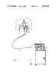
- FIG. 1is a schematic diagram of a ventricular assist system constructed in accordance with the invention
- FIGS. 2, 3 and 4are cross-sectional schematic views of a pump which may be used in the system of the invention, illustrating different pumping conditions;
- FIG. 5is a block diagram of a ventricular assist system constructed in accordance with the invention.
- FIG. 6is a series of plots illustrating the relationship of ventricular pressure to pump volume in various loading modes in the system of the invention.
- FIG. 7is a series of plots illustrating the relationship of ventricular pressure to pump volume under various contractility variants which may be present in a patient.
- the heart-assist system of the inventionoperates such that a pump connected to a left ventricle receives output therefrom.
- the pumpincludes an actuator which operates to cause the pump to conduct a fill cycle in which it receives output from the ventricle to which it is connected, and to conduct an eject cycle in which the contents of the pump are expelled into the patient's circulation.
- a controlis connected to the actuator for varying the time of initiation of at least one of the fill cycle and eject cycle in relation to systole of the ventricle to which the pump is connected to thereby vary the loading of such ventricle.
- the blood pump 1 of the system of the inventionis shown implanted within the body of a patient 2.
- the specific details of the blood pump 1will be described below.
- the blood pumpis connected to the left ventricle 3 of the patient via an inflow conduit 4 of a suitable material, such as woven dacron (a trademark), which pierces the pericardial portion of the patient's diaphragm 5.
- a suitable cannulanot shown
- An outflow conduit 6 of a suitable materialsuch as woven dacron (a trademark) connects the outflow of the pump 1 to the supraceliac aorta or other suitable systemic artery by an anastomosed graft.
- the implanted pumpis shown powered from an external console via percutaneous leads.
- other types of power sourcesincluding partially or fully implanted systems.
- Control and power leads for the implanted pump 1pass through a suitable biocompatible percutaneous vent sheath cable 7.
- the cable 7is connected via a suitable extension cable 8 to a control console 9.
- the control console 9powers and controls the implanted pump 1 and provides for monitoring critical system and patient parameters.
- the console 9includes a control panel 10 provided with a variety of suitable switches and knobs for setting system control modes and making parameter adjustments, as more fully described below.
- the control panelalso provides for the monitoring of patient and system parameters displayed via signals obtained from patient transducers, such as ECG, aortic and left ventricular pressures. These parameters may be obtained by means known to those skilled in the art. Additionally, the pump volume may be determined via sensors located in the pump as described below. Suitable alarm capabilities may also be utilized in the console to detect out-of-limit patient variables or malfunction in the pumping system. Appropriate redundancy may also be provided for reliability standards.
- the blood pump 1which is connected with the left ventricle 3 fills during left ventricular systole by offering low resistance to the outflow from the left ventricle through the inflow conduit 4.
- the pump 1begins an eject cycle in which it contracts, as will be explained below, to expel its contents through the outflow conduit 6 into the patient's circulatory system (via the supraceliac aorta in the arrangement illustrated).
- the eject cycleis initiated by energization of a solenoid in the pump actuator.
- Such energization signalsare provided from a suitable power supply in the console 9 (or from an implanted unit if desired).
- the system of the invention and the method of the inventionmay be employed, by way of example, in connection with a blood pump of the general type such as that described in U.S. Pat. Nos. 4,167,046 and 4,457,673, assigned to the assignee of the present invention.
- This type of pumpincludes a pair of opposed pusher plates which act on opposite sides of a disc-shaped seamless sac to expel fluid therefrom.
- Opposed beam springsare each pivotally connected at one end to the associated pusher plates and are attached at the other spring end on an armature assembly pivotally connected to a frame.
- Each assemblyincludes a preload stop which holds the associated spring in a relatively less stressed position. Coordinated movement of the two assemblies toward one another, by solenoid actuation, moves the two springs towards their relatively more stressed positions. Stress relief in the beam springs acts to move the two pusher plates symmetrically toward one another.
- the pump 1which is for the purpose of serving as a left ventricular device implanted in a human patient, includes an enclosure 11 defining a pumping chamber 13 (see FIGS. 2 through 4.) Opposed pusher plates 15, 17 are disposed on opposite sides of the enclosure 11 and are in contact therewith. Movement of the plates toward one another acts to compress the flexible enclosure and force the contents of the chamber out through a suitable outlet duct, not shown. Greater detail of this pump chamber configuration is given in the aforementioned U.S. patents.
- An annular support 19surrounds the flexible enclosure 11 to position it with respect to the remaining portions of the pump, including the actuator mechanism.
- the ends of beam springs 27 opposite ends 25are provided with portions 37 of slightly enlarged cross-section.
- the sections 37are bolted to a support 39 by bolts 41 passing through the portions 37 into the support 39.
- the ends of the beams 33 opposite the ends 31are provided with enlarged thickness portions 43 which are bolted to a support 45 by means of bolts 47.
- Each of the supports 39 and 45, respectively,is provided with a pair of arms 49 and 51, respectively, extending therefrom coextensively with the corresponding beam springs 27 and 33.
- Projections or preload stops 53are provided on the free ends of the arms 49 projecting under the corresponding one of the beam springs 27.
- Similar preload stops 55are provided on the free ends of the arms 51 projecting over the corresponding one of the beam springs 33.
- the mating surfaces of the portions 37 of the beam springs 27 and the support 39lie in a plane such that the engaging points of the preload stops 53 project beyond that plane and, accordingly, preload the beam springs 27 in bending stress.
- Each of the supports 39 and 45is mounted for pivotal movement about an axis through a pivot pin 57 and 59, respectively.
- the support 39pivots on the pin 57, so likewise do the sections 37 of the beam springs 27 move pivotally about the axis.
- the support 45pivots on the axis of the pin 59, so likewise the ends 43 of the beam springs 33 pivot about the axis of the pin 59 with the support 45.
- Each of the pins 57 and 59is supported in a frame 61 which comprises a portion of the general frame (not shown) of the pump which includes the enclosure support.
- solenoid meansFor the purpose of pivoting the beam springs about the axes of the pins 57 and 59, solenoid means are provided.
- the solenoid meansinclude a pair of solenoid armatures 63 and 65 mounted, respectively, on supports 39, 45.
- Solenoid armature 63includes a C-shaped core 67, the free ends of which extend through mating openings in the support 39.
- the solenoid armature 65includes a C-shaped core 69, the free ends of which extend through mating openings in the support 45.
- the open side of the core 67faces the open side of the core 69 and the free ends 79 are aligned.
- Each leg of the C-shaped core 67is wound by a coil 71 and 73.
- each leg of the C-shaped core 69is wound by a coil 75 and 77, respectively.
- Energization of the coils 71, 73, 75, and 77, by suitable control means, not shown,causes the ends of the solenoid cores to be attracted toward each other.
- FIG. 2illustrates the apparatus in a condition in which the pump chamber 13 is full and the solenoid armatures 63 and 65 are unenergized. In this condition, the arms 49 and 51 are swung open to their widest conditions as are the beam springs 27 and 33. In this condition, a preload bias is provided to the springs by the preload stops 53 and 55.
- the ejection strokeis begun when the power circuits 87 (FIG. 5) energize the solenoid coils 71, 73, 75, and 77.
- the armatures 63 and 65are drawn toward each other, moving the arms 49 and 51 to the position shown in FIG. 3.
- the inertia of the filled pump chamber 13 and compressible sac 11retain the ends 25 and 31 of the beam springs 27 and 23 essentially in the same position as in FIG. 2.
- the preload stops 53 and 55are moved away from the springs, with pivoting of supports 39, 45, causing the springs to be stressed to a more loaded condition in which they contain greater stored energy.
- the solenoid meansAfter closure to the position of FIG. 3, the solenoid means are held there by a relatively small latching current. If additional holding force is needed, a small permanent magnet may be used. The force of the latter may be overcome when necessary by a small reverse current in the solenoid coils.
- the apparatusis returned to the condition shown in FIG. 2 as the result of the cardiac systole.
- the solenoid gapthus increases as the supports 39 and 45 pivot about the pivot pins 57 and 59, respectively, as the plates 15 and 17 push out the ends 25 and 31 of the springs 27 and 33.
- FIG. 5a block diagram illustrating the relationship of the control console to the other elements of the system is shown.
- the control console 9is powered from a suitable AC power line 81 which supplies power to an uninterruptable power supply 83 of suitable conventional design.
- a standby battery 85is provided in the console 9 which is charged via the power supply 83 and which provides power through the power supply 83 in the event of failure of power from the AC power line 81.
- the power supply 83also provides power to the energy converter or solenoid means of the pump 1 via the cable connections 7, 8 through suitable power circuits 87 contained within the console 9.
- the power circuitsare shown in the same overall box or block as the control circuits 89 and the transducer circuits 91 to indicate the commonality of many portions of such circuits and their interconnection with the power supply 83 and with front panel components and physiology monitor indicated in the blocks 93 and 95.
- the power circuits, control circuits and transducer circuits 87, 89 and 91may also be connected, if desired, to a cathode ray tube display terminal 97 which may or may not be located on the front panel 10 of the control console 9.
- Patient signalssuch as ECG, aortic pressure, and left ventricle pressure, may be provided by appropriate and known transducers, indicated by the block 99, within the patient 2.
- the upper pair of curvescompares the ventricular pressure with the pump volume in an operating mode, known as the fill rate trigger mode, wherein essentially minimal loading of the ventricle occurs.
- the upper curve, 101represents ventricular pressure which may be seen to rise and fall during systole and remain at very low levels during diastole.
- the pump volumerepresented by the curve 103, increases from minimum to maximum during systole as the fill cycle is set to coincide with systole.
- an ejection cycleis initiated, expelling the contents of the pump during diastole of the ventricle to which the pump is attached.
- a second mode of loadingis illustrated by the middle pair of curves, with the curve 105 indicating the ventricular pressure and the curve 107 indicating the pump volume.
- this modeknown as the fill delay or early load mode
- the fill cycle of the pumpis delayed from the beginning of ventricular systole. This delay causes the ventricular pressure to increase during the isovolumic contraction phase (before the aortic valve opens) and consequently partially loads the ventricle.
- the solenoidis de-energized and the ventricle begins discharging into the pump, ventricular pressure is reduced. Solenoid de-energization will typically be set to occur prior to termination of the isovolumoic contraction phase.
- the duration of the higher pressure in the ventriclei.e., the width of the higher portion of the curve 105 during systole
- the degree of loading of the ventriclecan be varied to precisely control the degree of loading of the ventricle during each heart cycle.
- the lower pair of curves in FIG. 6represent a third loading mode, namely the eject early, or late systole load mode.
- the beginning of pump fill cycleis essentially coincident with the beginning of systole as was the case with the uppermost two curves, 101 in FIG. 6 and 113 in FIG. 7.
- the ventricular pressureas represented by the curve 109, is increased by beginning the ejection mode of the pump before conclusion of systole.
- pump volumerepresented by the curve 111
- amount of loadingas represented by the higher portion of the curve 109 during systole may be regulated.
- any suitable patient or pump system informationmay be employed.
- pump ejectionmay be triggered by the QRS complex of the patient's ECG, detected by a suitable ECG detection system capable of detecting the QRS complex. Since the QRS occurs at the start of ventricular systole, the actual initiation of pump ejection is delayed from this event until the end of systole by manually (or automatically) setting a particular preselected interval on the control console. By adjusting such timing of the energization of the solenoid operated pump, the pump phasing can be set to achieve a desired ventricular loading or unloading.
- ventricular systoleis sensed by utilizing a position sensor, shown schematically in FIGS. 2-4 at 110, suitably mounted within the pump, to detect the current volume of blood in the pump sac.
- Sensors for accomplishing thisare known in the art and typically are conventional eddy-current type position transducers. Such devices operate to measure the spacing between a current signaling surface and a target surface according to changes produced by magnetic induction in the target surface.
- Such detectorsare sold in combination with control circuitry and can be readily adapted to provide the desired information and fulfill size requirements.
- ventricular pressureis indicated by the curve 113 as contrasted with pump volume shown by the curve 115.
- the curve 113represents a ventricular pressure which is weak, such as might occur in a situation of a severely diseased heart.
- the ventricular pressurefalls off toward the end of systole, resulting in a significant falloff in the rate of increase of pump volume during that period.
- the timing of the ejection strokeis delayed from the falloff in ventricular pressure and consequent falloff in fill rate an interval (designated "t" in FIG. 7) sufficient to insure that the ejection cycle will occur during ventricular diastole.
- the pair of curves in the middle of FIG. 7indicate ventricular pressure 117 and pump volume 119 during a situation wherein there is strong ventricular contractility.
- the pump volumereaches its maximum capacity (full fill position) early, with the pump fill rate declining to zero even though vertricular systole has not ended.
- the zero pump fill ratewill falsely indicate the end of systole to the control system which is turn will initiate pump ejection prematurely.
- the co-pulsation of the pump and ventricle in such a caseincreases the load on the ventricle as shown in curve 117. In this sense, the situation is somewhat similar to that which occurs during the early eject or late load mode of operation illustrated by the lower two curves in FIG. 6.
- a lower level of loadingmay be achieved by placing a compliant stop in the pump as shown in FIGS. 2 through 5.
- the compliant stopas illustrated schematically, comprises a curved or C-shaped bracket 116 which is positioned so that its ends extend to locations over the posts 21 and 23. Pads 118 of a compressible material, such as an elastomeric, engage the ends of the posts in the filled position. Although some additional loading of the left ventricle is shown by the curve 121, the loading is lessened.
- the compliant stopprovides a slight mesa 123a on the curve 123 which last for a time t at an increased volume increment of ⁇ .
- the mesa 123acan be used by the pump position transducers to sense the end of systole when the down step on the backside of the mesa 123a occurs. This occurs when the pressure within the ventricle no longer overcomes the compliance of the compliant stop. By detecting the end of systole as described, the beginning of pump ejection can be regulated to eliminate co-pulsation between the ventricle and the pump to minimize ventricular loading.
- the system and method of the inventionrepresent a significant improvement in ventricular assist systems and methods in which synchronization with the natural heart phases is readily achieved and in which a precise degree of loading/unloading of the heart may be selected.
- Such loadingis useful to prevent atrophy of the heart muscle in the case of permanent circulatory support, or to help wean the patient from the assist device in the case of temporary use by enabling the heart to be gradually loaded in a controlled manner.
- the degree of phase overlapmay be controlled on either end of the ventricular systole to control the degree of ventricular loading.
Landscapes
- Health & Medical Sciences (AREA)
- Engineering & Computer Science (AREA)
- Heart & Thoracic Surgery (AREA)
- Cardiology (AREA)
- Hematology (AREA)
- Mechanical Engineering (AREA)
- Anesthesiology (AREA)
- Biomedical Technology (AREA)
- Life Sciences & Earth Sciences (AREA)
- Animal Behavior & Ethology (AREA)
- General Health & Medical Sciences (AREA)
- Public Health (AREA)
- Veterinary Medicine (AREA)
- Human Computer Interaction (AREA)
- Medical Informatics (AREA)
- External Artificial Organs (AREA)
Abstract
Description
Claims (18)
Priority Applications (9)
| Application Number | Priority Date | Filing Date | Title |
|---|---|---|---|
| US06/933,490US4756302A (en) | 1986-11-20 | 1986-11-20 | Blood pumping system and method |
| CA000551879ACA1277194C (en) | 1986-11-20 | 1987-11-16 | Blood pumping system and method |
| JP63500468AJP2532637B2 (en) | 1986-11-20 | 1987-11-19 | Blood pump device and method |
| BR8707535ABR8707535A (en) | 1986-11-20 | 1987-11-19 | BLOOD PUMPING SYSTEM AND PROCESS |
| DE3789665TDE3789665T2 (en) | 1986-11-20 | 1987-11-19 | BLOOD PUMP SYSTEM. |
| PCT/US1987/003060WO1988003784A1 (en) | 1986-11-20 | 1987-11-19 | Blood pumping system and method |
| EP88900184AEP0293436B1 (en) | 1986-11-20 | 1988-06-07 | Blood pumping system |
| AT8888900184TATE104534T1 (en) | 1986-11-20 | 1988-06-07 | BLOOD PUMP SYSTEM. |
| DK402288ADK402288D0 (en) | 1986-11-20 | 1988-07-19 | PROCEDURE AND APPARATUS FOR PUMPING BLOOD |
Applications Claiming Priority (1)
| Application Number | Priority Date | Filing Date | Title |
|---|---|---|---|
| US06/933,490US4756302A (en) | 1986-11-20 | 1986-11-20 | Blood pumping system and method |
Publications (1)
| Publication Number | Publication Date |
|---|---|
| US4756302Atrue US4756302A (en) | 1988-07-12 |
Family
ID=25464064
Family Applications (1)
| Application Number | Title | Priority Date | Filing Date |
|---|---|---|---|
| US06/933,490Expired - LifetimeUS4756302A (en) | 1986-11-20 | 1986-11-20 | Blood pumping system and method |
Country Status (8)
| Country | Link |
|---|---|
| US (1) | US4756302A (en) |
| EP (1) | EP0293436B1 (en) |
| JP (1) | JP2532637B2 (en) |
| BR (1) | BR8707535A (en) |
| CA (1) | CA1277194C (en) |
| DE (1) | DE3789665T2 (en) |
| DK (1) | DK402288D0 (en) |
| WO (1) | WO1988003784A1 (en) |
Cited By (25)
| Publication number | Priority date | Publication date | Assignee | Title |
|---|---|---|---|---|
| US5007927A (en)* | 1989-10-24 | 1991-04-16 | Purdue Research Foundation | Muscle-powered cardiac assist device |
| US5092879A (en)* | 1988-02-17 | 1992-03-03 | Jarvik Robert K | Intraventricular artificial hearts and methods of their surgical implantation and use |
| US5344385A (en)* | 1991-09-30 | 1994-09-06 | Thoratec Laboratories Corporation | Step-down skeletal muscle energy conversion system |
| US6123726A (en)* | 1997-07-25 | 2000-09-26 | Seiko Epson Corporation | Portable drive system for artificial heart |
| US6200260B1 (en) | 1997-10-09 | 2001-03-13 | Fore Flow Corporation | Implantable heart assist system |
| US6387037B1 (en) | 1997-10-09 | 2002-05-14 | Orqis Medical Corporation | Implantable heart assist system and method of applying same |
| US6390969B1 (en) | 1997-10-09 | 2002-05-21 | Orqis Medical Corporation | Implantable heart assist system and method of applying same |
| US20030069468A1 (en)* | 1997-10-09 | 2003-04-10 | Bolling Steven F. | Implantable heart assist system and method of applying same |
| US6610004B2 (en) | 1997-10-09 | 2003-08-26 | Orqis Medical Corporation | Implantable heart assist system and method of applying same |
| US20040230089A1 (en)* | 2003-05-15 | 2004-11-18 | Emilio Sacristan | Air-pressure powered driver for pneumatic ventricular assist devices |
| US20050085683A1 (en)* | 2003-10-15 | 2005-04-21 | Bolling Steven F. | Implantable heart assist system and method of applying same |
| US20050131385A1 (en)* | 2003-12-12 | 2005-06-16 | Bolling Steven F. | Cannulae for selectively enhancing blood flow |
| US20060036126A1 (en)* | 2004-08-16 | 2006-02-16 | Jeffrey Ross | Method and apparatus for modulating cellular growth and regeneration using ventricular assist device |
| US20060054485A1 (en)* | 2004-09-14 | 2006-03-16 | Mcgonigle John M | Solar/heat powered distillation device |
| WO2006135802A3 (en)* | 2005-06-09 | 2007-06-21 | World Heart Corp | Electromagnetic drive for a ventricular assist device |
| US20080045777A1 (en)* | 2005-06-09 | 2008-02-21 | Jal Jassawalla | Electromagnetic drive for a ventricular assist device |
| US7445592B2 (en) | 2004-06-10 | 2008-11-04 | Orqis Medical Corporation | Cannulae having reduced flow resistance |
| WO2009118499A1 (en)* | 2008-03-26 | 2009-10-01 | Cardio Assist Limited | Heart assist device |
| US9155827B2 (en) | 2010-02-17 | 2015-10-13 | Flow Forward Medical, Inc. | System and method to increase the overall diameter of veins |
| US9539380B2 (en) | 2011-08-17 | 2017-01-10 | Flow Forward Medical, Inc. | System and method to increase the overall diameter of veins and arteries |
| US9555174B2 (en) | 2010-02-17 | 2017-01-31 | Flow Forward Medical, Inc. | Blood pump systems and methods |
| US9662431B2 (en) | 2010-02-17 | 2017-05-30 | Flow Forward Medical, Inc. | Blood pump systems and methods |
| US10258730B2 (en) | 2012-08-17 | 2019-04-16 | Flow Forward Medical, Inc. | Blood pump systems and methods |
| US10426878B2 (en) | 2011-08-17 | 2019-10-01 | Flow Forward Medical, Inc. | Centrifugal blood pump systems |
| US11534593B2 (en) | 2016-04-29 | 2022-12-27 | Artio Medical, Inc. | Conduit tips and systems and methods for use |
Families Citing this family (3)
| Publication number | Priority date | Publication date | Assignee | Title |
|---|---|---|---|---|
| WO1991012035A1 (en)* | 1990-02-09 | 1991-08-22 | Teracor | Method and device for flow control of a periodic flow heart prosthesis |
| FR2658079B1 (en)* | 1990-02-09 | 1992-06-12 | Teracor | METHOD AND DEVICE FOR REGULATING A PERIODIC FLOW HEART PROSTHESIS BY MONITORING THE ACTUATOR CURRENT. |
| US7396327B2 (en) | 2002-01-07 | 2008-07-08 | Micromed Technology, Inc. | Blood pump system and method of operation |
Citations (13)
| Publication number | Priority date | Publication date | Assignee | Title |
|---|---|---|---|---|
| US3911898A (en)* | 1974-04-05 | 1975-10-14 | Jr Frank A Leachman | Heart assist method and device |
| US3966358A (en)* | 1973-11-09 | 1976-06-29 | Medac Gesellschaft Fur Klinische Spezialpraparate Mbh | Pump assembly |
| US4046137A (en)* | 1976-08-11 | 1977-09-06 | Avco Corporation | Solenoid operated blood pump drive system |
| US4143661A (en)* | 1977-12-12 | 1979-03-13 | Andros Incorporated | Power supply for body implant and method for operation |
| US4152786A (en)* | 1977-12-12 | 1979-05-08 | Andros Incorporated | Compensator for implanted blood pump |
| US4167046A (en)* | 1977-12-12 | 1979-09-11 | Andros, Inc. | Blood pumping device |
| US4175264A (en)* | 1975-03-06 | 1979-11-20 | Peter Schiff | Electronic synchronizer-monitor system for controlling the timing of mechanical assistance and pacing of the heart |
| US4384829A (en)* | 1980-11-28 | 1983-05-24 | Andros Incorporated | Pump and actuator mechanism |
| US4457673A (en)* | 1980-11-28 | 1984-07-03 | Novacor Medical Corporation | Pump and actuator mechanism |
| US4565497A (en)* | 1982-12-03 | 1986-01-21 | Novacor Medical Corporation | Pump actuator |
| US4611578A (en)* | 1983-05-03 | 1986-09-16 | Forschungsgesellschaft fur Biomedizinischs Technik E.V. Goethestrasse | Redundant piston pump for the operation of single or multiple chambered pneumatic blood pumps |
| US4662358A (en)* | 1984-04-17 | 1987-05-05 | Thoratec Laboratories Corporation | Electronic control system for a cardiac prosthesis |
| US4666443A (en)* | 1986-04-18 | 1987-05-19 | Novacor Medical Corporation | Biventricular circulatory assist system and method |
- 1986
- 1986-11-20USUS06/933,490patent/US4756302A/ennot_activeExpired - Lifetime
- 1987
- 1987-11-16CACA000551879Apatent/CA1277194C/ennot_activeExpired - Lifetime
- 1987-11-19JPJP63500468Apatent/JP2532637B2/ennot_activeExpired - Lifetime
- 1987-11-19DEDE3789665Tpatent/DE3789665T2/ennot_activeExpired - Fee Related
- 1987-11-19BRBR8707535Apatent/BR8707535A/enunknown
- 1987-11-19WOPCT/US1987/003060patent/WO1988003784A1/enactiveIP Right Grant
- 1988
- 1988-06-07EPEP88900184Apatent/EP0293436B1/ennot_activeExpired - Lifetime
- 1988-07-19DKDK402288Apatent/DK402288D0/ennot_activeApplication Discontinuation
Patent Citations (13)
| Publication number | Priority date | Publication date | Assignee | Title |
|---|---|---|---|---|
| US3966358A (en)* | 1973-11-09 | 1976-06-29 | Medac Gesellschaft Fur Klinische Spezialpraparate Mbh | Pump assembly |
| US3911898A (en)* | 1974-04-05 | 1975-10-14 | Jr Frank A Leachman | Heart assist method and device |
| US4175264A (en)* | 1975-03-06 | 1979-11-20 | Peter Schiff | Electronic synchronizer-monitor system for controlling the timing of mechanical assistance and pacing of the heart |
| US4046137A (en)* | 1976-08-11 | 1977-09-06 | Avco Corporation | Solenoid operated blood pump drive system |
| US4143661A (en)* | 1977-12-12 | 1979-03-13 | Andros Incorporated | Power supply for body implant and method for operation |
| US4167046A (en)* | 1977-12-12 | 1979-09-11 | Andros, Inc. | Blood pumping device |
| US4152786A (en)* | 1977-12-12 | 1979-05-08 | Andros Incorporated | Compensator for implanted blood pump |
| US4384829A (en)* | 1980-11-28 | 1983-05-24 | Andros Incorporated | Pump and actuator mechanism |
| US4457673A (en)* | 1980-11-28 | 1984-07-03 | Novacor Medical Corporation | Pump and actuator mechanism |
| US4565497A (en)* | 1982-12-03 | 1986-01-21 | Novacor Medical Corporation | Pump actuator |
| US4611578A (en)* | 1983-05-03 | 1986-09-16 | Forschungsgesellschaft fur Biomedizinischs Technik E.V. Goethestrasse | Redundant piston pump for the operation of single or multiple chambered pneumatic blood pumps |
| US4662358A (en)* | 1984-04-17 | 1987-05-05 | Thoratec Laboratories Corporation | Electronic control system for a cardiac prosthesis |
| US4666443A (en)* | 1986-04-18 | 1987-05-19 | Novacor Medical Corporation | Biventricular circulatory assist system and method |
Cited By (57)
| Publication number | Priority date | Publication date | Assignee | Title |
|---|---|---|---|---|
| US5092879A (en)* | 1988-02-17 | 1992-03-03 | Jarvik Robert K | Intraventricular artificial hearts and methods of their surgical implantation and use |
| US5007927A (en)* | 1989-10-24 | 1991-04-16 | Purdue Research Foundation | Muscle-powered cardiac assist device |
| US5344385A (en)* | 1991-09-30 | 1994-09-06 | Thoratec Laboratories Corporation | Step-down skeletal muscle energy conversion system |
| US5653676A (en)* | 1991-09-30 | 1997-08-05 | Thoratec Laboratories Corporation | Step-down skeletal muscle energy conversion method |
| US5701919A (en)* | 1991-09-30 | 1997-12-30 | Thoratec Laboratories Corporation | Step-down skeletal muscle energy conversion system |
| US5984857A (en)* | 1991-09-30 | 1999-11-16 | Thoratec Laboratories Corporation | Step-down skeletal muscle energy conversion system |
| US6123726A (en)* | 1997-07-25 | 2000-09-26 | Seiko Epson Corporation | Portable drive system for artificial heart |
| US6685621B2 (en) | 1997-10-09 | 2004-02-03 | Orois Medical Corporation | Implantable heart assist system and method of applying same |
| US7614997B2 (en) | 1997-10-09 | 2009-11-10 | Orqis Medical Corporation | Implantable heart assist system and method of applying same |
| US6387037B1 (en) | 1997-10-09 | 2002-05-14 | Orqis Medical Corporation | Implantable heart assist system and method of applying same |
| US6390969B1 (en) | 1997-10-09 | 2002-05-21 | Orqis Medical Corporation | Implantable heart assist system and method of applying same |
| US6428464B1 (en) | 1997-10-09 | 2002-08-06 | Orqis Medical Corporation | Implantable heart assist system |
| US20030069468A1 (en)* | 1997-10-09 | 2003-04-10 | Bolling Steven F. | Implantable heart assist system and method of applying same |
| US6610004B2 (en) | 1997-10-09 | 2003-08-26 | Orqis Medical Corporation | Implantable heart assist system and method of applying same |
| US6200260B1 (en) | 1997-10-09 | 2001-03-13 | Fore Flow Corporation | Implantable heart assist system |
| US20040116768A1 (en)* | 1997-10-09 | 2004-06-17 | Bolling Steven F. | Implantable heart assist system and method of applying same |
| US8900115B2 (en) | 1997-10-09 | 2014-12-02 | Thoratec Corporation | Implantable heart assist system and method of applying same |
| US7993260B2 (en) | 1997-10-09 | 2011-08-09 | Thoratec Corporation | Implantable heart assist system and method of applying same |
| US6299575B1 (en) | 1997-10-09 | 2001-10-09 | Orqis Medical Corporation | Implantable heart assist system |
| US6889082B2 (en) | 1997-10-09 | 2005-05-03 | Orqis Medical Corporation | Implantable heart assist system and method of applying same |
| US7591778B2 (en) | 1997-10-09 | 2009-09-22 | Orqis Medical Corporation | Implantable heart assist system and method of applying same |
| US20050256363A1 (en)* | 1997-10-09 | 2005-11-17 | Bolling Steven F | Implantable heart assist system and method of applying same |
| US7588531B2 (en) | 1997-10-09 | 2009-09-15 | Orqis Medical Corporation | Implantable heart assist system and method of applying same |
| US7513863B2 (en) | 1997-10-09 | 2009-04-07 | Orqis Medical Corporation | Implantable heart assist system and method of applying same |
| US7458929B2 (en) | 1997-10-09 | 2008-12-02 | Orqis Medical Corporation | Implantable heart assist system and method of applying same |
| US7125376B2 (en) | 1997-10-09 | 2006-10-24 | Orqis Medical Corporation | Implantable heart assist system and method of applying same |
| US7144365B2 (en) | 1997-10-09 | 2006-12-05 | Orqis Medical Corporation | Implantable heart assist system and method of applying same |
| US20060276681A1 (en)* | 1997-10-09 | 2006-12-07 | Bolling Steven F | Implantable heart assist system and method of applying same |
| US7331921B2 (en) | 2002-02-15 | 2008-02-19 | Orqis Medical Corporation | Implantable heart assist system and method of applying same |
| US20040236173A1 (en)* | 2002-02-15 | 2004-11-25 | Anthony Viole | Implantable heart assist system and method of applying same |
| US20040230089A1 (en)* | 2003-05-15 | 2004-11-18 | Emilio Sacristan | Air-pressure powered driver for pneumatic ventricular assist devices |
| US7074176B2 (en) | 2003-05-15 | 2006-07-11 | Innovamedica S.A. De C.V. | Air-pressure powered driver for pneumatic ventricular assist devices |
| US20050085683A1 (en)* | 2003-10-15 | 2005-04-21 | Bolling Steven F. | Implantable heart assist system and method of applying same |
| US20050131385A1 (en)* | 2003-12-12 | 2005-06-16 | Bolling Steven F. | Cannulae for selectively enhancing blood flow |
| US7445592B2 (en) | 2004-06-10 | 2008-11-04 | Orqis Medical Corporation | Cannulae having reduced flow resistance |
| US20060036126A1 (en)* | 2004-08-16 | 2006-02-16 | Jeffrey Ross | Method and apparatus for modulating cellular growth and regeneration using ventricular assist device |
| US7828711B2 (en) | 2004-08-16 | 2010-11-09 | Cardiac Pacemakers, Inc. | Method and apparatus for modulating cellular growth and regeneration using ventricular assist device |
| US20060054485A1 (en)* | 2004-09-14 | 2006-03-16 | Mcgonigle John M | Solar/heat powered distillation device |
| US20080045777A1 (en)* | 2005-06-09 | 2008-02-21 | Jal Jassawalla | Electromagnetic drive for a ventricular assist device |
| WO2006135802A3 (en)* | 2005-06-09 | 2007-06-21 | World Heart Corp | Electromagnetic drive for a ventricular assist device |
| US9333284B2 (en)* | 2008-03-26 | 2016-05-10 | Heart Biotech Limited | Heart assist device |
| WO2009118499A1 (en)* | 2008-03-26 | 2009-10-01 | Cardio Assist Limited | Heart assist device |
| US20110071337A1 (en)* | 2008-03-26 | 2011-03-24 | Cardio Assist Ltd. | Heart assist device |
| US20130289335A1 (en)* | 2008-03-26 | 2013-10-31 | Cardio Assist Ltd. | Heart assist device |
| US9155827B2 (en) | 2010-02-17 | 2015-10-13 | Flow Forward Medical, Inc. | System and method to increase the overall diameter of veins |
| US9555174B2 (en) | 2010-02-17 | 2017-01-31 | Flow Forward Medical, Inc. | Blood pump systems and methods |
| US9662431B2 (en) | 2010-02-17 | 2017-05-30 | Flow Forward Medical, Inc. | Blood pump systems and methods |
| US10293089B2 (en) | 2010-02-17 | 2019-05-21 | Flow Forward Medical, Inc. | System and method to increase the overall diameter of veins |
| US10376629B2 (en) | 2010-02-17 | 2019-08-13 | Flow Forward Medical, Inc. | Methods to increase the overall diameter of donating veins and arteries |
| US10537674B2 (en) | 2010-02-17 | 2020-01-21 | Flow Forward Medical, Inc. | System and method to increase the overall diameter of veins |
| US11724018B2 (en) | 2010-02-17 | 2023-08-15 | Artio Medical, Inc. | System and method to increase the overall diameter of veins |
| US9539380B2 (en) | 2011-08-17 | 2017-01-10 | Flow Forward Medical, Inc. | System and method to increase the overall diameter of veins and arteries |
| US10426878B2 (en) | 2011-08-17 | 2019-10-01 | Flow Forward Medical, Inc. | Centrifugal blood pump systems |
| US11400275B2 (en) | 2011-08-17 | 2022-08-02 | Artio Medical, Inc. | Blood pump system for causing persistent increase in the overall diameter of a target vessel |
| US10258730B2 (en) | 2012-08-17 | 2019-04-16 | Flow Forward Medical, Inc. | Blood pump systems and methods |
| US11160914B2 (en) | 2012-08-17 | 2021-11-02 | Artio Medical, Inc. | Blood pump systems and methods |
| US11534593B2 (en) | 2016-04-29 | 2022-12-27 | Artio Medical, Inc. | Conduit tips and systems and methods for use |
Also Published As
| Publication number | Publication date |
|---|---|
| EP0293436A4 (en) | 1989-11-14 |
| DE3789665D1 (en) | 1994-05-26 |
| BR8707535A (en) | 1989-02-21 |
| JPH01501373A (en) | 1989-05-18 |
| DE3789665T2 (en) | 1994-08-25 |
| JP2532637B2 (en) | 1996-09-11 |
| DK402288A (en) | 1988-07-19 |
| CA1277194C (en) | 1990-12-04 |
| EP0293436B1 (en) | 1994-04-20 |
| EP0293436A1 (en) | 1988-12-07 |
| DK402288D0 (en) | 1988-07-19 |
| WO1988003784A1 (en) | 1988-06-02 |
Similar Documents
| Publication | Publication Date | Title |
|---|---|---|
| US4756302A (en) | Blood pumping system and method | |
| JP7557511B2 (en) | Assist artificial heart and its control device | |
| US3911898A (en) | Heart assist method and device | |
| US4666443A (en) | Biventricular circulatory assist system and method | |
| US6406422B1 (en) | Ventricular-assist method and apparatus | |
| US3911897A (en) | Heart assist device | |
| US7614998B2 (en) | Fully-implantable cardiac recovery system | |
| US6511413B2 (en) | Single cannula ventricular-assist method and apparatus | |
| EP0078090B1 (en) | Method and device for controlling the cuff pressure in measuring the blood pressure in a finger by means of a photo-electric plethysmograph | |
| CA2368200C (en) | Implantable ventricular assist device | |
| JP2004510482A (en) | Apparatus for controlling a cardiac assist device | |
| CA2506758A1 (en) | Miniature, pulsatile implantable ventricular assist devices and methods of controlling ventricular assist devices | |
| JPH025966A (en) | Embedding artificial heart | |
| JPH07308376A (en) | Pump for circulation assisting equipment | |
| Branch et al. | A synchronous control system for a totally implanted circulatory assist device | |
| Portner | The Novacor heart assist system: Development, testing and initial clinical evaluation | |
| EP0293421A1 (en) | Implantable biventricular circulatory support system | |
| SU925348A1 (en) | Auxiliary blood circulation apparatus | |
| Portner¹ | 10. The Novacor heart assist system: Development, testing and initial clinical | |
| JPH0197470A (en) | Control of pump for artificial heart |
Legal Events
| Date | Code | Title | Description |
|---|---|---|---|
| AS | Assignment | Owner name:NOVACOR MEDICAL CORPORATION, 7799 PARDEE LANE, OAK Free format text:ASSIGNMENT OF ASSIGNORS INTEREST.;ASSIGNORS:PORTNER, PEER M.;JASSAWALLA, JAL S.;MILLER, PHILLIP J.;REEL/FRAME:004632/0028;SIGNING DATES FROM 19861103 TO 19861105 Owner name:NOVACOR MEDICAL CORPORATION,CALIFORNIA Free format text:ASSIGNMENT OF ASSIGNORS INTEREST;ASSIGNORS:PORTNER, PEER M.;JASSAWALLA, JAL S.;MILLER, PHILLIP J.;SIGNING DATES FROM 19861103 TO 19861105;REEL/FRAME:004632/0028 | |
| STCF | Information on status: patent grant | Free format text:PATENTED CASE | |
| AS | Assignment | Owner name:BAXTER INTERNATIONAL INC., ILLINOIS Free format text:ASSIGNMENT OF ASSIGNORS INTEREST.;ASSIGNOR:NOVACOR MEDICAL CORPORATION;REEL/FRAME:005132/0131 Effective date:19890630 | |
| FEPP | Fee payment procedure | Free format text:PAT HLDR NO LONGER CLAIMS SMALL ENT STAT AS SMALL BUSINESS (ORIGINAL EVENT CODE: LSM2); ENTITY STATUS OF PATENT OWNER: LARGE ENTITY | |
| FEPP | Fee payment procedure | Free format text:PAYOR NUMBER ASSIGNED (ORIGINAL EVENT CODE: ASPN); ENTITY STATUS OF PATENT OWNER: LARGE ENTITY | |
| FPAY | Fee payment | Year of fee payment:4 | |
| FEPP | Fee payment procedure | Free format text:PAYER NUMBER DE-ASSIGNED (ORIGINAL EVENT CODE: RMPN); ENTITY STATUS OF PATENT OWNER: LARGE ENTITY Free format text:PAYOR NUMBER ASSIGNED (ORIGINAL EVENT CODE: ASPN); ENTITY STATUS OF PATENT OWNER: LARGE ENTITY | |
| FPAY | Fee payment | Year of fee payment:8 | |
| FPAY | Fee payment | Year of fee payment:12 | |
| AS | Assignment | Owner name:EDWARDS LIFESCIENCES CORPORATION, CALIFORNIA Free format text:ASSIGNMENT OF ASSIGNORS INTEREST;ASSIGNOR:BAXTER INTERNATIONAL INC.;REEL/FRAME:010901/0274 Effective date:20000609 | |
| AS | Assignment | Owner name:WORLD HEART CORPORATION, CALIFORNIA Free format text:ASSIGNMENT OF ASSIGNORS INTEREST;ASSIGNOR:EDWARDS LIFESCIENCES CORPORATION;REEL/FRAME:012967/0915 Effective date:20020516 |