US4756198A - Sensor apparatus for mass flow rate measurement system - Google Patents
Sensor apparatus for mass flow rate measurement systemDownload PDFInfo
- Publication number
- US4756198A US4756198AUS07/013,768US1376887AUS4756198AUS 4756198 AUS4756198 AUS 4756198AUS 1376887 AUS1376887 AUS 1376887AUS 4756198 AUS4756198 AUS 4756198A
- Authority
- US
- United States
- Prior art keywords
- loops
- loop
- flow rate
- mass flow
- recited
- Prior art date
- Legal status (The legal status is an assumption and is not a legal conclusion. Google has not performed a legal analysis and makes no representation as to the accuracy of the status listed.)
- Expired - Lifetime
Links
Images


Classifications
- G—PHYSICS
- G01—MEASURING; TESTING
- G01F—MEASURING VOLUME, VOLUME FLOW, MASS FLOW OR LIQUID LEVEL; METERING BY VOLUME
- G01F1/00—Measuring the volume flow or mass flow of fluid or fluent solid material wherein the fluid passes through a meter in a continuous flow
- G01F1/76—Devices for measuring mass flow of a fluid or a fluent solid material
- G01F1/78—Direct mass flowmeters
- G01F1/80—Direct mass flowmeters operating by measuring pressure, force, momentum, or frequency of a fluid flow to which a rotational movement has been imparted
- G01F1/84—Coriolis or gyroscopic mass flowmeters
- G01F1/8409—Coriolis or gyroscopic mass flowmeters constructional details
- G01F1/8422—Coriolis or gyroscopic mass flowmeters constructional details exciters
- G—PHYSICS
- G01—MEASURING; TESTING
- G01F—MEASURING VOLUME, VOLUME FLOW, MASS FLOW OR LIQUID LEVEL; METERING BY VOLUME
- G01F1/00—Measuring the volume flow or mass flow of fluid or fluent solid material wherein the fluid passes through a meter in a continuous flow
- G01F1/76—Devices for measuring mass flow of a fluid or a fluent solid material
- G01F1/78—Direct mass flowmeters
- G01F1/80—Direct mass flowmeters operating by measuring pressure, force, momentum, or frequency of a fluid flow to which a rotational movement has been imparted
- G01F1/84—Coriolis or gyroscopic mass flowmeters
- G01F1/8409—Coriolis or gyroscopic mass flowmeters constructional details
- G01F1/8427—Coriolis or gyroscopic mass flowmeters constructional details detectors
- G—PHYSICS
- G01—MEASURING; TESTING
- G01F—MEASURING VOLUME, VOLUME FLOW, MASS FLOW OR LIQUID LEVEL; METERING BY VOLUME
- G01F1/00—Measuring the volume flow or mass flow of fluid or fluent solid material wherein the fluid passes through a meter in a continuous flow
- G01F1/76—Devices for measuring mass flow of a fluid or a fluent solid material
- G01F1/78—Direct mass flowmeters
- G01F1/80—Direct mass flowmeters operating by measuring pressure, force, momentum, or frequency of a fluid flow to which a rotational movement has been imparted
- G01F1/84—Coriolis or gyroscopic mass flowmeters
- G01F1/845—Coriolis or gyroscopic mass flowmeters arrangements of measuring means, e.g., of measuring conduits
- G01F1/8468—Coriolis or gyroscopic mass flowmeters arrangements of measuring means, e.g., of measuring conduits vibrating measuring conduits
- G01F1/8481—Coriolis or gyroscopic mass flowmeters arrangements of measuring means, e.g., of measuring conduits vibrating measuring conduits having loop-shaped measuring conduits, e.g. the measuring conduits form a loop with a crossing point
- G01F1/8486—Coriolis or gyroscopic mass flowmeters arrangements of measuring means, e.g., of measuring conduits vibrating measuring conduits having loop-shaped measuring conduits, e.g. the measuring conduits form a loop with a crossing point with multiple measuring conduits
Definitions
- a second U-shaped tubeis substituted for the spring arm and the two tubes are driven relative to each other.
- a magnetis affixed to one of the arms and a magnetic driving means is affixed to the other for interacting with the magnet and applying driving forces between the two tubes.
- flags or magnetsare similarly affixed to points on one of the tubes and sensing detectors or coils are correspondingly affixed to the other tube such that relative motion therebetween is sensed by the EMF induced in the sensing windings.
- Both the drive and sensing elementsobviously have mass, and in some cases such mass can have a significant impact on the dynamic response characteristics of the structure.
- conductive wiresare typically glued or taped directly to the tubes or other vibrating parts of the sensor and extended therealong to the tube mounting points for distribution to an electronic control and detection part of the system.
- Thisgives rise to disadvantages in addition to mass related effects in that the wires and their attachment means are subject to detachment as the tubes are vibrated during operation.
- the conductivity of the conductorsmay even be influenced by the temperature of the material flowing through the tubes.
- the relationship between the natural frequency of the drive mode (W D ) and the natural frequency of the Coriolis mode (W C )are predetermined by the particular vibrational characteristics of the structure.
- Such a relationshipcan be graphically expressed in a Coriolis mode resonance diagram of the type shown in FIG. 6 of the drawing wherein the mechanical amplification factor H is plotted against the ratio of W D to W C .
- the amplification factor (proportional to the sensitivity to mass flow rate) of the deviceis determined by the point at which the drive frequency W D falls on the curve C.
- the frequencies W D and W Cwill change somewhat with changes in density of the mass flow through the tube, it can be expected that the sensitivity of the device will also change with density. This is undesirable because it can lead to substantial inaccuracies where large swings in density are encountered.
- Another object of the present inventionis to provide an improved dual-tube device of the type described wherein the tube mass is reduced to its lowest practical level, and only light weight magnets and attaching fixtures are affixed thereto for accomplishing drive and sensing functions.
- Still another object of the present inventionis to provide a device of the type described wherein all drive and sensing windings, as well as associated connecting wires, are carried directly by the tube supporting casing.
- Another object of the present inventionis to provide an improved dual-tube device of the type described wherein the tube mass is reduced to its lowest practical level and resilient means is added to increase the sensitivity of the device without substantially affecting the mass of the structure.
- Still another object of the present inventionis to provide a device of the type described wherein means is added to the tube structure to move the drive mode natural frequency (W D ) closer to the Coriolis mode frequency (W C ) without changing the Coriolis frequency.
- a preferred embodimentincludes a dual-tube structure in which each tube is formed into a full loop and the loops are connected either in series or in parallel flow relationship.
- the loopsare elongated in the direction of the external flow line.
- Light weight magnetsare affixed to the tubes, a drive coil associated with two of the magnets is disposed between the tubes at a point midway between the loop extremities and opposite the cross-over points of the loops, and sensor windings associated with the remaining magnets are placed between the loops at each extremity thereof. No electrical connections need be carried by either loop.
- the sensitivity of the devicemay be further improved by coupling a resilient linking member between the tubes at their drive points.
- the linking memberhas the effect of increasing the spring constants of the loops in the drive mode without affecting the spring constants in the Coriolis mode.
- the present inventionprovides a device having increased sensitivity to mass flow rate, and increased utility in that the measurement range of the device is broadened to include the ability to measure small mass flow rates; as in the case of low liquid flow rates or gases.
- Another advantage of the present inventionis that the device may be implemented using tubing of very small diameter.
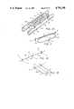
- FIG. 1is a partially broken longitudinal side view illustrating a dual loop mass flow rate sensor in accordance with the present invention
- FIG. 2is a partially broken top view thereof
- FIG. 3is a partially broken cross section taken along the line 3--3 of FIG. 2;
- FIG. 4is a broken partial elevation taken generally along the longitudinal center line of the device and illustrating an alternative sensing winding and magnet embodiment
- FIG. 5is an illustrative schematically depicting a serially configured dual loop alternative embodiment.
- FIG. 6is a diagram illustrating a typical resonance characteristic of a Coriolis flow meter
- FIG. 7is a partially broken cross section taken along the line 3--3 of FIG. 2 further showing the addition of a resilient linking member in accordance with the present invention
- FIG. 8illustrates a first alternative embodiment of a resilient member
- FIG. 9illustrates a second alternative embodiment of a resilient member
- FIG. 10illustrates a third alternative embodiment of a resilient member
- FIG. 11, 12 and 13are diagrams schematically illustrating three types of flow tubes that may be modified in accordance with the present invention.
- FIGS. 1-3 of the drawingthere are shown in partially broken side, top and cross sectional views, a presently preferred embodiment of a Coriolis mass flow rate sensor including a pair of elongated, generally helically configured tubes 10 and 12 of the type disclosed in the above-referenced copending application, Ser. No. 777,707.
- the tubesare supported by a base 14 comprised of input and output flow splitters 16 and 18 coupled together by a pair of longitudinal stiffener members 20 and 22 which are generally L-shaped in transverse cross section.
- the ends of the tube 10 and 12are connected to flow splitters 16 and 18 by suitable stress relieving fixtures 24 and are typically welded or brazed thereto.
- suitable stress relieving fixtures 24are typically welded or brazed thereto.
- a cross plate 26Welded to the top members 20 and 22 is a cross plate 26. Secured to plate 26 by means of suitable bolts, screws or other fasteners is a drive coil mount 32 and a pair of sensor coil support arms 34 and 36. Attached to the top of mount 32 is an electromagnetic driver means 38 including a pair of magnetic windings 40 and 42 wound about an axis extending transverse to the axes of the proximate portions of the tubes (at drive points D1 and D2). Disposed opposite the ends of driver means 38, and affixed to tubes 10 and 12 by suitable lightweight brackets 44 and 46, are lightweight permanent magnets 48 and 50 which are attracted or repelled by magnetic fields developed by drive currents in the windings 40 and 42. Brackets 44 and 46 are affixed to tubes 10 and 12 respectively, by welding or brazing at the drive points D1 and D2.
- Attached to the support arms 34 and 36are a pair of sensor windings 60 and 62 which are disposed between the extremities of the loops formed by tubes 10 and 12.
- the windings 60 and 62are wound about axes extending substantially parallel to tangents to the loop ends of the tubes at their sense points S1-S2 and S3-S4.
- Affixed to each of the tubes immediately adjacent windings 60 and 62are light-weight brackets 64-70 each of which carry a pair of light-weight magnets 72 and 74 (see FIG. 3) that are disposed on opposite sides of an arcuate portion of the windings 60.
- the sensing windings 62 and associated tube carried magnets, disposed at the other loop extremity,are similarly configured.
- the tube drive points D1 and D2will be caused to move toward and away from each other in responsive motion and, as is well explained in the prior art, mass flowing through the tubes will cause Coriolis force couples to be developed in each loop, tending to twist each loop, and alternately expanding and contracting the dynamic separation between the respective loop extremities caused in the first instance by the drive forces.
- the Coriolis motionis thus superimposed upon the drive motion. Accordingly, one pair of loop extremities will be out of phase relative to the other pair of loop extremities by a phase angle that is a function of the rate of mass flow through the tubes 10 and 12.
- Relative velocity of the separational motion at the opposite ends of the loopsis sensed by the windings 60 and 62 and fed to appropriate detection circuitry which measures the phase difference between the two signals as an indication of the mass flow rate through the dual-loop sensor.
- FIG. 4an alternative sensor configuration is depicted in part to show that the magnets 73 and 75 and their associated field can be rotated 90° relative to that of the previously described embodiment so long as the corresponding sensing winding 61 is likewise rotated.
- the axis of winding 61is parallel to the direction of the magnetic field created between magnets 73 and 75 and orthogonal to tangents to the tubes 10 and 12 at the points of attachment of the magnets.
- FIG. 5is included to show that as an alternative to the parallel flow embodiment depicted in FIGS. 1-3, a dual-loop serial flow embodiment is also possible. As indicated, flow material passing through the first loop 80 then passes through the second loop 82 before being emitted from the sensor structure. For simplicity, the driving and motion sensing components depicted in FIGS. 1-4 have been omitted.
- FIGS. 7-10additional means that may be added to improve the sensitivity of the above depicted embodiments are illustrated. Specifically referring now to FIG. 7, positioned immediately above the drive 38 and rigidly affixed to brackets 44 and 46 which are welded or brazed to the tubes at drive points D1 and D2 is a resilient linking member 52 which exerts resilient restoring forces to the drive points during the driving operation.
- the member 52could take any suitable configuration capable of exerting restorative forces to the tubes at their drive points. Examples of such alternatives are the coil spring 54 shown in FIG. 8, the loop spring 56 shown in FIG. 9, and the adjustable leaf spring assembly 58 shown in FIG. 10.
- the assembly 58includes a pair of elongated leaf spring members 80 and 82 each having a slot 84 extending along the length thereof to provide passages through which a pair of clamp screws 86 and 88 pass.
- the mid-point of each spring memberis affixed to the drive point of one of the tubes 10 and 12 by a suitable bracket 90 which is welded to brazed to both tube and spring member.
- Slidably disposed near each end of the assemblyis a three-piece clamp block 92 that is selectively movable towards the middle of the assembly by means of a lead screw 94 which is oppositely threaded at each end and mates with a tapped hole in each block 92.
- the blocks 92can be positioned as required to cause the assembly 58 to have any desired spring constant within a predetermined range. This allows the spring constant of the sensor's drive mode to be "tuned” to meet particular specification. Once the blocks 92 are set in position, they may be locked in place by tightening the screws 86 and 88.
- each tube of the device illustrated in FIGS. 1-5can be generally represented by the diagram of FIG. 11 wherein it is assumed that for purposes of illustration the tube 100 lies in a plane (although this is not strictly correct in that the tube is helically configured and thus cannot lie in a plane), and in the drive mode oscillates about an imaginary axis A--A, while in the Coriolis mode oscillates about an imaginary axis B--B.
- These axisare said to be imaginary because no definable single axis of oscillation exists for a helically configured structure of the type illustrated.
- the tubewill, in the drive mode, behave as a spring having a natural frequency
- K1is the effective spring constant of the loop in the drive mode
- M1is the effective loop mass participating in the drive mode vibration.
- the tube 100will have a natural frequency of
- K2is the effective spring constant of the loop in the Coriolis mode
- M2is the effective loop mass participating in the Coriolis mode vibration.
- Ksis the spring constant of the resilient member.
- the resilient memberit is important that the resilient member have a substantially larger spring constant in the drive direction than in any other direction so as to have no material effect on the Coriolis spring constant.
- the Coriolis frequency W Cmust remain substantially unchanged.
- the natural frequency of oscillation of the dual-loop structure in its drive modecan be predetermined as it relates to the natural frequency of oscillations of the structure in the Coriolis mode.
- the natural frequency of the structure in the drive modewould normally be selected to be substantially less than the Coriolis frequency W C .
- the natural drive frequency of the structurecan be moved closer to the Coriolis frequency. It will be appreciated that it is not desirable to move W D too close to W C or instability will result. It has been found that a dynamic amplification factor in the range of 1.5 to 10 is appropriate and can be selected by appropriate choice of the resilient member 52. It should also be pointed out that W D can be shifted to a frequency greater than that of W C and have the same result.
Landscapes
- Physics & Mathematics (AREA)
- Fluid Mechanics (AREA)
- General Physics & Mathematics (AREA)
- Measuring Volume Flow (AREA)
Abstract
Description
W.sub.D =√K1/M1
W.sub.C =√K2/M2
W.sub.D =√(K1+Ks)/M1
Claims (18)
Priority Applications (1)
| Application Number | Priority Date | Filing Date | Title |
|---|---|---|---|
| US07/013,768US4756198A (en) | 1986-01-24 | 1987-02-12 | Sensor apparatus for mass flow rate measurement system |
Applications Claiming Priority (2)
| Application Number | Priority Date | Filing Date | Title |
|---|---|---|---|
| US82212386A | 1986-01-24 | 1986-01-24 | |
| US07/013,768US4756198A (en) | 1986-01-24 | 1987-02-12 | Sensor apparatus for mass flow rate measurement system |
Related Parent Applications (1)
| Application Number | Title | Priority Date | Filing Date |
|---|---|---|---|
| US82212386AContinuation-In-Part | 1986-01-24 | 1986-01-24 |
Publications (1)
| Publication Number | Publication Date |
|---|---|
| US4756198Atrue US4756198A (en) | 1988-07-12 |
Family
ID=26685225
Family Applications (1)
| Application Number | Title | Priority Date | Filing Date |
|---|---|---|---|
| US07/013,768Expired - LifetimeUS4756198A (en) | 1986-01-24 | 1987-02-12 | Sensor apparatus for mass flow rate measurement system |
Country Status (1)
| Country | Link |
|---|---|
| US (1) | US4756198A (en) |
Cited By (61)
| Publication number | Priority date | Publication date | Assignee | Title |
|---|---|---|---|---|
| WO1989001134A1 (en)* | 1987-07-27 | 1989-02-09 | Lew Hyok S | Convective inertia force flowmeter |
| US4852410A (en)* | 1986-10-03 | 1989-08-01 | Schlumberger Industries, Inc. | Omega-shaped, coriolis-type mass flow rate meter |
| US4891991A (en)* | 1986-10-28 | 1990-01-09 | The Foxboro Company | Coriolis-type mass flowmeter |
| US4984472A (en)* | 1985-09-13 | 1991-01-15 | Exac Corporation | Apparatus for mass flow rate and density measurement |
| US5031468A (en)* | 1988-08-26 | 1991-07-16 | Danfoss A/S | Flow meter working on the Coriolis principle (III) |
| US5073208A (en)* | 1989-09-14 | 1991-12-17 | K-Flow Corporation | Method for cryogenic treatment of Coriolis mass flow meter structures |
| US5095761A (en)* | 1990-06-27 | 1992-03-17 | Schlumberger Industries, Inc. | Coriolis-type mass flow meter for sanitary use |
| US5115683A (en)* | 1988-09-27 | 1992-05-26 | K-Flow Division Of Kane Steel Co., Inc. | Coriolis mass flow meter adapted for low flow rates |
| DE4200060A1 (en)* | 1991-12-19 | 1993-07-01 | Krohne Messtechnik Massametron | MASS FLOW MEASURING DEVICE |
| US5271281A (en)* | 1986-10-28 | 1993-12-21 | The Foxboro Company | Coriolis-type mass flowmeter |
| US5275061A (en)* | 1991-05-13 | 1994-01-04 | Exac Corporation | Coriolis mass flowmeter |
| US5291792A (en)* | 1991-12-19 | 1994-03-08 | Krohne A.G. | Mass flow meter |
| US5316444A (en)* | 1993-04-29 | 1994-05-31 | Wicnienski Michael F | Pump control and method of pumping |
| US5343764A (en)* | 1986-10-28 | 1994-09-06 | The Foxboro Company | Coriolis-type mass flowmeter |
| US5373745A (en)* | 1991-02-05 | 1994-12-20 | Direct Measurement Corporation | Single path radial mode Coriolis mass flow rate meter |
| US5423221A (en)* | 1986-02-11 | 1995-06-13 | Abb K-Flow Inc. | Mass flow measuring device |
| US5423225A (en)* | 1991-02-05 | 1995-06-13 | Direct Measurement Corp. | Single path radial mode coriolis mass flow rate meter |
| US5448921A (en)* | 1991-02-05 | 1995-09-12 | Direct Measurement Corporation | Coriolis mass flow rate meter |
| US5497665A (en)* | 1991-02-05 | 1996-03-12 | Direct Measurement Corporation | Coriolis mass flow rate meter having adjustable pressure and density sensitivity |
| US5546814A (en)* | 1994-10-26 | 1996-08-20 | The Foxboro Company | Parallel-flow coriolis-type mass flowmeter with flow-dividing manifold |
| RU2155939C2 (en)* | 1994-08-29 | 2000-09-10 | Микро Моушн, Инк. | Coriolis flowmeter and method of measurement of flow rate with its use ( variants ) |
| US6138517A (en)* | 1996-01-17 | 2000-10-31 | Danfoss A/S | Mass flowmeter with bidirectionally wound oscillation detector |
| US6227059B1 (en) | 1999-01-12 | 2001-05-08 | Direct Measurement Corporation | System and method for employing an imaginary difference signal component to compensate for boundary condition effects on a Coriolis mass flow meter |
| JP3242112B2 (en) | 1993-08-20 | 2001-12-25 | マイクロ・モーション・インコーポレーテッド | Fixed coil for Coriolis effect mass flowmeter |
| EP1253409A1 (en)* | 2001-04-26 | 2002-10-30 | Endress + Hauser Flowtec AG | Magnetic circuit arrangement for a measuring transducer |
| US6513392B1 (en) | 1998-12-08 | 2003-02-04 | Emerson Electric Co. | Coriolis mass flow controller |
| US6588284B1 (en)* | 1998-07-29 | 2003-07-08 | Oval Corporation | Coriolis mass flowmeter and method of making same |
| JP3428563B2 (en) | 2000-04-26 | 2003-07-22 | 株式会社オーバル | Coriolis mass flowmeter |
| US6748813B1 (en) | 1998-12-08 | 2004-06-15 | Emerson Electric Company | Coriolis mass flow controller |
| DE10312796A1 (en)* | 2003-03-21 | 2004-09-30 | Endress + Hauser Flowtec Ag, Reinach | Magnetic circuit arrangement for a sensor |
| US20040221661A1 (en)* | 2003-03-21 | 2004-11-11 | Endress + Hauser Flowtec Ag | Magnetic circuit arrangement for a sensor |
| WO2004099735A1 (en) | 2003-04-17 | 2004-11-18 | Micro Motion, Inc. | Method and apparatus for force balancing of a coriolis flow meter |
| WO2005019780A1 (en)* | 2003-08-26 | 2005-03-03 | Siemens Flow Instruments A/S | A coupling between loops of a coriolis mass flow meter |
| DE102006034274A1 (en)* | 2006-07-21 | 2008-01-24 | Krohne Ag | The mass flow meter |
| US20080216588A1 (en)* | 2007-03-07 | 2008-09-11 | Invensys Systems, Inc. | Coriolis frequency tracking |
| CN101625249A (en)* | 2008-07-09 | 2010-01-13 | 株式会社其恩斯 | Flowmeter |
| WO2010012670A1 (en)* | 2008-08-01 | 2010-02-04 | Endress+Hauser Flowtec Ag | Vibration-type transducer |
| CN101014836B (en)* | 2004-07-01 | 2010-04-28 | 微动公司 | Split balance weight for eliminating density effects in flow |
| DE102010030340A1 (en) | 2009-07-03 | 2011-01-05 | Keyence Corporation | Coriolis mass flow meter |
| US20110000316A1 (en)* | 2009-07-06 | 2011-01-06 | Keyence Corporation | Coriolis Mass Flow Meter |
| US20110041623A1 (en)* | 2008-05-09 | 2011-02-24 | Micro Motion, Inc. | Dual tube coriolis flow meter with a central stationary plate serving as support for driver and pick-off components |
| WO2015090776A1 (en) | 2013-12-20 | 2015-06-25 | Endress+Hauser Flowtec Ag | Coil |
| DE102013114731A1 (en) | 2013-12-20 | 2015-06-25 | Endress+Hauser Flowtec Ag | Kitchen sink |
| EP3163262A1 (en)* | 2015-10-28 | 2017-05-03 | Atsuden Co., Ltd | Coriolis mass flow meter |
| WO2018114197A1 (en)* | 2016-12-23 | 2018-06-28 | Endress+Hauser Flowtec Ag | Vibration-type sensor for measuring the density and/or mass flow rate of a medium |
| WO2019017891A1 (en)* | 2017-07-18 | 2019-01-24 | Micro Motion, Inc. | Flowmeter sensor with interchangeable flow path and related method |
| DE102017121157A1 (en) | 2017-08-09 | 2019-02-14 | Endress+Hauser Flowtec Ag | Coil and transducer with such a coil |
| WO2019120783A1 (en) | 2017-12-22 | 2019-06-27 | Endress+Hauser Flowtec Ag | Coriolis mass flowmeter |
| WO2020035303A1 (en)* | 2018-08-16 | 2020-02-20 | Endress+Hauser Flowtec Ag | Measuring sensor and measuring device |
| DE102018131742A1 (en)* | 2018-12-11 | 2020-06-18 | Endress+Hauser Flowtec Ag | Coriolis sensor of a Coriolis measuring device and a Coriolis measuring device |
| DE102019135253A1 (en) | 2018-12-21 | 2020-06-25 | Endress + Hauser Flowtec Ag | Coriolis mass flow meter with magnetic field detector |
| DE102019133328A1 (en) | 2018-12-20 | 2020-06-25 | Endress + Hauser Flowtec Ag | Coriolis mass flow meter |
| DE102018133117A1 (en) | 2018-12-20 | 2020-06-25 | Endress+Hauser Flowtec Ag | Coriolis mass flow meter |
| WO2020126282A1 (en) | 2018-12-20 | 2020-06-25 | Endress+Hauser Flowtec Ag | Coriolis mass flow meter |
| US10782170B1 (en) | 2020-02-26 | 2020-09-22 | IDEX India PVT. LTD | Method and apparatus to balance a coriolis mass flow meter adding balancing weights by determining reaction forces |
| DE102019107605A1 (en)* | 2019-03-25 | 2020-10-01 | Endress+Hauser Flowtec Ag | Coriolis sensor and Coriolis measuring device |
| WO2021115761A1 (en) | 2019-12-09 | 2021-06-17 | Endress+Hauser Flowtec Ag | Vibronic measuring system for measuring a mass flow rate of a fluid measurement medium |
| DE102020127382A1 (en) | 2020-10-16 | 2022-04-21 | Endress+Hauser Flowtec Ag | Procedure for checking a vibronic measuring system |
| WO2023222620A1 (en) | 2022-05-18 | 2023-11-23 | Endress+Hauser Flowtec Ag | Vibronic measuring system |
| WO2024002619A1 (en) | 2022-06-28 | 2024-01-04 | Endress+Hauser Flowtec Ag | Vibronic measuring system |
| US12009143B2 (en)* | 2018-08-08 | 2024-06-11 | Endress+Hauser Flowtec Ag | Method of producing a coil device, coil device, measuring transducer with coil device, instrument having a measuring transducer |
Citations (3)
| Publication number | Priority date | Publication date | Assignee | Title |
|---|---|---|---|---|
| US4422338A (en)* | 1981-02-17 | 1983-12-27 | Micro Motion, Inc. | Method and apparatus for mass flow measurement |
| US4491025A (en)* | 1982-11-03 | 1985-01-01 | Micro Motion, Inc. | Parallel path Coriolis mass flow rate meter |
| US4660421A (en)* | 1984-07-11 | 1987-04-28 | Exac Corporation | Apparatus for mass flow rate and density measurement |
- 1987
- 1987-02-12USUS07/013,768patent/US4756198A/ennot_activeExpired - Lifetime
Patent Citations (5)
| Publication number | Priority date | Publication date | Assignee | Title |
|---|---|---|---|---|
| US4422338A (en)* | 1981-02-17 | 1983-12-27 | Micro Motion, Inc. | Method and apparatus for mass flow measurement |
| US4422338B1 (en)* | 1981-02-17 | 1987-07-14 | ||
| US4491025A (en)* | 1982-11-03 | 1985-01-01 | Micro Motion, Inc. | Parallel path Coriolis mass flow rate meter |
| US4491025B1 (en)* | 1982-11-03 | 1988-01-05 | ||
| US4660421A (en)* | 1984-07-11 | 1987-04-28 | Exac Corporation | Apparatus for mass flow rate and density measurement |
Cited By (106)
| Publication number | Priority date | Publication date | Assignee | Title |
|---|---|---|---|---|
| US4984472A (en)* | 1985-09-13 | 1991-01-15 | Exac Corporation | Apparatus for mass flow rate and density measurement |
| US5423221A (en)* | 1986-02-11 | 1995-06-13 | Abb K-Flow Inc. | Mass flow measuring device |
| US4852410A (en)* | 1986-10-03 | 1989-08-01 | Schlumberger Industries, Inc. | Omega-shaped, coriolis-type mass flow rate meter |
| US4891991A (en)* | 1986-10-28 | 1990-01-09 | The Foxboro Company | Coriolis-type mass flowmeter |
| US5271281A (en)* | 1986-10-28 | 1993-12-21 | The Foxboro Company | Coriolis-type mass flowmeter |
| US5343764A (en)* | 1986-10-28 | 1994-09-06 | The Foxboro Company | Coriolis-type mass flowmeter |
| JP2557098B2 (en) | 1987-07-27 | 1996-11-27 | サン ルー、ヒョク | Convection inertial force flow meter |
| WO1989001134A1 (en)* | 1987-07-27 | 1989-02-09 | Lew Hyok S | Convective inertia force flowmeter |
| US5031468A (en)* | 1988-08-26 | 1991-07-16 | Danfoss A/S | Flow meter working on the Coriolis principle (III) |
| US5115683A (en)* | 1988-09-27 | 1992-05-26 | K-Flow Division Of Kane Steel Co., Inc. | Coriolis mass flow meter adapted for low flow rates |
| US5073208A (en)* | 1989-09-14 | 1991-12-17 | K-Flow Corporation | Method for cryogenic treatment of Coriolis mass flow meter structures |
| US5095761A (en)* | 1990-06-27 | 1992-03-17 | Schlumberger Industries, Inc. | Coriolis-type mass flow meter for sanitary use |
| US5497665A (en)* | 1991-02-05 | 1996-03-12 | Direct Measurement Corporation | Coriolis mass flow rate meter having adjustable pressure and density sensitivity |
| US5373745A (en)* | 1991-02-05 | 1994-12-20 | Direct Measurement Corporation | Single path radial mode Coriolis mass flow rate meter |
| US5423225A (en)* | 1991-02-05 | 1995-06-13 | Direct Measurement Corp. | Single path radial mode coriolis mass flow rate meter |
| US5448921A (en)* | 1991-02-05 | 1995-09-12 | Direct Measurement Corporation | Coriolis mass flow rate meter |
| US5275061A (en)* | 1991-05-13 | 1994-01-04 | Exac Corporation | Coriolis mass flowmeter |
| US5291792A (en)* | 1991-12-19 | 1994-03-08 | Krohne A.G. | Mass flow meter |
| DE4200060C2 (en)* | 1991-12-19 | 1996-09-26 | Krohne Ag | Mass flow meter |
| DE4200060A1 (en)* | 1991-12-19 | 1993-07-01 | Krohne Messtechnik Massametron | MASS FLOW MEASURING DEVICE |
| US5316444A (en)* | 1993-04-29 | 1994-05-31 | Wicnienski Michael F | Pump control and method of pumping |
| JP3242112B2 (en) | 1993-08-20 | 2001-12-25 | マイクロ・モーション・インコーポレーテッド | Fixed coil for Coriolis effect mass flowmeter |
| RU2155939C2 (en)* | 1994-08-29 | 2000-09-10 | Микро Моушн, Инк. | Coriolis flowmeter and method of measurement of flow rate with its use ( variants ) |
| US5546814A (en)* | 1994-10-26 | 1996-08-20 | The Foxboro Company | Parallel-flow coriolis-type mass flowmeter with flow-dividing manifold |
| US6138517A (en)* | 1996-01-17 | 2000-10-31 | Danfoss A/S | Mass flowmeter with bidirectionally wound oscillation detector |
| US6588284B1 (en)* | 1998-07-29 | 2003-07-08 | Oval Corporation | Coriolis mass flowmeter and method of making same |
| US6513392B1 (en) | 1998-12-08 | 2003-02-04 | Emerson Electric Co. | Coriolis mass flow controller |
| US20030131668A1 (en)* | 1998-12-08 | 2003-07-17 | Emerson Electric Co. | Coriolis mass flow controller |
| US6748813B1 (en) | 1998-12-08 | 2004-06-15 | Emerson Electric Company | Coriolis mass flow controller |
| US6227059B1 (en) | 1999-01-12 | 2001-05-08 | Direct Measurement Corporation | System and method for employing an imaginary difference signal component to compensate for boundary condition effects on a Coriolis mass flow meter |
| JP3428563B2 (en) | 2000-04-26 | 2003-07-22 | 株式会社オーバル | Coriolis mass flowmeter |
| US6883387B2 (en) | 2001-04-26 | 2005-04-26 | Endress + Hauser Flowtec Ag | Magnetic circuit arrangement for a transducer |
| WO2002088641A1 (en)* | 2001-04-26 | 2002-11-07 | Endress + Hauser Flowtec Ag | Magnetic circuit arrangement for a sensor |
| EP1253409A1 (en)* | 2001-04-26 | 2002-10-30 | Endress + Hauser Flowtec AG | Magnetic circuit arrangement for a measuring transducer |
| US20020157480A1 (en)* | 2001-04-26 | 2002-10-31 | Ennio Bitto | Magnetic circuit arrangement for a transducer |
| US20040221661A1 (en)* | 2003-03-21 | 2004-11-11 | Endress + Hauser Flowtec Ag | Magnetic circuit arrangement for a sensor |
| US7051598B2 (en) | 2003-03-21 | 2006-05-30 | Endress + Hauser Flowtec Ag | Magnetic circuit arrangement for a sensor |
| DE10312796A1 (en)* | 2003-03-21 | 2004-09-30 | Endress + Hauser Flowtec Ag, Reinach | Magnetic circuit arrangement for a sensor |
| WO2004099735A1 (en) | 2003-04-17 | 2004-11-18 | Micro Motion, Inc. | Method and apparatus for force balancing of a coriolis flow meter |
| US20060207346A1 (en)* | 2003-04-17 | 2006-09-21 | Micro Motion, Inc. | Method and apparatus for force balancing of a coriolis flow meter |
| US7287438B2 (en) | 2003-04-17 | 2007-10-30 | Micro Motion, Inc. | Method and apparatus for force balancing of a Coriolis flow meter |
| WO2005019780A1 (en)* | 2003-08-26 | 2005-03-03 | Siemens Flow Instruments A/S | A coupling between loops of a coriolis mass flow meter |
| US20060283264A1 (en)* | 2003-08-26 | 2006-12-21 | Siemens Flow Instruments A/S | Coriolis mass flow meter |
| US7340964B2 (en) | 2003-08-26 | 2008-03-11 | Siemens Flow Instruments A/S | Coriolis mass flow meter |
| CN101014836B (en)* | 2004-07-01 | 2010-04-28 | 微动公司 | Split balance weight for eliminating density effects in flow |
| DE102006034274A1 (en)* | 2006-07-21 | 2008-01-24 | Krohne Ag | The mass flow meter |
| DE102006034274B4 (en)* | 2006-07-21 | 2012-06-28 | Krohne Ag | The mass flow meter |
| US10876875B2 (en) | 2007-03-07 | 2020-12-29 | Schneider Electric Systems Usa, Inc. | Coriolis frequency tracking |
| US20080216588A1 (en)* | 2007-03-07 | 2008-09-11 | Invensys Systems, Inc. | Coriolis frequency tracking |
| US8751171B2 (en)* | 2007-03-07 | 2014-06-10 | Invensys Systems, Inc. | Coriolis frequency tracking |
| US20110041623A1 (en)* | 2008-05-09 | 2011-02-24 | Micro Motion, Inc. | Dual tube coriolis flow meter with a central stationary plate serving as support for driver and pick-off components |
| US8590398B2 (en) | 2008-05-09 | 2013-11-26 | Micro Motion, Inc. | Dual tube coriolis flow meter with a central stationary plate serving as support for driver and pick-off components |
| CN101625249B (en)* | 2008-07-09 | 2013-01-02 | 株式会社其恩斯 | Flowmeter |
| CN101625249A (en)* | 2008-07-09 | 2010-01-13 | 株式会社其恩斯 | Flowmeter |
| DE102009032247A1 (en) | 2008-07-09 | 2010-06-02 | Keyence Corporation | Flowmeter |
| US8096192B2 (en) | 2008-07-09 | 2012-01-17 | Keyence Corporation | Flowmeter |
| US20100005906A1 (en)* | 2008-07-09 | 2010-01-14 | Keyence Corporation | Flowmeter |
| US20100031755A1 (en)* | 2008-08-01 | 2010-02-11 | Endress + Hauser Flowtec Ag | Measuring transducer of a vibration-type |
| WO2010012670A1 (en)* | 2008-08-01 | 2010-02-04 | Endress+Hauser Flowtec Ag | Vibration-type transducer |
| US8104360B2 (en) | 2008-08-01 | 2012-01-31 | Endress + Hauser Flowtec Ag | Vibration-type measuring transducer having securement element for mounting components of the oscillation sensor |
| DE102010030340A1 (en) | 2009-07-03 | 2011-01-05 | Keyence Corporation | Coriolis mass flow meter |
| US20110000315A1 (en)* | 2009-07-03 | 2011-01-06 | Keyence Corporation | Coriolis Mass Flow Meter |
| US8365613B2 (en) | 2009-07-03 | 2013-02-05 | Keyence Corporation | Coriolis mass flow meter having external vibration isolation member |
| US8365614B2 (en) | 2009-07-06 | 2013-02-05 | Keyence Corporation | Coriolis mass flow meter having a support frame installed between the pair of vibrating tubes |
| DE102010030341A1 (en) | 2009-07-06 | 2011-01-20 | Keyence Corp. | Coriolis mass flow meter |
| US20110000316A1 (en)* | 2009-07-06 | 2011-01-06 | Keyence Corporation | Coriolis Mass Flow Meter |
| WO2015090776A1 (en) | 2013-12-20 | 2015-06-25 | Endress+Hauser Flowtec Ag | Coil |
| DE102013114731A1 (en) | 2013-12-20 | 2015-06-25 | Endress+Hauser Flowtec Ag | Kitchen sink |
| EP3163262A1 (en)* | 2015-10-28 | 2017-05-03 | Atsuden Co., Ltd | Coriolis mass flow meter |
| CN106996812A (en)* | 2015-10-28 | 2017-08-01 | 株式会社压电 | Coriolis mass flowmeters |
| WO2018114197A1 (en)* | 2016-12-23 | 2018-06-28 | Endress+Hauser Flowtec Ag | Vibration-type sensor for measuring the density and/or mass flow rate of a medium |
| US10866129B2 (en) | 2016-12-23 | 2020-12-15 | Endress+Hauser Flowtec Ag | Vibration-type sensor for measuring the density and/or mass flow rate of a medium |
| CN110073178B (en)* | 2016-12-23 | 2021-01-05 | 恩德斯+豪斯流量技术股份有限公司 | Vibrating sensor for measuring the density and/or mass flow rate of a medium |
| CN110073178A (en)* | 2016-12-23 | 2019-07-30 | 恩德斯+豪斯流量技术股份有限公司 | For the density of measuring medium and/or the vibrating type transducer of mass flowrate |
| WO2019017891A1 (en)* | 2017-07-18 | 2019-01-24 | Micro Motion, Inc. | Flowmeter sensor with interchangeable flow path and related method |
| CN110892235A (en)* | 2017-07-18 | 2020-03-17 | 高准公司 | Flowmeter sensor with interchangeable flow paths and related methods |
| CN110892235B (en)* | 2017-07-18 | 2022-04-15 | 高准公司 | Flowmeter sensor with interchangeable flow paths and related methods |
| DE102017121157A1 (en) | 2017-08-09 | 2019-02-14 | Endress+Hauser Flowtec Ag | Coil and transducer with such a coil |
| WO2019029941A1 (en) | 2017-08-09 | 2019-02-14 | Endress+Hauser Flowtec Ag | COIL AND MEASURING CONVERTER WITH SUCH A COIL |
| US11740114B2 (en) | 2017-12-22 | 2023-08-29 | Endress+Hauser Flowtec Ag | Coriolis mass flowmeter |
| DE102017131199A1 (en) | 2017-12-22 | 2019-06-27 | Endress + Hauser Flowtec Ag | Coriolis mass flow meter |
| WO2019120783A1 (en) | 2017-12-22 | 2019-06-27 | Endress+Hauser Flowtec Ag | Coriolis mass flowmeter |
| US12009143B2 (en)* | 2018-08-08 | 2024-06-11 | Endress+Hauser Flowtec Ag | Method of producing a coil device, coil device, measuring transducer with coil device, instrument having a measuring transducer |
| US20210341326A1 (en)* | 2018-08-16 | 2021-11-04 | Endress+Hauser Flowtec Ag | Measuring transducer and measuring device |
| WO2020035303A1 (en)* | 2018-08-16 | 2020-02-20 | Endress+Hauser Flowtec Ag | Measuring sensor and measuring device |
| CN112567210A (en)* | 2018-08-16 | 2021-03-26 | 恩德斯+豪斯流量技术股份有限公司 | Measuring transducer and measuring device |
| CN113167623A (en)* | 2018-12-11 | 2021-07-23 | 恩德斯+豪斯流量技术股份有限公司 | Coriolis measuring sensor of Coriolis measuring instrument and Coriolis measuring instrument |
| CN113167623B (en)* | 2018-12-11 | 2024-01-30 | 恩德斯+豪斯流量技术股份有限公司 | Measuring sensor of coriolis measuring instrument and coriolis measuring instrument |
| US11796364B2 (en) | 2018-12-11 | 2023-10-24 | Endress+Hauser Flowtec Ag | Coriolis measuring sensor of a Coriolis measuring instrument and a Coriolis measuring instrument |
| DE102018131742A1 (en)* | 2018-12-11 | 2020-06-18 | Endress+Hauser Flowtec Ag | Coriolis sensor of a Coriolis measuring device and a Coriolis measuring device |
| DE102018131742B4 (en) | 2018-12-11 | 2022-12-01 | Endress+Hauser Flowtec Ag | Coriolis sensor of a Coriolis meter and a Coriolis meter |
| WO2020120092A1 (en)* | 2018-12-11 | 2020-06-18 | Endress+Hauser Flowtec Ag | Coriolis measuring sensor of a coriolis measuring instrument and a coriolis measuring instrument |
| DE102018133117A1 (en) | 2018-12-20 | 2020-06-25 | Endress+Hauser Flowtec Ag | Coriolis mass flow meter |
| DE102019133328A1 (en) | 2018-12-20 | 2020-06-25 | Endress + Hauser Flowtec Ag | Coriolis mass flow meter |
| WO2020126282A1 (en) | 2018-12-20 | 2020-06-25 | Endress+Hauser Flowtec Ag | Coriolis mass flow meter |
| WO2020126283A1 (en) | 2018-12-20 | 2020-06-25 | Endress+Hauser Flowtec Ag | Coriolis mass flow meter |
| DE102019135253A1 (en) | 2018-12-21 | 2020-06-25 | Endress + Hauser Flowtec Ag | Coriolis mass flow meter with magnetic field detector |
| WO2020126286A1 (en) | 2018-12-21 | 2020-06-25 | Endress+Hauser Flowtec Ag | Coriolis mass flowmeter with magnetic field detector |
| DE102019107605A1 (en)* | 2019-03-25 | 2020-10-01 | Endress+Hauser Flowtec Ag | Coriolis sensor and Coriolis measuring device |
| WO2021115761A1 (en) | 2019-12-09 | 2021-06-17 | Endress+Hauser Flowtec Ag | Vibronic measuring system for measuring a mass flow rate of a fluid measurement medium |
| US10782170B1 (en) | 2020-02-26 | 2020-09-22 | IDEX India PVT. LTD | Method and apparatus to balance a coriolis mass flow meter adding balancing weights by determining reaction forces |
| DE102020127382A1 (en) | 2020-10-16 | 2022-04-21 | Endress+Hauser Flowtec Ag | Procedure for checking a vibronic measuring system |
| WO2022078687A1 (en) | 2020-10-16 | 2022-04-21 | Endress+Hauser Flowtec Ag | Method for checking a vibronic measuring system |
| DE102022112523A1 (en) | 2022-05-18 | 2023-11-23 | Endress+Hauser Flowtec Ag | Vibronic measuring system |
| WO2023222620A1 (en) | 2022-05-18 | 2023-11-23 | Endress+Hauser Flowtec Ag | Vibronic measuring system |
| WO2024002619A1 (en) | 2022-06-28 | 2024-01-04 | Endress+Hauser Flowtec Ag | Vibronic measuring system |
Similar Documents
| Publication | Publication Date | Title |
|---|---|---|
| US4756198A (en) | Sensor apparatus for mass flow rate measurement system | |
| US4660421A (en) | Apparatus for mass flow rate and density measurement | |
| US4895031A (en) | Sensor mounting for coriolis mass flow rate meter | |
| EP0783669B1 (en) | Stationary coils for a coriolis effect mass flowmeter | |
| US4628744A (en) | S-tube Coriolis force flow meter | |
| US4777833A (en) | Ferromagnetic drive and velocity sensors for a coriolis mass flow rate meter | |
| JP2780488B2 (en) | Coriolis mass flowmeter with improved stability | |
| US4934195A (en) | Coriolis mass flowmeter | |
| US4559833A (en) | Meter for measuring mass flow rate | |
| US7143655B2 (en) | Magnetic circuit arrangement for a transducer | |
| US4957005A (en) | Coriolis-type flowmeter | |
| MXPA06014651A (en) | Split balance weights for eliminating density effect on flow. | |
| US6807866B2 (en) | Transducer of the vibration type, such as an electromechanical transducer of the coriollis type | |
| JP2850556B2 (en) | Coriolis mass flowmeter | |
| US5241865A (en) | Mass flowmeter | |
| US5337616A (en) | Mass flowmeter | |
| EP1459039B1 (en) | Coriolis mass flowmeter and method for measuring mass flow | |
| JPH0526709A (en) | Coriolis mass flow meter | |
| JP2951460B2 (en) | Coriolis mass flowmeter | |
| JPH0348729A (en) | Coriolis mass flowmeter | |
| JPH06137920A (en) | Coriolis mass flow meter | |
| JPH0593640A (en) | Coriolis mass flow meter | |
| JPH06258115A (en) | Coriolis mass flow meter |
Legal Events
| Date | Code | Title | Description |
|---|---|---|---|
| AS | Assignment | Owner name:EXAC CORPORATION, 1370 DELL AVENUE, CAMPBELL, CA Free format text:ASSIGNMENT OF ASSIGNORS INTEREST.;ASSIGNOR:LEVIEN, ANDREW K.;REEL/FRAME:004667/0436 Effective date:19870212 Owner name:EXAC CORPORATION, A CORP. OF CA,CALIFORNIA Free format text:ASSIGNMENT OF ASSIGNORS INTEREST;ASSIGNOR:LEVIEN, ANDREW K.;REEL/FRAME:004667/0436 Effective date:19870212 | |
| AS | Assignment | Owner name:FISHER CONTROLS INTERNATIONAL, INC., 8000 MARYLAND Free format text:SECURITY INTEREST;ASSIGNOR:EXAC CORPORATION;REEL/FRAME:004743/0805 Effective date:19870723 Owner name:FISHER CONTROLS INTERNATIONAL, INC., MISSOURI Free format text:SECURITY INTEREST;ASSIGNOR:EXAC CORPORATION;REEL/FRAME:004743/0805 Effective date:19870723 | |
| STCF | Information on status: patent grant | Free format text:PATENTED CASE | |
| FEPP | Fee payment procedure | Free format text:PAYOR NUMBER ASSIGNED (ORIGINAL EVENT CODE: ASPN); ENTITY STATUS OF PATENT OWNER: LARGE ENTITY Free format text:PAT HLDR NO LONGER CLAIMS SMALL ENT STAT AS SMALL BUSINESS (ORIGINAL EVENT CODE: LSM2); ENTITY STATUS OF PATENT OWNER: LARGE ENTITY | |
| REMI | Maintenance fee reminder mailed | ||
| FPAY | Fee payment | Year of fee payment:4 | |
| SULP | Surcharge for late payment | ||
| AS | Assignment | Owner name:MICRO MOTION INCORPORATED, COLORADO Free format text:SECURITY INTEREST;ASSIGNOR:EXAC CORPORATION A CA CORP.;REEL/FRAME:006192/0446 Effective date:19920529 | |
| AS | Assignment | Owner name:EXAC CORPORATION, CALIFORNIA Free format text:RELEASED BY SECURED PARTY;ASSIGNOR:MICRO MOTION, INC.;REEL/FRAME:006509/0429 Effective date:19930212 | |
| FEPP | Fee payment procedure | Free format text:PAYOR NUMBER ASSIGNED (ORIGINAL EVENT CODE: ASPN); ENTITY STATUS OF PATENT OWNER: LARGE ENTITY Free format text:PAYER NUMBER DE-ASSIGNED (ORIGINAL EVENT CODE: RMPN); ENTITY STATUS OF PATENT OWNER: LARGE ENTITY | |
| FPAY | Fee payment | Year of fee payment:8 | |
| AS | Assignment | Owner name:MICRO MOTION, INCORPORATED, COLORADO Free format text:ASSIGNMENT OF ASSIGNORS INTEREST;ASSIGNOR:EXAC CORPORATION;REEL/FRAME:007908/0003 Effective date:19960416 Owner name:MICRO MOTION, INCORPORATED, COLORADO Free format text:ASSIGNMENT OF ASSIGNORS INTEREST;ASSIGNOR:EXAC CORPORATION;REEL/FRAME:007908/0007 Effective date:19960416 Owner name:MICRO MOTION, INCORPORATED, COLORADO Free format text:ASSIGNMENT OF ASSIGNORS INTEREST;ASSIGNOR:EXAC CORPORATION;REEL/FRAME:007908/0013 Effective date:19960416 Owner name:MICRO MOTION, INCORPORATED, COLORADO Free format text:ASSIGNMENT OF ASSIGNORS INTEREST;ASSIGNOR:EXAC CORPORATION;REEL/FRAME:007908/0098 Effective date:19960416 Owner name:MICRO MOTION, INCORPORATED, COLORADO Free format text:ASSIGNMENT OF ASSIGNORS INTEREST;ASSIGNOR:EXAC CORPORATION;REEL/FRAME:008085/0729 Effective date:19960416 | |
| AS | Assignment | Owner name:MICRO MOTION, INCORPORATED, COLORADO Free format text:ASSIGNMENT OF ASSIGNORS INTEREST;ASSIGNOR:EXAC CORPORATION;REEL/FRAME:008085/0824 Effective date:19960416 Owner name:MICRO MOTION, INCORPORATED, COLORADO Free format text:ASSIGNMENT OF ASSIGNORS INTEREST;ASSIGNOR:EXAC CORPORATION;REEL/FRAME:008113/0363 Effective date:19960416 Owner name:MICRO MOTION, INCORPORATED, COLORADO Free format text:ASSIGNMENT OF ASSIGNORS INTEREST;ASSIGNOR:EXAC CORPORATION;REEL/FRAME:008077/0452 Effective date:19960320 | |
| FPAY | Fee payment | Year of fee payment:12 |