US4755918A - Reflector system - Google Patents
Reflector systemDownload PDFInfo
- Publication number
- US4755918A US4755918AUS07/034,840US3484087AUS4755918AUS 4755918 AUS4755918 AUS 4755918AUS 3484087 AUS3484087 AUS 3484087AUS 4755918 AUS4755918 AUS 4755918A
- Authority
- US
- United States
- Prior art keywords
- reflector
- focus
- ellipsoidal
- hemispherical
- opening
- Prior art date
- Legal status (The legal status is an assumption and is not a legal conclusion. Google has not performed a legal analysis and makes no representation as to the accuracy of the status listed.)
- Expired - Lifetime
Links
- 230000005855radiationEffects0.000claimsdescription9
- 238000000576coating methodMethods0.000claimsdescription7
- 239000011248coating agentSubstances0.000claimsdescription5
- 230000003287optical effectEffects0.000description17
- 239000000835fiberSubstances0.000description11
- 239000011521glassSubstances0.000description5
- 238000010276constructionMethods0.000description3
- PXHVJJICTQNCMI-UHFFFAOYSA-NNickelChemical compound[Ni]PXHVJJICTQNCMI-UHFFFAOYSA-N0.000description2
- BQCADISMDOOEFD-UHFFFAOYSA-NSilverChemical compound[Ag]BQCADISMDOOEFD-UHFFFAOYSA-N0.000description2
- 230000004075alterationEffects0.000description2
- XAGFODPZIPBFFR-UHFFFAOYSA-NaluminiumChemical compound[Al]XAGFODPZIPBFFR-UHFFFAOYSA-N0.000description2
- 229910052782aluminiumInorganic materials0.000description2
- 239000000463materialSubstances0.000description2
- 238000012986modificationMethods0.000description2
- 230000004048modificationEffects0.000description2
- 239000013307optical fiberSubstances0.000description2
- 229910052709silverInorganic materials0.000description2
- 239000004332silverSubstances0.000description2
- 239000007787solidSubstances0.000description2
- 239000010409thin filmSubstances0.000description2
- 229920002972Acrylic fiberPolymers0.000description1
- 230000005465channelingEffects0.000description1
- 230000008021depositionEffects0.000description1
- 230000001627detrimental effectEffects0.000description1
- 239000010408filmSubstances0.000description1
- 238000005286illuminationMethods0.000description1
- 229910001507metal halideInorganic materials0.000description1
- 150000005309metal halidesChemical class0.000description1
- 238000000034methodMethods0.000description1
- 229910052759nickelInorganic materials0.000description1
- 238000005457optimizationMethods0.000description1
- 238000004806packaging method and processMethods0.000description1
- 238000004904shorteningMethods0.000description1
Images

Classifications
- F—MECHANICAL ENGINEERING; LIGHTING; HEATING; WEAPONS; BLASTING
- F21—LIGHTING
- F21V—FUNCTIONAL FEATURES OR DETAILS OF LIGHTING DEVICES OR SYSTEMS THEREOF; STRUCTURAL COMBINATIONS OF LIGHTING DEVICES WITH OTHER ARTICLES, NOT OTHERWISE PROVIDED FOR
- F21V7/00—Reflectors for light sources
- F21V7/04—Optical design
- F21V7/09—Optical design with a combination of different curvatures
- F—MECHANICAL ENGINEERING; LIGHTING; HEATING; WEAPONS; BLASTING
- F21—LIGHTING
- F21V—FUNCTIONAL FEATURES OR DETAILS OF LIGHTING DEVICES OR SYSTEMS THEREOF; STRUCTURAL COMBINATIONS OF LIGHTING DEVICES WITH OTHER ARTICLES, NOT OTHERWISE PROVIDED FOR
- F21V7/00—Reflectors for light sources
- F21V7/0025—Combination of two or more reflectors for a single light source
- G—PHYSICS
- G02—OPTICS
- G02B—OPTICAL ELEMENTS, SYSTEMS OR APPARATUS
- G02B6/00—Light guides; Structural details of arrangements comprising light guides and other optical elements, e.g. couplings
- G02B6/0001—Light guides; Structural details of arrangements comprising light guides and other optical elements, e.g. couplings specially adapted for lighting devices or systems
- G02B6/0005—Light guides; Structural details of arrangements comprising light guides and other optical elements, e.g. couplings specially adapted for lighting devices or systems the light guides being of the fibre type
- G02B6/0006—Coupling light into the fibre
- G—PHYSICS
- G02—OPTICS
- G02B—OPTICAL ELEMENTS, SYSTEMS OR APPARATUS
- G02B6/00—Light guides; Structural details of arrangements comprising light guides and other optical elements, e.g. couplings
- G02B6/24—Coupling light guides
- G02B6/42—Coupling light guides with opto-electronic elements
- G02B6/4298—Coupling light guides with opto-electronic elements coupling with non-coherent light sources and/or radiation detectors, e.g. lamps, incandescent bulbs, scintillation chambers
Definitions
- This inventionrelates generally, as indicated, to a reflector system, and more particularly, to a reflector system which provides for relatively efficient light collection and focalization upon a relatively tight target or light receiving area.
- a relatively efficient light sourceis generally no more than 50% efficient. That is, for every watt of energy in the optical range generated, another watt of non-optical energy is simultaneously generated.
- Arc lamps and metal-halide lampsare in the higher range of optical efficiencies, whereas incandescent lamps are in the lowest range. Accordingly, any increase in the wattage of a lamp to increase its brightness will proportionately increase the existing infra-red energy which could cause heat problems.
- Another objectis to provide such a reflector system which is capable of both efficient focal optimization and heat removal.
- Still another objectis to provide such a reflector system which has a relatively short overall length thus greatly facilitating the compact packaging of the reflector system.
- the ellipsoidal portion of the reflectordesirably commences at the intersection of a plane passing through a first focus normal to the major axis of the ellipsoid and extends in the direction of the major axis toward the minor axis.
- the hemispherical portionalso desirably commences at the same place as the ellipsoidal portion but extends in the opposite direction from the ellipsoidal portion.
- a mirrorextending normal to the major axis to redirect light rays emitted from a light source placed generally in the region of the first focus back through a much smaller opening or mouth at the rearmost end of the hemispherical portion.
- a dichroic (cold) mirrorhaving suitable multi-layered coatings thereon to allow certain bandwidths of energy to pass through the mirror, for example, the majority of the initially emitted infra-red radiation, and to reflect substantially only the usable non-detrimental optical portion of the radiation incident upon the mirror.
- the mirrorshould be positioned no closer to the light source than the point at which a ray of light emanating from the light source at approximately 45° as measured from the major axis meets the ellipsoidal portion of the reflector. This assures that the maximum amount of rays which impinge on the ellipsoidal portion will follow the classical ellipsoidal path and be reflected back by the mirror out through the open mouth of the hemispherical portion of the reflector to a final focus for the light suitably located far enough outside the reflector mouth to allow operation free from the danger of high ambient temperatures inside the reflector and for ease of further optical manipulation.
- another mirrormay be oriented approximately 45° to the mouth of the reflector for redirecting the light rays passing out through the mouth to a final focus whose axis is normal to the mouth (reflector) axis.
- This mirrormay also be a cold mirror to further assist in eliminating any additional non-optical energy from the light rays before being reflected onto the target.
- the reflectorshould be constructed so that the mouth opening edge, the place where the ellipsoidal and hemispherical portions meet, the large opening edge, and the edge of the target should all fall in a substantially straight line when the reflector is viewed in a two-dimension longitudinal sectional view.
- a suitable reflective coating for the glassmay be a dichroic thin film to aid in heat removal from the system.
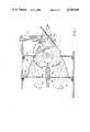
- FIG. 1is a schematic longitudinal sectional view through a preferred form of reflector system in accordance with this invention
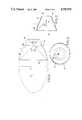
- FIG. 2is a longitudinal sectional view, on a reduced sale, of the reflector by itself;
- FIG. 3is an end elevation view of the reflector of FIG. 2 as seen from the left end thereof;
- FIG. 4is an enlarged schematic illustration showing in greater detail the geometry of the reflector.
- FIG. 5is a schematic longitudinal section similar to FIG. 1 but showing a modified form of reflector system in accordance with this invention.
- FIG. 1there is shown a preferred form of reflector system 1 in accordance with this invention including a reflector 2 for collecting light rays emitted from a light source L mounted within the reflector and focusing such light rays on a relatively tight target or light receiving area A outside the reflector.
- Suitable mounting brackets 4,5may be provided for mounting the reflector 2 within a box or housing 6 as schematically illustrated.
- Reflector 2is a hybrid reflector which combines both ellipsoidal and hemispherical shapes as described hereafter, and may be constructed from any suitable material such as aluminum, glass or nickel coated with an acceptable reflective coating such as enhanced (dielectric) aluminum or overcoated silver.
- a suitable reflective coating for the glassmay be a dichroic thin film to aid in heat removal from the system.
- the reflectorincludes an ellipsoidal portion 7 to take advantage of the inherent geometrical properties of ellipsoidal shapes which are ideal for focusing light into a small opening or target.
- any point light source placed at one of the foci of an ellipsewill emit light rays that will always converge on the other focus.
- there is no true point source light emitterand the further one deviates from a point light source in a true elliptical or ellipsoidal reflector, the worse the defocus becomes.
- the purpose of the hemispherical portion 10 of the reflector 2is to take the light rays R 1 emanating from the light source L placed in the region of the first focus P that would otherwise have impinged on the rear portion of a conventional ellipsoidal reflector and lost to defocus and redirect them back through the light source so that these reflected light rays R 3 also eventually strike the ellipsoidal portion 7 forwardly of the first focus.
- substantially half of the 90° emitted arc from a lamp L placed substantially at the first focus P which impinges on the hemispherical portion 10will be reflected back through the lamp untileventually substantially all of the rays R 1 , R 2 leaving the lamp will strike the ellipsoidal portion 7 forwardly of the first focus P.
- the reflector system 1was designed to channel light into a relatively tight target or light receiving area A at the final focus F such as the end 12 of a fiber optics cable C having a diameter, for example, of 1.5 inches. Not only does this require the tailoring of the final focus F as close to the cable diameter as possible, but also requires that the light be focused on the fiber optics ends at angles within the limited acceptance angle for the particular optical fibers being used, such as a 60° solid angle cone.
- the final focus Fis desirable located outside the reflector 2, and the hemispherical portion 10 is sized so that the edge 15 of the small opening or mouth 16 at the rearmost end of the hemispherical portion 10 does not block a significant amount of radiation being reflected by the ellipsoidal portion 7 and still bounces the initial ray R 1 emitted from the lamp L back onto the ellipsoidal portion as reflected rays R 3 as schematically shown in FIG. 1.
- Another important aspect of the reflector system 1 of the present inventionis the manner in which the light is reflected back through the small opening or mouth 16 at the rearmost end of the hemispherical portion 10 of the reflector.
- the light rays emanating from a light source at a first focusare collected at a second focus within the reflector itself.
- a major objection to thisis that the overall lighting system must be of an elongated construction which in many cases does not provide an acceptable package shape.
- the reflector system 1is made much more compact by shortening up its length and placing a mirror 20 at a large opening 21 where the ellipsoidal portion 7 of the reflector terminates forwardly of the first focus P for redirecting the light rays R 2 , R 3 impinging on the ellipsoidal portion 7 back through the small opening or mouth 16 at the rearmost end of the hemispherical portion 10.
- mirror 20can be a conventional silver coated mirror which will redirect all of the light rays back through the mouth 16 of the reflector.
- mirror 20is preferably a dichroic mirror of known type having suitable multi-layered coatings thereon similar to that used in the General Electric Company's Quartz Line reflector lamps to allow certain bandwidths of energy to pass through the mirror and cause reflection of others.
- the first 85% to 90% of the initially emitted infra-red radiation R 4can be eliminated so that substantially only the optical wavelengths R 5 of the radiation incident upon the mirror are redirected back through the mouth of the reflector.
- the actual placement or location of the mirror 20is important in order to assure that the maximum amount of light rays emitted from the light source L will follow the classical elliptical path and be directed back through the open mouth 16 of the reflector. To that end, it has been found that the mirror 20 should be placed no closer to the light source L than the point 22 at which a 45° ray emanating from a point light source at the first focal point P meets the internal surface of the elliptical portion 7 of the reflector as schematically shown in FIGS. 2 and 4. At the same time, the mirror 20 should not be moved much further away from the light source L or the final focus F will move back into the mouth 16 of the reflector. Any movement of the mirror 20 further away from the light source (at the first focus P) will cause the final focus F to move twice that amount toward the mouth 16 of the reflector.
- mirror 23may be mounted adjacent the reflector mouth oriented at an angle of approximately 45° to the normal of the reflector mouth for redirecting the light rays passing through the reflector mouth onto the end 12 of a fiber optics cable C whose axis is normal to the mouth (reflector) axis as schematically shown in FIG. 1.
- mirror 23may be a dichroic mirror similar to the mirror 20 previously described for eliminating additional infra-red radiation R 6 emitted from the light source. This mirror 23 coupled with mirror 20 will remove substantially all non-optical energy rays R 4 , R 6 emitted by the light source.
- mirror 23may be eliminated and the end 12 of the optical light cable C or other light receiving area A may be placed at a final focus F' exteriorly of the mouth 16 of the reflector 2 in coaxial alignment with the reflector as shown in FIG. 5. Otherwise, the details of construction and operation of the reflector system shown in FIG. 5 are identical to that shown in the FIG. 1 embodiment. Accordingly, the same reference numerals are used to identify like parts.
- the ellipsoidal portion 7 of the reflector 2commences at the intersection of a plane passing through the first focus P normal to the major axis X and extends forwardly therefrom in the direction of the major axis toward the minor axis Y.
- the hemispherical portion 10 of the reflectoralso commences at the same place as the ellipsoidal portion 7.
- the hemispherical portion 10has a center axis substantially coincident with the first focus P of the ellipsoidal portion 7.
- the hemispherical portion 10extends rearwardly in the opposite direction from the ellipsoidal portion 7.
- each of the ellipsoidal and hemispherical portions 7, 10extend (in opposite directions) over a distance of approximately 45° as measured from the first focus P. Moreover, it has been found that in order to maintain the resulting incident angles of acceptance of the light at the final focus F within a 60° solid angle cone, the eccentricity of the ellipsoidal portion of the reflector must fall between approximately 0.8 and 1.0. For best results, when the reflector is viewed in a two-dimensional longitudinal section as shown in FIGS.
- the mouth opening edge 15, the point 24 where the ellipsoidal and hemispherical portions 7, 10 meet, the large opening edge 22 and the edge 25 of the target Aall desirably fall substantially in a straight line 26, shown in phantom lines in FIGS. 1 and 5.
- the ellipsoidal portion 7 of the reflector 2has a semi-major axis X of approximately 10.88 inches and a semi-minor axis Y of approximately 6.087 inches and an eccentricity of approximately 0.829. Also, both the ellipsoidal focus and hemispherical center intersect at the first focus P as aforesaid, and the ellipsoidal and hemispherical portions 7,10 extend over an arc distance of approximately 45° as measured from such first focus.
- the reflector systems of the present inventionprovide for the relatively efficient collection and focalization of light rays upon a relatively tight target or light receiving area preferably with minimum loss of optical energy and maximum removal of infra-red energy from a light source. While such reflector systems are primarily intended for fiber optical applications, it will be apparent that such systems can also be utilized for other illumination applications as well. With such systems, it is estimated that approximately 35% optical efficiency and approximately 99% non-optical efficiency can be obtained.
Landscapes
- Physics & Mathematics (AREA)
- Engineering & Computer Science (AREA)
- General Engineering & Computer Science (AREA)
- General Physics & Mathematics (AREA)
- Optics & Photonics (AREA)
- Optical Elements Other Than Lenses (AREA)
- Non-Portable Lighting Devices Or Systems Thereof (AREA)
Abstract
Description
Claims (26)
Priority Applications (3)
| Application Number | Priority Date | Filing Date | Title |
|---|---|---|---|
| US07/034,840US4755918A (en) | 1987-04-06 | 1987-04-06 | Reflector system |
| EP88302958AEP0286333A3 (en) | 1987-04-06 | 1988-03-31 | Reflector system |
| JP63083215AJPS63314703A (en) | 1987-04-06 | 1988-04-06 | Reflector |
Applications Claiming Priority (1)
| Application Number | Priority Date | Filing Date | Title |
|---|---|---|---|
| US07/034,840US4755918A (en) | 1987-04-06 | 1987-04-06 | Reflector system |
Publications (1)
| Publication Number | Publication Date |
|---|---|
| US4755918Atrue US4755918A (en) | 1988-07-05 |
Family
ID=21878935
Family Applications (1)
| Application Number | Title | Priority Date | Filing Date |
|---|---|---|---|
| US07/034,840Expired - LifetimeUS4755918A (en) | 1987-04-06 | 1987-04-06 | Reflector system |
Country Status (3)
| Country | Link |
|---|---|
| US (1) | US4755918A (en) |
| EP (1) | EP0286333A3 (en) |
| JP (1) | JPS63314703A (en) |
Cited By (52)
| Publication number | Priority date | Publication date | Assignee | Title |
|---|---|---|---|---|
| US4897771A (en)* | 1987-11-24 | 1990-01-30 | Lumitex, Inc. | Reflector and light system |
| US5315490A (en)* | 1989-10-13 | 1994-05-24 | Bastable Rodney C | Light fittings |
| US5317484A (en)* | 1993-02-01 | 1994-05-31 | General Electric Company | Collection optics for high brightness discharge light source |
| US5365412A (en)* | 1993-01-07 | 1994-11-15 | Ford Motor Company | Low profile illuminator |
| US5390265A (en)* | 1993-12-17 | 1995-02-14 | General Motors Corporation | Fiber optic light coupler |
| US5406462A (en)* | 1992-12-28 | 1995-04-11 | Ford Motor Company | Apparatus for collecting and transmitting light |
| US5416669A (en)* | 1992-01-20 | 1995-05-16 | Nippondenso Co., Ltd. | Light source apparatus |
| US5428365A (en)* | 1994-03-25 | 1995-06-27 | Inwave Corporation | Method and apparatus for generating uniform illumination |
| US5434754A (en)* | 1993-12-27 | 1995-07-18 | Ford Motor Company | Light manifold |
| US5471371A (en)* | 1993-01-08 | 1995-11-28 | Ford Motor Company | High efficiency illuminator |
| US5479322A (en)* | 1993-07-16 | 1995-12-26 | Fiberstars, Inc. | Lighting system and method for fiber optic and area illumination |
| US5515242A (en)* | 1994-10-03 | 1996-05-07 | Ford Motor Company | Double confocal fiber optic light collector |
| WO1997001411A1 (en)* | 1995-06-28 | 1997-01-16 | Nauchno-Proizvodstvennaya Firma 'mgm' | Device for soldering articles using a light beam |
| US5971569A (en)* | 1997-06-11 | 1999-10-26 | Steris Corporation | Surgical light with stacked elliptical reflector |
| US6086234A (en)* | 1997-01-31 | 2000-07-11 | Remote Source Lighting International, Inc. | Parabolic and spherical multiport illuminators for light guides |
| WO2000053972A1 (en)* | 1999-03-08 | 2000-09-14 | Minnesota Mining And Manufacturing Company | High efficiency reflector for directing collimated light into light guides |
| US6168302B1 (en) | 1997-12-09 | 2001-01-02 | Cooper Automotive Products, Inc. | Hybrid distributed lighting system for a vehicle |
| US6186650B1 (en) | 1997-12-09 | 2001-02-13 | Cooper Automotive Products, Inc. | Vehicle headlamp with beamforming waveguide |
| US6193399B1 (en) | 1997-12-09 | 2001-02-27 | Cooper Automotive Products, Inc. | Optical waveguide structures for vehicle lighting |
| US6200005B1 (en) | 1998-12-01 | 2001-03-13 | Ilc Technology, Inc. | Xenon ceramic lamp with integrated compound reflectors |
| US6220740B1 (en)* | 1993-10-20 | 2001-04-24 | General Electric Company | High efficiency dual output light source |
| US6227682B1 (en) | 2000-03-22 | 2001-05-08 | Cogent Light Technologies, Inc. | Coupling of light from a small light source for projection systems using parabolic reflectors |
| US6238074B1 (en) | 1997-12-09 | 2001-05-29 | Cooper Automotive Products, Inc. | Optical waveguide structures |
| US6418253B2 (en) | 1999-03-08 | 2002-07-09 | Minnesota Mining And Manufacturing Company | High efficiency reflector for directing collimated light into light guides |
| US20020122621A1 (en)* | 2001-03-02 | 2002-09-05 | Li Kenneth K. | Coupling of light from a non-circular light source |
| US6488395B2 (en) | 1998-01-30 | 2002-12-03 | Federal-Mogul World Wide, Inc. | Low profile lighting |
| US6563255B1 (en) | 2000-10-19 | 2003-05-13 | General Electric Company | Luminaire incorporating arc tube preheater |
| US20030128341A1 (en)* | 2001-08-23 | 2003-07-10 | Li Kenneth K. | Led illumination engine using a reflector |
| US6739726B2 (en) | 2001-02-05 | 2004-05-25 | Wavien, Inc. | Illumination engine for a projection display using a tapered light pipe |
| US20040149998A1 (en)* | 2002-12-02 | 2004-08-05 | Henson Gordon D. | Illumination system using a plurality of light sources |
| US20050041430A1 (en)* | 2003-08-21 | 2005-02-24 | Wimberly Randal Lee | Heat distributing hybrid reflector lamp or illumination system |
| US20050117366A1 (en)* | 2003-12-02 | 2005-06-02 | Simbal John J. | Reflective light coupler |
| US20050116235A1 (en)* | 2003-12-02 | 2005-06-02 | Schultz John C. | Illumination assembly |
| US20050116635A1 (en)* | 2003-12-02 | 2005-06-02 | Walson James E. | Multiple LED source and method for assembling same |
| US20050140270A1 (en)* | 2003-12-02 | 2005-06-30 | Henson Gordon D. | Solid state light device |
| US20080043470A1 (en)* | 2006-08-17 | 2008-02-21 | Randal Lee Wimberly | Reflector lamp or illumination system |
| US7456805B2 (en) | 2003-12-18 | 2008-11-25 | 3M Innovative Properties Company | Display including a solid state light device and method using same |
| CN100494772C (en)* | 2004-12-13 | 2009-06-03 | 斯坦雷电气株式会社 | Vehicle Lamps |
| EP1266173B1 (en)* | 2000-03-21 | 2009-08-19 | Wavien, Inc. | Optical systems having retro-reflectors |
| US9565782B2 (en) | 2013-02-15 | 2017-02-07 | Ecosense Lighting Inc. | Field replaceable power supply cartridge |
| US9568665B2 (en) | 2015-03-03 | 2017-02-14 | Ecosense Lighting Inc. | Lighting systems including lens modules for selectable light distribution |
| USD782094S1 (en) | 2015-07-20 | 2017-03-21 | Ecosense Lighting Inc. | LED luminaire having a mounting system |
| USD782093S1 (en) | 2015-07-20 | 2017-03-21 | Ecosense Lighting Inc. | LED luminaire having a mounting system |
| USD785218S1 (en) | 2015-07-06 | 2017-04-25 | Ecosense Lighting Inc. | LED luminaire having a mounting system |
| US9651227B2 (en) | 2015-03-03 | 2017-05-16 | Ecosense Lighting Inc. | Low-profile lighting system having pivotable lighting enclosure |
| US9651232B1 (en) | 2015-08-03 | 2017-05-16 | Ecosense Lighting Inc. | Lighting system having a mounting device |
| US9651216B2 (en) | 2015-03-03 | 2017-05-16 | Ecosense Lighting Inc. | Lighting systems including asymmetric lens modules for selectable light distribution |
| US9746159B1 (en) | 2015-03-03 | 2017-08-29 | Ecosense Lighting Inc. | Lighting system having a sealing system |
| US9869450B2 (en) | 2015-02-09 | 2018-01-16 | Ecosense Lighting Inc. | Lighting systems having a truncated parabolic- or hyperbolic-conical light reflector, or a total internal reflection lens; and having another light reflector |
| US10477636B1 (en) | 2014-10-28 | 2019-11-12 | Ecosense Lighting Inc. | Lighting systems having multiple light sources |
| US10801696B2 (en) | 2015-02-09 | 2020-10-13 | Ecosense Lighting Inc. | Lighting systems generating partially-collimated light emissions |
| US11306897B2 (en) | 2015-02-09 | 2022-04-19 | Ecosense Lighting Inc. | Lighting systems generating partially-collimated light emissions |
Families Citing this family (5)
| Publication number | Priority date | Publication date | Assignee | Title |
|---|---|---|---|---|
| DE4205069A1 (en)* | 1992-02-19 | 1993-08-26 | Swarovski & Co | REFLECTOR SYSTEM FOR A LIGHTING BODY |
| RU2047875C1 (en)* | 1993-03-30 | 1995-11-10 | Научно-производственная фирма "МГМ" | Device for light-beam treatment |
| US5625738A (en)* | 1994-06-28 | 1997-04-29 | Corning Incorporated | Apparatus for uniformly illuminating a light valve |
| DE102005032934A1 (en)* | 2005-07-12 | 2007-01-25 | Philipps-Universität Marburg | Invention concerning reflector systems |
| JP6229321B2 (en)* | 2013-06-07 | 2017-11-15 | 岩崎電気株式会社 | Light source device |
Citations (13)
| Publication number | Priority date | Publication date | Assignee | Title |
|---|---|---|---|---|
| GB119470A (en)* | 1917-09-21 | 1919-10-24 | Henry Riegel Evans | Improvements relating to Lamps for Lighting. |
| US1575327A (en)* | 1924-05-02 | 1926-03-02 | Garford Francis Sydney | Headlight |
| US1995012A (en)* | 1932-05-13 | 1935-03-19 | Rivier Louis | Lighting device |
| GB763376A (en)* | 1954-05-11 | 1956-12-12 | Reinhard Paul Henry Hinds | Improvements relating to vehicle lamps |
| US3267274A (en)* | 1963-05-08 | 1966-08-16 | Mole Richardson England Ltd | Television and film studio lamp |
| US3770338A (en)* | 1971-08-19 | 1973-11-06 | Chadwick Elect Inc H | Fiber optics light source |
| US4241382A (en)* | 1979-03-23 | 1980-12-23 | Maurice Daniel | Fiber optics illuminator |
| US4305099A (en)* | 1980-02-01 | 1981-12-08 | General Electric Company | Light collection system |
| US4443834A (en)* | 1981-04-07 | 1984-04-17 | Westalische Metall Industrie Kg Hueck & Co. | Interior lighting for vehicles with rotatable mask |
| US4447865A (en)* | 1982-05-13 | 1984-05-08 | General Electric Company | Reflector lamp |
| US4494176A (en)* | 1984-03-14 | 1985-01-15 | General Electric Company | Lamps having multiple and aimed parabolic sections for increased useful light output |
| US4536834A (en)* | 1984-05-22 | 1985-08-20 | General Electric Company | R lamp having an improved neck section for increasing the useful light output |
| US4654758A (en)* | 1984-09-21 | 1987-03-31 | Tungsram Rt. | Headlamp |
Family Cites Families (4)
| Publication number | Priority date | Publication date | Assignee | Title |
|---|---|---|---|---|
| BE467046A (en)* | ||||
| FR670082A (en)* | 1928-06-15 | 1929-11-25 | Non-glare headlight for road vehicles | |
| FR2090026A1 (en)* | 1970-04-16 | 1972-01-14 | African Explosives & Chem | OPTICAL CAPACITOR FOR LIGHT SOURCE |
| SE364179B (en)* | 1972-11-17 | 1974-02-18 | Projektutveckling Ab |
- 1987
- 1987-04-06USUS07/034,840patent/US4755918A/ennot_activeExpired - Lifetime
- 1988
- 1988-03-31EPEP88302958Apatent/EP0286333A3/ennot_activeWithdrawn
- 1988-04-06JPJP63083215Apatent/JPS63314703A/enactivePending
Patent Citations (13)
| Publication number | Priority date | Publication date | Assignee | Title |
|---|---|---|---|---|
| GB119470A (en)* | 1917-09-21 | 1919-10-24 | Henry Riegel Evans | Improvements relating to Lamps for Lighting. |
| US1575327A (en)* | 1924-05-02 | 1926-03-02 | Garford Francis Sydney | Headlight |
| US1995012A (en)* | 1932-05-13 | 1935-03-19 | Rivier Louis | Lighting device |
| GB763376A (en)* | 1954-05-11 | 1956-12-12 | Reinhard Paul Henry Hinds | Improvements relating to vehicle lamps |
| US3267274A (en)* | 1963-05-08 | 1966-08-16 | Mole Richardson England Ltd | Television and film studio lamp |
| US3770338A (en)* | 1971-08-19 | 1973-11-06 | Chadwick Elect Inc H | Fiber optics light source |
| US4241382A (en)* | 1979-03-23 | 1980-12-23 | Maurice Daniel | Fiber optics illuminator |
| US4305099A (en)* | 1980-02-01 | 1981-12-08 | General Electric Company | Light collection system |
| US4443834A (en)* | 1981-04-07 | 1984-04-17 | Westalische Metall Industrie Kg Hueck & Co. | Interior lighting for vehicles with rotatable mask |
| US4447865A (en)* | 1982-05-13 | 1984-05-08 | General Electric Company | Reflector lamp |
| US4494176A (en)* | 1984-03-14 | 1985-01-15 | General Electric Company | Lamps having multiple and aimed parabolic sections for increased useful light output |
| US4536834A (en)* | 1984-05-22 | 1985-08-20 | General Electric Company | R lamp having an improved neck section for increasing the useful light output |
| US4654758A (en)* | 1984-09-21 | 1987-03-31 | Tungsram Rt. | Headlamp |
Cited By (63)
| Publication number | Priority date | Publication date | Assignee | Title |
|---|---|---|---|---|
| US4897771A (en)* | 1987-11-24 | 1990-01-30 | Lumitex, Inc. | Reflector and light system |
| US5315490A (en)* | 1989-10-13 | 1994-05-24 | Bastable Rodney C | Light fittings |
| US5416669A (en)* | 1992-01-20 | 1995-05-16 | Nippondenso Co., Ltd. | Light source apparatus |
| US5406462A (en)* | 1992-12-28 | 1995-04-11 | Ford Motor Company | Apparatus for collecting and transmitting light |
| US5365412A (en)* | 1993-01-07 | 1994-11-15 | Ford Motor Company | Low profile illuminator |
| US5471371A (en)* | 1993-01-08 | 1995-11-28 | Ford Motor Company | High efficiency illuminator |
| US5317484A (en)* | 1993-02-01 | 1994-05-31 | General Electric Company | Collection optics for high brightness discharge light source |
| US5479322A (en)* | 1993-07-16 | 1995-12-26 | Fiberstars, Inc. | Lighting system and method for fiber optic and area illumination |
| US6220740B1 (en)* | 1993-10-20 | 2001-04-24 | General Electric Company | High efficiency dual output light source |
| US5390265A (en)* | 1993-12-17 | 1995-02-14 | General Motors Corporation | Fiber optic light coupler |
| US5434754A (en)* | 1993-12-27 | 1995-07-18 | Ford Motor Company | Light manifold |
| US5428365A (en)* | 1994-03-25 | 1995-06-27 | Inwave Corporation | Method and apparatus for generating uniform illumination |
| US5515242A (en)* | 1994-10-03 | 1996-05-07 | Ford Motor Company | Double confocal fiber optic light collector |
| WO1997001411A1 (en)* | 1995-06-28 | 1997-01-16 | Nauchno-Proizvodstvennaya Firma 'mgm' | Device for soldering articles using a light beam |
| US6086234A (en)* | 1997-01-31 | 2000-07-11 | Remote Source Lighting International, Inc. | Parabolic and spherical multiport illuminators for light guides |
| US5971569A (en)* | 1997-06-11 | 1999-10-26 | Steris Corporation | Surgical light with stacked elliptical reflector |
| US6168302B1 (en) | 1997-12-09 | 2001-01-02 | Cooper Automotive Products, Inc. | Hybrid distributed lighting system for a vehicle |
| US6238074B1 (en) | 1997-12-09 | 2001-05-29 | Cooper Automotive Products, Inc. | Optical waveguide structures |
| US6193399B1 (en) | 1997-12-09 | 2001-02-27 | Cooper Automotive Products, Inc. | Optical waveguide structures for vehicle lighting |
| US6186650B1 (en) | 1997-12-09 | 2001-02-13 | Cooper Automotive Products, Inc. | Vehicle headlamp with beamforming waveguide |
| US6260991B1 (en) | 1997-12-09 | 2001-07-17 | Cooper Automotive Products, Inc. | Compact illuminator for distributed lighting system |
| US6488395B2 (en) | 1998-01-30 | 2002-12-03 | Federal-Mogul World Wide, Inc. | Low profile lighting |
| US6200005B1 (en) | 1998-12-01 | 2001-03-13 | Ilc Technology, Inc. | Xenon ceramic lamp with integrated compound reflectors |
| US6418253B2 (en) | 1999-03-08 | 2002-07-09 | Minnesota Mining And Manufacturing Company | High efficiency reflector for directing collimated light into light guides |
| US6522807B2 (en) | 1999-03-08 | 2003-02-18 | 3M Innovative Properties Company | High efficiency reflector for directing collimated light into light guides |
| WO2000053972A1 (en)* | 1999-03-08 | 2000-09-14 | Minnesota Mining And Manufacturing Company | High efficiency reflector for directing collimated light into light guides |
| EP1266173B1 (en)* | 2000-03-21 | 2009-08-19 | Wavien, Inc. | Optical systems having retro-reflectors |
| US6227682B1 (en) | 2000-03-22 | 2001-05-08 | Cogent Light Technologies, Inc. | Coupling of light from a small light source for projection systems using parabolic reflectors |
| US6563255B1 (en) | 2000-10-19 | 2003-05-13 | General Electric Company | Luminaire incorporating arc tube preheater |
| US6739726B2 (en) | 2001-02-05 | 2004-05-25 | Wavien, Inc. | Illumination engine for a projection display using a tapered light pipe |
| US6856727B2 (en) | 2001-03-02 | 2005-02-15 | Wavien, Inc. | Coupling of light from a non-circular light source |
| US20020122621A1 (en)* | 2001-03-02 | 2002-09-05 | Li Kenneth K. | Coupling of light from a non-circular light source |
| US20030128341A1 (en)* | 2001-08-23 | 2003-07-10 | Li Kenneth K. | Led illumination engine using a reflector |
| US6926435B2 (en) | 2001-08-23 | 2005-08-09 | Wavien, Inc. | Led illumination engine using a reflector |
| US20040149998A1 (en)* | 2002-12-02 | 2004-08-05 | Henson Gordon D. | Illumination system using a plurality of light sources |
| US7658526B2 (en) | 2002-12-02 | 2010-02-09 | 3M Innovative Properties Company | Illumination system using a plurality of light sources |
| US7360924B2 (en) | 2002-12-02 | 2008-04-22 | 3M Innovative Properties Company | Illumination system using a plurality of light sources |
| US20070103925A1 (en)* | 2002-12-02 | 2007-05-10 | 3M Innovative Properties Company | Illumination system using a plurality of light sources |
| US7131749B2 (en)* | 2003-08-21 | 2006-11-07 | Randal Lee Wimberly | Heat distributing hybrid reflector lamp or illumination system |
| US20050041430A1 (en)* | 2003-08-21 | 2005-02-24 | Wimberly Randal Lee | Heat distributing hybrid reflector lamp or illumination system |
| US20050116235A1 (en)* | 2003-12-02 | 2005-06-02 | Schultz John C. | Illumination assembly |
| US20050140270A1 (en)* | 2003-12-02 | 2005-06-30 | Henson Gordon D. | Solid state light device |
| US7329887B2 (en) | 2003-12-02 | 2008-02-12 | 3M Innovative Properties Company | Solid state light device |
| US20050117366A1 (en)* | 2003-12-02 | 2005-06-02 | Simbal John J. | Reflective light coupler |
| US20050116635A1 (en)* | 2003-12-02 | 2005-06-02 | Walson James E. | Multiple LED source and method for assembling same |
| US7403680B2 (en)* | 2003-12-02 | 2008-07-22 | 3M Innovative Properties Company | Reflective light coupler |
| US7456805B2 (en) | 2003-12-18 | 2008-11-25 | 3M Innovative Properties Company | Display including a solid state light device and method using same |
| CN100494772C (en)* | 2004-12-13 | 2009-06-03 | 斯坦雷电气株式会社 | Vehicle Lamps |
| US20080043470A1 (en)* | 2006-08-17 | 2008-02-21 | Randal Lee Wimberly | Reflector lamp or illumination system |
| US9565782B2 (en) | 2013-02-15 | 2017-02-07 | Ecosense Lighting Inc. | Field replaceable power supply cartridge |
| US10477636B1 (en) | 2014-10-28 | 2019-11-12 | Ecosense Lighting Inc. | Lighting systems having multiple light sources |
| US11614217B2 (en) | 2015-02-09 | 2023-03-28 | Korrus, Inc. | Lighting systems generating partially-collimated light emissions |
| US9869450B2 (en) | 2015-02-09 | 2018-01-16 | Ecosense Lighting Inc. | Lighting systems having a truncated parabolic- or hyperbolic-conical light reflector, or a total internal reflection lens; and having another light reflector |
| US11306897B2 (en) | 2015-02-09 | 2022-04-19 | Ecosense Lighting Inc. | Lighting systems generating partially-collimated light emissions |
| US10801696B2 (en) | 2015-02-09 | 2020-10-13 | Ecosense Lighting Inc. | Lighting systems generating partially-collimated light emissions |
| US9651216B2 (en) | 2015-03-03 | 2017-05-16 | Ecosense Lighting Inc. | Lighting systems including asymmetric lens modules for selectable light distribution |
| US9568665B2 (en) | 2015-03-03 | 2017-02-14 | Ecosense Lighting Inc. | Lighting systems including lens modules for selectable light distribution |
| US9746159B1 (en) | 2015-03-03 | 2017-08-29 | Ecosense Lighting Inc. | Lighting system having a sealing system |
| US9651227B2 (en) | 2015-03-03 | 2017-05-16 | Ecosense Lighting Inc. | Low-profile lighting system having pivotable lighting enclosure |
| USD785218S1 (en) | 2015-07-06 | 2017-04-25 | Ecosense Lighting Inc. | LED luminaire having a mounting system |
| USD782093S1 (en) | 2015-07-20 | 2017-03-21 | Ecosense Lighting Inc. | LED luminaire having a mounting system |
| USD782094S1 (en) | 2015-07-20 | 2017-03-21 | Ecosense Lighting Inc. | LED luminaire having a mounting system |
| US9651232B1 (en) | 2015-08-03 | 2017-05-16 | Ecosense Lighting Inc. | Lighting system having a mounting device |
Also Published As
| Publication number | Publication date |
|---|---|
| EP0286333A2 (en) | 1988-10-12 |
| JPS63314703A (en) | 1988-12-22 |
| EP0286333A3 (en) | 1989-11-02 |
Similar Documents
| Publication | Publication Date | Title |
|---|---|---|
| US4755918A (en) | Reflector system | |
| US4897771A (en) | Reflector and light system | |
| US5103381A (en) | Lamp reflector system | |
| US7618158B2 (en) | Illumination system using filament lamps | |
| US6123436A (en) | Optical device for modifying the angular and spatial distribution of illuminating energy | |
| US5406462A (en) | Apparatus for collecting and transmitting light | |
| CN1228566C (en) | Collecting and converging optics utilizing cascaded parabolic mirrors | |
| US20060061894A1 (en) | Coupling of light from a light source to a target using dual ellipsoidal reflectors | |
| EP2409184B1 (en) | High efficiency optical coupler | |
| US6619820B2 (en) | Light condensing and collecting systems using lensed light pipes | |
| KR101324807B1 (en) | Dual paraboloid reflector and dual ellipsoid reflector systems with optimized magnification | |
| US7513630B2 (en) | Compact dual ellipsoidal reflector (DER) system having two molded ellipsoidal modules such that a radiation receiving module reflects a portion of rays to an opening in the other module | |
| US7631989B2 (en) | Dual paraboloid reflector and dual ellipsoid reflector systems with optimized magnification | |
| US20060018125A1 (en) | High-efficiency fiber optic lighting system | |
| CN1355893A (en) | Improved coupling of light from small arc lamp to larger target | |
| GB2201527A (en) | - Fibre optic coupling device | |
| JPH112726A (en) | Light guide device, light condensing device and illumination system | |
| CA2377497A1 (en) | System for collecting and condensing light | |
| TW200419103A (en) | Multiple output illumination using reflectors | |
| CA2608368A1 (en) | Dual paraboloid reflector and dual ellipsoid reflector systems with optimized magnification | |
| TW455697B (en) | System for collecting and condensing light | |
| NL8101884A (en) | ELECTRICAL REFLECTOR LAMP. | |
| JPH0433248A (en) | Electric bulb with reflecting mirror |
Legal Events
| Date | Code | Title | Description |
|---|---|---|---|
| AS | Assignment | Owner name:LUMITEX, INC., 11941 ABBEY ROAD, UNIT H, NORTH ROY Free format text:ASSIGNMENT OF ASSIGNORS INTEREST.;ASSIGNORS:BODNAR, TIMOTHY J.;PRISTASH, DAVID J.;REEL/FRAME:004695/0313 Effective date:19870401 | |
| STCF | Information on status: patent grant | Free format text:PATENTED CASE | |
| FEPP | Fee payment procedure | Free format text:PAYOR NUMBER ASSIGNED (ORIGINAL EVENT CODE: ASPN); ENTITY STATUS OF PATENT OWNER: LARGE ENTITY | |
| AS | Assignment | Owner name:AMERITRUST COMPANY NATIONAL ASSOCIATION, A NATIONA Free format text:SECURITY INTEREST;ASSIGNOR:LUMITEX, INC.;REEL/FRAME:005736/0164 Effective date:19910329 | |
| FPAY | Fee payment | Year of fee payment:4 | |
| FEPP | Fee payment procedure | Free format text:PAT HLDR NO LONGER CLAIMS SMALL ENT STAT AS SMALL BUSINESS (ORIGINAL EVENT CODE: LSM2); ENTITY STATUS OF PATENT OWNER: LARGE ENTITY | |
| FPAY | Fee payment | Year of fee payment:8 | |
| AS | Assignment | Owner name:KEYBANK NATIONAL ASSOCIATION, OHIO Free format text:SECURITY AGREEMENT;ASSIGNOR:LUMITEX, INC., A CORPORATION OF OHIO;REEL/FRAME:010144/0284 Effective date:19990108 | |
| FPAY | Fee payment | Year of fee payment:12 | |
| AS | Assignment | Owner name:LUMITEX, INC., OHIO Free format text:RELEASE OF SECURITY AGREEMENT;ASSIGNOR:OHIO MEZZANINE FUND, LTD.;REEL/FRAME:011485/0890 Effective date:20000927 |