US4755169A - Automatic medicament ingredient mixing and injecting apparatus - Google Patents
Automatic medicament ingredient mixing and injecting apparatusDownload PDFInfo
- Publication number
- US4755169A US4755169AUS06/943,135US94313586AUS4755169AUS 4755169 AUS4755169 AUS 4755169AUS 94313586 AUS94313586 AUS 94313586AUS 4755169 AUS4755169 AUS 4755169A
- Authority
- US
- United States
- Prior art keywords
- plunger
- container
- movement
- medicament
- piston
- Prior art date
- Legal status (The legal status is an assumption and is not a legal conclusion. Google has not performed a legal analysis and makes no representation as to the accuracy of the status listed.)
- Expired - Lifetime
Links
- 239000003814drugSubstances0.000titleclaimsabstractdescription124
- 239000004615ingredientSubstances0.000titleclaimsabstractdescription80
- 239000007788liquidSubstances0.000claimsabstractdescription92
- 238000000034methodMethods0.000claimsabstractdescription40
- 210000003205muscleAnatomy0.000claimsabstractdescription30
- 230000000694effectsEffects0.000claimsabstractdescription24
- 230000004044responseEffects0.000claimsabstractdescription18
- 230000000712assemblyEffects0.000claimsdescription18
- 238000000429assemblyMethods0.000claimsdescription18
- 239000000843powderSubstances0.000claimsdescription16
- 239000003085diluting agentSubstances0.000claims6
- 210000003811fingerAnatomy0.000description36
- 238000002347injectionMethods0.000description11
- 239000007924injectionSubstances0.000description11
- 230000002093peripheral effectEffects0.000description8
- 239000012858resilient materialSubstances0.000description7
- 238000004891communicationMethods0.000description5
- 230000006835compressionEffects0.000description5
- 238000007906compressionMethods0.000description5
- 230000009977dual effectEffects0.000description5
- 230000000717retained effectEffects0.000description4
- 230000009471actionEffects0.000description3
- 210000000689upper legAnatomy0.000description3
- 239000000729antidoteSubstances0.000description2
- 238000001802infusionMethods0.000description2
- 239000002991molded plasticSubstances0.000description2
- 238000009877renderingMethods0.000description2
- 238000007789sealingMethods0.000description2
- 125000006850spacer groupChemical group0.000description2
- 206010003402Arthropod stingDiseases0.000description1
- NNJVILVZKWQKPM-UHFFFAOYSA-NLidocaineChemical compoundCCN(CC)CC(=O)NC1=C(C)C=CC=C1CNNJVILVZKWQKPM-UHFFFAOYSA-N0.000description1
- 238000010521absorption reactionMethods0.000description1
- 230000003288anthiarrhythmic effectEffects0.000description1
- 239000003416antiarrhythmic agentSubstances0.000description1
- 229940075522antidotesDrugs0.000description1
- 239000008280bloodSubstances0.000description1
- 210000004369bloodAnatomy0.000description1
- 230000008859changeEffects0.000description1
- 238000010276constructionMethods0.000description1
- 238000007599dischargingMethods0.000description1
- 239000011521glassSubstances0.000description1
- 230000036512infertilityEffects0.000description1
- 238000010255intramuscular injectionMethods0.000description1
- 239000007927intramuscular injectionSubstances0.000description1
- 229960004194lidocaineDrugs0.000description1
- 238000012423maintenanceMethods0.000description1
- 239000000463materialSubstances0.000description1
- 230000007246mechanismEffects0.000description1
- 239000002184metalSubstances0.000description1
- 239000000203mixtureSubstances0.000description1
- 238000012986modificationMethods0.000description1
- 230000004048modificationEffects0.000description1
- 238000004806packaging method and processMethods0.000description1
- 239000004033plasticSubstances0.000description1
- 230000008569processEffects0.000description1
- 239000011347resinSubstances0.000description1
- 229920005989resinPolymers0.000description1
- 239000000126substanceSubstances0.000description1
- 230000001225therapeutic effectEffects0.000description1
- 210000003813thumbAnatomy0.000description1
- 238000013022ventingMethods0.000description1
Images


Classifications
- A—HUMAN NECESSITIES
- A61—MEDICAL OR VETERINARY SCIENCE; HYGIENE
- A61M—DEVICES FOR INTRODUCING MEDIA INTO, OR ONTO, THE BODY; DEVICES FOR TRANSDUCING BODY MEDIA OR FOR TAKING MEDIA FROM THE BODY; DEVICES FOR PRODUCING OR ENDING SLEEP OR STUPOR
- A61M5/00—Devices for bringing media into the body in a subcutaneous, intra-vascular or intramuscular way; Accessories therefor, e.g. filling or cleaning devices, arm-rests
- A61M5/178—Syringes
- A61M5/30—Syringes for injection by jet action, without needle, e.g. for use with replaceable ampoules or carpules
- A—HUMAN NECESSITIES
- A61—MEDICAL OR VETERINARY SCIENCE; HYGIENE
- A61M—DEVICES FOR INTRODUCING MEDIA INTO, OR ONTO, THE BODY; DEVICES FOR TRANSDUCING BODY MEDIA OR FOR TAKING MEDIA FROM THE BODY; DEVICES FOR PRODUCING OR ENDING SLEEP OR STUPOR
- A61M5/00—Devices for bringing media into the body in a subcutaneous, intra-vascular or intramuscular way; Accessories therefor, e.g. filling or cleaning devices, arm-rests
- A61M5/178—Syringes
- A61M5/20—Automatic syringes, e.g. with automatically actuated piston rod, with automatic needle injection, filling automatically
- A61M5/2066—Automatic syringes, e.g. with automatically actuated piston rod, with automatic needle injection, filling automatically comprising means for injection of two or more media, e.g. by mixing
- A—HUMAN NECESSITIES
- A61—MEDICAL OR VETERINARY SCIENCE; HYGIENE
- A61M—DEVICES FOR INTRODUCING MEDIA INTO, OR ONTO, THE BODY; DEVICES FOR TRANSDUCING BODY MEDIA OR FOR TAKING MEDIA FROM THE BODY; DEVICES FOR PRODUCING OR ENDING SLEEP OR STUPOR
- A61M5/00—Devices for bringing media into the body in a subcutaneous, intra-vascular or intramuscular way; Accessories therefor, e.g. filling or cleaning devices, arm-rests
- A61M5/178—Syringes
- A61M5/20—Automatic syringes, e.g. with automatically actuated piston rod, with automatic needle injection, filling automatically
- A61M2005/2006—Having specific accessories
- A61M2005/2013—Having specific accessories triggering of discharging means by contact of injector with patient body
- A—HUMAN NECESSITIES
- A61—MEDICAL OR VETERINARY SCIENCE; HYGIENE
- A61M—DEVICES FOR INTRODUCING MEDIA INTO, OR ONTO, THE BODY; DEVICES FOR TRANSDUCING BODY MEDIA OR FOR TAKING MEDIA FROM THE BODY; DEVICES FOR PRODUCING OR ENDING SLEEP OR STUPOR
- A61M5/00—Devices for bringing media into the body in a subcutaneous, intra-vascular or intramuscular way; Accessories therefor, e.g. filling or cleaning devices, arm-rests
- A61M5/178—Syringes
- A61M5/20—Automatic syringes, e.g. with automatically actuated piston rod, with automatic needle injection, filling automatically
- A61M2005/206—With automatic needle insertion
- A—HUMAN NECESSITIES
- A61—MEDICAL OR VETERINARY SCIENCE; HYGIENE
- A61M—DEVICES FOR INTRODUCING MEDIA INTO, OR ONTO, THE BODY; DEVICES FOR TRANSDUCING BODY MEDIA OR FOR TAKING MEDIA FROM THE BODY; DEVICES FOR PRODUCING OR ENDING SLEEP OR STUPOR
- A61M5/00—Devices for bringing media into the body in a subcutaneous, intra-vascular or intramuscular way; Accessories therefor, e.g. filling or cleaning devices, arm-rests
- A61M5/178—Syringes
- A61M5/20—Automatic syringes, e.g. with automatically actuated piston rod, with automatic needle injection, filling automatically
- A61M2005/2073—Automatic syringes, e.g. with automatically actuated piston rod, with automatic needle injection, filling automatically preventing premature release, e.g. by making use of a safety lock
- A—HUMAN NECESSITIES
- A61—MEDICAL OR VETERINARY SCIENCE; HYGIENE
- A61M—DEVICES FOR INTRODUCING MEDIA INTO, OR ONTO, THE BODY; DEVICES FOR TRANSDUCING BODY MEDIA OR FOR TAKING MEDIA FROM THE BODY; DEVICES FOR PRODUCING OR ENDING SLEEP OR STUPOR
- A61M5/00—Devices for bringing media into the body in a subcutaneous, intra-vascular or intramuscular way; Accessories therefor, e.g. filling or cleaning devices, arm-rests
- A61M5/178—Syringes
- A61M5/31—Details
- A61M5/315—Pistons; Piston-rods; Guiding, blocking or restricting the movement of the rod or piston; Appliances on the rod for facilitating dosing ; Dosing mechanisms
- A61M5/31596—Pistons; Piston-rods; Guiding, blocking or restricting the movement of the rod or piston; Appliances on the rod for facilitating dosing ; Dosing mechanisms comprising means for injection of two or more media, e.g. by mixing
- A61M2005/31598—Pistons; Piston-rods; Guiding, blocking or restricting the movement of the rod or piston; Appliances on the rod for facilitating dosing ; Dosing mechanisms comprising means for injection of two or more media, e.g. by mixing having multiple telescopically sliding coaxial pistons encompassing volumes for components to be mixed
- A—HUMAN NECESSITIES
- A61—MEDICAL OR VETERINARY SCIENCE; HYGIENE
- A61M—DEVICES FOR INTRODUCING MEDIA INTO, OR ONTO, THE BODY; DEVICES FOR TRANSDUCING BODY MEDIA OR FOR TAKING MEDIA FROM THE BODY; DEVICES FOR PRODUCING OR ENDING SLEEP OR STUPOR
- A61M5/00—Devices for bringing media into the body in a subcutaneous, intra-vascular or intramuscular way; Accessories therefor, e.g. filling or cleaning devices, arm-rests
- A61M5/178—Syringes
- A61M5/19—Syringes having more than one chamber, e.g. including a manifold coupling two parallelly aligned syringes through separate channels to a common discharge assembly
- A—HUMAN NECESSITIES
- A61—MEDICAL OR VETERINARY SCIENCE; HYGIENE
- A61M—DEVICES FOR INTRODUCING MEDIA INTO, OR ONTO, THE BODY; DEVICES FOR TRANSDUCING BODY MEDIA OR FOR TAKING MEDIA FROM THE BODY; DEVICES FOR PRODUCING OR ENDING SLEEP OR STUPOR
- A61M5/00—Devices for bringing media into the body in a subcutaneous, intra-vascular or intramuscular way; Accessories therefor, e.g. filling or cleaning devices, arm-rests
- A61M5/178—Syringes
- A61M5/24—Ampoule syringes, i.e. syringes with needle for use in combination with replaceable ampoules or carpules, e.g. automatic
- A61M5/2448—Ampoule syringes, i.e. syringes with needle for use in combination with replaceable ampoules or carpules, e.g. automatic comprising means for injection of two or more media, e.g. by mixing
Definitions
- This inventionrelates to automatic injectors and more particularly to automatic injectors of the type operated by the release of a stressed spring assembly.
- a problem with respect to the single cartridge type unitsis that the amount of liquid medicament that can be utilized is severely limited.
- a disadvantage of the dual cartridge unitsis that they become quite bulky and more difficult to handle. This is particularly true where fairly large amounts of liquid medicament must be injected.
- the present inventionis based upon the fundamental principal that these two disadvantages of the prior art can best be accomodated by the provision of an automatic injector assembly which in its storage condition contains the medicament ingredients, at least one of which is in liquid form and then utilizing the automatic spring function provided to mix the medicament ingredients to form liquid medicament and then to inject the liquid medicament.
- the patented prior artcontains disclosures of many manually operable syringes capable of containing a plurality of separate medicament ingredients and of subsequently mixing and injecting the same.
- Examples of prior art of this typeinclude U.S. Pat. Nos. 2,591,046, 3,326,215, 3,464,412, 3,494,359, 4,059,109, 4,226,236, and 4,405,317.
- an object of the present inventionto provide an automatic injector device of the spring actuated type which has the capability of first mixing a plurality of separately contained medicament ingredients and then effecting an automatic injection thereof into the muscle tissue of a patient.
- This capabilityis highly desirable since it accomplishes under emergency conditions an intramuscular injection of a maximum amount of medicament in liquid form for absorption into the blood so as to accomplish a desired therapeutic effect.
- an automatic injector apparatuscomprising an outer housing assembly, a hypodermic needle, first and second containers, a first liquid medicament ingredient in the first container and a second medicament ingredient in the second container, first and second pistons in the first and second containers respectively, a releasable stressed spring arrangement capable of being released twice, once for movement through a first piston moving stroke and second through a second piston moving stroke, a first releasing device operable in response to a first predetermined actuating procedure for accomplishing a first release of the spring arrangement so as to effect movement of the first piston through a liquid medicament ingredient moving stroke causing the liquid medicament ingredient to mix with the medicament ingredient in the second container to form liquid medicament and a second releasing device operable in response to a second actuating procedure for accomplishing a second release of the spring arrangement so as to effect movement of the second piston through an operative stroke causing the hypodermic needle to be moved into the muscle tissue of the patient and the liquid medicament to be moved through the needle into the muscle
- Another object of the present inventionis the provision of an automatic injector or injecting apparatus capable of mixing a contained liquid medicament ingredient and another medicament ingredient to form liquid medicament and of subsequently injecting the liquid medicament, which apparatus is simple in construction, effective in operation and economical to manufacutre.
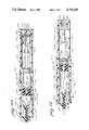
- FIG. 1is a longitudinal sectional view of an automatic mixing and injecting apparatus embodying the principles of the present invention showing the parts in their storage position;
- FIG. 2is a view similar to FIG. 1 showing the parts in their mixing or liquid medicamant forming position;
- FIG. 3is a view similar to FIG. 1 showing the parts in their final injecting position
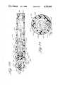
- FIG. 4is a sectional view taken along the line 4--4 of FIG. 1;
- FIG. 5is a view similar to FIG. 1 of another form of automatic mixing and injecting apparatus embodying the principles of the present invention
- FIG. 6is a sectional view taken along the lines 6--6 of FIG. 5;
- FIG. 7is view similar to FIG. 1 of still another form of automatic mixing and injecting apparatus embodying the principles of the present invention
- FIG. 8is a view similar to FIG. 2 of the apparatus shown in FIG. 7;
- FIG. 9is a view similar to FIG. 3 of the apparatus shown in FIG. 7;
- FIG. 10is a view similar to FIG. 1 of still another form of automatic mixing and injecting apparatus embodying the principles of the present invention
- FIG. 11is a view similar to FIG. 2 of the apparatus shown in FIG. 10;
- FIG. 12is a view similar to FIG. 3 of the apparatus shown in FIG. 10, and
- FIG. 13is a sectional view taken along the lines 13--13 of FIG. 10.
- FIG. 1an automatic injector or mixing and injecting apparatus, generally indicated at 10, which embodies the principles of the present invention.
- the apparatus 10includes an outer housing assembly 12 having an inner housing structure 14 mounted therein for rectilinear sliding movement from a storage position, as shown in FIG. 1, forwardly into an injecting position, as shown in FIG. 3.
- Inner housing structure 14has connected thereto a hypodermic needle assembly 16.
- a first liquid medicament ingredient container assembly 18is operatively associated with the inner housing structure 14 and a side by side related second medicament ingredient container assembly 20 is likewise operatively associated with the inner housing structure 14.
- Operatively associated with the first and second container assemblies 18 and 20are first and second stressed spring assemblies 22 and 24.
- the first stressed spring assembly 22is mounted in a stressed condition on the inner housing structure 14 in operative relation with the first container assembly 18.
- the second stressed spring assembly 24is connected with the outer housing assembly 12 in a stressed condition in operative relation with the second container assembly 20.
- a safety cap and releasing pin assembly 26is mounted in operative relation with respect to the first and second spring assemblies 22 and 24 for rendering the apparatus inoperable and for enabling the first spring assembly to be released in response to a first predetermined actuating procedure and the second spring assembly to be released in response to a second actuating procedure.
- the outer housing assembly 12includes an elongated tubular housing member 28 having an integral rear wall 30 and an open forward end which has formed in the exterior periphery thereof an annular groove 32.
- a forward housing member 34includes a rearward annular skirt 36 having an annular ridge 38 formed on the interior periphery thereof for cooperatively engaging within the annular groove 32 so as to secure the two housing members together.
- the housing member 34also includes a forwardly projecting centrally apertured skin contacting portion 40.
- the inner housing structure 14includes a tubular member 42 having a ribbed exterior periphery which slidably engages the interior periphery of the outer housing member 28.
- the inner housing member 42also includes a rear wall 44 and, like the outer housing member 28, its forward end is open and has an annular groove 46 formed therein. This time the annular groove 46 is on the interior surface of the inner housing member 42 rather than the outer surface thereof as with the outer housing member 28.
- Fixedly mounted within the open forward end of the inner housing member 42is a forward inner housing member 48.
- the inner housing member 48includes an integral needle element 50 extending forwardly from the central portion thereof which constitutes part of the hypodermic needle assembly 16.
- the needle assembly 16also includes a resilient sheath 52 the forward end of which engages within the central opening in the skin engaging portion 40 of the outer housing assembly 12.
- the tip of the resilient sheath 52closes the forward central aperture of the outer housing assembly 12 and seals the sharp piercing end of the needle element 50.
- the needle element 50is of the hypodermic type including an interior passage 54 for the conveyance of a liquid medicament outwardly thereof into the muscle tissue of the patient.
- the rearward end of the needle passage 54connects with a cross passage 56 formed in the forward inner housing member 48.
- one end of the cross passage 56is plugged, as indicated at 58, and at a position spaced from the plug, the cross passage 56 communicates with a first rearwardly extending passage 60 which is formed in a first rearwardly projecting cylindrical portion 62 having a rearwardly extending diaphragm piercing element 64 integral therewith.
- the opposite end of the cross passage 56connects with a second rearwardly extending passage 66 formed in a second rearwardly extending cylindrical portion 68 which terminates in a diaphragm piercing element 70.
- the member 48includes in addition a rearwardly extending peripheral skirt 72 having an exterior annular ridge 74 thereon which is adapted to cooperate with the annular groove 46 to secure the forward inner housing member 48 with the tubular inner housing member 42.
- the first and second container assemblies 18 and 20include first and second containers 76 and 78 which, as shown, are formed of plastic material although they may be formed of glass if desired.
- the first and second containers 76 and 78are arranged to engage within a container support structure, generally indicated at 80.
- the container support structure 80includes a peripheral wall 82 which includes exterior surfaces which engage with the interior periphery of the inner housing member 42 for sliding movement with respect thereto from a storage position, as shown in FIG. 1, to a mixing or liquid medicament forming postion, as shown in FIG. 2.
- the container support structure 80includes a first bore 84 which extends forwardly from the rearward end thereof and terminates in an annular shoulder 86 so as to receive the first container 76 forwardly therein.
- the first containeris formed by a cylindrical wall which is open at its rearward end and which has an exteriorly flanged necked down forward end, indicated at 88.
- a piercable diaphragm 90is mounted on the forward end of the exteriorly flanged necked down end 88 and is retained thereon by a hub assembly 92 which includes a rearward portion extending over the exterior annular flange of the container and a forward portion of reduced diameter which slidably sealingly engages the associated rearwardly projecting cylindrical portion 62 of the inner housing member 48.
- the container support structure 80also includes a second cylindrical bore 94 which extends rearwardly from the forward end thereof and terminates in a rearward inwardly directed annular shoulder 96 so as to receive the second container 78 rearwardly therein.
- the second container 78is similar to the first and includes an open rear end and an exteriorly flanged necked down open forward end 98 which is closed by a piercable diaphragm 100 retained thereon by hub assembly 102 having a rearward portion fixed to the exterior flange and a forward portion of reduced diameter slidably sealingly engaging the associated rearwardly extending cylindrical portion 68.
- a liquid medicament ingredient 104which is sealed at its forward end by the associated piercable diaphragm and at its rearward end by a piston 106 formed of resilient material which is slidably sealingly mounted within the rearward interior end portion of the container 76.
- the second container 78has mounted therein a medicament ingredient 108 which, as shown, is in dry form and more specifically a freeze dried powder.
- the forward end of the medicament ingredient 108is sealed by the associated diaphragm 100 and its rearward end is sealed by a piston 110 which is constructed similarly to the piston 106 previously described.
- the second piston 110is disposed near the forward end portion of the second container 78 in its storage condition, the remaining portion of the second container disposed rearwardly of the piston 110 desirably should be maintained in a sterile condition since it is to receive liquid medicament when the second piston 110 is moved rearwardly from its storage position to a position enabling the liquid medicament to be moved forwardly.
- a sealing piston 112which has venting slots 114 formed in the forward portion thereof.
- the first stressed spring assembly 22includes a hollow plunger 116 the forward end of which is flanged, as indicated at 118, and disposed in engagement with the first piston 106 forming a part of the first container assembly 18.
- the rearward portion of the plunger 116is slotted, as indicated at 120, to form a plurality of annularly spaced resilient fingers 122 which are integral with the plunger.
- the fingers 122are formed with exterior plunger retaining surfaces 124 which face forwardly and outwardly and extend at an angle of approximately 45° .
- the rearward end wall 44 of the inner housing member 42is apertured to receive the plunger and is provided with cooperating interior plunger retaining surfaces 126 which face inwardly and rearwardly and extend at an angle of approximately 45°.
- the fingers 122 of the plunger 116are also provided with a series of interior plunger releasing surfaces 128. These surfaces are disposed within a common cylindrical plane which has a diameter substantially less than the interior diameter of the hollow plunger.
- the interior plunger releasing surfacesextend from the rearward end of the fingers inwardly a short distance.
- Mounted within the interior plunger releasing surfaces 128 of the fingers 122is a first releasing pin 130 which, as shown, forms a part of the safety cap and releasing assembly 26.
- the releasing pin 130when the releasing pin 130 is disposed in engagement with the interior plunger releasing surfaces 128 the associated fingers 122 are prevented from being deflected radially inwardly.
- the releasing pin 130thus serves to insure that the exterior plunger retaining surfaces 124 of the fingers 122 will be maintained in engagement with the cooperating plunger retaining surfaces 126 of the inner housing structure 14. This maintenance is provided notwithstanding the bias which is present by virtue of a stressed coil spring 132 forming a part of the spring assembly 22.
- Coil spring 132is mounted over the exterior periphery of the plunger 116 with its forward end in engagement with the flange 118 and its rearward end in engagement with the forwardly facing surface of the rearward end wall 44 of the inner housing structure 14.
- the end wall 44In order to center the coil spring 132, preferably the end wall 44 is provided with an integral forwardly extending cylindrical skirt portion 134 which surrounds the rearward end portion of the coil spring 132.
- the second stressed spring assembly 24is similar to the first in that it includes a hollow plunger 136 having a flange 138 on the forward exterior periphery thereof and slots 140 formed in the rearward end portion thereof so as to define a series of annularly spaced radially inwardly deflectable spring fingers 142.
- the spring fingers 142include exterior plunger retaining surfaces 144 and interior plunger releasing surfaces 146.
- the rearward end wall 30 of the outer housing member 28is apertured to receive the second plunger 136 and includes cooperating rearwardly and inwardly facing plunger retaining surfaces 148.
- the end wall 30is also apertured, as indicated at 150, to allow free movement of the first plunger 116 therethrough.
- end wall 44 of the inner housing member 42is apertured, indicated at 152, to receive a forwardly extending skirt 154 which surrounds the rearward end portion of a stresed coil spring 156, the forward end of which engages the flange 138 and the rearward end of which engages the forward surface of the end wall 30 of the outer housing member 28 surrounded by the skirt 154.
- the releasing pin 158is of the type adapted to release the spring fingers 142 either when moved forwardly or rearwardly with respect to the rear end of the associated spring fingers. As shown, the releasing pin 158 includes a forward movement preventing portion 160 which has a diameter sufficient to engage with the interior plunger releasing surfaces 146 so as to be disposed in engagement therewith when the plunger 136 is in its storage position.
- the releasing pin 158also includes an actuating button 162 spaced rearwardly from the movement preventing portion 160 and movable forwardly to move the latter out of its storage position into a releasing position or movable rearwardly to remove the movement preventing portion 160 from its storage position.
- the releasing pin 158includes a movement preventing portion 164 of reduced diameter fixed between the movement preventing portion 160 and the actuating button 162.
- the assembly 26also includes a safety cap 166 which is formed as an end wall having an annular skirt extending forwardly thereof. The forward end of the skirt is recessed so as to engage over the rearward end portion of the outer housing member 28 and to provide an annular shoulder 168 which engages the marginal peripheral portion of the rear wall 30. As shown, the releasing pin 130 is detachably fixed with the end wall of the safety cap 166, as by a screw 170.
- the apparatus 10is assembled by first assembling the first stressed spring assembly 22 in operative relation with the end wall 44 of the inner housing member 42. This is accomplished by moving the plunger 116 rearwardly within the inner housing member 42 until the rearward end of the plunger fingers 122 engaged through the opening defined by the plunger retaining surfaces 126. The releasing pin 130 is then inserted within the fingers 122 to prevent them from moving radially inwardly. In this way the plunger 116 is prevented from moving forwardly by virtue of the intergagement between the plunger retaining surfaces 124 and 126 thus retaining the coil spring 132 in its stressed condition. Similarly, the second stressed spring assembly 24 is mounted in operative relation with respect to the outer housing member 28 utilizing releasable pin 158.
- the safety cap 166is engaged into its storage position and screw 170 is threaded into secured relation within the releasing pin 130 so that the latter will be moved out of its storage position in response to the rearward movement of the safety cap 166 out of its storage position, as shown in FIG. 1.
- the containers 76 and 78are separately filled with the respective medicament ingredients 104 and 108 and sealed with the diaphragms 90 and 100 by the hub assemblies 92 and 102 at their forward ends and with the pistons 106 and 110-112 at their rearward ends.
- the two containersare mounted within the container support structure 80 and then the hub assemblies 92 and 102 are moved into an initial position with respect to the cylindrical portions 62 and 68 of the member 48.
- the resilient sheath 52has been mounted over the needle element 50 the entire unit containing the two container assemblies 18 and 20, the inner housing structure 14 and needle assembly 16 is moved rearwardly into the outer tubular housing member 28 and the forward housing member 36 is snapped over the forward end thereof to complete the assembly.
- the operatorTo operate the apparatus 10 the operator first moves the safety cap 166 out of its storage position, as shown in FIG. 1. This movement preferably is accomplished by simply pulling the cap 166 off of its engagement with the outer housing member 28. The removing of the safety cap 166 carries with it the safety pin 130 and this movement constitutes the first predetermined actuating movement which effects the release of the first stressed spring assembly 22.
- the angle of the plunger movement preventing surfaces 124 and 126are such that as soon as the releasing pin 130 is removed from its storage position, the stress of the spring 132 will effect sufficient forward movement of the plunger 116 to cause the spring fingers 122 to be moved radially inwardly until the surfaces 124 disengage from the surfaces 126 and then the stressed spring 132 is capable of advancing the plunger 116 forwardly through an operative stroke.
- the initial forward movement of the plunger 116will result in a forward movement of the entire container 76 and the container support structure 80 by virtue of the engagement of the forward shoulder 86 thereof with the container 76.
- this forward movement of the container support structure 80has the effect of moving the second container 78 forwardly by virtue of the rearward flange 96.
- the initial movement of the plunger 116results in a forward movement of both containers 76 and 78 and the container support structure 80.
- the hub assemblies 92 and 102telescope with respect to the cyclindrical portions 62 and 68 allowing the associated diaphragms 90 and 100 to move fowardly in piercing relation to the associated piercing elements 64 and 70.
- Forward movement of the two containers and container support structure togetheris positively limited by the engagement of the forward end of the hub portions 92 and 102 with the rear surface of the inner housing member 48 which in turn is held against forward movement by the engagement of the needle assembly 16 with the outer housing assembly 12.
- the flanged end 138 of the second plunger 136assumes a position rearwardly of the second container 78 by virtue of the aforesaid forward movement of the second container 78 with the container support structure 80 during the initial movement of the first plunger 116. Consequently, as the forward piston 110 moves rearwardly, the air trapped between the forward piston 110 and the vent piston 112 tends to increase in pressure thus causing the vent piston 112 to be moved rearwardly into a position of engagement with the flanged end 138 of the second plunger 136.
- the vent slots 114vent the interior space of the container 78 rearwardly of the piston 110 to atmosphere thus enabling the same to move rearwardly as the liquid medicament ingredient from the first container flows into the second container.
- the vent slots 114vent the interior space of the container 78 rearwardly of the piston 110 to atmosphere thus enabling the same to move rearwardly as the liquid medicament ingredient from the first container flows into the second container.
- Injectionis accomplished in response to a second predetermined actuating procedure which includes the operator gripping the exterior periphery of the outer housing member 28 and moving the nose portion 40 into engagement with the patient's skin in the area which is to receive the injection, as for example, the thigh.
- actuating button 162the operator simply pushes forwardly on the actuating button 162, as with the thumb, which has the effect of releasing the second stressed spring assembly 24.
- the movement of the releasing pin 158 out of its storage positionpermits the stressed spring 156 biasing the plunger 136 forwardly to effect a radially inward movement of the plunger fingers 142 by virtue of the interengagement between the plunger retaining surfaces 144 and 148.
- the forward flanged end 138 of the plunger 136 in engagement with the vent piston 112tends to move the latter forwardly which in turn is in engagement with the piston 110 acting on the rear end of the liquid medicament within the container 78.
- the initial movement of the plungertherefore applies a force to the liquid medicament which tends to cause the same to move outwardly of the second container and into the passage 66.
- the resistance to the movement of the sharpened forward end of the needle element 50 and the entire inner housing assembly 14 including the two container assemblies 18 and 20 carried therebyis less than the hydraulic resistance and consequently, the applicaton of the force of spring 156 through the plunger 136, pistons 112 and 110 to the liquid medicament in the second container 78 is transmitted to the inner housing assembly 14 through the engagement of the hub assemblies 92 and 102 with the member 48, results in the movement of the needle element 50 forwardly through the resilient sheath 52 and outwardly of the outer housing portion 40 into the muscle tissue of the patient.
- the forward movement of the inner housing assembly 14 with respect to the outer housing assembly 12is arrested by virtue of the compression of the resilient sheath 52.
- continued forward movement of the plunger 136 under the bias of the spring 156serves to advance the two pistons 112 and 110 within the container 78 thus expelling the liquid medicament therein outwardly through the passage 66, the cross passage 56 and the passage 54 in the needle element 50 into the muscle tissue of the patient.
- substantially the entire amount of the liquid medicament within the second container 78is injected into the muscle tissue of the patient, as shown in FIG. 3.
- the operatorsimply withdraws the needle element 50 from the patient.
- FIGS. 5 and 6 of the drawingsthere is shown therein another form of apparatus, generally indicated at 210 which embodies the principals of the present invention.
- the apparatus 210is similar to the apparatus 10 except that the containers are fixed with respect to the inner housing structure and the safety cap and the releasing assembly is of a different form.
- the apparatus 210includes an outer housing assembly 212, an inner housing structure 214 mounted within the outer housing assembly for movement forwardly from a storage position into an injecting position.
- a hypodermic needle assembly 216is fixed to the forward central portion of the inner housing structure 214 within the outer housing assembly 212 in a sterile condition disposed in a storage position when the inner housing structure 214 is in its storage positon and capable of moving outwardly of the outer housing assembly 212 with the inner housing structure 214 for movement into the muscle tissue of a patient when the inner housing structure moves into its injecting position.
- a first medicament container assembly 218 and a side-by-side second medicament container assemblyare illustrated at 220.
- a first stressed spring assemblyOperatively associated with the first medicament container assembly 218 and with the inner housing structure 214 is a first stressed spring assembly, generally indicated at 222.
- a second stressed spring assembly 224is operatively connected with the second medicament container assembly 220 and with the outer housing assembly 212.
- a safety cap and releasing assemblyis provided in a storage position for rendering the first and second stressed spring assemblies 222 and 224 incapable of being released. When moved out of its storage position the assembly 226 enables the first stressed spring assembly 222 to be released in response to a first predetermined actuating procedure and then the second stressed spring assembly 224 to be released in response to a second predetermined actuating procedure.
- the outer housing assembly 212is similar to the outer housing assembly 12 previously described in that it includes a main tubular outer housing member 228 having a rear end wall 230 at its rearward end and being open at its forward end. The forward end is closed by a forward housing member 232 which includes a rearwardly extending annular skirt having an interior annular ridge formed therein for engaging within a cooperating annular groove formed in the periphery of the forward end portion of the outer housing member 228.
- the forward outer housing member 232also includes a forwardly projecting skin engaging nose portion 234 which is centrally apertured to permit movement of a needle 236 therethrough forming a part of the needle assembly 216.
- the inner housing structure 214includes an inner tubular housing member 238 having an exterior peripheral configuration to slidably engage within the interior peripheral configuration of the outer housing member 228.
- the inner housing memberincludes an end wall 240 at its rearward end and, like the outer housing member 228 is open at its forward end.
- the inner housing structure 214includes an inner housing member 242 which provides a forward wall having an exterior annular ridge for engaging within an interior peripheral groove formed on the forward end portion of the inner housing member 242.
- the inner housing member 242also includes a rearwardly extending portion defining a first container 244 extending rearwardly within the housing member 234 and a second container 246 in side-by-side relation with respect to the first container 244.
- the hypodermic needleis of conventional metal configuration having a sharpened forward edge which is engaged within the tip of a resilient sheath 248 so as to close off communication of the hollow interior thereof.
- the rearward end of the needlecommunicates with a rearwardly extending passage 250 which is formed in the central forward portion of the inner housing member 242.
- the rearward end of the passage 250communicates with the intermediate portion of a cross passage 252, one end of which communicates with the forward end of a passage 254 extending rearwardly in communication with the interior of the first container 244.
- the first container 244includes therein a liquid medicament ingredient 256 which is sealingly confined rearwardly by a piston 258 of suitable resilient material so as to be slidably sealingly mounted within the container 244.
- the opposite end of the cross passage 252communicates with a counterbore 260 formed in the forward portion of the member 242.
- the end of the counterbore 260is closed by a detachable plug 262.
- a piston valve 264mounted within the counterbore 260 is a piston valve 264 which, as shown in FIG. 5, is disposed in a storage position closing off communication between the associated end of the cross passage 252 and a short passage 266 extending from the counterbore rearwardly into communication with the second container 246.
- a medicament ingredient 268which preferably is in dry form, specifically a freeze dried powder.
- the medicament ingredient 268is sealingly retained within the second container by a piston 270 which is of suitable resilient material like the piston 258 previously described.
- vent piston 272Mounted in the rearward end portion of the second container 246 in rearwardly spaced relation to the forward piston 270 is a vent piston 272.
- the vent piston 272is normally disposed in a storage position spaced inwardly from the rearward end of the second container 246.
- Formed in the interior periphery of the rearward end portion of the second container 246is a plurality of annularly spaced vent grooves 274 which extend from the rearward end portion of the piston 272 to the rearward end of the second container 246.
- the first stressed spring assembly 222includes a hollow plunger 276 the forward end of which is flanged, as indicated at 278, and disposed in engagement with the first piston 258 forming a part of the first container 218.
- the rearward portion of the plunger 276is slotted, as indicated at 280, to form a plurality of annularly spaced resilient fingers 282 which are integral with the plunger.
- the fingers 282are formed with exterior plunger retaining surfaces 284 which face forwardly and outwardly and extend at an angle of approximately 45°.
- the rearward end wall 240 of the inner housing member 238is apertured to receive the plunger 276 and is provided with cooperating interior plunger retaining surfaces 286 which face inwardly and rearwardly and extend at an angle of approximately 45°.
- the fingers 282 of the plunger 276are also provided with a series of interior plunger releasing surfaces 288. These surfaces are disposed within a common cylindrical plane which has a diameter substantially less than the interior diameter of the hollow piston.
- the interior plunger releasing surfaces 288extend from the rearward end of the fingers inwardly a short distance.
- Mounted within the interior plunger releasing surfaces 288 of the fingers 282is a first releasing pin 290 which, as shown, forms a part of the safety cap and releasing assembly 226.
- the releasing pin 290when the releasing pin 290 is disposed in engagement with the interior plunger releasing surfaces 288 the associated fingers 282 are prevented from being deflected radially inwardly.
- the releasing pin 290thus serves to insure that the exterior plunger retaining surfaces 284 of the fingers 282 will be maintained in engagement with the cooperating plunger retaining surfaces of the inner housing structure 214. This maintainance is provided notwithstanding the bias which is present by virtue of a stressed coil spring 292 forming a part of the spring assembly 222.
- Coil spring 292is mounted over the exterior periphery of the plunger 276 with its forward end in engagement with the flange 278 and its rearward end in engagement with the forwardly facing surface of the rearward end wall 240 of the inner housing structure 214.
- the end wall 240is provided with an integral forwardly extending cylindrical skirt portion 294 which surrounds the rearward end portion of the coil spring 292.
- the second stressed spring assembly 224is similar to the first in that it includes a hollow plunger 296 having a flange 298 on the forward exterior periphery thereof and slots 300 formed in the rearward end portion thereof so as to define a series of annularly spaced radially inwardly deflectable spring fingers 302.
- the spring fingers 302include exterior plunger retaining surfaces 304 and interior plunger releasing surfaces 306.
- the rearward end wall 320 of the outer housing member 228is apertured to receive the second plunger 296 and includes cooperating rearwardly and inwardly facing plunger retaining surfaces 308.
- the end wall 230is also apertured to allow free movement of the first plunger 276 therethrough.
- end wall 240 of the inner housing member 238is apertured to receive a forwardly extending skirt 309 which surrounds the rearward end portion of a stressed coil spring 310, the forward end of which engages the flange 298 and the rearward end of which engages the forward surface of the end wall 230 of the outer housing member 228 surrounded by the skirt 309.
- the releasing pin 312is of the type adapted to release the spring fingers 302 either when moved forwardly or rearwardly with respect to the rear end of the associated spring fingers. As shown, the releasing pin 312 includes a forward movement preventing portion 314 which has a diameter sufficient to engage with the interior plunger releasing surfaces 306 so as to be disposed in engagement therewith when the plunger 296 is in its storage position.
- the releasing pin 312also includes an actuating button 316 spaced rearwardly from the movement portion 314 and movable forwardly to move the latter out of its storage position into a releasing position or movable rearwardly to remove the movement preventing portion 314 from its storage position.
- the releasing pin 312includes a movement enabling portion 318 of reduced diameter fixed between the movement preventing portion 314 and the actuating button 316.
- the assembly 226also includes a safety key 320 and a safety cap 322 which is formed as an end wall having a manually engagable annular skirt 324 extending forwardly thereof over a substantial portion of the outer housing member 228.
- the key 320is in the form of a rearward wall which is integrally connected with the rear end of the pin 290.
- the key 320also includes a cylindrical wall portion 326 extending forwardly from the rear wall and a keyed or dual lug shaped wall portion 328 extending forwardly from the portion 326.
- a keyed or dual lug shaped opening 330Formed in the rear wall of the safety cap 322 is a keyed or dual lug shaped opening 330 of a size to receive the keyed portion 328 therethrough which is rotationally aligned therewith. It will be noted however that when the safety key 320 is turned into the storage position shown so as to be rotationally out of alignment, the keyed portion 328 extends between the cap end wall and the outer housing member end wall so as to prevent forward movement of the cap 322 out of its storage position as shown.
- the apparatus 210is assembled by first assembling the first stressed spring assembly 222 in operative relation with the end wall 240 of the inner housing member 238. This is accomplished by moving the plunger 276 rearwardly within the inner housing member 238 until the rearward end of the plunger fingers 282 engage through the opening defined by the plunger retaining surfaces 286. The releasing pin 290 carried by the safety key 320 is then inserted within the fingers 282 to prevent them from moving radially inwardly. In this way the plunger 276 is prevented from moving forwardly by virtue of the interengagement between the plunger retaining surfaces 284 and 286 thus retaining the coil spring 292 in its stressed condition.
- the second stressed spring assembly 224is mounted in operative relation with respect to the outer housing member 228 utilizing releasable pin 312.
- the safety cap 322is engaged into its storage position with skirt 324 extending over the outer housing member 228 and with the opening 330 receiving the portion 326 of the key 320. Forward movement of the cap is stopped by the engagement of the keyed portion 328 of the safety key 320 between the cap rear wall and the housing member rear wall.
- the containers 244 and 246are separately filled with the respective medicament ingredients 256 and 268 and sealed by the piston valve 266 and plug 262 at their forward ends and with the pistons 258 and 270-272 at their rearward ends.
- the housing member 242 defining the two containersis mounted within the inner housing member 238 and needle 236 is mounted in place.
- the resilient sheath 248has been mounted over the needle 236, the entire unit containing the two container assemblies 218 and 220, the inner housing structure 214 and needle assembly 216 is moved rearwardly into the outer tubular housing member 228 and the housing member 232 is snapped over the forward end thereof to complete the assembly.
- the operatorTo operate the apparatus 210 the operator first turns the safety key 320 and moves it rearwardly out of its storage position, as shown in FIG. 5. The removal of the safety key 320 carries with it the safety pin 290 and this movement constitutes the first predetermined actuating procedure which effects the release of the first stressed spring assembly 222.
- the angle of the plunger movement preventing surfaces 284 and 286are such that as soon as the releasing pin 290 is removed from its storage position, the stress of spring 292 will effect sufficient forward movement of the plunger 276 to cause the spring fingers 282 to be moved radially inwardly until the surface 284 disengages from the surface 286 and then the stressed spring 292 is capable of advancing the plunger 276 forwardly through an operative stroke.
- the force of the released stressed spring 292serves to increase the pressure within the liquid medicament ingredient 256.
- This pressureis transmitted to the inner housing member 242 and the liquid within the passage 254 and cross passage 252 therein.
- the force required to effect movement of the piston valve 264is considerably less than the force required to effect movement of the entire inner housing member 214 and consequently the piston valve 264 will be moved into a position uncovering the passage 266 so as to allow the pressurized liquid medicament ingredient 256 to pass into the second container 246 to mix with the medicament ingredient 268 therein.
- piston 270will be moved rearwardly. This movement in turn causes the air rearwardly of the piston to increase and this increase in pressure in turn builds up until it is sufficient to effect a rearward movement of the vent piston 272.
- the vent piston 272moves rearwardly until it engages the forward flanged end 298 of the plunger 296. In this position vent grooves 274 are communicated with the space within the second container 246 forwardly of the vent piston 272 thus exhausting the pressure to atmosphere and allowing the piston 270 to move freely rearwardly in response to the flow of liquid mediqament ingredient 256 from the first container into the second container.
- the actuating procedureincludes grasping the skirt 324 of the safety cap 322 and moving the nose portion 234 of the outer housing assembly 212 into engagement with the skin of the patient in the area which is to receive the injection, as for example, the thigh. Continued forward movement on the skirt 324 has the effect of effecting the forward movement of the latter with respect to the outer housing assembly 212 during which movement the rear wall of the safety cap 226 will engage the actuating button 312 and move the same forwardly until movement preventing portion 314 thereof is disengaged from the movement preventing surfaces 306 of the spring fingers.
- FIGS. 7 through 9there is shown therein still another form of automatic injecting apparatus, generally indicated at 410 which embodies the principles of the present invention.
- the apparatus 410differs from the apparatus 10 and the apparatus 210 previously described in that the injecting function is accomplished in accordance with the structural and functional principles enunciated in commonly assigned U.S. Pat. No. 3,396,726, the disclosure of which is hereby incorporated by reference into the present specification.
- the apparatus 410consists essentially of a plural cartridge assembly, generally indicated at 412, a plural releasable stressed spring assembly, generally indicated at 414, and a safety cap and releasing pin assembly, generally indicated at 416.
- the plural cartridge assembly 412includes a housing member 418 which is in the form of a molded plastic body providing a first cylindrical cavity 420 which is open at its rearward end and closed at its forward end except for a central vent opening 422.
- the housing member 418also provides a second cylindrical cavity 424 which is open at its rearward end and closed at its forward end except for a central opening 426.
- Formed in the portion of the housing member 418 defining the forward end portion of the first cavity 420is a bore 428 which extends transversely through the periphery of the housing body radially inwardly into the cavity 420 and radially outwardly thereof into the second cavity 424 at a position spaced from the forward end thereof.
- a piston valve 430which in its storage position, shown in FIG. 7, extends forwardly and rearwardly of the bore 428 so that its forward surface is spaced from the forward end of the cavity 420.
- a plug 432is formed in the outer portion of the bore 428 so as to close off the same and prevent flow of liquid outward of the first cavity therethrough.
- the piston valve 430which is molded of a suitable resilient material, as for example, an elastomeric resin or rubber, defines phe end of a medicament container within the housing member 418 within which a liquid medicament ingredient 434 is contained.
- the rearward end of the liquid medicament ingredient 434is confined by a piston 436 which, like the piston valve 430, is formed of a suitable resilient material.
- a spacer 438Detachably secured by the piston 436 and extending rearwardly therefrom is a spacer 438 having its rearward end disposed adjacent the rearward open end of the first cavity 420.
- a piston or plug member 440 of resilient materialwithin which is received the sharpened end of a hypodermic needle 442, as by an inset fitting 444.
- the hypodermic needle 442is hollow and includes a lateral opening 446 in its rearward end portion and a flattened disk-like element 448 on its rearward end which is disposed in engagement with a piston 450 similar to the piston 436.
- the second cavity 424, between the forward piston plug 440 and rearward piston 450,defines a second medicament container within which is mounted a medicament ingredient 452 preferably in the form of a dry powder although it may be in liquid form if desired.
- a disk shaped flap valve element 454mounted in the open rear end of the second cavity 424 is a disk shaped flap valve element 454 which acts as a sterility check valve for the portion of the cavity 424 between the valve element 454 and the piston 450.
- the rearward exterior periphery of the housing member 418is recessed and formed with an annular groove 456.
- the plural stressed spring assembly 414includes a housing member 458 which, like the housing member 418, is in the form of a molded plastic body which includes an interiorly ridged peripheral skirt 460 extending from the forward end thereof for engagement within the groove 456 as by a snap fit.
- the two housing members 418 and 458once assembled constitute an outer housing assembly of the apparatus 410.
- the housing member 458 of the spring assembly 414is formed with two cylindrical cavities 462 which are open at their forward ends and partially closed at their rearward ends as by centrally apertured rear wall portions 464.
- the assembly 414further includes components which make up two stressed spring assemblies similar to the stressed spring assemblies 22 and 24 and 222 and 224 previously described.
- each of the two stressed spring assembliesincludes a plunger 466 having a flanged forward end 468 and a split rearward end portion defining radially inwardly deformable fingers 470 having exterior plunger retaining surfaces 472 and interior plunger releasing surfaces 474.
- the apertured rear wall portions 464are formed with corresponding plunger retaining surfaces 476 and a stressed coil spring 478 surrounds each plunger 466 with its ends engaging the associated flanged forward end 468 thereof and the associated rear wall portion 464.
- the safety cap and releasing pin assembly 416is similar to the assembly 226 previously described.
- a safety key 480 having an integral releasing pin 482 engageable with the releasing surfaces 474 of the first plunger 466is provided and a second releasing pin 484 similar to the releasing pin 312 previously described is mounted in operative relation with respect to the releasing surfaces 474 of the second plunger 466.
- the assembly of the automatic injecting apparatus 410will be readily apparent in that the cartridge assembly 412 is assembled with the components thereof being inserted forwardly into the cavities 420 and 424 from the rear end thereof while the spring assemblies are assembled in the housing member 458 by moving the components rearwardly into the forward end of the cavaties 462. Once the releasing pins 482 and 484 are in place, the two housing members 418 and 458 are snapped together and then the safety cap 486 is moved over the rear of the entire assembly.
- the apparatus 410is operated in a manner similar to the apparatus 210 in that the first manual actuating procedure is to turn and remove the safety key 480 which releases the first stressed spring 478.
- the release of the first springaccomplishes the mixing of the liquid medicament ingredient 434 with the powder medicament ingredient 452.
- the second manual actuating procedureis for the operator to grasp the elongated safety cap skirt 488 and move the forward end of the outer housing assembly into engagement with the skin of the patient at the location where the injection is to take place.
- the hypodermic needle 442is extended into the muscle tissue of the patient and the liquid medicament which has previously been formed is injected through the needle 442 into the muscle tissue of the patient.
- the piston 450moves rearwardly the air within the space within the cavity 424 between the piston 450 and the flap valve element 454 will increase slightly to a value which is sufficient to cause the flap valve element 454 to move rearwardly and communicate the space rearwardly of the piston 450 with the atmosphere.
- the piston 450is capable of being moved rearwardly into a position of engagement with the forward end of the valve element 454 and the plunger end 468 without generating any air pressure acting in a direction to move the piston 450 forwardly.
- the air within the second containerwill be compressed forwardly of the piston 450.
- Such air compressionwill continue to occur as the piston 450 moves forwardly until such time as the pressure reaches a value sufficient to cause flow of liquid out of the container through the bore 428 into the first cavity 420 moving the piston 436 back against the residual spring pressure of the first spring 478.
- the arrangementis such that it is preferable that when the piston 450 reaches the rear end of the hypodermic needle there will be a pocket of air forwardly of the piston whose axial dimension is equal to the distance the sharpened end of the needle 442 must travel to enter within the muscle tissue of the patient.
- the containment of such a volume of airmay require the outflow of liquid medicament from the second container through the bore 428 into the first container.
- FIGS. 10 through 13there is shown therein still another form of an automatic injecting apparatus, generally indicated at 510, which embodies the principles of the present invention.
- the apparatus 510exemplifies that the principles of the present invention can be carried out with only one stressed spring assembly and with the medicament ingredient containers disposed in arrangements other than side by side.
- the containersare telescopically mounted and it will be understood that other arrangements can be utilized in practicing the principles of the present invention.
- the apparatus 510includes an outer housing assembly, generally indicat.de at 512 within which is mounted a dual container cartridge assembly 514 and a single stressed spring assembly 516.
- the apparatus 510also includes a safety cap and releasing pin assembly 518 which is operable in response to a first predetermined manual actuating procedure to effect a first release of the stressed spring assembly 516 for effecting the mixing function and a second releasing assembly 520 operable in response to a second predetermined manual actuating procedure to effect a second release of the stressed spring assembly 516 for effecting the injecting function.
- the outer housing assembly 512includes a tubular housing member 522 in the form of a cylinder having an open forward end and a rearward end closed by an end wall 524 having a central opening therein.
- the housing assembly 512also includes a forward housing member 526 which includes a rearwardly extending skirt 528 having a snap connection over the exterior periphery of the forward end of tubular frame member 522 and a central forwardly extending nose portion 530 which is centrally apertured.
- the dual container cartridge assembly 514includes an outer container 532 which is in the form of a cylindrical container open at its rearward end and having a necked down exteriorly flanged forward end.
- a hub assembly 534serves to connect the rear end of a hypodermic needle 536 in communicating relation with the forward necked down end of the container 532.
- a resilient sheath 538is fixed over the hypodermic needle 536 and its tip serves to sealingly retain liquid within the hypodermic needle 536 while in its storage condition and to retain the hypodermic needle in a sterile condition.
- a medicament ingredient 540preferably in the form of dry powder.
- the medicament ingredient 540is confined at its rearward end by a large piston 542 which has a deep recess 544 formed in the rear end portion thereof so as to define a thin forward central portion in the piston 542.
- an inner container 546mounted within the outer container 532 rearwardly of the piston 542 is an inner container 546 which is of a configuration similar to the configuration of the container 532 but of smaller diameter.
- the necked down exteriorly flanged forward end portion of the inner container 546is connected, as by a hub assembly 548 to a short needlelike element 550, the sharpened end of which is embedded within the central thin wall portion of the piston 542 so as to provide a liquid seal thereof.
- a liquid medicament ingredient 552which is confined at its rear end by a piston 554 of resilient material.
- a blowout ring seal 556provided in the rear end of the two containers 532 and 546 for maintaining the interior of the outer container 532 between the rear seal 556 and the piston 542 in a sterile condition when the apparatus 510 is in its storage position, as shown in FIG. 10.
- the stressed spring assembly 516includes an elongated plunger 558 having a flanged forward end 560 arranged to be disposed in engagement with the piston 554 and an intermediate flange 562 for receiving one end of a stressed coil spring 564, the opposite end of which engages the rear end wall 524 of the outer tubular housing member 522.
- the rear end portion of the plunger 558is slotted to form a plurality of spring fingers 566 which have plunger retaining surfaces 568 arranged to be engaged with a frustoconical plunger retaining surface 570 in the end wall 524 and interior plunger releasing surfaces 572 which, as shown in FIG. 10, engage the exterior of a releasing pin 574 forming a part of the assembly 518.
- FIG. 10As best shown in FIG.
- the assembly 518includes a safety cap 576 which is in the form of an end wall having a forwardly extending skirt.
- the pin 574is integral with the central forward surface of the cap end wall and the skirt is recessed to engage over the exterior periphery of the rear end of the tubular housing member 522 and to provide a shoulder 578 to limit the forward movement of the cap 576 by engagement with the rear end wall 524.
- the second releasing assembly 520includes a manually engageable sleeve 580 slidably frictionally mounted over the exterior periphery of the outer housing member 522.
- a slot 582which registers with a smaller slot 584 formed in the peripheral wall of the tubular housing member 522.
- a releasing lock or bolt 586is slidably mounted in the slots 582 and 584 and has an angular slot 588 formed therein within which a pin 590 extends.
- Pin 590is fixed to the portion of the sleeve 580 defining slot 582, as is best shown in FIG. 13.
- the bolt 586in its locking or storage position, as shown in FIG. 10, extends into the interior of the housing member 522 and engages in front of an annular fitment 592 mounted forwardly of the outer container 546 at the position where it begins to neck down.
- apparatus 510is assembled in much the same manner as a conventional single dosage automatic injector of the type disclosed in U.S. Pat. Nos. 3,882,863 and 4,031,893.
- the operatorfirst removes the safety cap 576 which has the effect of withdrawing releasing pin 574.
- the angular relationship between the plunger retaining surfaces 568 and 570 and the strength of spring 564is such that movement of the plunger 558 commences in response to the withdrawal of the releasing pin 574.
- the spring fingers 566 of the plunger 558are cammed radially inwardly so as to allow the plunger 558 to move forwardly. The forward movement of the plunger is transmitted through the forward end 560 to the piston 554 which, in turn, is transmitted through the liquid medicament 552 to the inner container 546.
- blowout ring-shaped elements 556are moved rearwardly out of sealing relation between the ends of the inner and outer containers, allowing further rearward movement of the piston 542 within the outer container 532 to be accomplished without an increase in the air pressure in the space rearwardly of the piston 542 between the interior of the outer container 532 and the exterior of the inner container 546. Because the pressure area of the piston 542 is greater than the pressure area of the piston 554 the flow of liquid from the inner container 546 into the outer container 532 will continue until such time as the piston 554 reaches the forward end of the inner container 546. This position is shown in FIG. 11 and it will be noted that the spring 564 has expanded axially only a small amount and hence considerable stress remains in the coil spring.
- the operatorcan shake the unit to insure that the medicament ingredients are thoroughly mixed to form liquid medicament suitable to be injected.
- Injectionis accomplished by the operator gripping the outer periphery of the sleeve 580 and moving the nose portion 530 into engagement with the skin of the patient in the area where the injection is to take place as, for example, the thigh.
- the pin 590 carried therebyis moved forwardly with respect to the outer housing member 522.
- the apparatus 210In all of the embodiments of the present invention illustrated including the apparatus 10, the apparatus 210, the apparatus 410 and the apparatus 510, there is disclosed two separate medicament ingredients at least one of which is a liquid medicament ingredient.
- the other medicament ingredientis preferably in dry form, specifically a freeze dried powder, although it will be understood that the second liquid medicament may be in liquid form if desired.
- the liquid medicament which is formed in response to the first predetermined manual actuating proceduremay be any desired liquid medicament. Examples are disclosed in my commonly assigned U.S. application Ser. No. (735,311) filed concurrently herewith.
Landscapes
- Health & Medical Sciences (AREA)
- Animal Behavior & Ethology (AREA)
- Public Health (AREA)
- Anesthesiology (AREA)
- Biomedical Technology (AREA)
- Heart & Thoracic Surgery (AREA)
- Hematology (AREA)
- Engineering & Computer Science (AREA)
- Life Sciences & Earth Sciences (AREA)
- General Health & Medical Sciences (AREA)
- Vascular Medicine (AREA)
- Veterinary Medicine (AREA)
- Infusion, Injection, And Reservoir Apparatuses (AREA)
- Pharmaceuticals Containing Other Organic And Inorganic Compounds (AREA)
- Basic Packing Technique (AREA)
- Threshing Machine Elements (AREA)
- Medicinal Preparation (AREA)
Abstract
Description
Claims (12)
Priority Applications (1)
| Application Number | Priority Date | Filing Date | Title |
|---|---|---|---|
| US06/943,135US4755169A (en) | 1985-05-20 | 1986-12-18 | Automatic medicament ingredient mixing and injecting apparatus |
Applications Claiming Priority (2)
| Application Number | Priority Date | Filing Date | Title |
|---|---|---|---|
| US06/735,995US4689042A (en) | 1985-05-20 | 1985-05-20 | Automatic medicament ingredient mixing and injecting apparatus |
| US06/943,135US4755169A (en) | 1985-05-20 | 1986-12-18 | Automatic medicament ingredient mixing and injecting apparatus |
Related Parent Applications (1)
| Application Number | Title | Priority Date | Filing Date |
|---|---|---|---|
| US06/735,995DivisionUS4689042A (en) | 1985-05-20 | 1985-05-20 | Automatic medicament ingredient mixing and injecting apparatus |
Publications (1)
| Publication Number | Publication Date |
|---|---|
| US4755169Atrue US4755169A (en) | 1988-07-05 |
Family
ID=24958050
Family Applications (2)
| Application Number | Title | Priority Date | Filing Date |
|---|---|---|---|
| US06/735,995Expired - LifetimeUS4689042A (en) | 1985-05-20 | 1985-05-20 | Automatic medicament ingredient mixing and injecting apparatus |
| US06/943,135Expired - LifetimeUS4755169A (en) | 1985-05-20 | 1986-12-18 | Automatic medicament ingredient mixing and injecting apparatus |
Family Applications Before (1)
| Application Number | Title | Priority Date | Filing Date |
|---|---|---|---|
| US06/735,995Expired - LifetimeUS4689042A (en) | 1985-05-20 | 1985-05-20 | Automatic medicament ingredient mixing and injecting apparatus |
Country Status (15)
| Country | Link |
|---|---|
| US (2) | US4689042A (en) |
| EP (1) | EP0229820B1 (en) |
| JP (1) | JPS62502876A (en) |
| KR (1) | KR940006107B1 (en) |
| AT (1) | ATE91634T1 (en) |
| AU (1) | AU579301B2 (en) |
| CA (1) | CA1263576A (en) |
| DD (1) | DD245817A5 (en) |
| DE (1) | DE3688736T2 (en) |
| ES (1) | ES8707865A1 (en) |
| GR (1) | GR861290B (en) |
| IL (3) | IL97942A (en) |
| NZ (1) | NZ216166A (en) |
| PT (1) | PT82618B (en) |
| WO (1) | WO1986006967A1 (en) |
Cited By (197)
| Publication number | Priority date | Publication date | Assignee | Title |
|---|---|---|---|---|
| US4886495A (en)* | 1987-07-08 | 1989-12-12 | Duoject Medical Systems Inc. | Vial-based prefilled syringe system for one or two component medicaments |
| US5026349A (en)* | 1988-10-05 | 1991-06-25 | Autoject Systems Inc. | Liquid medicament injector system |
| US5085642A (en)* | 1989-07-17 | 1992-02-04 | Survival Technology, Inc. | Conveniently carried frequent use autoinjector |
| US5085641A (en)* | 1989-07-17 | 1992-02-04 | Survival Technology, Inc. | Conveniently carried frequent use auto-injector with improved cap structure |
| US5102393A (en)* | 1989-07-17 | 1992-04-07 | Survival Technology, Inc. | Autoinjector converted from intramuscular to subcutaneous mode of injection |
| US5122117A (en)* | 1990-06-05 | 1992-06-16 | Habley Medical Technology Corp. | Component mixing syringe |
| EP0494057A1 (en)* | 1990-11-30 | 1992-07-08 | Nesbitt D. Brown | Hydrolytic stabilizer for water soluble bis-quaternary pyridinium oximes |
| US5147323A (en)* | 1991-03-08 | 1992-09-15 | Habley Medical Technology Corporation | Multiple cartridge syringe |
| US5163929A (en)* | 1989-03-13 | 1992-11-17 | O.P.T.I.C., Inc. | Ocular vial |
| WO1993002720A1 (en)* | 1991-08-06 | 1993-02-18 | Senetek Plc | Medicament injector and method |
| US5199949A (en)* | 1991-03-08 | 1993-04-06 | Habley Medical Technology Corp. | Multiple pharmaceutical syringe |
| US5238927A (en)* | 1990-11-30 | 1993-08-24 | Brown Nesbitt D | Hydrolytic stabilizer for unstable organic ions |
| US5281198A (en)* | 1992-05-04 | 1994-01-25 | Habley Medical Technology Corporation | Pharmaceutical component-mixing delivery assembly |
| US5320609A (en)* | 1992-12-07 | 1994-06-14 | Habley Medical Technology Corporation | Automatic pharmaceutical dispensing syringe |
| US5354287A (en)* | 1991-01-16 | 1994-10-11 | Senetek Plc | Injector for delivering fluid to internal target tissue |
| US5354286A (en)* | 1993-12-07 | 1994-10-11 | Survival Technology, Inc. | Injection device having polyparaxylylene coated container |
| US5358489A (en)* | 1993-05-27 | 1994-10-25 | Washington Biotech Corporation | Reloadable automatic or manual emergency injection system |
| US5364369A (en)* | 1987-07-08 | 1994-11-15 | Reynolds David L | Syringe |
| WO1994027660A1 (en)* | 1993-05-27 | 1994-12-08 | Washington Biotech Corporation | Reloadable automatic or manual emergency injection system |
| US5478323A (en)* | 1993-04-02 | 1995-12-26 | Eli Lilly And Company | Manifold for injection apparatus |
| US5489266A (en)* | 1994-01-25 | 1996-02-06 | Becton, Dickinson And Company | Syringe assembly and method for lyophilizing and reconstituting injectable medication |
| US5505704A (en)* | 1993-04-02 | 1996-04-09 | Eli Lilly And Company | Manifold medication injection apparatus and method |
| US5514097A (en)* | 1994-02-14 | 1996-05-07 | Genentech, Inc. | Self administered injection pen apparatus and method |
| US5569192A (en)* | 1992-03-27 | 1996-10-29 | Duphar International Research B.V. | Automatic injector |
| US5584815A (en)* | 1993-04-02 | 1996-12-17 | Eli Lilly And Company | Multi-cartridge medication injection device |
| US5695472A (en)* | 1993-05-27 | 1997-12-09 | Washington Biotech Corporation | Modular automatic or manual emergency medicine injection system |
| US5709668A (en)* | 1991-01-16 | 1998-01-20 | Senetek Plc | Automatic medicament injector employing non-coring needle |
| USRE35986E (en)* | 1988-08-23 | 1998-12-08 | Meridian Medical Technologies, Inc. | Multiple chamber automatic injector |
| US5879336A (en)* | 1995-03-13 | 1999-03-09 | Vygon | Device for injecting a liquid |
| US6056728A (en)* | 1996-02-12 | 2000-05-02 | Rhone- Poulenc Rorer Arzneimittel Gmbh | Device for dispensing discrete doses of a liquid |
| WO2000029049A1 (en)* | 1998-11-13 | 2000-05-25 | Elan Pharma International Limited | Drug delivery systems and methods |
| US6387078B1 (en) | 2000-12-21 | 2002-05-14 | Gillespie, Iii Richard D. | Automatic mixing and injecting apparatus |
| US20020173752A1 (en)* | 2000-02-16 | 2002-11-21 | Polzin U1F | Method for reconstituting an injection liquid and an injection appliance for carrying out such a method |
| US20020177805A1 (en)* | 2001-03-13 | 2002-11-28 | Barker John M. | Pre-filled safety diluent injector |
| US20030036725A1 (en)* | 2000-09-21 | 2003-02-20 | Gilad Lavi | Reconstitution and injection system |
| US20030101999A1 (en)* | 2001-04-06 | 2003-06-05 | Kittelsen Jon D. | Composite mouthguard with nonsoftening framework |
| WO2002072173A3 (en)* | 2001-03-13 | 2003-10-16 | Mdc Invest Holdings Inc | Pre-filled safety vial injector |
| US20030199832A1 (en)* | 2002-04-22 | 2003-10-23 | Juergen Greiner-Perth | Dosing device with at least two media chambers |
| US6641561B1 (en)* | 2000-10-10 | 2003-11-04 | Meridian Medical Technologies, Inc. | Drug delivery device |
| US20040039337A1 (en)* | 2002-08-21 | 2004-02-26 | Letzing Michael Alexander | Portable safety auto-injector |
| US20040097874A1 (en)* | 2000-10-10 | 2004-05-20 | Meridian Medical Technologies, Inc. | Separation assembly for drug delivery device |
| US20040138611A1 (en)* | 2000-10-10 | 2004-07-15 | Meridian Medical Technologies, Inc. | Wet/dry automatic injector assembly |
| US6770052B2 (en) | 2000-10-10 | 2004-08-03 | Meridian Medical Technologies, Inc. | Wet/dry automatic injector assembly |
| US6793646B1 (en)* | 1999-04-16 | 2004-09-21 | Becton Dickinson And Company | Pen style injector with automated substance combining feature |
| US20040254543A1 (en)* | 2000-10-10 | 2004-12-16 | Griffiths Steven M. | Needle and hub assembly for automatic injector |
| US20050027255A1 (en)* | 2003-07-31 | 2005-02-03 | Sid Technologies, Llc | Automatic injector |
| US20050038392A1 (en)* | 2003-08-11 | 2005-02-17 | Becton, Dickinson And Company | Medication delivery pen assembly with needle locking safety shield |
| US20050177100A1 (en)* | 2003-10-24 | 2005-08-11 | Harper Derek J. | Dual chamber mixing syringe and method for use |
| US20050273054A1 (en)* | 2004-06-03 | 2005-12-08 | Florida Atlantic University | Epinephrine auto-injector |
| US20050283115A1 (en)* | 2000-08-02 | 2005-12-22 | Lucio Giambattista | Pen needle and safety shield system |
| US20060100578A1 (en)* | 2004-09-13 | 2006-05-11 | Tandem Medical, Inc. | Medication delivery apparatus and methods for intravenous infusions |
| WO2006080893A1 (en)* | 2005-01-31 | 2006-08-03 | Shl Medical Ab | Device for delivering medicament |
| US20060178629A1 (en)* | 2004-12-09 | 2006-08-10 | Pharma-Pen Holdings, Inc. | Coupling for an auto-injection device |
| US20060229569A1 (en)* | 2003-07-31 | 2006-10-12 | Sid Technologies Llc | Syringe with automatically triggered safety sleeve |
| US20070060894A1 (en)* | 2003-05-30 | 2007-03-15 | He Dai | Multiple chamber medication dispensing apparatus |
| US20070078394A1 (en)* | 2000-05-31 | 2007-04-05 | Gillespie Iii Richard D | Auto-Injection Syringe Having Vent Device |
| US20070100288A1 (en)* | 2003-06-05 | 2007-05-03 | University Of Florida Research Foundation, Inc. | Auto-injection devices and methods for intramuscular administration of medications |
| US20070135767A1 (en)* | 2005-12-08 | 2007-06-14 | Gillespie Richard D Iii | Automatic injection and retraction devices for use with pre-filled syringe cartridges |
| US20070244442A1 (en)* | 2004-12-22 | 2007-10-18 | Chowhan Masood A | Device for Ophthalmic Drug Delivery |
| US7314464B2 (en) | 2000-08-02 | 2008-01-01 | Becton, Dickinson And Company | Pen needle and safety system |
| CN100376296C (en)* | 2005-09-14 | 2008-03-26 | 丁玉英 | Automatic injection powder mixing syringe |
| AU2002332808B2 (en)* | 2002-09-03 | 2008-04-24 | Meridian Medical Technologies, Inc. | Drug delivery device |
| US20080103490A1 (en)* | 2005-02-01 | 2008-05-01 | Eric Shawn Edwards | Devices, systems and methods for medicament delivery |
| US20080167621A1 (en)* | 2005-05-16 | 2008-07-10 | Wagner Gary S | Multi-Barrel Syringe Having Integral Manifold |
| US20080203112A1 (en)* | 2005-06-03 | 2008-08-28 | Marc Peuker | System for Storing and Dispensing of a Substance |
| WO2008114035A1 (en)* | 2007-03-21 | 2008-09-25 | The Medical House Plc | Improved autoinjector |
| US20080230565A1 (en)* | 2005-10-14 | 2008-09-25 | Arno Hohmann | Plunger and Plunger Assembly For a Cartridge, System For Storing a Substance, and Method of Filling and Sealing a Substance in a Delivery System |
| KR100895277B1 (en)* | 2005-03-03 | 2009-04-29 | 메리디안 메디칼 테크놀로지즈 인코포레이티드 | Drug administration device |
| US20090204066A1 (en)* | 2006-06-21 | 2009-08-13 | Novo Nordisk A/S | One-Hand Operated Drug Mixing and Expelling Device |
| US20090247985A1 (en)* | 2008-03-25 | 2009-10-01 | Cook Incorporated | Embolic particle mixing syringe |
| US20100106139A1 (en)* | 2008-10-29 | 2010-04-29 | Steven Schulhof | Syringe-Carpule Assembly |
| WO2010077278A1 (en)* | 2008-12-09 | 2010-07-08 | Becton, Dickinson And Company | Dual-chambered drug delivery device for high pressure injections |
| US20100198165A1 (en)* | 2007-09-01 | 2010-08-05 | Roche Diagnostics International Ag | Ampoule With A Seal In Two Compression States |
| US20100241075A1 (en)* | 2004-11-22 | 2010-09-23 | Eric Shawn Edwards | Devices, systems and methods for medicament delivery |
| US20100331773A1 (en)* | 2007-11-22 | 2010-12-30 | Novo Nordisk Healthcare A/G | Medical mixing device |
| US7985216B2 (en) | 2004-03-16 | 2011-07-26 | Dali Medical Devices Ltd. | Medicinal container engagement and automatic needle device |
| US20110213315A1 (en)* | 2008-09-18 | 2011-09-01 | Becton, Dickinson And Company | Medical injector with slidable sleeve activation |
| US20110295212A1 (en)* | 2009-02-13 | 2011-12-01 | Medmix Systems Ag | Discharge device with tube |
| US20120004640A1 (en)* | 2008-12-09 | 2012-01-05 | Melissa Rosen | Open and closed valve medication delivery system for high pressure injections |
| US20120041367A1 (en)* | 2008-09-18 | 2012-02-16 | Becton, Dickinson And Company | Medical injector with post-autoreconstitution dose setting and autoplunger drive |
| USD657876S1 (en) | 2010-02-02 | 2012-04-17 | 3M Innovative Properties Company | Dental capsule |
| US8162887B2 (en) | 2004-06-23 | 2012-04-24 | Abbott Biotechnology Ltd. | Automatic injection devices |
| US20120136334A1 (en)* | 2009-06-02 | 2012-05-31 | Sanofi-Aventis Deutschland Gmbh | Delivery of Two or More Medicaments Through a Single Dose Selection and Dispense Interface |
| WO2012072533A1 (en)* | 2010-11-29 | 2012-06-07 | Sanofi-Aventis Deutschland Gmbh | Drug delivery device having a trigger |
| WO2012129174A1 (en) | 2011-03-18 | 2012-09-27 | Abbott Laboratories | Systems. devices and methods for assembling automatic injection devices and sub-asseblies thereof |
| US20120253274A1 (en)* | 2009-10-26 | 2012-10-04 | Shl Group Ab | Medicament Delivery Device |
| WO2012135524A1 (en) | 2011-03-29 | 2012-10-04 | Abbott Laboratories | Improved shroud deployment in automatic injection devices |
| WO2012145752A2 (en) | 2011-04-21 | 2012-10-26 | Abbott Laboratories | Wearable automatic injection device for controlled administration of therapeutic agents |
| US8313466B2 (en) | 2004-11-22 | 2012-11-20 | Intelliject, Inc. | Devices, systems and methods for medicament delivery |
| US8361029B2 (en) | 2004-11-22 | 2013-01-29 | Intelliject, Llc | Devices, systems and methods for medicament delivery |
| US8376998B2 (en) | 2003-09-17 | 2013-02-19 | Elcam Medical Agricultural Cooperative Association Ltd. | Automatic injection device |
| WO2013044161A1 (en) | 2011-09-22 | 2013-03-28 | Abbvie Inc. | Automatic injection device |
| WO2013044172A1 (en) | 2011-09-22 | 2013-03-28 | Abbvie Inc. | Automatic injection device |
| US20130226081A1 (en)* | 2010-11-03 | 2013-08-29 | Sanofi-Aventis Deutschland Gmbh | Medicated Module for Administering Fixed Dose |
| US8608698B2 (en) | 2004-11-22 | 2013-12-17 | Intelliject, Inc. | Devices, systems and methods for medicament delivery |
| US8636704B2 (en) | 2009-04-29 | 2014-01-28 | Abbvie Biotechnology Ltd | Automatic injection device |
| US8679061B2 (en) | 2006-06-30 | 2014-03-25 | Abbvie Biotechnology Ltd | Automatic injection device |
| WO2014056874A1 (en) | 2012-10-12 | 2014-04-17 | Carebay Europe Ltd | Medicament delivery device |
| US8708968B2 (en) | 2011-01-24 | 2014-04-29 | Abbvie Biotechnology Ltd. | Removal of needle shields from syringes and automatic injection devices |
| US8758301B2 (en) | 2009-12-15 | 2014-06-24 | Abbvie Biotechnology Ltd | Firing button for automatic injection device |
| EP2749305A1 (en) | 2011-01-24 | 2014-07-02 | AbbVie Biotechnology Ltd | Automatic injection devices having overmolded gripping surfaces |
| US20140309586A1 (en)* | 2008-05-30 | 2014-10-16 | Allergan, Inc. | Injection device for soft-tissue augmentation fillers, bioactive agents and other biocompatible materials in liquid or gel form |
| US8961455B2 (en) | 2010-08-31 | 2015-02-24 | Shl Group Ab | Medicament delivery device |
| US9011375B2 (en) | 2010-08-31 | 2015-04-21 | Shl Group Ab | Medicament delivery device |
| US9022995B2 (en) | 2011-08-01 | 2015-05-05 | Synchrojet Llc | Stopper/plunger for carpules of syringe-carpule assembly |
| US9173999B2 (en) | 2011-01-26 | 2015-11-03 | Kaleo, Inc. | Devices and methods for delivering medicaments from a multi-chamber container |
| US9180244B2 (en) | 2010-04-21 | 2015-11-10 | Abbvie Biotechnology Ltd | Wearable automatic injection device for controlled delivery of therapeutic agents |
| US9180047B2 (en) | 2013-05-03 | 2015-11-10 | Clearside Biomedical, Inc. | Apparatus and methods for ocular injection |
| USD750223S1 (en) | 2014-10-14 | 2016-02-23 | Clearside Biomedical, Inc. | Medical injector for ocular injection |
| WO2016028820A3 (en)* | 2014-08-18 | 2016-04-14 | Windgap Medical, Inc | Portable drug mixing and delivery device and associated methods |
| EP3025743A2 (en) | 2010-02-09 | 2016-06-01 | SHL Group AB | Medicament delivery device |
| WO2016088119A1 (en) | 2014-12-03 | 2016-06-09 | Steadymed Ltd | Preservative-free treprostinil formulations and methods and devices for use with same |
| US9474862B2 (en) | 2013-12-16 | 2016-10-25 | Jessica Walsh | Wearable medication administration device |
| US9522235B2 (en) | 2012-05-22 | 2016-12-20 | Kaleo, Inc. | Devices and methods for delivering medicaments from a multi-chamber container |
| US9572800B2 (en) | 2012-11-08 | 2017-02-21 | Clearside Biomedical, Inc. | Methods and devices for the treatment of ocular diseases in human subjects |
| WO2017116848A1 (en) | 2015-12-27 | 2017-07-06 | Abbvie Inc. | Wearable automatic injection device and related methods of assembly and use |
| US9788995B2 (en) | 2006-05-02 | 2017-10-17 | Georgia Tech Research Corporation | Methods and devices for drug delivery to ocular tissue using microneedle |
| WO2017220725A1 (en) | 2016-06-23 | 2017-12-28 | Carebay Europe Ltd. | Medicament delivery device |
| US9907910B2 (en) | 2013-03-15 | 2018-03-06 | Windgap Medical, Inc. | Portable drug mixing and delivery device and associated methods |
| WO2018067645A1 (en)* | 2016-10-07 | 2018-04-12 | Insulet Corporation | Multi-stage delivery system |
| US9956114B2 (en) | 2014-06-20 | 2018-05-01 | Clearside Biomedical, Inc. | Variable diameter cannula and methods for controlling insertion depth for medicament delivery |
| US9962490B2 (en) | 2012-08-14 | 2018-05-08 | Shl Group Ab | Medicament delivery device |
| USD818587S1 (en) | 2016-03-29 | 2018-05-22 | Abbevie Inc. | Automatic injection device |
| EP3345598A1 (en) | 2017-01-09 | 2018-07-11 | Steadymed Ltd. | Dose sparing ketorolac formulations and methods and devices for use with same |
| EP3345592A1 (en) | 2017-01-09 | 2018-07-11 | Michael Laird Hurrey | Enhanced stability ketorolac formulations and methods and devices for use with same |
| WO2018160543A1 (en) | 2017-03-01 | 2018-09-07 | Abbvie Inc. | Automatic injection device with near-field communication |
| US20180280626A1 (en)* | 2017-04-03 | 2018-10-04 | Becton, Dickinson And Company | Iv catheter with integral extension set and a spring powered needle safety |
| WO2018207188A1 (en) | 2017-05-11 | 2018-11-15 | Steadymed, Ltd. | Enhanced solubility drug-containing formulations |
| US10188550B2 (en) | 2013-06-03 | 2019-01-29 | Clearside Biomedical, Inc. | Apparatus and methods for drug delivery using multiple reservoirs |
| US10195361B2 (en) | 2013-03-15 | 2019-02-05 | Windgap Medical, Inc. | Portable drug mixing and delivery system and method |
| US10220147B2 (en) | 2015-08-13 | 2019-03-05 | Windgap Medical, Inc. | Mixing and injection device with sterility features |
| US10342926B2 (en) | 2016-05-26 | 2019-07-09 | Insulet Corporation | Single dose drug delivery device |
| US10350364B2 (en) | 2009-11-11 | 2019-07-16 | Windgap Medical, Inc. | Portable Drug Mixing and Delivery Device and Associated Methods |
| US10363372B2 (en) | 2016-08-12 | 2019-07-30 | Insulet Corporation | Plunger for drug delivery device |
| US10390901B2 (en) | 2016-02-10 | 2019-08-27 | Clearside Biomedical, Inc. | Ocular injection kit, packaging, and methods of use |
| US10391262B2 (en) | 2014-03-18 | 2019-08-27 | Windgap Medical, Inc. | Removable actuating cap for use with an auto-injector assembly |
| US10433928B2 (en) | 2015-03-10 | 2019-10-08 | Allergan Pharmaceuticals Holdings (Ireland) Unlimited Company | Multiple needle injector |
| US10441723B2 (en) | 2016-08-14 | 2019-10-15 | Insulet Corporation | Variable fill drug delivery device |
| USD865950S1 (en) | 2017-03-24 | 2019-11-05 | Allergan, Inc. | Syringe device |
| US10569017B2 (en) | 2013-03-15 | 2020-02-25 | Windgap Medical, Inc. | Portable drug mixing and delivery device and associated methods |
| US10576206B2 (en) | 2015-06-30 | 2020-03-03 | Kaleo, Inc. | Auto-injectors for administration of a medicament within a prefilled syringe |
| US10596321B2 (en) | 2016-04-08 | 2020-03-24 | Allergan, Inc. | Aspiration and injection device |
| WO2020061100A1 (en)* | 2018-09-17 | 2020-03-26 | Rx Bandz, Llc | Miniaturized wearable medication administration device |
| US10603440B2 (en) | 2017-01-19 | 2020-03-31 | Insulet Corporation | Cartridge hold-up volume reduction |
| US10688244B2 (en) | 2016-12-23 | 2020-06-23 | Kaleo, Inc. | Medicament delivery device and methods for delivering drugs to infants and children |
| US10695485B2 (en) | 2017-03-07 | 2020-06-30 | Insulet Corporation | Very high volume user filled drug delivery device |
| US10695495B2 (en) | 2015-03-24 | 2020-06-30 | Kaleo, Inc. | Devices and methods for delivering a lyophilized medicament |
| US10737028B2 (en) | 2004-11-22 | 2020-08-11 | Kaleo, Inc. | Devices, systems and methods for medicament delivery |
| US10780217B2 (en) | 2016-11-10 | 2020-09-22 | Insulet Corporation | Ratchet drive for on body delivery system |
| US10792427B2 (en) | 2014-05-13 | 2020-10-06 | Allergan, Inc. | High force injection devices |
| US10806867B2 (en) | 2011-01-24 | 2020-10-20 | E3D Agricultural Cooperative Association Ltd. | Injector |
| US10874803B2 (en) | 2018-05-31 | 2020-12-29 | Insulet Corporation | Drug cartridge with drive system |
| US10973681B2 (en) | 2016-08-12 | 2021-04-13 | Clearside Biomedical, Inc. | Devices and methods for adjusting the insertion depth of a needle for medicament delivery |
| US10973978B2 (en) | 2017-08-03 | 2021-04-13 | Insulet Corporation | Fluid flow regulation arrangements for drug delivery devices |
| US11116903B2 (en) | 2014-08-18 | 2021-09-14 | Windgap Medical, Inc | Compression seal for use with a liquid component storage vial of an auto-injector |
| US11167087B2 (en) | 2019-08-09 | 2021-11-09 | Kaleo, Inc. | Devices and methods for delivery of substances within a prefilled syringe |
| US11185641B2 (en) | 2014-10-01 | 2021-11-30 | Allergan, Inc. | Devices for injection and dosing |
| US11185391B2 (en) | 2016-09-21 | 2021-11-30 | 3M Innovative Properties Company | Mixer assembly and device for dispensing a dental material |
| US11229741B2 (en) | 2012-03-30 | 2022-01-25 | Insulet Corporation | Fluid delivery device, transcutaneous access tool and fluid drive mechanism for use therewith |
| US11229736B2 (en) | 2018-06-06 | 2022-01-25 | Insulet Corporation | Linear shuttle pump for drug delivery |
| US11246842B2 (en) | 2014-12-18 | 2022-02-15 | Windgap Medical, Inc. | Method and compositions for dissolving or solubilizing therapeutic agents |
| US11280327B2 (en) | 2017-08-03 | 2022-03-22 | Insulet Corporation | Micro piston pump |
| US11311673B2 (en) | 2016-11-18 | 2022-04-26 | Owen Mumford Limited | Packaging and devices for mixing medicament substances |
| US11369735B2 (en) | 2019-11-05 | 2022-06-28 | Insulet Corporation | Component positioning of a linear shuttle pump |
| EP4039294A1 (en) | 2021-02-05 | 2022-08-10 | Ruslan Ravilievich Muratov | Autoinjector |
| US11446435B2 (en) | 2018-11-28 | 2022-09-20 | Insulet Corporation | Drug delivery shuttle pump system and valve assembly |
| US11590286B2 (en) | 2004-11-22 | 2023-02-28 | Kaleo, Inc. | Devices, systems and methods for medicament delivery |
| US11596545B2 (en) | 2016-05-02 | 2023-03-07 | Clearside Biomedical, Inc. | Systems and methods for ocular drug delivery |
| US11684719B2 (en) | 2013-05-23 | 2023-06-27 | Allergan, Inc. | Methods of treatment using a syringe extrusion accessory |
| US11752101B2 (en) | 2006-02-22 | 2023-09-12 | Clearside Biomedical, Inc. | Ocular injector and methods for accessing suprachoroidal space of the eye |
| US11786668B2 (en) | 2017-09-25 | 2023-10-17 | Insulet Corporation | Drug delivery devices, systems, and methods with force transfer elements |
| US11857763B2 (en) | 2016-01-14 | 2024-01-02 | Insulet Corporation | Adjusting insulin delivery rates |
| US11865299B2 (en) | 2008-08-20 | 2024-01-09 | Insulet Corporation | Infusion pump systems and methods |
| WO2024020632A1 (en)* | 2022-07-27 | 2024-02-01 | Nova Eye, Inc. | Mechanically aided fluid dispensing device |
| US11929158B2 (en) | 2016-01-13 | 2024-03-12 | Insulet Corporation | User interface for diabetes management system |
| USD1020794S1 (en) | 2018-04-02 | 2024-04-02 | Bigfoot Biomedical, Inc. | Medication delivery device with icons |
| US11957885B2 (en) | 2010-02-09 | 2024-04-16 | Shl Medical Ag | Medicament delivery device |
| USD1024090S1 (en) | 2019-01-09 | 2024-04-23 | Bigfoot Biomedical, Inc. | Display screen or portion thereof with graphical user interface associated with insulin delivery |
| US11969579B2 (en) | 2017-01-13 | 2024-04-30 | Insulet Corporation | Insulin delivery methods, systems and devices |
| US11992668B2 (en) | 2008-12-02 | 2024-05-28 | Allergan, Inc. | Injection device |
| US12042630B2 (en) | 2017-01-13 | 2024-07-23 | Insulet Corporation | System and method for adjusting insulin delivery |
| US12064591B2 (en) | 2013-07-19 | 2024-08-20 | Insulet Corporation | Infusion pump system and method |
| US12076160B2 (en) | 2016-12-12 | 2024-09-03 | Insulet Corporation | Alarms and alerts for medication delivery devices and systems |
| US12090088B2 (en) | 2010-10-15 | 2024-09-17 | Clearside Biomedical, Inc. | Device for ocular access |
| US12090294B2 (en) | 2017-05-02 | 2024-09-17 | Georgia Tech Research Corporation | Targeted drug delivery methods using a microneedle |
| US12097357B2 (en) | 2008-09-15 | 2024-09-24 | West Pharma. Services IL, Ltd. | Stabilized pen injector |
| US12097355B2 (en) | 2023-01-06 | 2024-09-24 | Insulet Corporation | Automatically or manually initiated meal bolus delivery with subsequent automatic safety constraint relaxation |
| US12106837B2 (en) | 2016-01-14 | 2024-10-01 | Insulet Corporation | Occlusion resolution in medication delivery devices, systems, and methods |
| US12239823B2 (en) | 2013-12-18 | 2025-03-04 | Windgap Medical, Inc. | Drug mixing and delivery system and method |
| US12239822B2 (en) | 2013-03-15 | 2025-03-04 | Windgap Medical, Inc. | Portable drug mixing and delivery device and associated methods |
| US12268847B1 (en) | 2021-02-10 | 2025-04-08 | Kaleo, Inc. | Devices and methods for delivery of substances within a medicament container |
| US12318577B2 (en) | 2017-01-13 | 2025-06-03 | Insulet Corporation | System and method for adjusting insulin delivery |
| US12343502B2 (en) | 2017-01-13 | 2025-07-01 | Insulet Corporation | System and method for adjusting insulin delivery |
| US12359903B2 (en) | 2021-05-28 | 2025-07-15 | Insulet Corporation | Spring-based status sensors |
| US12377208B2 (en) | 2021-01-08 | 2025-08-05 | Insulet Corporation | Single actuated precision dose intermediate pumping chamber |
| US12383166B2 (en) | 2016-05-23 | 2025-08-12 | Insulet Corporation | Insulin delivery system and methods with risk-based set points |
| US12440617B2 (en) | 2022-01-05 | 2025-10-14 | Insulet Corporation | Linear activated drug dosing pump system |
Families Citing this family (84)
| Publication number | Priority date | Publication date | Assignee | Title |
|---|---|---|---|---|
| DE3704453A1 (en)* | 1987-02-13 | 1988-08-25 | Anita Schumacher | Double-piston hypodermic needle (with mixing channel) |
| US4857056A (en)* | 1988-07-06 | 1989-08-15 | Sherwood Medical Company | Auto-flush syringe pump |
| GB8819977D0 (en)* | 1988-08-23 | 1988-09-21 | Medimech Ltd | Automatic injectors |
| DE4090909D2 (en)* | 1989-07-08 | 1992-04-23 | Gesine Hirsch | Spritzgeraet zur injektion dosierter mengen verschiedener fluessiger therapeutika |
| US4979942A (en)* | 1989-10-16 | 1990-12-25 | Johnson & Johnson Medical, Inc. | Two component syringe delivery system |
| GB8926825D0 (en)* | 1989-11-28 | 1990-01-17 | Glaxo Group Ltd | Device |
| AT398694B (en)* | 1990-07-19 | 1995-01-25 | Avl Verbrennungskraft Messtech | DEVICE FOR DETERMINING THE CONCENTRATION OF AT LEAST ONE SUBSTANCE IN ORGANIC TISSUE |
| US5378233A (en)* | 1992-11-18 | 1995-01-03 | Habley Medical Technology Corporation | Selected dose pharmaceutical dispenser |
| US5395326A (en)* | 1993-10-20 | 1995-03-07 | Habley Medical Technology Corporation | Pharmaceutical storage and mixing syringe having high pressure assisted discharge |
| US5445614A (en)* | 1993-10-20 | 1995-08-29 | Habley Medical Technology Corporation | Pharmaceutical storage and mixing syringe |
| FR2741810B1 (en)* | 1995-11-30 | 1998-02-20 | Soc Et Et D Applic Tech Sedat | SYRINGE FOR THE INJECTION OF AN EXTEMPORANEOUS MIXTURE |
| US6245046B1 (en)* | 1999-05-03 | 2001-06-12 | University Of New Mexico | Reciprocating syringes |
| US7544188B2 (en)* | 2001-07-19 | 2009-06-09 | Intelliject, Inc. | Medical injector |
| DE102004042581B4 (en)* | 2004-09-02 | 2022-09-15 | Ypsomed Ag | Auto-Pen for dual-chamber ampoule |
| US7731686B2 (en) | 2005-02-01 | 2010-06-08 | Intelliject, Inc. | Devices, systems and methods for medicament delivery |
| US8361026B2 (en) | 2005-02-01 | 2013-01-29 | Intelliject, Inc. | Apparatus and methods for self-administration of vaccines and other medicaments |
| US8206360B2 (en) | 2005-02-01 | 2012-06-26 | Intelliject, Inc. | Devices, systems and methods for medicament delivery |
| US8231573B2 (en) | 2005-02-01 | 2012-07-31 | Intelliject, Inc. | Medicament delivery device having an electronic circuit system |
| US9022980B2 (en) | 2005-02-01 | 2015-05-05 | Kaleo, Inc. | Medical injector simulation device |
| WO2007126851A2 (en)* | 2006-03-29 | 2007-11-08 | Intelliject, Llc | Devices, systems and methods for medicament delivery |
| EP2125075A2 (en) | 2007-01-22 | 2009-12-02 | Intelliject, Inc. | Medical injector with compliance tracking and monitoring |
| USD994111S1 (en) | 2008-05-12 | 2023-08-01 | Kaleo, Inc. | Medicament delivery device cover |
| US8021344B2 (en) | 2008-07-28 | 2011-09-20 | Intelliject, Inc. | Medicament delivery device configured to produce an audible output |
| CA3070618C (en) | 2008-05-20 | 2021-07-20 | Avant Medical Corp. | Autoinjector system |
| US8177749B2 (en) | 2008-05-20 | 2012-05-15 | Avant Medical Corp. | Cassette for a hidden injection needle |
| US8052645B2 (en) | 2008-07-23 | 2011-11-08 | Avant Medical Corp. | System and method for an injection using a syringe needle |
| EP2328639B1 (en)* | 2008-09-18 | 2017-02-15 | Becton, Dickinson and Company | Medical injector with dose knob activation for automated reconstitution |
| DE102009038210A1 (en) | 2009-08-20 | 2011-03-03 | Sanofi-Aventis Deutschland Gmbh | Combination of an insulin and a GLP-1 agonist |
| CR20170369A (en) | 2008-10-17 | 2017-11-01 | Sanofi Aventis Deutschland | COMBINATION OF AN INSULIN AND A GLP-1 AGONIST (Divisional 2011-0188) |
| JP5600115B2 (en) | 2008-12-09 | 2014-10-01 | ベクトン・ディキンソン・アンド・カンパニー | Drug delivery system to increase lever and gear force for high pressure injection system |
| GB0900930D0 (en)* | 2009-01-20 | 2009-03-04 | Future Injection Technologies Ltd | Injection device |
| US20110309107A1 (en)* | 2009-02-26 | 2011-12-22 | G-Sense Ltd. | Pressurized reservoir system for storing and dispensing liquids |
| KR101056644B1 (en)* | 2009-03-30 | 2011-08-12 | 국의호 | Mixing container |
| AU2013204406B2 (en)* | 2009-04-29 | 2015-07-09 | Abbvie Biotechnology Ltd | Automatic injection device |
| IN2012DN01517A (en)* | 2009-07-23 | 2015-06-05 | Swissinnov Product S Rl | |
| US9498271B2 (en)* | 2009-10-29 | 2016-11-22 | Cook Medical Technologies Llc | Coaxial needle cannula with distal spiral mixer and side ports for fluid injection |
| PL2498802T3 (en) | 2009-11-13 | 2015-06-30 | Sanofi Aventis Deutschland | Pharmaceutical composition comprising a glp-1 agonist, an insulin, and methionine |
| WO2011058082A1 (en) | 2009-11-13 | 2011-05-19 | Sanofi-Aventis Deutschland Gmbh | Pharmaceutical composition comprising a glp-1 agonist and methionine |
| SG187904A1 (en) | 2010-08-30 | 2013-04-30 | Sanofi Aventis Deutschland | Use of ave0010 for the manufacture of a medicament for the treatment of diabetes mellitus type 2 |
| WO2012043194A1 (en)* | 2010-09-29 | 2012-04-05 | テルモ株式会社 | Syringe |
| SG190347A1 (en)* | 2010-11-17 | 2013-06-28 | Prairie Inc | Two compartment container |
| WO2012072554A1 (en)* | 2010-11-29 | 2012-06-07 | Sanofi-Aventis Deutschland Gmbh | Drug delivery device |
| CA2818982A1 (en)* | 2010-11-29 | 2012-06-07 | Sanofi-Aventis Deutschland Gmbh | Dispense interface component for a drug delivery device |
| GB201020472D0 (en) | 2010-12-02 | 2011-01-19 | Oval Medical Technologies Ltd | A drive assembly for an autoinjector |
| AU2011338530B2 (en) | 2010-12-06 | 2017-06-15 | Follica, Inc. | Methods for treating baldness and promoting hair growth |
| US8939943B2 (en) | 2011-01-26 | 2015-01-27 | Kaleo, Inc. | Medicament delivery device for administration of opioid antagonists including formulations for naloxone |
| US8627816B2 (en) | 2011-02-28 | 2014-01-14 | Intelliject, Inc. | Medicament delivery device for administration of opioid antagonists including formulations for naloxone |
| PL2699293T3 (en) | 2011-04-20 | 2019-08-30 | Amgen Inc. | Autoinjector apparatus |
| EP2701774B1 (en)* | 2011-04-28 | 2016-03-02 | Sanofi-Aventis Deutschland GmbH | Valve arrangement for medical device |
| US9962500B2 (en)* | 2011-04-28 | 2018-05-08 | Sanofi-Aventis Deutschland Gmbh | Connection for medical device |
| US9821032B2 (en) | 2011-05-13 | 2017-11-21 | Sanofi-Aventis Deutschland Gmbh | Pharmaceutical combination for improving glycemic control as add-on therapy to basal insulin |
| EP2750699B1 (en) | 2011-08-29 | 2015-07-22 | Sanofi-Aventis Deutschland GmbH | Pharmaceutical combination for use in glycemic control in diabetes type 2 patients |
| TWI559929B (en) | 2011-09-01 | 2016-12-01 | Sanofi Aventis Deutschland | Pharmaceutical composition for use in the treatment of a neurodegenerative disease |
| CN104053467B (en)* | 2011-11-23 | 2017-06-09 | 赛诺菲-安万特德国有限公司 | Method and medical apparatus for adjusting the dosage of fluid medicine |
| USD898908S1 (en) | 2012-04-20 | 2020-10-13 | Amgen Inc. | Pharmaceutical product cassette for an injection device |
| WO2013173923A1 (en) | 2012-05-25 | 2013-11-28 | Diamedica, Inc. | Formulations of human tissue kallikrein-1 for parenteral delivery and related methods |
| WO2013181755A1 (en) | 2012-06-04 | 2013-12-12 | Diamedica Inc. | Human tissue kallikrein 1 glycosylation isoforms |
| GB2526948A (en) | 2012-12-27 | 2015-12-09 | Kaleo Inc | Systems for locating and interacting with medicament delivery devices |
| ES2973257T3 (en) | 2013-03-15 | 2024-06-19 | Amgen Inc | Drug cassette, autoinjector and autoinjector system |
| CA2904661C (en) | 2013-03-15 | 2022-03-15 | Amgen Inc. | Drug cassette, autoinjector, and autoinjector system |
| TR201905369T4 (en)* | 2013-08-05 | 2019-05-21 | Sanofi Aventis Deutschland | Cap bending tool for an apparatus. |
| US10420888B2 (en)* | 2013-09-03 | 2019-09-24 | Max Arocha | Double-chamber mixing syringe and method of use |
| US20150374916A1 (en)* | 2014-06-27 | 2015-12-31 | Allergan, Inc. | Laterally connected syringes with integrated mixing hub and static mixer |
| US9517307B2 (en) | 2014-07-18 | 2016-12-13 | Kaleo, Inc. | Devices and methods for delivering opioid antagonists including formulations for naloxone |
| EP3229828B1 (en) | 2014-12-12 | 2023-04-05 | Sanofi-Aventis Deutschland GmbH | Insulin glargine/lixisenatide fixed ratio formulation |
| TWI748945B (en) | 2015-03-13 | 2021-12-11 | 德商賽諾菲阿凡提斯德意志有限公司 | Treatment type 2 diabetes mellitus patients |
| TW201705975A (en) | 2015-03-18 | 2017-02-16 | 賽諾菲阿凡提斯德意志有限公司 | Treatment of type 2 diabetes mellitus patients |
| JP6599208B2 (en)* | 2015-10-29 | 2019-10-30 | 株式会社吉野工業所 | Filling syringe device with contents |
| US10660823B2 (en)* | 2016-01-29 | 2020-05-26 | Credence Medsystems, Inc. | System and method for injection component preparation |
| US10532157B2 (en) | 2016-04-08 | 2020-01-14 | University Of Washington | Ampule autoinjector systems and methods |
| TWI746569B (en) | 2016-06-08 | 2021-11-21 | 瑞士商瑞健醫療股份有限公司 | Dosiergerat, injektionsvorrichtung und verwendung |
| AT519383B1 (en) | 2016-10-27 | 2018-09-15 | Pharma Consult Gmbh | Injection device, in particular autoinjector, for the simultaneous delivery of several drugs |
| US10408356B2 (en)* | 2016-11-17 | 2019-09-10 | Cornelius, Inc. | Beverage dispensers with adjustable valves |
| US11253652B2 (en) | 2016-11-28 | 2022-02-22 | Shl Medical Ag | Device for dispensing a substance |
| CA3046354A1 (en) | 2017-01-17 | 2018-07-26 | Kaleo, Inc. | Medicament delivery devices with wireless connectivity and event detection |
| CN110446501A (en) | 2017-03-09 | 2019-11-12 | 代阿麦迪卡股份有限公司 | The dosage form of tissue kallikrein 1 |
| US11752263B2 (en)* | 2017-11-17 | 2023-09-12 | Sanofi | Mixing and/or reconstitution system |
| US11083845B2 (en)* | 2017-12-20 | 2021-08-10 | Device And Apparatus Llc | Apparatus and method for neutralizing local anesthetic |
| US10959714B2 (en) | 2018-04-19 | 2021-03-30 | Ethicon, Inc. | Dual syringe cartridge and housing |
| US11929160B2 (en) | 2018-07-16 | 2024-03-12 | Kaleo, Inc. | Medicament delivery devices with wireless connectivity and compliance detection |
| WO2020077134A1 (en)* | 2018-10-11 | 2020-04-16 | Carefusion 303, Inc. | Dual-chamber syringe with dual-lumen intravenous set |
| CN115916296B (en)* | 2020-05-29 | 2025-08-26 | 温德加普医疗股份有限公司 | Dynamic mixing and delivery systems for mixing therapeutic agents in syringes or autoinjectors |
| CN117980019A (en)* | 2021-05-28 | 2024-05-03 | 温加普医疗公司 | Reciprocating mixing and injector system |
| US20230390495A1 (en)* | 2022-06-06 | 2023-12-07 | Thome Intellectual Property Holdings, LLC | Nested Molded Piston Parts For Multi-Chamber Syringes |
Citations (17)
| Publication number | Priority date | Publication date | Assignee | Title |
|---|---|---|---|---|
| US2459875A (en)* | 1944-09-11 | 1949-01-25 | Marvin L Folkman | Syringe and ampoule |
| US2591046A (en)* | 1948-10-18 | 1952-04-01 | Frederick M Turnbull | Hypodermic syringe assembly |
| CA554034A (en)* | 1958-03-04 | W. H. Uytenbogaart Johannes | Hypodermic injection apparatus | |
| US3326215A (en)* | 1963-12-16 | 1967-06-20 | Sarnoff | Two compartment syringe with vapor seal between compartments |
| US3396226A (en)* | 1965-01-06 | 1968-08-06 | Hoffmann La Roche | Nongranulated compressed tablets of ascorbic acid with microcrystalline cellulose |
| US3464412A (en)* | 1967-06-12 | 1969-09-02 | Boris Schwartz | Intermixing syringe |
| US3494359A (en)* | 1969-03-17 | 1970-02-10 | Silver Jules | Two compartment syringe with a single barrel |
| DE2657053A1 (en)* | 1975-12-19 | 1977-06-30 | Sedat | NEEDLE PICKING DEVICE |
| US4059109A (en)* | 1976-07-27 | 1977-11-22 | Tischlinger Edward A | Mixing and dispensing disposable medicament injector |
| US4178928A (en)* | 1977-08-10 | 1979-12-18 | Tischlinger Edward A | Self injector |
| US4214584A (en)* | 1978-01-11 | 1980-07-29 | Busygin Valery P | Device for administering medicinal preparations |
| US4226235A (en)* | 1979-01-25 | 1980-10-07 | Survival Technology, Inc. | Plural injecting device |
| US4226236A (en)* | 1979-05-07 | 1980-10-07 | Abbott Laboratories | Prefilled, vented two-compartment syringe |
| US4258713A (en)* | 1979-07-23 | 1981-03-31 | Wardlaw Stephen C | Automatic disposable hypodermic syringe |
| US4329988A (en)* | 1980-12-23 | 1982-05-18 | Survival Technology, Inc. | Plural injection assembly |
| US4394863A (en)* | 1981-10-23 | 1983-07-26 | Survival Technology, Inc. | Automatic injector with cartridge having separate sequentially injectable medicaments |
| US4405317A (en)* | 1981-09-30 | 1983-09-20 | The West Company | Syringe assembly |
Family Cites Families (4)
| Publication number | Priority date | Publication date | Assignee | Title |
|---|---|---|---|---|
| US3451393A (en)* | 1966-02-07 | 1969-06-24 | Stanley J Sarnoff | Automatic infusion device |
| US3810469A (en)* | 1972-05-24 | 1974-05-14 | Ampoules Inc | Multiple compartment hypodermic devices |
| US4178923A (en)* | 1977-09-23 | 1979-12-18 | Curlee James D | Therapeutic corset |
| US4832682A (en)* | 1984-08-08 | 1989-05-23 | Survival Technology, Inc. | Injection method and apparatus with electrical blood absorbing stimulation |
- 1985
- 1985-05-20USUS06/735,995patent/US4689042A/ennot_activeExpired - Lifetime
- 1986
- 1986-05-14NZNZ216166Apatent/NZ216166A/enunknown
- 1986-05-16ILIL97942Apatent/IL97942A/ennot_activeIP Right Cessation
- 1986-05-16GRGR861290Apatent/GR861290B/enunknown
- 1986-05-16ILIL78813Apatent/IL78813A/ennot_activeIP Right Cessation
- 1986-05-19KRKR1019870700040Apatent/KR940006107B1/ennot_activeExpired - Fee Related
- 1986-05-19AUAU61408/86Apatent/AU579301B2/ennot_activeCeased
- 1986-05-19EPEP86904490Apatent/EP0229820B1/ennot_activeExpired - Lifetime
- 1986-05-19DEDE86904490Tpatent/DE3688736T2/ennot_activeExpired - Fee Related
- 1986-05-19ESES555096Apatent/ES8707865A1/ennot_activeExpired
- 1986-05-19ATAT86904490Tpatent/ATE91634T1/ennot_activeIP Right Cessation
- 1986-05-19JPJP61503984Apatent/JPS62502876A/enactivePending
- 1986-05-19WOPCT/US1986/001083patent/WO1986006967A1/enactiveIP Right Grant
- 1986-05-20DDDD86290386Apatent/DD245817A5/enunknown
- 1986-05-20CACA000509548Apatent/CA1263576A/ennot_activeExpired
- 1986-05-20PTPT82618Apatent/PT82618B/ennot_activeIP Right Cessation
- 1986-12-18USUS06/943,135patent/US4755169A/ennot_activeExpired - Lifetime
- 1991
- 1991-04-24ILIL97942Apatent/IL97942A0/enunknown
Patent Citations (17)
| Publication number | Priority date | Publication date | Assignee | Title |
|---|---|---|---|---|
| CA554034A (en)* | 1958-03-04 | W. H. Uytenbogaart Johannes | Hypodermic injection apparatus | |
| US2459875A (en)* | 1944-09-11 | 1949-01-25 | Marvin L Folkman | Syringe and ampoule |
| US2591046A (en)* | 1948-10-18 | 1952-04-01 | Frederick M Turnbull | Hypodermic syringe assembly |
| US3326215A (en)* | 1963-12-16 | 1967-06-20 | Sarnoff | Two compartment syringe with vapor seal between compartments |
| US3396226A (en)* | 1965-01-06 | 1968-08-06 | Hoffmann La Roche | Nongranulated compressed tablets of ascorbic acid with microcrystalline cellulose |
| US3464412A (en)* | 1967-06-12 | 1969-09-02 | Boris Schwartz | Intermixing syringe |
| US3494359A (en)* | 1969-03-17 | 1970-02-10 | Silver Jules | Two compartment syringe with a single barrel |
| DE2657053A1 (en)* | 1975-12-19 | 1977-06-30 | Sedat | NEEDLE PICKING DEVICE |
| US4059109A (en)* | 1976-07-27 | 1977-11-22 | Tischlinger Edward A | Mixing and dispensing disposable medicament injector |
| US4178928A (en)* | 1977-08-10 | 1979-12-18 | Tischlinger Edward A | Self injector |
| US4214584A (en)* | 1978-01-11 | 1980-07-29 | Busygin Valery P | Device for administering medicinal preparations |
| US4226235A (en)* | 1979-01-25 | 1980-10-07 | Survival Technology, Inc. | Plural injecting device |
| US4226236A (en)* | 1979-05-07 | 1980-10-07 | Abbott Laboratories | Prefilled, vented two-compartment syringe |
| US4258713A (en)* | 1979-07-23 | 1981-03-31 | Wardlaw Stephen C | Automatic disposable hypodermic syringe |
| US4329988A (en)* | 1980-12-23 | 1982-05-18 | Survival Technology, Inc. | Plural injection assembly |
| US4405317A (en)* | 1981-09-30 | 1983-09-20 | The West Company | Syringe assembly |
| US4394863A (en)* | 1981-10-23 | 1983-07-26 | Survival Technology, Inc. | Automatic injector with cartridge having separate sequentially injectable medicaments |
Cited By (376)
| Publication number | Priority date | Publication date | Assignee | Title |
|---|---|---|---|---|
| US4886495A (en)* | 1987-07-08 | 1989-12-12 | Duoject Medical Systems Inc. | Vial-based prefilled syringe system for one or two component medicaments |
| US5364369A (en)* | 1987-07-08 | 1994-11-15 | Reynolds David L | Syringe |
| US5137511A (en)* | 1987-07-08 | 1992-08-11 | Duoject Medical Systems Inc. | Syringe |
| USRE35986E (en)* | 1988-08-23 | 1998-12-08 | Meridian Medical Technologies, Inc. | Multiple chamber automatic injector |
| US5026349A (en)* | 1988-10-05 | 1991-06-25 | Autoject Systems Inc. | Liquid medicament injector system |
| US5163929A (en)* | 1989-03-13 | 1992-11-17 | O.P.T.I.C., Inc. | Ocular vial |
| US5085642A (en)* | 1989-07-17 | 1992-02-04 | Survival Technology, Inc. | Conveniently carried frequent use autoinjector |
| US5085641A (en)* | 1989-07-17 | 1992-02-04 | Survival Technology, Inc. | Conveniently carried frequent use auto-injector with improved cap structure |
| US5102393A (en)* | 1989-07-17 | 1992-04-07 | Survival Technology, Inc. | Autoinjector converted from intramuscular to subcutaneous mode of injection |
| AU645977B2 (en)* | 1989-07-17 | 1994-02-03 | Survival Technology Inc. | Conveniently carried frequent use auto injector with cap structure |
| US5122117A (en)* | 1990-06-05 | 1992-06-16 | Habley Medical Technology Corp. | Component mixing syringe |
| US5238927A (en)* | 1990-11-30 | 1993-08-24 | Brown Nesbitt D | Hydrolytic stabilizer for unstable organic ions |
| EP0494057A1 (en)* | 1990-11-30 | 1992-07-08 | Nesbitt D. Brown | Hydrolytic stabilizer for water soluble bis-quaternary pyridinium oximes |
| US5629299A (en)* | 1990-11-30 | 1997-05-13 | Brown; Nesbitt D. | Hydrolytic stabilizer for unstable organic ions |
| US5354287A (en)* | 1991-01-16 | 1994-10-11 | Senetek Plc | Injector for delivering fluid to internal target tissue |
| US5709668A (en)* | 1991-01-16 | 1998-01-20 | Senetek Plc | Automatic medicament injector employing non-coring needle |
| US5360410A (en)* | 1991-01-16 | 1994-11-01 | Senetek Plc | Safety syringe for mixing two-component medicaments |
| US5199949A (en)* | 1991-03-08 | 1993-04-06 | Habley Medical Technology Corp. | Multiple pharmaceutical syringe |
| US5147323A (en)* | 1991-03-08 | 1992-09-15 | Habley Medical Technology Corporation | Multiple cartridge syringe |
| WO1993002720A1 (en)* | 1991-08-06 | 1993-02-18 | Senetek Plc | Medicament injector and method |
| AU668099B2 (en)* | 1991-08-06 | 1996-04-26 | Senetek Plc | Medicament injector and method |
| US5569192A (en)* | 1992-03-27 | 1996-10-29 | Duphar International Research B.V. | Automatic injector |
| WO1994028964A1 (en)* | 1992-05-04 | 1994-12-22 | Habley Medical Technology Corporation | Pharmaceutical component-mixing delivery assembly |
| US5281198A (en)* | 1992-05-04 | 1994-01-25 | Habley Medical Technology Corporation | Pharmaceutical component-mixing delivery assembly |
| US5320609A (en)* | 1992-12-07 | 1994-06-14 | Habley Medical Technology Corporation | Automatic pharmaceutical dispensing syringe |
| US5584815A (en)* | 1993-04-02 | 1996-12-17 | Eli Lilly And Company | Multi-cartridge medication injection device |
| US5505704A (en)* | 1993-04-02 | 1996-04-09 | Eli Lilly And Company | Manifold medication injection apparatus and method |
| US5478323A (en)* | 1993-04-02 | 1995-12-26 | Eli Lilly And Company | Manifold for injection apparatus |
| US5695472A (en)* | 1993-05-27 | 1997-12-09 | Washington Biotech Corporation | Modular automatic or manual emergency medicine injection system |
| WO1994027660A1 (en)* | 1993-05-27 | 1994-12-08 | Washington Biotech Corporation | Reloadable automatic or manual emergency injection system |
| US5540664A (en)* | 1993-05-27 | 1996-07-30 | Washington Biotech Corporation | Reloadable automatic or manual emergency injection system |
| US5358489A (en)* | 1993-05-27 | 1994-10-25 | Washington Biotech Corporation | Reloadable automatic or manual emergency injection system |
| US5665071A (en)* | 1993-05-27 | 1997-09-09 | Washington Biotech Corp. | Reloadable automatic or manual emergency injection system |
| US5354286A (en)* | 1993-12-07 | 1994-10-11 | Survival Technology, Inc. | Injection device having polyparaxylylene coated container |
| US5489266A (en)* | 1994-01-25 | 1996-02-06 | Becton, Dickinson And Company | Syringe assembly and method for lyophilizing and reconstituting injectable medication |
| US5514097A (en)* | 1994-02-14 | 1996-05-07 | Genentech, Inc. | Self administered injection pen apparatus and method |
| US5879336A (en)* | 1995-03-13 | 1999-03-09 | Vygon | Device for injecting a liquid |
| US6056728A (en)* | 1996-02-12 | 2000-05-02 | Rhone- Poulenc Rorer Arzneimittel Gmbh | Device for dispensing discrete doses of a liquid |
| WO2000029049A1 (en)* | 1998-11-13 | 2000-05-25 | Elan Pharma International Limited | Drug delivery systems and methods |
| US6364865B1 (en) | 1998-11-13 | 2002-04-02 | Elan Pharma International Limited | Drug delivery systems and methods |
| US6641565B1 (en) | 1998-11-13 | 2003-11-04 | Elan Pharma International Limited | drug delivery systems and methods |
| US6478771B1 (en) | 1998-11-13 | 2002-11-12 | Elan Pharma International Limited | Drug delivery systems and methods |
| US6723068B2 (en) | 1998-11-13 | 2004-04-20 | Elan Pharma International Limited | Drug delivery systems and methods |
| US20040030285A1 (en)* | 1998-11-13 | 2004-02-12 | Gilad Lavi | Drug delivery systems and methods |
| US6645181B1 (en) | 1998-11-13 | 2003-11-11 | Elan Pharma International Limited | Drug delivery systems and methods |
| US6793646B1 (en)* | 1999-04-16 | 2004-09-21 | Becton Dickinson And Company | Pen style injector with automated substance combining feature |
| US20020173752A1 (en)* | 2000-02-16 | 2002-11-21 | Polzin U1F | Method for reconstituting an injection liquid and an injection appliance for carrying out such a method |
| US20070078394A1 (en)* | 2000-05-31 | 2007-04-05 | Gillespie Iii Richard D | Auto-Injection Syringe Having Vent Device |
| US20050283115A1 (en)* | 2000-08-02 | 2005-12-22 | Lucio Giambattista | Pen needle and safety shield system |
| US7314464B2 (en) | 2000-08-02 | 2008-01-01 | Becton, Dickinson And Company | Pen needle and safety system |
| US7666164B2 (en) | 2000-08-02 | 2010-02-23 | Becton, Dickinson And Company | Pen needle and safety shield system |
| US20030036725A1 (en)* | 2000-09-21 | 2003-02-20 | Gilad Lavi | Reconstitution and injection system |
| US8187220B2 (en) | 2000-10-10 | 2012-05-29 | Meridian Medical Technologies, Inc. | Seal structures for wet/dry automatic injectors |
| US7757370B2 (en) | 2000-10-10 | 2010-07-20 | Meridian Medical Technologies, Inc. | Methods of forming a needle and hub assembly for automatic injectors |
| US7544189B2 (en)* | 2000-10-10 | 2009-06-09 | Meridian Medical Technologies, Inc. | Needle and hub assembly for automatic injector |
| US7556614B2 (en) | 2000-10-10 | 2009-07-07 | Meridian Medical Technologies, Inc. | Separation assembly for drug delivery device |
| US20040097874A1 (en)* | 2000-10-10 | 2004-05-20 | Meridian Medical Technologies, Inc. | Separation assembly for drug delivery device |
| US20040138611A1 (en)* | 2000-10-10 | 2004-07-15 | Meridian Medical Technologies, Inc. | Wet/dry automatic injector assembly |
| US6770052B2 (en) | 2000-10-10 | 2004-08-03 | Meridian Medical Technologies, Inc. | Wet/dry automatic injector assembly |
| US20070142769A1 (en)* | 2000-10-10 | 2007-06-21 | Meridian Medical Technologies, Inc. | Seal structures for wet/dry automatic injectors |
| US20090205744A1 (en)* | 2000-10-10 | 2009-08-20 | Meridian Medical Technologies, Inc. | Methods of forming a needle and hub assembly for automatic injectors |
| US20040254543A1 (en)* | 2000-10-10 | 2004-12-16 | Griffiths Steven M. | Needle and hub assembly for automatic injector |
| US20070123818A1 (en)* | 2000-10-10 | 2007-05-31 | Meridian Medical Technologies, Inc. | Needle assemblies for wet/dry automatic injectors |
| US8568367B2 (en)* | 2000-10-10 | 2013-10-29 | Meridian Medical Technologies, Inc. | Needle assemblies for wet/dry automatic injectors |
| US8506526B2 (en) | 2000-10-10 | 2013-08-13 | Meridian Medical Technologies, Inc. | Seal structures for wet/dry automatic injectors |
| US7608055B2 (en) | 2000-10-10 | 2009-10-27 | Meridian Medical Technologies, Inc. | Flow-path inserts for wet/dry automatic injectors |
| US6641561B1 (en)* | 2000-10-10 | 2003-11-04 | Meridian Medical Technologies, Inc. | Drug delivery device |
| US7621887B2 (en) | 2000-10-10 | 2009-11-24 | Meridian Medical Technologies, Inc. | Wet/dry automatic injector assembly |
| US20100228190A1 (en)* | 2000-10-10 | 2010-09-09 | Meridian Medical Technologies, Inc. | Seal structures for wet/dry automatic injectors |
| US7749190B2 (en)* | 2000-10-10 | 2010-07-06 | Meridan Medical Technologies, Inc. | Seal structures for wet/dry automatic injectors |
| US6387078B1 (en) | 2000-12-21 | 2002-05-14 | Gillespie, Iii Richard D. | Automatic mixing and injecting apparatus |
| US7736333B2 (en) | 2000-12-21 | 2010-06-15 | West Pharmaceutical Services Of Delaware, Inc. | Automatic mixing and injecting apparatus |
| US20040054327A1 (en)* | 2000-12-21 | 2004-03-18 | Innoject Holdings, Inc. | Automatic mixing and injecting apparatus |
| WO2002072173A3 (en)* | 2001-03-13 | 2003-10-16 | Mdc Invest Holdings Inc | Pre-filled safety vial injector |
| US6981963B2 (en) | 2001-03-13 | 2006-01-03 | Mdc Investment Holdings, Inc. | Pre-filled safety diluent injector |
| EP1377326A4 (en)* | 2001-03-13 | 2004-12-15 | Mdc Invest Holdings Inc | Pre-filled safety diluent injector |
| US20020177805A1 (en)* | 2001-03-13 | 2002-11-28 | Barker John M. | Pre-filled safety diluent injector |
| US7470258B2 (en) | 2001-03-13 | 2008-12-30 | Mdc Investment Holdings, Inc. | Pre-filled safety vial injector |
| US20030101999A1 (en)* | 2001-04-06 | 2003-06-05 | Kittelsen Jon D. | Composite mouthguard with nonsoftening framework |
| WO2004022137A1 (en)* | 2001-07-03 | 2004-03-18 | Meridian Medical Technologies, Inc. | Drug delivery device |
| US20030199832A1 (en)* | 2002-04-22 | 2003-10-23 | Juergen Greiner-Perth | Dosing device with at least two media chambers |
| US20040039337A1 (en)* | 2002-08-21 | 2004-02-26 | Letzing Michael Alexander | Portable safety auto-injector |
| AU2002332808C1 (en)* | 2002-09-03 | 2008-11-13 | Meridian Medical Technologies, Inc. | Drug delivery device |
| AU2002332808B2 (en)* | 2002-09-03 | 2008-04-24 | Meridian Medical Technologies, Inc. | Drug delivery device |
| US20070060894A1 (en)* | 2003-05-30 | 2007-03-15 | He Dai | Multiple chamber medication dispensing apparatus |
| US20070100288A1 (en)* | 2003-06-05 | 2007-05-03 | University Of Florida Research Foundation, Inc. | Auto-injection devices and methods for intramuscular administration of medications |
| US7717877B2 (en) | 2003-07-31 | 2010-05-18 | Sid Technologies, Llc | Injecting apparatus |
| US8858508B2 (en) | 2003-07-31 | 2014-10-14 | West Pharmaceuticals Services of Delaware, Inc. | Syringe with automatically triggered safety sleeve |
| US20050027255A1 (en)* | 2003-07-31 | 2005-02-03 | Sid Technologies, Llc | Automatic injector |
| US20060229569A1 (en)* | 2003-07-31 | 2006-10-12 | Sid Technologies Llc | Syringe with automatically triggered safety sleeve |
| US20070112310A1 (en)* | 2003-07-31 | 2007-05-17 | Sid Technologies Llc | Injecting apparatus |
| US8932264B2 (en) | 2003-08-11 | 2015-01-13 | Becton, Dickinson And Company | Medication delivery pen assembly with needle locking safety shield |
| US20050038392A1 (en)* | 2003-08-11 | 2005-02-17 | Becton, Dickinson And Company | Medication delivery pen assembly with needle locking safety shield |
| US8376998B2 (en) | 2003-09-17 | 2013-02-19 | Elcam Medical Agricultural Cooperative Association Ltd. | Automatic injection device |
| US11623051B2 (en) | 2003-09-17 | 2023-04-11 | E3D Agricultural Cooperative Association Ltd. | Automatic injection device |
| EP2650033A2 (en) | 2003-09-17 | 2013-10-16 | Elcam Medical Agricultural Cooperative Association Ltd. | Automatic injection device |
| AU2010202619B2 (en)* | 2003-10-23 | 2012-11-29 | Meridian Medical Technologies, Inc. | Wet/dry automatic injector assembly |
| US20050177100A1 (en)* | 2003-10-24 | 2005-08-11 | Harper Derek J. | Dual chamber mixing syringe and method for use |
| US7951108B2 (en) | 2003-10-24 | 2011-05-31 | Mdc Investment Holdings, Inc. | Dual chamber mixing syringe and method for use |
| US20090018496A1 (en)* | 2003-10-24 | 2009-01-15 | Mdc Investment Holdings, Inc. | Dual chamber mixing syringe and method for use |
| AU2005221705B2 (en)* | 2004-03-11 | 2011-04-28 | Meridian Medical Technologies, Inc. | Needle and hub assembly for automatic injector |
| US7985216B2 (en) | 2004-03-16 | 2011-07-26 | Dali Medical Devices Ltd. | Medicinal container engagement and automatic needle device |
| US20050273054A1 (en)* | 2004-06-03 | 2005-12-08 | Florida Atlantic University | Epinephrine auto-injector |
| US8668670B2 (en) | 2004-06-23 | 2014-03-11 | Abbvie Biotechnology Ltd | Automatic injection devices |
| US8162887B2 (en) | 2004-06-23 | 2012-04-24 | Abbott Biotechnology Ltd. | Automatic injection devices |
| US9764090B2 (en) | 2004-06-23 | 2017-09-19 | Abbvie Biotechnology Ltd | Relating to automatic injection devices |
| US9017287B2 (en) | 2004-06-23 | 2015-04-28 | Abbvie Biotechnology Ltd | Automatic injection devices |
| US20060100578A1 (en)* | 2004-09-13 | 2006-05-11 | Tandem Medical, Inc. | Medication delivery apparatus and methods for intravenous infusions |
| US8361029B2 (en) | 2004-11-22 | 2013-01-29 | Intelliject, Llc | Devices, systems and methods for medicament delivery |
| US8425462B2 (en) | 2004-11-22 | 2013-04-23 | Intelliject, Inc. | Devices, systems, and methods for medicament delivery |
| US8608698B2 (en) | 2004-11-22 | 2013-12-17 | Intelliject, Inc. | Devices, systems and methods for medicament delivery |
| US8920377B2 (en) | 2004-11-22 | 2014-12-30 | Kaleo, Inc. | Devices, systems and methods for medicament delivery |
| US20100241075A1 (en)* | 2004-11-22 | 2010-09-23 | Eric Shawn Edwards | Devices, systems and methods for medicament delivery |
| US11590286B2 (en) | 2004-11-22 | 2023-02-28 | Kaleo, Inc. | Devices, systems and methods for medicament delivery |
| US9833573B2 (en) | 2004-11-22 | 2017-12-05 | Kaleo, Inc. | Devices, systems and methods for medicament delivery |
| US9056170B2 (en) | 2004-11-22 | 2015-06-16 | Kaleo, Inc. | Devices, systems and methods for medicament delivery |
| US20150238695A1 (en)* | 2004-11-22 | 2015-08-27 | Kaleo, Inc. | Devices, systems and methods for medicament delivery |
| US8313466B2 (en) | 2004-11-22 | 2012-11-20 | Intelliject, Inc. | Devices, systems and methods for medicament delivery |
| US10071203B2 (en) | 2004-11-22 | 2018-09-11 | Kaleo, Inc. | Devices, systems and methods for medicament delivery |
| US9149579B2 (en) | 2004-11-22 | 2015-10-06 | Kaleo, Inc. | Devices, systems and methods for medicament delivery |
| US10737028B2 (en) | 2004-11-22 | 2020-08-11 | Kaleo, Inc. | Devices, systems and methods for medicament delivery |
| US8105281B2 (en)* | 2004-11-22 | 2012-01-31 | Intelliject, Inc. | Devices, systems and methods for medicament delivery |
| US10314977B2 (en) | 2004-11-22 | 2019-06-11 | Kaleo, Inc. | Devices, systems and methods for medicament delivery |
| US9737669B2 (en) | 2004-11-22 | 2017-08-22 | Kaleo, Inc. | Devices, systems and methods for medicament delivery |
| US10335549B2 (en) | 2004-11-22 | 2019-07-02 | Kaleo, Inc. | Devices, systems and methods for medicament delivery |
| US9352091B2 (en)* | 2004-11-22 | 2016-05-31 | Kaleo, Inc. | Devices, systems and methods for medicament delivery |
| US20060178631A1 (en)* | 2004-12-09 | 2006-08-10 | Pharma-Pen Holdings, Inc. | Automatic injection and retraction syringe |
| US8123724B2 (en) | 2004-12-09 | 2012-02-28 | West Pharmaceutical Services Of Delaware, Inc. | Auto-injection syringe having vent device |
| US7674246B2 (en) | 2004-12-09 | 2010-03-09 | West Pharmaceutical Services Of Delaware, Inc. | Automatic injection and retraction syringe |
| US7758548B2 (en) | 2004-12-09 | 2010-07-20 | West Pharmaceutical Services Of Delaware, Inc. | Coupling for an auto-injection device |
| US20060178629A1 (en)* | 2004-12-09 | 2006-08-10 | Pharma-Pen Holdings, Inc. | Coupling for an auto-injection device |
| US20060178642A1 (en)* | 2004-12-09 | 2006-08-10 | Pharma-Pen Holdings, Inc. | Breech loaded fixed needle syringe and automatic injection device having the same |
| US20070244442A1 (en)* | 2004-12-22 | 2007-10-18 | Chowhan Masood A | Device for Ophthalmic Drug Delivery |
| WO2006080893A1 (en)* | 2005-01-31 | 2006-08-03 | Shl Medical Ab | Device for delivering medicament |
| US20080103490A1 (en)* | 2005-02-01 | 2008-05-01 | Eric Shawn Edwards | Devices, systems and methods for medicament delivery |
| US8920367B2 (en) | 2005-02-01 | 2014-12-30 | Kaleo, Inc. | Devices, systems and methods for medicament delivery |
| US10918791B2 (en) | 2005-02-01 | 2021-02-16 | Kaleo, Inc. | Devices, systems and methods for medicament delivery |
| US8123719B2 (en)* | 2005-02-01 | 2012-02-28 | Intelliject, Inc. | Devices, systems and methods for medicament delivery |
| US9867938B2 (en) | 2005-02-01 | 2018-01-16 | Kaleo, Inc. | Devices, systems and methods for medicament delivery |
| KR100895277B1 (en)* | 2005-03-03 | 2009-04-29 | 메리디안 메디칼 테크놀로지즈 인코포레이티드 | Drug administration device |
| US20080167621A1 (en)* | 2005-05-16 | 2008-07-10 | Wagner Gary S | Multi-Barrel Syringe Having Integral Manifold |
| US20080203112A1 (en)* | 2005-06-03 | 2008-08-28 | Marc Peuker | System for Storing and Dispensing of a Substance |
| CN100376296C (en)* | 2005-09-14 | 2008-03-26 | 丁玉英 | Automatic injection powder mixing syringe |
| US20080230565A1 (en)* | 2005-10-14 | 2008-09-25 | Arno Hohmann | Plunger and Plunger Assembly For a Cartridge, System For Storing a Substance, and Method of Filling and Sealing a Substance in a Delivery System |
| US9844796B2 (en) | 2005-10-14 | 2017-12-19 | 3M Innovative Properties Company | Plunger and plunger assembly for a cartridge, system for storing a substance, and method of filling and sealing a substance in a delivery system |
| US10279935B2 (en) | 2005-10-14 | 2019-05-07 | 3M Innovative Properties Company | Plunger and plunger assembly for a cartridge, system for storing a substance, and method of filing and sealing a substance in a delivery system |
| US20070135767A1 (en)* | 2005-12-08 | 2007-06-14 | Gillespie Richard D Iii | Automatic injection and retraction devices for use with pre-filled syringe cartridges |
| US7988675B2 (en) | 2005-12-08 | 2011-08-02 | West Pharmaceutical Services Of Delaware, Inc. | Automatic injection and retraction devices for use with pre-filled syringe cartridges |
| US11752101B2 (en) | 2006-02-22 | 2023-09-12 | Clearside Biomedical, Inc. | Ocular injector and methods for accessing suprachoroidal space of the eye |
| US11944703B2 (en) | 2006-02-22 | 2024-04-02 | Clearside Biomedical, Inc. | Ocular injector and methods for accessing suprachoroidal space of the eye |
| US10632013B2 (en) | 2006-05-02 | 2020-04-28 | Georgia Tech Research Corporation | Methods and devices for drug delivery to ocular tissue using microneedle |
| US10905586B2 (en) | 2006-05-02 | 2021-02-02 | Georgia Tech Research Corporation | Methods and devices for drug delivery to ocular tissue using microneedle |
| US9788995B2 (en) | 2006-05-02 | 2017-10-17 | Georgia Tech Research Corporation | Methods and devices for drug delivery to ocular tissue using microneedle |
| US20090204066A1 (en)* | 2006-06-21 | 2009-08-13 | Novo Nordisk A/S | One-Hand Operated Drug Mixing and Expelling Device |
| US8323237B2 (en)* | 2006-06-21 | 2012-12-04 | Novo Nordisk Healthcare Ag | One-hand operated drug mixing and expelling device |
| US9486584B2 (en) | 2006-06-30 | 2016-11-08 | Abbvie Biotechnology Ltd. | Automatic injection device |
| US8679061B2 (en) | 2006-06-30 | 2014-03-25 | Abbvie Biotechnology Ltd | Automatic injection device |
| WO2008114035A1 (en)* | 2007-03-21 | 2008-09-25 | The Medical House Plc | Improved autoinjector |
| US9138540B2 (en) | 2007-09-01 | 2015-09-22 | Roche Diagnostics International Ag | Ampoule with a seal in two compression states |
| US8409150B2 (en)* | 2007-09-01 | 2013-04-02 | Roche Diagnostics International Ag | Ampoule with a seal in two compression states |
| US20100198165A1 (en)* | 2007-09-01 | 2010-08-05 | Roche Diagnostics International Ag | Ampoule With A Seal In Two Compression States |
| US8197451B2 (en)* | 2007-09-01 | 2012-06-12 | Roche Diagnostics International Ag | Ampoule with a seal in two compression states |
| US20100331773A1 (en)* | 2007-11-22 | 2010-12-30 | Novo Nordisk Healthcare A/G | Medical mixing device |
| US20090247985A1 (en)* | 2008-03-25 | 2009-10-01 | Cook Incorporated | Embolic particle mixing syringe |
| US9107668B2 (en) | 2008-03-25 | 2015-08-18 | Cook Medical Technologies Llc | Embolic particle mixing syringe |
| US20140309586A1 (en)* | 2008-05-30 | 2014-10-16 | Allergan, Inc. | Injection device for soft-tissue augmentation fillers, bioactive agents and other biocompatible materials in liquid or gel form |
| US10279162B2 (en) | 2008-05-30 | 2019-05-07 | Allergan, Inc. | Injection device for soft-tissue augmentation fillers, bioactive agents and other biocompatible materials in liquid or gel form |
| US12296139B2 (en) | 2008-08-20 | 2025-05-13 | Insulet Corporation | Infusion pump systems and methods |
| US11865299B2 (en) | 2008-08-20 | 2024-01-09 | Insulet Corporation | Infusion pump systems and methods |
| US12097357B2 (en) | 2008-09-15 | 2024-09-24 | West Pharma. Services IL, Ltd. | Stabilized pen injector |
| US8500682B2 (en)* | 2008-09-18 | 2013-08-06 | Becton, Dickinson And Company | Medical injector with post-autoreconstitution dose setting and autoplunger drive |
| US20110213315A1 (en)* | 2008-09-18 | 2011-09-01 | Becton, Dickinson And Company | Medical injector with slidable sleeve activation |
| US10034980B2 (en) | 2008-09-18 | 2018-07-31 | Becton, Dickinson And Company | Medical injector with post-autoreconstitution dose setting and autoplunger drive |
| US9901681B2 (en)* | 2008-09-18 | 2018-02-27 | Becton, Dickinson And Company | Medical injector with slidable sleeve activation |
| US20120041367A1 (en)* | 2008-09-18 | 2012-02-16 | Becton, Dickinson And Company | Medical injector with post-autoreconstitution dose setting and autoplunger drive |
| US20100106139A1 (en)* | 2008-10-29 | 2010-04-29 | Steven Schulhof | Syringe-Carpule Assembly |
| US8728054B2 (en)* | 2008-10-29 | 2014-05-20 | Synchrojet Llc | Syringe-carpule assembly |
| US11992668B2 (en) | 2008-12-02 | 2024-05-28 | Allergan, Inc. | Injection device |
| US20120004640A1 (en)* | 2008-12-09 | 2012-01-05 | Melissa Rosen | Open and closed valve medication delivery system for high pressure injections |
| US9220851B2 (en)* | 2008-12-09 | 2015-12-29 | Becton, Dickinson And Company | Open and closed valve medication delivery system for high pressure injections |
| WO2010077278A1 (en)* | 2008-12-09 | 2010-07-08 | Becton, Dickinson And Company | Dual-chambered drug delivery device for high pressure injections |
| US9408980B2 (en) | 2008-12-09 | 2016-08-09 | Becton, Dickinson And Company | Dual-chambered drug delivery device for high pressure injections |
| US9045259B2 (en)* | 2009-02-13 | 2015-06-02 | Medmix Systems Ag | Discharge device with tube |
| US20110295212A1 (en)* | 2009-02-13 | 2011-12-01 | Medmix Systems Ag | Discharge device with tube |
| US8636704B2 (en) | 2009-04-29 | 2014-01-28 | Abbvie Biotechnology Ltd | Automatic injection device |
| US9561328B2 (en) | 2009-04-29 | 2017-02-07 | Abbvie Biotechnology Ltd | Automatic injection device |
| US9592342B2 (en)* | 2009-06-02 | 2017-03-14 | Sanofi-Aventis Deutschland Gmbh | Delivery of two or more medicaments through a single dose selection and dispense interface |
| US20120136334A1 (en)* | 2009-06-02 | 2012-05-31 | Sanofi-Aventis Deutschland Gmbh | Delivery of Two or More Medicaments Through a Single Dose Selection and Dispense Interface |
| US20120253274A1 (en)* | 2009-10-26 | 2012-10-04 | Shl Group Ab | Medicament Delivery Device |
| US9005160B2 (en)* | 2009-10-26 | 2015-04-14 | Shl Group Ab | Medicament delivery device |
| US10350364B2 (en) | 2009-11-11 | 2019-07-16 | Windgap Medical, Inc. | Portable Drug Mixing and Delivery Device and Associated Methods |
| US8758301B2 (en) | 2009-12-15 | 2014-06-24 | Abbvie Biotechnology Ltd | Firing button for automatic injection device |
| USD658763S1 (en) | 2010-02-02 | 2012-05-01 | 3M Innovative Properties Company | Dental capsule |
| USD657876S1 (en) | 2010-02-02 | 2012-04-17 | 3M Innovative Properties Company | Dental capsule |
| US11173252B2 (en) | 2010-02-09 | 2021-11-16 | Shl Medical Ag | Medicament delivery device |
| EP3025743A2 (en) | 2010-02-09 | 2016-06-01 | SHL Group AB | Medicament delivery device |
| US10124116B2 (en) | 2010-02-09 | 2018-11-13 | Shl Group Ab | Medicament delivery device |
| US11957885B2 (en) | 2010-02-09 | 2024-04-16 | Shl Medical Ag | Medicament delivery device |
| US12370322B2 (en) | 2010-02-09 | 2025-07-29 | Shl Medical Ag | Medicament delivery device |
| US9821117B2 (en) | 2010-04-21 | 2017-11-21 | Abbvie Biotechnology Ltd | Wearable automatic injection device for controlled delivery of therapeutic agents |
| US9180244B2 (en) | 2010-04-21 | 2015-11-10 | Abbvie Biotechnology Ltd | Wearable automatic injection device for controlled delivery of therapeutic agents |
| EP3360596A1 (en) | 2010-04-21 | 2018-08-15 | AbbVie Biotechnology Ltd. | Wearable automatic injection device for controlled delivery of therapeutic agents |
| US8961455B2 (en) | 2010-08-31 | 2015-02-24 | Shl Group Ab | Medicament delivery device |
| US9011375B2 (en) | 2010-08-31 | 2015-04-21 | Shl Group Ab | Medicament delivery device |
| US12090088B2 (en) | 2010-10-15 | 2024-09-17 | Clearside Biomedical, Inc. | Device for ocular access |
| US20130226081A1 (en)* | 2010-11-03 | 2013-08-29 | Sanofi-Aventis Deutschland Gmbh | Medicated Module for Administering Fixed Dose |
| CN103338801B (en)* | 2010-11-29 | 2016-01-20 | 赛诺菲-安万特德国有限公司 | There is the delivery device of trigger |
| CN103338801A (en)* | 2010-11-29 | 2013-10-02 | 赛诺菲-安万特德国有限公司 | Drug delivery device having a trigger |
| WO2012072533A1 (en)* | 2010-11-29 | 2012-06-07 | Sanofi-Aventis Deutschland Gmbh | Drug delivery device having a trigger |
| US9333303B2 (en) | 2010-11-29 | 2016-05-10 | Sanofi-Aventis Deutschland Gmbh | Drug delivery device having a trigger |
| US9339610B2 (en) | 2011-01-24 | 2016-05-17 | Abbvie Biotechnology Ltd | Removal of needle shield from syringes and automatic injection devices |
| EP3473283A1 (en) | 2011-01-24 | 2019-04-24 | AbbVie Biotechnology Ltd. | Removal of needle shields from syringes and automatic injection devices |
| US9265887B2 (en) | 2011-01-24 | 2016-02-23 | Abbvie Biotechnology Ltd. | Automatic injection devices having overmolded gripping surfaces |
| US12420029B2 (en) | 2011-01-24 | 2025-09-23 | E3D Agricultural Cooperative Association Ltd. | Injector |
| EP3187216A1 (en) | 2011-01-24 | 2017-07-05 | AbbVie Biotechnology Ltd. | Automatic injection devices having overmolded gripping surfaces |
| US8708968B2 (en) | 2011-01-24 | 2014-04-29 | Abbvie Biotechnology Ltd. | Removal of needle shields from syringes and automatic injection devices |
| EP3708203A1 (en) | 2011-01-24 | 2020-09-16 | AbbVie Biotechnology Ltd. | Removal of needle shields from syringes and automatic injection devices |
| US9878102B2 (en) | 2011-01-24 | 2018-01-30 | Abbvie Biotechnology Ltd. | Automatic injection devices having overmolded gripping surfaces |
| EP3552639A1 (en) | 2011-01-24 | 2019-10-16 | AbbVie Biotechnology Ltd. | Automatic injection devices having overmolded gripping surfaces |
| US10806867B2 (en) | 2011-01-24 | 2020-10-20 | E3D Agricultural Cooperative Association Ltd. | Injector |
| EP4245219A2 (en) | 2011-01-24 | 2023-09-20 | AbbVie Biotechnology Ltd. | Automatic injection devices having overmolded gripping surfaces |
| EP2749305A1 (en) | 2011-01-24 | 2014-07-02 | AbbVie Biotechnology Ltd | Automatic injection devices having overmolded gripping surfaces |
| US11565048B2 (en) | 2011-01-24 | 2023-01-31 | Abbvie Biotechnology Ltd. | Automatic injection devices having overmolded gripping surfaces |
| US10022503B2 (en) | 2011-01-24 | 2018-07-17 | Abbvie Biotechnology Ltd | Removal of needle shield from syringes and automatic injection devices |
| US9173999B2 (en) | 2011-01-26 | 2015-11-03 | Kaleo, Inc. | Devices and methods for delivering medicaments from a multi-chamber container |
| US10183116B2 (en) | 2011-01-26 | 2019-01-22 | Kaleo, Inc. | Devices and methods for delivering medicaments from a multi-chamber container |
| WO2012129174A1 (en) | 2011-03-18 | 2012-09-27 | Abbott Laboratories | Systems. devices and methods for assembling automatic injection devices and sub-asseblies thereof |
| WO2012135524A1 (en) | 2011-03-29 | 2012-10-04 | Abbott Laboratories | Improved shroud deployment in automatic injection devices |
| US9956353B2 (en) | 2011-03-29 | 2018-05-01 | Abbvie Inc. | Shroud deployment in automatic injection devices |
| EP3020428A1 (en) | 2011-04-21 | 2016-05-18 | AbbVie Inc. | Wearable automatic injection device for controlled administration of therapeutic agents |
| WO2012145752A2 (en) | 2011-04-21 | 2012-10-26 | Abbott Laboratories | Wearable automatic injection device for controlled administration of therapeutic agents |
| EP4299093A2 (en) | 2011-04-21 | 2024-01-03 | AbbVie Inc. | Wearable automatic injection device for controlled administration of therapeutic agents |
| US9956345B2 (en) | 2011-04-21 | 2018-05-01 | Abbvie Inc. | Wearable automatic injection device for controlled administration of therapeutic agents |
| US9022995B2 (en) | 2011-08-01 | 2015-05-05 | Synchrojet Llc | Stopper/plunger for carpules of syringe-carpule assembly |
| EP3406280A1 (en) | 2011-09-22 | 2018-11-28 | AbbVie Inc. | Automatic injection device |
| US8992476B2 (en) | 2011-09-22 | 2015-03-31 | Abbvie Inc. | Automatic injection device |
| US10857302B2 (en) | 2011-09-22 | 2020-12-08 | Abbvie Inc. | Automatic injection device |
| EP2957307A1 (en) | 2011-09-22 | 2015-12-23 | AbbVie Inc. | Automatic injection device |
| US9943649B2 (en) | 2011-09-22 | 2018-04-17 | Abbvie Inc. | Automatic injection device |
| WO2013044167A1 (en) | 2011-09-22 | 2013-03-28 | Abbvie Inc. | Automatic injection device |
| WO2013044172A1 (en) | 2011-09-22 | 2013-03-28 | Abbvie Inc. | Automatic injection device |
| WO2013044161A1 (en) | 2011-09-22 | 2013-03-28 | Abbvie Inc. | Automatic injection device |
| USD832424S1 (en) | 2011-09-22 | 2018-10-30 | Abbvie Inc. | Automatic injection device |
| US9981087B2 (en) | 2011-09-22 | 2018-05-29 | Abbvie Inc. | Automatic injection device |
| US9408973B2 (en) | 2011-09-22 | 2016-08-09 | Abbvie Inc. | Automatic injection device |
| US11229741B2 (en) | 2012-03-30 | 2022-01-25 | Insulet Corporation | Fluid delivery device, transcutaneous access tool and fluid drive mechanism for use therewith |
| US12329928B2 (en) | 2012-03-30 | 2025-06-17 | Insulet Corporation | Fluid delivery device, transcutaneous access tool and fluid drive mechanism for use therewith |
| US9522235B2 (en) | 2012-05-22 | 2016-12-20 | Kaleo, Inc. | Devices and methods for delivering medicaments from a multi-chamber container |
| US10226583B2 (en) | 2012-05-22 | 2019-03-12 | Kaleo, Inc. | Devices and methods for delivering medicaments from a multi-chamber container |
| US9962490B2 (en) | 2012-08-14 | 2018-05-08 | Shl Group Ab | Medicament delivery device |
| WO2014056874A1 (en) | 2012-10-12 | 2014-04-17 | Carebay Europe Ltd | Medicament delivery device |
| US9833578B2 (en) | 2012-10-12 | 2017-12-05 | Carebay Europe Ltd | Medicament delivery device |
| US9572800B2 (en) | 2012-11-08 | 2017-02-21 | Clearside Biomedical, Inc. | Methods and devices for the treatment of ocular diseases in human subjects |
| US12350261B2 (en) | 2012-11-08 | 2025-07-08 | Clearside Biomedical, Inc. | Methods and devices for the treatment of ocular diseases in human subjects |
| US9636332B2 (en) | 2012-11-08 | 2017-05-02 | Clearside Biomedical, Inc. | Methods and devices for the treatment of ocular diseases in human subjects |
| US9931330B2 (en) | 2012-11-08 | 2018-04-03 | Clearside Biomedical, Inc. | Methods and devices for the treatment of ocular diseases in human subjects |
| US10195361B2 (en) | 2013-03-15 | 2019-02-05 | Windgap Medical, Inc. | Portable drug mixing and delivery system and method |
| US10569017B2 (en) | 2013-03-15 | 2020-02-25 | Windgap Medical, Inc. | Portable drug mixing and delivery device and associated methods |
| US12239822B2 (en) | 2013-03-15 | 2025-03-04 | Windgap Medical, Inc. | Portable drug mixing and delivery device and associated methods |
| US9907910B2 (en) | 2013-03-15 | 2018-03-06 | Windgap Medical, Inc. | Portable drug mixing and delivery device and associated methods |
| US9636253B1 (en) | 2013-05-03 | 2017-05-02 | Clearside Biomedical, Inc. | Apparatus and methods for ocular injection |
| US12201558B2 (en) | 2013-05-03 | 2025-01-21 | Clearside Biomedical, Inc. | Apparatus and methods for ocular injection |
| US10555833B2 (en) | 2013-05-03 | 2020-02-11 | Clearside Biomedical, Inc. | Apparatus and methods for ocular injection |
| US9539139B2 (en) | 2013-05-03 | 2017-01-10 | Clearside Biomedical, Inc. | Apparatus and methods for ocular injection |
| US9180047B2 (en) | 2013-05-03 | 2015-11-10 | Clearside Biomedical, Inc. | Apparatus and methods for ocular injection |
| US10517756B2 (en) | 2013-05-03 | 2019-12-31 | Clearside Biomedical, Inc | Apparatus and methods for ocular injection |
| US9937075B2 (en) | 2013-05-03 | 2018-04-10 | Clearside Biomedical, Inc. | Apparatus and methods for ocular injection |
| US11559428B2 (en) | 2013-05-03 | 2023-01-24 | Clearside Biomedical, Inc. | Apparatus and methods for ocular injection |
| US10722396B2 (en) | 2013-05-03 | 2020-07-28 | Clearside Biomedical., Inc. | Apparatus and methods for ocular injection |
| US9770361B2 (en) | 2013-05-03 | 2017-09-26 | Clearside Biomedical, Inc. | Apparatus and methods for ocular injection |
| US11684719B2 (en) | 2013-05-23 | 2023-06-27 | Allergan, Inc. | Methods of treatment using a syringe extrusion accessory |
| US10188550B2 (en) | 2013-06-03 | 2019-01-29 | Clearside Biomedical, Inc. | Apparatus and methods for drug delivery using multiple reservoirs |
| US12064591B2 (en) | 2013-07-19 | 2024-08-20 | Insulet Corporation | Infusion pump system and method |
| US9474862B2 (en) | 2013-12-16 | 2016-10-25 | Jessica Walsh | Wearable medication administration device |
| US12239823B2 (en) | 2013-12-18 | 2025-03-04 | Windgap Medical, Inc. | Drug mixing and delivery system and method |
| US10391262B2 (en) | 2014-03-18 | 2019-08-27 | Windgap Medical, Inc. | Removable actuating cap for use with an auto-injector assembly |
| US10792427B2 (en) | 2014-05-13 | 2020-10-06 | Allergan, Inc. | High force injection devices |
| US9956114B2 (en) | 2014-06-20 | 2018-05-01 | Clearside Biomedical, Inc. | Variable diameter cannula and methods for controlling insertion depth for medicament delivery |
| US9925335B2 (en) | 2014-08-18 | 2018-03-27 | Windgap Medical, Inc | Portable drug mixing and delivery device and associated methods |
| US9907911B2 (en) | 2014-08-18 | 2018-03-06 | Windgap Medical, Inc. | Portable drug mixing and delivery device and associated methods |
| US10537680B2 (en) | 2014-08-18 | 2020-01-21 | Windgap Medical, Inc. | Portable drug mixing and delivery device and associated methods |
| US10300198B2 (en) | 2014-08-18 | 2019-05-28 | Windgap Medical, Inc. | Portable drug mixing and delivery device and associated methods |
| US10300199B2 (en) | 2014-08-18 | 2019-05-28 | Windgap Medical, Inc. | Portable drug mixing and delivery device and associated methods |
| CN106794305A (en)* | 2014-08-18 | 2017-05-31 | 温德加普医疗股份有限公司 | Portable medication mixes and delivery apparatus and correlation technique |
| AU2015305641B2 (en)* | 2014-08-18 | 2018-11-08 | Windgap Medical, Inc | Portable drug mixing and delivery device and associated methods |
| US11007320B2 (en) | 2014-08-18 | 2021-05-18 | Windgap Medical, Inc. | Portable drug mixing and delivery device and associated methods |
| US11116903B2 (en) | 2014-08-18 | 2021-09-14 | Windgap Medical, Inc | Compression seal for use with a liquid component storage vial of an auto-injector |
| WO2016028820A3 (en)* | 2014-08-18 | 2016-04-14 | Windgap Medical, Inc | Portable drug mixing and delivery device and associated methods |
| US9950115B2 (en) | 2014-08-18 | 2018-04-24 | Windgap Medical, Inc. | Portable drug mixing and delivery device and associated methods |
| EP3183016A4 (en)* | 2014-08-18 | 2018-05-02 | Windgap Medical, Inc. | Portable drug mixing and delivery device and associated methods |
| US11185641B2 (en) | 2014-10-01 | 2021-11-30 | Allergan, Inc. | Devices for injection and dosing |
| USD750223S1 (en) | 2014-10-14 | 2016-02-23 | Clearside Biomedical, Inc. | Medical injector for ocular injection |
| WO2016088119A1 (en) | 2014-12-03 | 2016-06-09 | Steadymed Ltd | Preservative-free treprostinil formulations and methods and devices for use with same |
| US11246842B2 (en) | 2014-12-18 | 2022-02-15 | Windgap Medical, Inc. | Method and compositions for dissolving or solubilizing therapeutic agents |
| US10433928B2 (en) | 2015-03-10 | 2019-10-08 | Allergan Pharmaceuticals Holdings (Ireland) Unlimited Company | Multiple needle injector |
| US10695495B2 (en) | 2015-03-24 | 2020-06-30 | Kaleo, Inc. | Devices and methods for delivering a lyophilized medicament |
| US12005236B2 (en) | 2015-03-24 | 2024-06-11 | Kaleo, Inc. | Devices and methods for delivering a lyophilized medicament |
| US11517674B2 (en) | 2015-06-30 | 2022-12-06 | Kaleo, Inc. | Auto-injectors for administration of a medicament within a prefilled syringe |
| US10576206B2 (en) | 2015-06-30 | 2020-03-03 | Kaleo, Inc. | Auto-injectors for administration of a medicament within a prefilled syringe |
| US10220147B2 (en) | 2015-08-13 | 2019-03-05 | Windgap Medical, Inc. | Mixing and injection device with sterility features |
| WO2017116848A1 (en) | 2015-12-27 | 2017-07-06 | Abbvie Inc. | Wearable automatic injection device and related methods of assembly and use |
| US11929158B2 (en) | 2016-01-13 | 2024-03-12 | Insulet Corporation | User interface for diabetes management system |
| US12303667B2 (en) | 2016-01-14 | 2025-05-20 | Insulet Corporation | Adjusting insulin delivery rates |
| US11857763B2 (en) | 2016-01-14 | 2024-01-02 | Insulet Corporation | Adjusting insulin delivery rates |
| US12106837B2 (en) | 2016-01-14 | 2024-10-01 | Insulet Corporation | Occlusion resolution in medication delivery devices, systems, and methods |
| US12303668B2 (en) | 2016-01-14 | 2025-05-20 | Insulet Corporation | Adjusting insulin delivery rates |
| US10390901B2 (en) | 2016-02-10 | 2019-08-27 | Clearside Biomedical, Inc. | Ocular injection kit, packaging, and methods of use |
| USD818587S1 (en) | 2016-03-29 | 2018-05-22 | Abbevie Inc. | Automatic injection device |
| US11890457B2 (en) | 2016-04-08 | 2024-02-06 | Allergan, Inc. | Aspiration and injection device |
| US10596321B2 (en) | 2016-04-08 | 2020-03-24 | Allergan, Inc. | Aspiration and injection device |
| US11596545B2 (en) | 2016-05-02 | 2023-03-07 | Clearside Biomedical, Inc. | Systems and methods for ocular drug delivery |
| US12383166B2 (en) | 2016-05-23 | 2025-08-12 | Insulet Corporation | Insulin delivery system and methods with risk-based set points |
| US12318594B2 (en) | 2016-05-26 | 2025-06-03 | Insulet Corporation | On-body interlock for drug delivery device |
| US10363374B2 (en) | 2016-05-26 | 2019-07-30 | Insulet Corporation | Multi-dose drug delivery device |
| US10342926B2 (en) | 2016-05-26 | 2019-07-09 | Insulet Corporation | Single dose drug delivery device |
| WO2017220725A1 (en) | 2016-06-23 | 2017-12-28 | Carebay Europe Ltd. | Medicament delivery device |
| KR20190009778A (en) | 2016-06-23 | 2019-01-29 | 에스에이치엘 메디컬 아게 | Drug delivery device |
| US11123489B2 (en) | 2016-06-23 | 2021-09-21 | Shl Medical Ag | Medicament delivery device |
| US10973681B2 (en) | 2016-08-12 | 2021-04-13 | Clearside Biomedical, Inc. | Devices and methods for adjusting the insertion depth of a needle for medicament delivery |
| US10363372B2 (en) | 2016-08-12 | 2019-07-30 | Insulet Corporation | Plunger for drug delivery device |
| US12127975B2 (en) | 2016-08-12 | 2024-10-29 | Clearside Biomedical, Inc. | Devices and methods for adjusting the insertion depth of a needle for medicament delivery |
| US11497856B2 (en) | 2016-08-14 | 2022-11-15 | Insulet Corporation | Drug delivery device with indicator |
| US11439765B2 (en) | 2016-08-14 | 2022-09-13 | Insulet Corporation | Variable fill drug delivery device |
| US10561797B2 (en) | 2016-08-14 | 2020-02-18 | Insulet Corporation | Drug delivery device with indicator |
| US10441723B2 (en) | 2016-08-14 | 2019-10-15 | Insulet Corporation | Variable fill drug delivery device |
| US11185391B2 (en) | 2016-09-21 | 2021-11-30 | 3M Innovative Properties Company | Mixer assembly and device for dispensing a dental material |
| US10751478B2 (en) | 2016-10-07 | 2020-08-25 | Insulet Corporation | Multi-stage delivery system |
| WO2018067645A1 (en)* | 2016-10-07 | 2018-04-12 | Insulet Corporation | Multi-stage delivery system |
| US10780217B2 (en) | 2016-11-10 | 2020-09-22 | Insulet Corporation | Ratchet drive for on body delivery system |
| US11311673B2 (en) | 2016-11-18 | 2022-04-26 | Owen Mumford Limited | Packaging and devices for mixing medicament substances |
| US12076160B2 (en) | 2016-12-12 | 2024-09-03 | Insulet Corporation | Alarms and alerts for medication delivery devices and systems |
| US10688244B2 (en) | 2016-12-23 | 2020-06-23 | Kaleo, Inc. | Medicament delivery device and methods for delivering drugs to infants and children |
| US11771830B2 (en) | 2016-12-23 | 2023-10-03 | Kaleo, Inc. | Medicament delivery device and methods for delivering drugs to infants and children |
| US10842938B2 (en) | 2016-12-23 | 2020-11-24 | Kaleo, Inc. | Medicament delivery device and methods for delivering drugs to infants and children |
| EP3345598A1 (en) | 2017-01-09 | 2018-07-11 | Steadymed Ltd. | Dose sparing ketorolac formulations and methods and devices for use with same |
| EP3345592A1 (en) | 2017-01-09 | 2018-07-11 | Michael Laird Hurrey | Enhanced stability ketorolac formulations and methods and devices for use with same |
| US12161841B2 (en) | 2017-01-13 | 2024-12-10 | Insulet Corporation | Insulin delivery methods, systems and devices |
| US12318577B2 (en) | 2017-01-13 | 2025-06-03 | Insulet Corporation | System and method for adjusting insulin delivery |
| US12343502B2 (en) | 2017-01-13 | 2025-07-01 | Insulet Corporation | System and method for adjusting insulin delivery |
| US12042630B2 (en) | 2017-01-13 | 2024-07-23 | Insulet Corporation | System and method for adjusting insulin delivery |
| US11969579B2 (en) | 2017-01-13 | 2024-04-30 | Insulet Corporation | Insulin delivery methods, systems and devices |
| US11633541B2 (en) | 2017-01-19 | 2023-04-25 | Insulet Corporation | Cartridge hold-up volume reduction |
| US10603440B2 (en) | 2017-01-19 | 2020-03-31 | Insulet Corporation | Cartridge hold-up volume reduction |
| US10300200B2 (en) | 2017-03-01 | 2019-05-28 | Abbvie Inc. | Automatic injection device with near-field communication |
| WO2018160543A1 (en) | 2017-03-01 | 2018-09-07 | Abbvie Inc. | Automatic injection device with near-field communication |
| US10695485B2 (en) | 2017-03-07 | 2020-06-30 | Insulet Corporation | Very high volume user filled drug delivery device |
| USD865948S1 (en) | 2017-03-24 | 2019-11-05 | Allergan, Inc. | Syringe device |
| USD866753S1 (en) | 2017-03-24 | 2019-11-12 | Allergan, Inc. | Syringe device |
| USD865949S1 (en) | 2017-03-24 | 2019-11-05 | Allergan, Inc. | Syringe device |
| USD867582S1 (en) | 2017-03-24 | 2019-11-19 | Allergan, Inc. | Syringe device |
| USD865950S1 (en) | 2017-03-24 | 2019-11-05 | Allergan, Inc. | Syringe device |
| US20180280626A1 (en)* | 2017-04-03 | 2018-10-04 | Becton, Dickinson And Company | Iv catheter with integral extension set and a spring powered needle safety |
| US10603446B2 (en)* | 2017-04-03 | 2020-03-31 | Becton, Dickinson And Company | IV catheter with integral extension set and a spring powered needle safety |
| US12090294B2 (en) | 2017-05-02 | 2024-09-17 | Georgia Tech Research Corporation | Targeted drug delivery methods using a microneedle |
| WO2018207188A1 (en) | 2017-05-11 | 2018-11-15 | Steadymed, Ltd. | Enhanced solubility drug-containing formulations |
| US11280327B2 (en) | 2017-08-03 | 2022-03-22 | Insulet Corporation | Micro piston pump |
| US10973978B2 (en) | 2017-08-03 | 2021-04-13 | Insulet Corporation | Fluid flow regulation arrangements for drug delivery devices |
| US11786668B2 (en) | 2017-09-25 | 2023-10-17 | Insulet Corporation | Drug delivery devices, systems, and methods with force transfer elements |
| USD1020794S1 (en) | 2018-04-02 | 2024-04-02 | Bigfoot Biomedical, Inc. | Medication delivery device with icons |
| US10874803B2 (en) | 2018-05-31 | 2020-12-29 | Insulet Corporation | Drug cartridge with drive system |
| US11229736B2 (en) | 2018-06-06 | 2022-01-25 | Insulet Corporation | Linear shuttle pump for drug delivery |
| WO2020061100A1 (en)* | 2018-09-17 | 2020-03-26 | Rx Bandz, Llc | Miniaturized wearable medication administration device |
| US11446435B2 (en) | 2018-11-28 | 2022-09-20 | Insulet Corporation | Drug delivery shuttle pump system and valve assembly |
| USD1024090S1 (en) | 2019-01-09 | 2024-04-23 | Bigfoot Biomedical, Inc. | Display screen or portion thereof with graphical user interface associated with insulin delivery |
| US12017047B2 (en) | 2019-08-09 | 2024-06-25 | Kaleo, Inc. | Devices and methods for delivery of substances within a prefilled syringe |
| US11167087B2 (en) | 2019-08-09 | 2021-11-09 | Kaleo, Inc. | Devices and methods for delivery of substances within a prefilled syringe |
| US11369735B2 (en) | 2019-11-05 | 2022-06-28 | Insulet Corporation | Component positioning of a linear shuttle pump |
| US12377208B2 (en) | 2021-01-08 | 2025-08-05 | Insulet Corporation | Single actuated precision dose intermediate pumping chamber |
| DE212022000124U1 (en) | 2021-02-05 | 2023-08-29 | Ruslan Ravilievich Muratov | Autoinjector |
| WO2022167969A1 (en) | 2021-02-05 | 2022-08-11 | Ruslan Ravilievich Muratov | Auto-injector |
| EP4039294A1 (en) | 2021-02-05 | 2022-08-10 | Ruslan Ravilievich Muratov | Autoinjector |
| US12268847B1 (en) | 2021-02-10 | 2025-04-08 | Kaleo, Inc. | Devices and methods for delivery of substances within a medicament container |
| US12359903B2 (en) | 2021-05-28 | 2025-07-15 | Insulet Corporation | Spring-based status sensors |
| US12440617B2 (en) | 2022-01-05 | 2025-10-14 | Insulet Corporation | Linear activated drug dosing pump system |
| WO2024020632A1 (en)* | 2022-07-27 | 2024-02-01 | Nova Eye, Inc. | Mechanically aided fluid dispensing device |
| US12097355B2 (en) | 2023-01-06 | 2024-09-24 | Insulet Corporation | Automatically or manually initiated meal bolus delivery with subsequent automatic safety constraint relaxation |
Also Published As
| Publication number | Publication date |
|---|---|
| US4689042A (en) | 1987-08-25 |
| KR940006107B1 (en) | 1994-07-06 |
| EP0229820A4 (en) | 1989-07-26 |
| DE3688736T2 (en) | 1993-10-28 |
| ATE91634T1 (en) | 1993-08-15 |
| PT82618A (en) | 1986-11-28 |
| PT82618B (en) | 1994-11-30 |
| DE3688736D1 (en) | 1993-08-26 |
| ES555096A0 (en) | 1987-09-01 |
| CA1263576A (en) | 1989-12-05 |
| IL78813A0 (en) | 1986-09-30 |
| IL97942A (en) | 1993-02-21 |
| EP0229820B1 (en) | 1993-07-21 |
| JPS62502876A (en) | 1987-11-19 |
| IL78813A (en) | 1993-04-04 |
| EP0229820A1 (en) | 1987-07-29 |
| ES8707865A1 (en) | 1987-09-01 |
| DD245817A5 (en) | 1987-05-20 |
| GR861290B (en) | 1986-09-16 |
| AU579301B2 (en) | 1988-11-17 |
| KR870700369A (en) | 1987-12-28 |
| WO1986006967A1 (en) | 1986-12-04 |
| NZ216166A (en) | 1989-08-29 |
| IL97942A0 (en) | 1992-06-21 |
| AU6140886A (en) | 1986-12-24 |
Similar Documents
| Publication | Publication Date | Title |
|---|---|---|
| US4755169A (en) | Automatic medicament ingredient mixing and injecting apparatus | |
| US12128217B2 (en) | Automatic drug delivery devices | |
| US4394863A (en) | Automatic injector with cartridge having separate sequentially injectable medicaments | |
| US10918791B2 (en) | Devices, systems and methods for medicament delivery | |
| DE68915162T2 (en) | NEEDLE-FREE, ONE-WAY INJECTION SYSTEM. | |
| US3712301A (en) | Gun type hypodermic injector with rapid cartridge displacement within holder | |
| US4723937A (en) | Plural dosage automatic injector with a by-pass fitment | |
| US6569115B1 (en) | Pre-filled retractable needle injection device | |
| US6096002A (en) | NGAS powered self-resetting needle-less hypodermic jet injection apparatus and method | |
| US6264629B1 (en) | Single-use needle-less hypodermic jet injection apparatus and method | |
| US8361029B2 (en) | Devices, systems and methods for medicament delivery | |
| US6558357B1 (en) | Hypodermic syringe with selectively retractable needle | |
| EP3481464B1 (en) | Drug delivery device with pneumatic power pack | |
| JPS62270169A (en) | Automatic syringe | |
| MXPA01006743A (en) | Hypodermic syringe with selectively retractable needle. | |
| US20040111063A1 (en) | Pre-filled retractable needle injection ampoules | |
| WO1994009839A1 (en) | Automatic two-chamber injector | |
| CZ300270B6 (en) | Needleless syringe for injection of a liquid contained in pre-filled ampoule | |
| US9636460B1 (en) | Pneumatic autoinjector with automated mixing |
Legal Events
| Date | Code | Title | Description |
|---|---|---|---|
| STCF | Information on status: patent grant | Free format text:PATENTED CASE | |
| AS | Assignment | Owner name:FIRST PENNSYLVANIA BANK N.A. Free format text:SECURITY INTEREST;ASSIGNOR:SURVIVAL TECHNOLOGY, INC., A DE CORP.;REEL/FRAME:005126/0187 Effective date:19890323 | |
| AS | Assignment | Owner name:SURVIVAL TECHNOLOGY, INC., MARYLAND Free format text:RELEASED BY SECURED PARTY;ASSIGNOR:FIRST PENNSYLVANIA BANK N.A.;REEL/FRAME:005456/0252 Effective date:19900914 | |
| FEPP | Fee payment procedure | Free format text:PAYOR NUMBER ASSIGNED (ORIGINAL EVENT CODE: ASPN); ENTITY STATUS OF PATENT OWNER: LARGE ENTITY | |
| FPAY | Fee payment | Year of fee payment:4 | |
| AS | Assignment | Owner name:SURVIVAL TECHNOLOGY INC., MARYLAND Free format text:RELEASE BY SECURED PARTY;ASSIGNOR:ESTATE OF STANLEY J. SARNOFF C/O ROBERT E. HERZSTEIN SHEARMAN & STERLING;REEL/FRAME:006782/0360 Effective date:19931109 | |
| FPAY | Fee payment | Year of fee payment:8 | |
| AS | Assignment | Owner name:ING (U.S.) CORPORATION, NEW YORK Free format text:(INVALID ASSIGNMENT);ASSIGNOR:MERIDIAN MEDICAL TECHNOLOGIES, INC.;REEL/FRAME:008186/0531 Effective date:19961120 | |
| FPAY | Fee payment | Year of fee payment:12 | |
| AS | Assignment | Owner name:FLEET NATIONAL BANK, PENNSYLVANIA Free format text:SECURITY INTEREST;ASSIGNOR:MERIDIAN MEDICAL TECHNOLOGIES, INC.;REEL/FRAME:012641/0290 Effective date:20020131 | |
| AS | Assignment | Owner name:MERIDAN MEDICAL TECHNOLOGIES, INC., MARYLAND Free format text:MERGER AND CHANGE OF NAME;ASSIGNORS:BRUNSWICK BIOMEDICAL CORPORATION;SURVIVAL TECHNOLOGY, INC.;REEL/FRAME:013634/0515 Effective date:19961120 Owner name:SURVIVAL TECHNOLOGY, INC., MARYLAND Free format text:ASSIGNMENT OF ASSIGNORS INTEREST;ASSIGNORS:SARNOFF, STANLEY J.;TARELLO, WILLIAM R.;LOPEZ, CLAUDIO;AND OTHERS;REEL/FRAME:013634/0481 Effective date:19850516 Owner name:MERIDIAN MEDICAL TECHNOLOGIES, INC. (FORMERLY KNOW Free format text:SECURITY RELEASE;ASSIGNOR:ING (U.S.) CAPITAL CORPORATION (FORMERLY KNOWN AS INTERNATIONALE NEDERLANDEN (U.S.) CAPITAL CORPORATION);REEL/FRAME:013634/0484 Effective date:20020130 | |
| AS | Assignment | Owner name:MERIDIAN MEDICAL TECHNOLOGIES, INC., MARYLAND Free format text:SECURITY RELEASE;ASSIGNOR:FLEET NATIONAL BANK;REEL/FRAME:014885/0553 Effective date:20030422 |