US4753697A - Total-containment sterile process and system - Google Patents
Total-containment sterile process and systemDownload PDFInfo
- Publication number
- US4753697A US4753697AUS07/017,727US1772787AUS4753697AUS 4753697 AUS4753697 AUS 4753697AUS 1772787 AUS1772787 AUS 1772787AUS 4753697 AUS4753697 AUS 4753697A
- Authority
- US
- United States
- Prior art keywords
- tubes
- holders
- slitting
- tube
- welding
- Prior art date
- Legal status (The legal status is an assumption and is not a legal conclusion. Google has not performed a legal analysis and makes no representation as to the accuracy of the status listed.)
- Expired - Lifetime
Links
- 238000000034methodMethods0.000titleclaimsabstractdescription33
- 230000008569processEffects0.000titleabstractdescription9
- 239000012530fluidSubstances0.000claimsabstractdescription23
- 239000004033plasticSubstances0.000claimsabstract6
- 238000003466weldingMethods0.000claimsdescription37
- 238000010438heat treatmentMethods0.000claimsdescription20
- 238000001816coolingMethods0.000claims2
- 238000003825pressingMethods0.000claims1
- 238000011144upstream manufacturingMethods0.000claims1
- 241000894006BacteriaSpecies0.000abstractdescription9
- 230000036512infertilityEffects0.000abstractdescription5
- 229920005992thermoplastic resinPolymers0.000abstract1
- 210000004369bloodAnatomy0.000description14
- 239000008280bloodSubstances0.000description14
- 238000005520cutting processMethods0.000description13
- 238000011282treatmentMethods0.000description7
- 239000000385dialysis solutionSubstances0.000description5
- 208000030507AIDSDiseases0.000description4
- 238000005452bendingMethods0.000description3
- 238000004891communicationMethods0.000description3
- 238000010276constructionMethods0.000description3
- 238000011109contaminationMethods0.000description3
- 238000000502dialysisMethods0.000description3
- 230000000694effectsEffects0.000description3
- 238000002844meltingMethods0.000description3
- 230000008018meltingEffects0.000description3
- 238000012545processingMethods0.000description3
- 210000002700urineAnatomy0.000description3
- QVGXLLKOCUKJST-UHFFFAOYSA-Natomic oxygenChemical compound[O]QVGXLLKOCUKJST-UHFFFAOYSA-N0.000description2
- 230000008901benefitEffects0.000description2
- 210000001124body fluidAnatomy0.000description2
- 239000010839body fluidSubstances0.000description2
- 239000003795chemical substances by applicationSubstances0.000description2
- 239000000306componentSubstances0.000description2
- -1e.g.Substances0.000description2
- 208000015181infectious diseaseDiseases0.000description2
- 239000000463materialSubstances0.000description2
- 230000007246mechanismEffects0.000description2
- 229910052760oxygenInorganic materials0.000description2
- 239000001301oxygenSubstances0.000description2
- 210000003200peritoneal cavityAnatomy0.000description2
- 206010034674peritonitisDiseases0.000description2
- 239000004800polyvinyl chlorideSubstances0.000description2
- 239000003755preservative agentSubstances0.000description2
- 239000000243solutionSubstances0.000description2
- 238000003860storageMethods0.000description2
- 230000000153supplemental effectEffects0.000description2
- 238000012546transferMethods0.000description2
- 230000002485urinary effectEffects0.000description2
- 208000031729BacteremiaDiseases0.000description1
- 101100284769Drosophila melanogaster hemo geneProteins0.000description1
- 229920012485Plasticized Polyvinyl chloridePolymers0.000description1
- 239000004698PolyethyleneSubstances0.000description1
- 241000700605VirusesSpecies0.000description1
- 230000009471actionEffects0.000description1
- 239000003242anti bacterial agentSubstances0.000description1
- 239000003146anticoagulant agentSubstances0.000description1
- 229940127219anticoagulant drugDrugs0.000description1
- 238000013459approachMethods0.000description1
- 238000003556assayMethods0.000description1
- 230000003115biocidal effectEffects0.000description1
- 210000000601blood cellAnatomy0.000description1
- 239000012503blood componentSubstances0.000description1
- 239000000872bufferSubstances0.000description1
- 230000009172burstingEffects0.000description1
- 230000019522cellular metabolic processEffects0.000description1
- 238000002512chemotherapyMethods0.000description1
- 239000012829chemotherapy agentSubstances0.000description1
- 230000000295complement effectEffects0.000description1
- 239000000356contaminantSubstances0.000description1
- 201000003146cystitisDiseases0.000description1
- 230000007812deficiencyEffects0.000description1
- 239000000645desinfectantSubstances0.000description1
- 238000009792diffusion processMethods0.000description1
- 239000003814drugSubstances0.000description1
- 229940079593drugDrugs0.000description1
- 230000008030eliminationEffects0.000description1
- 238000003379elimination reactionMethods0.000description1
- 238000005516engineering processMethods0.000description1
- 230000002349favourable effectEffects0.000description1
- 238000001631haemodialysisMethods0.000description1
- 230000000322hemodialysisEffects0.000description1
- 230000007124immune defenseEffects0.000description1
- 238000004519manufacturing processMethods0.000description1
- 238000002483medicationMethods0.000description1
- 210000004379membraneAnatomy0.000description1
- 239000012528membraneSubstances0.000description1
- 238000003032molecular dockingMethods0.000description1
- 235000015097nutrientsNutrition0.000description1
- 210000004303peritoneumAnatomy0.000description1
- 230000035699permeabilityEffects0.000description1
- 238000004023plastic weldingMethods0.000description1
- 229920000573polyethylenePolymers0.000description1
- 229920000915polyvinyl chloridePolymers0.000description1
- 230000002980postoperative effectEffects0.000description1
- 230000002335preservative effectEffects0.000description1
- 238000003908quality control methodMethods0.000description1
- 231100000241scarToxicity0.000description1
- 239000003381stabilizerSubstances0.000description1
- 238000004659sterilization and disinfectionMethods0.000description1
- 210000001519tissueAnatomy0.000description1
- 230000035899viabilityEffects0.000description1
- XLYOFNOQVPJJNP-UHFFFAOYSA-NwaterSubstancesOXLYOFNOQVPJJNP-UHFFFAOYSA-N0.000description1
Images


Classifications
- B—PERFORMING OPERATIONS; TRANSPORTING
- B29—WORKING OF PLASTICS; WORKING OF SUBSTANCES IN A PLASTIC STATE IN GENERAL
- B29C—SHAPING OR JOINING OF PLASTICS; SHAPING OF MATERIAL IN A PLASTIC STATE, NOT OTHERWISE PROVIDED FOR; AFTER-TREATMENT OF THE SHAPED PRODUCTS, e.g. REPAIRING
- B29C65/00—Joining or sealing of preformed parts, e.g. welding of plastics materials; Apparatus therefor
- B29C65/02—Joining or sealing of preformed parts, e.g. welding of plastics materials; Apparatus therefor by heating, with or without pressure
- B29C65/18—Joining or sealing of preformed parts, e.g. welding of plastics materials; Apparatus therefor by heating, with or without pressure using heated tools
- B29C65/20—Joining or sealing of preformed parts, e.g. welding of plastics materials; Apparatus therefor by heating, with or without pressure using heated tools with direct contact, e.g. using "mirror"
- B29C65/2007—Joining or sealing of preformed parts, e.g. welding of plastics materials; Apparatus therefor by heating, with or without pressure using heated tools with direct contact, e.g. using "mirror" characterised by the type of welding mirror
- B29C65/203—Joining or sealing of preformed parts, e.g. welding of plastics materials; Apparatus therefor by heating, with or without pressure using heated tools with direct contact, e.g. using "mirror" characterised by the type of welding mirror being several single mirrors, e.g. not mounted on the same tool
- A—HUMAN NECESSITIES
- A61—MEDICAL OR VETERINARY SCIENCE; HYGIENE
- A61M—DEVICES FOR INTRODUCING MEDIA INTO, OR ONTO, THE BODY; DEVICES FOR TRANSDUCING BODY MEDIA OR FOR TAKING MEDIA FROM THE BODY; DEVICES FOR PRODUCING OR ENDING SLEEP OR STUPOR
- A61M39/00—Tubes, tube connectors, tube couplings, valves, access sites or the like, specially adapted for medical use
- A61M39/10—Tube connectors; Tube couplings
- A61M39/14—Tube connectors; Tube couplings for connecting tubes having sealed ends
- A61M39/146—Tube connectors; Tube couplings for connecting tubes having sealed ends by cutting and welding
- B—PERFORMING OPERATIONS; TRANSPORTING
- B29—WORKING OF PLASTICS; WORKING OF SUBSTANCES IN A PLASTIC STATE IN GENERAL
- B29C—SHAPING OR JOINING OF PLASTICS; SHAPING OF MATERIAL IN A PLASTIC STATE, NOT OTHERWISE PROVIDED FOR; AFTER-TREATMENT OF THE SHAPED PRODUCTS, e.g. REPAIRING
- B29C65/00—Joining or sealing of preformed parts, e.g. welding of plastics materials; Apparatus therefor
- B29C65/02—Joining or sealing of preformed parts, e.g. welding of plastics materials; Apparatus therefor by heating, with or without pressure
- B29C65/14—Joining or sealing of preformed parts, e.g. welding of plastics materials; Apparatus therefor by heating, with or without pressure using wave energy, i.e. electromagnetic radiation, or particle radiation
- B29C65/1429—Joining or sealing of preformed parts, e.g. welding of plastics materials; Apparatus therefor by heating, with or without pressure using wave energy, i.e. electromagnetic radiation, or particle radiation characterised by the way of heating the interface
- B29C65/1432—Joining or sealing of preformed parts, e.g. welding of plastics materials; Apparatus therefor by heating, with or without pressure using wave energy, i.e. electromagnetic radiation, or particle radiation characterised by the way of heating the interface direct heating of the surfaces to be joined
- B—PERFORMING OPERATIONS; TRANSPORTING
- B29—WORKING OF PLASTICS; WORKING OF SUBSTANCES IN A PLASTIC STATE IN GENERAL
- B29C—SHAPING OR JOINING OF PLASTICS; SHAPING OF MATERIAL IN A PLASTIC STATE, NOT OTHERWISE PROVIDED FOR; AFTER-TREATMENT OF THE SHAPED PRODUCTS, e.g. REPAIRING
- B29C65/00—Joining or sealing of preformed parts, e.g. welding of plastics materials; Apparatus therefor
- B29C65/02—Joining or sealing of preformed parts, e.g. welding of plastics materials; Apparatus therefor by heating, with or without pressure
- B29C65/18—Joining or sealing of preformed parts, e.g. welding of plastics materials; Apparatus therefor by heating, with or without pressure using heated tools
- B29C65/20—Joining or sealing of preformed parts, e.g. welding of plastics materials; Apparatus therefor by heating, with or without pressure using heated tools with direct contact, e.g. using "mirror"
- B29C65/2046—Joining or sealing of preformed parts, e.g. welding of plastics materials; Apparatus therefor by heating, with or without pressure using heated tools with direct contact, e.g. using "mirror" using a welding mirror which also cuts the parts to be joined, e.g. for sterile welding
- B—PERFORMING OPERATIONS; TRANSPORTING
- B29—WORKING OF PLASTICS; WORKING OF SUBSTANCES IN A PLASTIC STATE IN GENERAL
- B29C—SHAPING OR JOINING OF PLASTICS; SHAPING OF MATERIAL IN A PLASTIC STATE, NOT OTHERWISE PROVIDED FOR; AFTER-TREATMENT OF THE SHAPED PRODUCTS, e.g. REPAIRING
- B29C65/00—Joining or sealing of preformed parts, e.g. welding of plastics materials; Apparatus therefor
- B29C65/02—Joining or sealing of preformed parts, e.g. welding of plastics materials; Apparatus therefor by heating, with or without pressure
- B29C65/18—Joining or sealing of preformed parts, e.g. welding of plastics materials; Apparatus therefor by heating, with or without pressure using heated tools
- B29C65/20—Joining or sealing of preformed parts, e.g. welding of plastics materials; Apparatus therefor by heating, with or without pressure using heated tools with direct contact, e.g. using "mirror"
- B29C65/2053—Joining or sealing of preformed parts, e.g. welding of plastics materials; Apparatus therefor by heating, with or without pressure using heated tools with direct contact, e.g. using "mirror" characterised by special ways of bringing the welding mirrors into position
- B29C65/2061—Joining or sealing of preformed parts, e.g. welding of plastics materials; Apparatus therefor by heating, with or without pressure using heated tools with direct contact, e.g. using "mirror" characterised by special ways of bringing the welding mirrors into position by sliding
- B29C65/2069—Joining or sealing of preformed parts, e.g. welding of plastics materials; Apparatus therefor by heating, with or without pressure using heated tools with direct contact, e.g. using "mirror" characterised by special ways of bringing the welding mirrors into position by sliding with an angle with respect to the plane comprising the parts to be joined
- B29C65/2076—Joining or sealing of preformed parts, e.g. welding of plastics materials; Apparatus therefor by heating, with or without pressure using heated tools with direct contact, e.g. using "mirror" characterised by special ways of bringing the welding mirrors into position by sliding with an angle with respect to the plane comprising the parts to be joined perpendicularly to the plane comprising the parts to be joined
- B—PERFORMING OPERATIONS; TRANSPORTING
- B29—WORKING OF PLASTICS; WORKING OF SUBSTANCES IN A PLASTIC STATE IN GENERAL
- B29C—SHAPING OR JOINING OF PLASTICS; SHAPING OF MATERIAL IN A PLASTIC STATE, NOT OTHERWISE PROVIDED FOR; AFTER-TREATMENT OF THE SHAPED PRODUCTS, e.g. REPAIRING
- B29C65/00—Joining or sealing of preformed parts, e.g. welding of plastics materials; Apparatus therefor
- B29C65/78—Means for handling the parts to be joined, e.g. for making containers or hollow articles, e.g. means for handling sheets, plates, web-like materials, tubular articles, hollow articles or elements to be joined therewith; Means for discharging the joined articles from the joining apparatus
- B29C65/7802—Positioning the parts to be joined, e.g. aligning, indexing or centring
- B—PERFORMING OPERATIONS; TRANSPORTING
- B29—WORKING OF PLASTICS; WORKING OF SUBSTANCES IN A PLASTIC STATE IN GENERAL
- B29C—SHAPING OR JOINING OF PLASTICS; SHAPING OF MATERIAL IN A PLASTIC STATE, NOT OTHERWISE PROVIDED FOR; AFTER-TREATMENT OF THE SHAPED PRODUCTS, e.g. REPAIRING
- B29C65/00—Joining or sealing of preformed parts, e.g. welding of plastics materials; Apparatus therefor
- B29C65/78—Means for handling the parts to be joined, e.g. for making containers or hollow articles, e.g. means for handling sheets, plates, web-like materials, tubular articles, hollow articles or elements to be joined therewith; Means for discharging the joined articles from the joining apparatus
- B29C65/7841—Holding or clamping means for handling purposes
- B—PERFORMING OPERATIONS; TRANSPORTING
- B29—WORKING OF PLASTICS; WORKING OF SUBSTANCES IN A PLASTIC STATE IN GENERAL
- B29C—SHAPING OR JOINING OF PLASTICS; SHAPING OF MATERIAL IN A PLASTIC STATE, NOT OTHERWISE PROVIDED FOR; AFTER-TREATMENT OF THE SHAPED PRODUCTS, e.g. REPAIRING
- B29C66/00—General aspects of processes or apparatus for joining preformed parts
- B29C66/001—Joining in special atmospheres
- B29C66/0012—Joining in special atmospheres characterised by the type of environment
- B29C66/0018—Joining in special atmospheres characterised by the type of environment being sterile
- B—PERFORMING OPERATIONS; TRANSPORTING
- B29—WORKING OF PLASTICS; WORKING OF SUBSTANCES IN A PLASTIC STATE IN GENERAL
- B29C—SHAPING OR JOINING OF PLASTICS; SHAPING OF MATERIAL IN A PLASTIC STATE, NOT OTHERWISE PROVIDED FOR; AFTER-TREATMENT OF THE SHAPED PRODUCTS, e.g. REPAIRING
- B29C66/00—General aspects of processes or apparatus for joining preformed parts
- B29C66/01—General aspects dealing with the joint area or with the area to be joined
- B29C66/05—Particular design of joint configurations
- B29C66/10—Particular design of joint configurations particular design of the joint cross-sections
- B29C66/11—Joint cross-sections comprising a single joint-segment, i.e. one of the parts to be joined comprising a single joint-segment in the joint cross-section
- B29C66/114—Single butt joints
- B29C66/1142—Single butt to butt joints
- B—PERFORMING OPERATIONS; TRANSPORTING
- B29—WORKING OF PLASTICS; WORKING OF SUBSTANCES IN A PLASTIC STATE IN GENERAL
- B29C—SHAPING OR JOINING OF PLASTICS; SHAPING OF MATERIAL IN A PLASTIC STATE, NOT OTHERWISE PROVIDED FOR; AFTER-TREATMENT OF THE SHAPED PRODUCTS, e.g. REPAIRING
- B29C66/00—General aspects of processes or apparatus for joining preformed parts
- B29C66/01—General aspects dealing with the joint area or with the area to be joined
- B29C66/05—Particular design of joint configurations
- B29C66/10—Particular design of joint configurations particular design of the joint cross-sections
- B29C66/13—Single flanged joints; Fin-type joints; Single hem joints; Edge joints; Interpenetrating fingered joints; Other specific particular designs of joint cross-sections not provided for in groups B29C66/11 - B29C66/12
- B29C66/137—Beaded-edge joints or bead seals
- B—PERFORMING OPERATIONS; TRANSPORTING
- B29—WORKING OF PLASTICS; WORKING OF SUBSTANCES IN A PLASTIC STATE IN GENERAL
- B29C—SHAPING OR JOINING OF PLASTICS; SHAPING OF MATERIAL IN A PLASTIC STATE, NOT OTHERWISE PROVIDED FOR; AFTER-TREATMENT OF THE SHAPED PRODUCTS, e.g. REPAIRING
- B29C66/00—General aspects of processes or apparatus for joining preformed parts
- B29C66/50—General aspects of joining tubular articles; General aspects of joining long products, i.e. bars or profiled elements; General aspects of joining single elements to tubular articles, hollow articles or bars; General aspects of joining several hollow-preforms to form hollow or tubular articles
- B29C66/51—Joining tubular articles, profiled elements or bars; Joining single elements to tubular articles, hollow articles or bars; Joining several hollow-preforms to form hollow or tubular articles
- B29C66/52—Joining tubular articles, bars or profiled elements
- B29C66/522—Joining tubular articles
- B29C66/5221—Joining tubular articles for forming coaxial connections, i.e. the tubular articles to be joined forming a zero angle relative to each other
- B—PERFORMING OPERATIONS; TRANSPORTING
- B29—WORKING OF PLASTICS; WORKING OF SUBSTANCES IN A PLASTIC STATE IN GENERAL
- B29C—SHAPING OR JOINING OF PLASTICS; SHAPING OF MATERIAL IN A PLASTIC STATE, NOT OTHERWISE PROVIDED FOR; AFTER-TREATMENT OF THE SHAPED PRODUCTS, e.g. REPAIRING
- B29C66/00—General aspects of processes or apparatus for joining preformed parts
- B29C66/70—General aspects of processes or apparatus for joining preformed parts characterised by the composition, physical properties or the structure of the material of the parts to be joined; Joining with non-plastics material
- B29C66/73—General aspects of processes or apparatus for joining preformed parts characterised by the composition, physical properties or the structure of the material of the parts to be joined; Joining with non-plastics material characterised by the intensive physical properties of the material of the parts to be joined, by the optical properties of the material of the parts to be joined, by the extensive physical properties of the parts to be joined, by the state of the material of the parts to be joined or by the material of the parts to be joined being a thermoplastic or a thermoset
- B29C66/737—General aspects of processes or apparatus for joining preformed parts characterised by the composition, physical properties or the structure of the material of the parts to be joined; Joining with non-plastics material characterised by the intensive physical properties of the material of the parts to be joined, by the optical properties of the material of the parts to be joined, by the extensive physical properties of the parts to be joined, by the state of the material of the parts to be joined or by the material of the parts to be joined being a thermoplastic or a thermoset characterised by the state of the material of the parts to be joined
- B29C66/7373—Joining soiled or oxidised materials
- B—PERFORMING OPERATIONS; TRANSPORTING
- B29—WORKING OF PLASTICS; WORKING OF SUBSTANCES IN A PLASTIC STATE IN GENERAL
- B29C—SHAPING OR JOINING OF PLASTICS; SHAPING OF MATERIAL IN A PLASTIC STATE, NOT OTHERWISE PROVIDED FOR; AFTER-TREATMENT OF THE SHAPED PRODUCTS, e.g. REPAIRING
- B29C66/00—General aspects of processes or apparatus for joining preformed parts
- B29C66/80—General aspects of machine operations or constructions and parts thereof
- B29C66/81—General aspects of the pressing elements, i.e. the elements applying pressure on the parts to be joined in the area to be joined, e.g. the welding jaws or clamps
- B29C66/814—General aspects of the pressing elements, i.e. the elements applying pressure on the parts to be joined in the area to be joined, e.g. the welding jaws or clamps characterised by the design of the pressing elements, e.g. of the welding jaws or clamps
- B29C66/8141—General aspects of the pressing elements, i.e. the elements applying pressure on the parts to be joined in the area to be joined, e.g. the welding jaws or clamps characterised by the design of the pressing elements, e.g. of the welding jaws or clamps characterised by the surface geometry of the part of the pressing elements, e.g. welding jaws or clamps, coming into contact with the parts to be joined
- B29C66/81411—General aspects of the pressing elements, i.e. the elements applying pressure on the parts to be joined in the area to be joined, e.g. the welding jaws or clamps characterised by the design of the pressing elements, e.g. of the welding jaws or clamps characterised by the surface geometry of the part of the pressing elements, e.g. welding jaws or clamps, coming into contact with the parts to be joined characterised by its cross-section, e.g. transversal or longitudinal, being non-flat
- B29C66/81421—General aspects of the pressing elements, i.e. the elements applying pressure on the parts to be joined in the area to be joined, e.g. the welding jaws or clamps characterised by the design of the pressing elements, e.g. of the welding jaws or clamps characterised by the surface geometry of the part of the pressing elements, e.g. welding jaws or clamps, coming into contact with the parts to be joined characterised by its cross-section, e.g. transversal or longitudinal, being non-flat being convex or concave
- B29C66/81423—General aspects of the pressing elements, i.e. the elements applying pressure on the parts to be joined in the area to be joined, e.g. the welding jaws or clamps characterised by the design of the pressing elements, e.g. of the welding jaws or clamps characterised by the surface geometry of the part of the pressing elements, e.g. welding jaws or clamps, coming into contact with the parts to be joined characterised by its cross-section, e.g. transversal or longitudinal, being non-flat being convex or concave being concave
- B—PERFORMING OPERATIONS; TRANSPORTING
- B29—WORKING OF PLASTICS; WORKING OF SUBSTANCES IN A PLASTIC STATE IN GENERAL
- B29C—SHAPING OR JOINING OF PLASTICS; SHAPING OF MATERIAL IN A PLASTIC STATE, NOT OTHERWISE PROVIDED FOR; AFTER-TREATMENT OF THE SHAPED PRODUCTS, e.g. REPAIRING
- B29C66/00—General aspects of processes or apparatus for joining preformed parts
- B29C66/80—General aspects of machine operations or constructions and parts thereof
- B29C66/84—Specific machine types or machines suitable for specific applications
- B29C66/857—Medical tube welding machines
- B—PERFORMING OPERATIONS; TRANSPORTING
- B29—WORKING OF PLASTICS; WORKING OF SUBSTANCES IN A PLASTIC STATE IN GENERAL
- B29C—SHAPING OR JOINING OF PLASTICS; SHAPING OF MATERIAL IN A PLASTIC STATE, NOT OTHERWISE PROVIDED FOR; AFTER-TREATMENT OF THE SHAPED PRODUCTS, e.g. REPAIRING
- B29C66/00—General aspects of processes or apparatus for joining preformed parts
- B29C66/01—General aspects dealing with the joint area or with the area to be joined
- B29C66/05—Particular design of joint configurations
- B29C66/10—Particular design of joint configurations particular design of the joint cross-sections
- B29C66/13—Single flanged joints; Fin-type joints; Single hem joints; Edge joints; Interpenetrating fingered joints; Other specific particular designs of joint cross-sections not provided for in groups B29C66/11 - B29C66/12
- B29C66/135—Single hemmed joints, i.e. one of the parts to be joined being hemmed in the joint area
- B—PERFORMING OPERATIONS; TRANSPORTING
- B29—WORKING OF PLASTICS; WORKING OF SUBSTANCES IN A PLASTIC STATE IN GENERAL
- B29C—SHAPING OR JOINING OF PLASTICS; SHAPING OF MATERIAL IN A PLASTIC STATE, NOT OTHERWISE PROVIDED FOR; AFTER-TREATMENT OF THE SHAPED PRODUCTS, e.g. REPAIRING
- B29C66/00—General aspects of processes or apparatus for joining preformed parts
- B29C66/70—General aspects of processes or apparatus for joining preformed parts characterised by the composition, physical properties or the structure of the material of the parts to be joined; Joining with non-plastics material
- B29C66/71—General aspects of processes or apparatus for joining preformed parts characterised by the composition, physical properties or the structure of the material of the parts to be joined; Joining with non-plastics material characterised by the composition of the plastics material of the parts to be joined
- B—PERFORMING OPERATIONS; TRANSPORTING
- B29—WORKING OF PLASTICS; WORKING OF SUBSTANCES IN A PLASTIC STATE IN GENERAL
- B29C—SHAPING OR JOINING OF PLASTICS; SHAPING OF MATERIAL IN A PLASTIC STATE, NOT OTHERWISE PROVIDED FOR; AFTER-TREATMENT OF THE SHAPED PRODUCTS, e.g. REPAIRING
- B29C66/00—General aspects of processes or apparatus for joining preformed parts
- B29C66/70—General aspects of processes or apparatus for joining preformed parts characterised by the composition, physical properties or the structure of the material of the parts to be joined; Joining with non-plastics material
- B29C66/73—General aspects of processes or apparatus for joining preformed parts characterised by the composition, physical properties or the structure of the material of the parts to be joined; Joining with non-plastics material characterised by the intensive physical properties of the material of the parts to be joined, by the optical properties of the material of the parts to be joined, by the extensive physical properties of the parts to be joined, by the state of the material of the parts to be joined or by the material of the parts to be joined being a thermoplastic or a thermoset
- B29C66/739—General aspects of processes or apparatus for joining preformed parts characterised by the composition, physical properties or the structure of the material of the parts to be joined; Joining with non-plastics material characterised by the intensive physical properties of the material of the parts to be joined, by the optical properties of the material of the parts to be joined, by the extensive physical properties of the parts to be joined, by the state of the material of the parts to be joined or by the material of the parts to be joined being a thermoplastic or a thermoset characterised by the material of the parts to be joined being a thermoplastic or a thermoset
- B29C66/7392—General aspects of processes or apparatus for joining preformed parts characterised by the composition, physical properties or the structure of the material of the parts to be joined; Joining with non-plastics material characterised by the intensive physical properties of the material of the parts to be joined, by the optical properties of the material of the parts to be joined, by the extensive physical properties of the parts to be joined, by the state of the material of the parts to be joined or by the material of the parts to be joined being a thermoplastic or a thermoset characterised by the material of the parts to be joined being a thermoplastic or a thermoset characterised by the material of at least one of the parts being a thermoplastic
- B29C66/73921—General aspects of processes or apparatus for joining preformed parts characterised by the composition, physical properties or the structure of the material of the parts to be joined; Joining with non-plastics material characterised by the intensive physical properties of the material of the parts to be joined, by the optical properties of the material of the parts to be joined, by the extensive physical properties of the parts to be joined, by the state of the material of the parts to be joined or by the material of the parts to be joined being a thermoplastic or a thermoset characterised by the material of the parts to be joined being a thermoplastic or a thermoset characterised by the material of at least one of the parts being a thermoplastic characterised by the materials of both parts being thermoplastics
- Y—GENERAL TAGGING OF NEW TECHNOLOGICAL DEVELOPMENTS; GENERAL TAGGING OF CROSS-SECTIONAL TECHNOLOGIES SPANNING OVER SEVERAL SECTIONS OF THE IPC; TECHNICAL SUBJECTS COVERED BY FORMER USPC CROSS-REFERENCE ART COLLECTIONS [XRACs] AND DIGESTS
- Y10—TECHNICAL SUBJECTS COVERED BY FORMER USPC
- Y10S—TECHNICAL SUBJECTS COVERED BY FORMER USPC CROSS-REFERENCE ART COLLECTIONS [XRACs] AND DIGESTS
- Y10S604/00—Surgery
- Y10S604/905—Aseptic connectors or couplings, e.g. frangible, piercable
Definitions
- This inventionrelates to a process and system for forming a total containment and sterile connection between two tubes.
- sterile systemAn example of the need for a total containment, sterile system is in whole blood processing. Although great care is exercised to collect blood that is biologically clean, the organisms associated with AIDS and hepatitus are difficult to screen. Moreover, scientific work on the AIDS and hepatitus viruses require that the organism be present in the fluid samples. In either event the medical and scientific investigators are at high risk.
- the primary blood bagcontains anticoagulant which can be sterilized only by heat (steam); thus all preconnected bags are also sterilized by wet-sterilization techniques, i.e., steam or hot water in an autoclave apparatus.
- These bagsare also made of plasticized polyvinyl chloride (PVC), although other materials are known to be useful for constructing bags which are favorable for other reasons, such as greater oxygen permeability. Since many such materials, e.g., oxygen permeable polyethylene, are not steam sterilizable, they are not used in preconnected systems.
- a sterile docking meanswould permit one to effect whatever processing is desired without compromising sterility, limiting storage life or requiring the preconnection of a multitude of bags, all wet-sterilizable, without knowing which, if any will be used.
- Continuous ambulatory peritoneal dialysisis a procedure which replaces hemo-dialysis (a method of using membrane diffusion to wash the blood outside the body).
- the CAPD patienthas a tube connected to his or her peritoneal cavity via an implanted catheter.
- a tube from a bag of fresh dialysis solutionis connected to the patient's tube.
- the fresh dialysis solutionis drained from the bag into the patient's peritoneal cavity where it remains for about 3-4 hours.
- the empty bagis folded and carried by the patient who can continue with his or her normal activities.
- the spent dialysateis drained back into the empty bag which is then disconnected from the patient's tube.
- a bag of fresh dialysis solutionis then connected to the patient's tube and the procedure is repeated. Connection to a new bag of dialysis solution exposed the tube ends to airborne bacteria or other contamination even though precautions are taken. No satisfactory way heretofore has existed to insure sterility in spite of the elaborate and costly precautions now employed including the use of masks, gloves, gauze strips and disinfectant solutions. Usually, contamination does occur to the extent that a case of peritonitis is contracted perhaps on the average once or more a year and scar tissue from it inhibits dialysis.
- Truly sterile connectionscould minimize the occurrence of peritonitis. Also any other treatment bags, such as for an antibiotic, bacteriostat, or other medications, could be connected as desired.
- the total containment capability of this patentprovides for two further important features for CAPD.
- the spent CAPD solutionis totally contained in the spent bag and tube. This prevents accidental spillage or seepage of a fluid that could be biologically dangerous. Even if the patient accidentally reverses the tubes, he or she is still protected by the system remaining closed. The patient, recognizing the error, need only reload the same tubes and proceed to making the correct transfer.
- a second advantage of the totally closed systemis the ability to "bag-off". This is a situation where the patient does not wish to roll up the bag and tubing and wear it until the next exchange. While the dialysis solution is in the peritoneum the bag can be removed, thus the patients are free of a cumbersome and uncomfortable bulk under their clothing. The patient's life style is closer to normal. "Bagging-on" can also be a sterile-totally contained procedure.
- U.S. Pat. Nos. 4,369,779 and 4,610,670are generally directed to practices for such butt welding of plastic tubes.
- the various practices heretoforegenerally involve placing the two tubes to be welded in grooves in side by side holders.
- the holdersmove toward the heated wafer which in turn cuts through the tubes while also heating the tubes to their welding temperature.
- U.S. Pat. No. 4,619,642discloses a variation of these practices wherein a cold cutting tool is used.
- a critical step in these practicesinvolves the realignment of the tubes after the cutting process. This is accomplished by moving one of the holders with its cut tubes forwardly of the other holder so that a different pair of tube segments becomes aligned.
- the holdersare then relatively moved toward each other to cause the realigned set of tubes to contact each other and become butt welded together.
- the result of this processis a pair of tube sections connected together and a second pair of tube sections unconnected to each other.
- the processhas a number of disadvantages relating to the controls and consequently added expenditure resulting from the more complicated arrangement needed for the realigning step.
- An object of this inventionis to provide a butt welding assembly and process which avoids the disadvantages of the prior art.
- a still further object of this inventionis to provide such an assembly which results in two sets of tubes being totally contained and sterility butt welded together.
- a further object of this inventionis to provide such an assembly and process which is simpler in construction and use so as to lend itself to lower manufacturing cost and easier performance without sacrifice to effectiveness.
- a key feature which lends itself to achieving the desired objectsinvolves the step of folding each tube about a fold line.
- the tubesare then clamped in the folded condition after which the tubes are slit at the fold line to create two pairs of tube segments which are heated to their welding temperature and pressed into contact with each other without any realigning step and thereby resulting in two sets of butt welded tubes.
- the tubesare aligned with each other after being folded.
- the exposed surfaces of the folded tubesare subjected to radiant heat so as to become cauterized prior to slitting.
- the slittingmay be accomplished by a cutting instrument at room temperature rather than requiring a heated wafer.
- the slitting tubesare then heated to their welding temperature prior to the butt welding step.
- the heating and cuttingtakes place simultaneously by means of a heated wafer.
- the tubesare initially folded and the folding operation gently strips all of the fluid from the weld zone. This makes the weld area dry, but in addition, does not damage the internal fluids such as blood cells or nutrients.
- the weld areais a surface melting phenomena and not melting through the tube wall. This method of melting results in a weld stronger than the original tube with little or no internal occlusion.
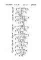
- FIGS. 1A-1Fare top plan views schematically showing the various stations in a butt welding assembly in accordance with this invention.
- FIG. 2is an elevation view partly in section showing the folding step for a tube in accordance with this invention
- FIG. 3is a cross-sectional elevation view showing the aligning step corresponding to FIG. 1B;
- FIG. 4is a cross-sectional elevation view showing the cauterizing step corresponding to step 1C;
- FIG. 5is a perspective view showing the cauterized folded tube moving toward the slitting station.
- FIG. 6is a cross-sectional elevation view showing the tube slitting station corresponding to FIG. 1D.
- FIG. 7is a cross-sectional elevation view showing the heating station corresponding to FIG. 1E.
- FIG. 8is a cross-sectional elevation view showing the butt welding station corresponding to FIG. 1F.
- FIG. 9is a cross-sectional view showing two sets of butt welding tubes as used with a CAPD patient.
- FIGS. 10-16are cross-sectional elevation views showing the sequence of operation in an alternative practice of this invention.
- FIGS. 17-20are cross-sectional elevation views showing the sequence of operations of yet a further alternative practice of this invention.
- FIGS. 1A-1Fshow a butt welding assembly 10 in accordance with this invention.
- a pair of side by side holders 12, 14are mounted on a support 16.
- Support 16is movable back and forth in a horizontal direction through the various stations of the assembly.
- At least one of the holders, such as holder 14,is pivotally mounted so as to be movable toward and away from holder 12.
- Each holder 12, 14also includes a clamp 18, 20 (FIGS. 3-8).
- Clamps 18 and 20are aligned with each other and are preferably contoured to closely clamp the tubes in place of holders 12, 14.
- the details necessary for accomplishing these various movementsmay be of any suitable form known to those skilled in the art and may be based for example upon the structure disclosed in U.S. Pat. Nos. 4,369,779 and 4,610,670 and 4,619,642, the details of which are incorporated herein by reference thereto.
- FIG. 2illustrates the first step in the practice of this invention.
- a tube 22is folded so that the side of one tube portion contacts a side of the other tube portion.
- the foldgenerally takes place along the fold line 23.
- the folding of the tube 22results in cutting communication of the fluid in tube 22 with the folded portion near fold line 23 being free of fluid.
- a pair of such tubes 22is placed in holders 12, 14 and by any suitable clamping device 18, 20 the tubes are mounted to holders 12, 14 until the welding is completed.
- the clamping operationpreferably takes place when support 16 has been moved to the loading station of FIG. 1B.
- FIG. 3 and FIG. 1Bshow the aligning station which includes an alignment bar 24 such as a plate mounted in any suitable manner such as from overhead rail 26 so that support 16 can pass under aligning bar 24.
- holders 12 and 14are laterally movable, holders 12 and 14 are manipulated to move in a lateral direction unitl tubes 22, 22 contact aligning bar 24.
- contoured clamps 18, 20 on holders 12, 14may be opened sufficiently allowing the tubes 22, 22 to be axially moved until the tubes contact aligning bar 24. Clamps 18 and 20 would then be reengaged to firmly mount tubes 22, 22 their respective holders.
- Clamps 18, 20may be of any suitable form such as having complementary grooves associated with grooves in holders 12, 14.
- the clampsmay be closed in any suitable manners such by springs or threaded fasteners.
- FIGS. 1C and 4illustrate the next phase of operation wherein support 16 has moved to the cauterizing station.
- a radiant heater 28 of any suitable constructionis provided to apply heat to the exposed outer surfaces of tubes 22, 22.
- Heater 28likewise is mounted in any suitable manner such as being suspended from rail 26.
- the distance established by aligning bar 24is such that tubes 22, 22 are spaced the proper amount so that heater 28 fits between the tubes and is spaced from the tubes an appropriate distance to apply its radiant heat.
- holders 12, 14may be laterally moved toward or away from each other to accommodate heater 28 being between tubes 22, 22.
- the cauterizing stepresults in the creation of intense radiant heat for a brief period of time which is sufficient to kill any bacteria which may be clinging to the exterior of the tube walls.
- FIG. 5illustrates the next phase of operation wherein support 16 and the tube mounted holders are moved toward the slitting station which includes a cutting instrument 30 such as a knife or blade.
- a cutting instrument 30such as a knife or blade.
- cutter 30is positioned so that it cuts through the near wall of each tube and partially cuts the inner wall along their fold lines 23 to create four sets of individual tube sections 22A and 22D joined by a thin web and tube sections 22B and 22C also joined by their own web.
- the slitting stepis accomplished by a cold tool 30 which may for example be at room temperature. This represents a distinct departure from the prior art practice from using a heated wafer to cut through the tubes.
- tool 30may be mounted in any suitable manner, such as by securement to post 32 suspended from rail 26. When the tubes have been cut along their fold lines the relief of bending stresses in the tubes cause them to open up. If preferred cutting tool 30 may be initially heated to about 500° F. to assure that there is no surviving bacteria on the surface of tool 30.
- the clamped tubesthen move to a tube heating station which includes a further radiant heater 34 mounted in any suitable manner such as being suspended from rail 26.
- Heater 34radiantly heats the exposed tube ends to their welding temperature.
- the next stationis the welding station where the four sets of tube ends 22A-D are pressed into contact with each other. This may be accomplished by any suitable means such as by pivoting holder 14 toward holder 12 as is known in the prior art.
- tube ends 22A and 22Bbecome butt welded as do tube ends 22C and 22D.
- FIG. 9illustrates a particular utility of the invention in connection with CAPD patients.
- a bag 36 of used dialysateincludes tube section 22C which has been folded over to form tube section 22B which in turn is connected to the patient.
- a bag 38 of new dialysateincludes tube section 22A which had been folded over to include tube section 22D.
- Tube section 22Cis sealed at remote stub end 40. The result of the slitting and butt welding operations is such that used bag 36 is then sealed at its end 40 since tube sections 22C and 22D become connected.
- new bag 38becomes in communication with the patient through tube sections 22A and 22B.
- the communication of the various tube sectionsis achieved by applying mechanical stress to the butt welding area so that the tubes become open and are restored to their initial round state.
- the inventionis particularly advantageous in that the desired tubes are welded together in a simple yet efficient manner.
- the stub end 40 of the new bag 38becomes welded to the old bag 36 so that the contents of the old bag 36 are completely sealed.
- a sterile connectionis made between the tube section 22B leading to the patient and the new bag 38.
- a waferis never contaminated with for example, molten PVC so there is no need to replace the wafer or cutting tool 30 between uses and therefore the cutting tool can be in effect permanent.
- By folding the tube in a manner described herein and clamping the tubes in their folded stationno fluid remains in the weld area. Fluids which may easily be damaged (i.e. Blood) are gently removed from the weld area with this process.
- the various cauterization or heating stepsassure the elimination of any bacteria or spores in the weld area.
- a further advantageis that the folded tubes spontaneously open as the cutting tool passes through them because of the bending stresses. This prevents the cold cutting means from dragging bacteria into the lumen of the tubes.
- the resultant welded tubesspontaneously open after removal from the clamps or, if so desired, may require the application of mechanical stress which can be achieved, for example, by a simple finger squeezing action.
- the two sets of welded tubesmay be easily removed from each other by simply removing the tubes away from each other because the flashing between the tubes is sufficiently weak.
- Tool 30may be heated to about 500° F. and then the slitting may take place after tool 30 has cooled to room temperature (about 70° F.) or to an intermediate temperature, such as 320° F.
- FIGS. 10-16show a variation of the invention in which the folding of the tubes takes place about a locator bar.
- FIG. 10illustrates the tube 22 being placed in the clamp base of holder 14.
- plate-like locator bar 25is then placed over tube 22 with its outer edge generally aligned with the outer edge of the base clamp.
- Tube 22is next folded over locator bar 25 (FIG. 12) and clamp top 20 is secured in place (FIG. 13) to flatten tube 22 to the dimension " ⁇ " corresponding to the distance between the clamp base and top.
- FIG. 14illustrates the flattened tube 22 prior to the slitting which is shown in FIG. 15.
- FIG. 15illustrates the flattened tube 22 prior to the slitting which is shown in FIG. 15.
- FIG. 15also illustrates the slitting operation in which the near wall is completely slit but the inner wall is only partially cut leaving a thin web and resulting in the near wall bursting open because of the bending stress.
- FIG. 16shows a second tube between the base clamp of holder 12 and upper clamp 18 with the two tubes butt welded together as previously described.
- locator bar 25is pivotally connected to, for example, its respective clamp base so that it can conveniently swing into position after tube 22 is placed on the clamp base and then pivoted to its inactive position after the welding step.
- FIGS. 17-20illustrate an alternative practice of this invention.
- like reference numeralsare used for like parts.
- the folded tubes 22are mounted in holders 12, 14 and maintained in their folded state by contoured clamps 18, 20, as in the prior arrangement.
- FIG. 17however illustrates the use of a heated wafer 42 which may be of any suitable construction such as one of the forms illustrated and described in application Ser. No. 1955 filed Jan. 9, 1987, the details of which are incorporated herein by reference thereto.
- FIG. 18illustrates the clamped tubes are moved laterally toward each other into contact with wafer 42.
- the radiant heatkills any bacteria on the tube surface.
- the wafer 42 or heating meansis maintained at for example 425° F., contact with this wafer kills any surviving spores on the tube surface.
- FIG. 19illustrates the heated wafer 12 cutting through the tubes with the tubes being heated to their welding temperature.
- the wafer 42is then slid from between the molten tube ends and, as shown in FIG. 20, the tubes are pressed together and butt welded. The tubes are allowed to cool in this state and then removed and re-opened. As a result a weld is created between tube sections 22A and 22B and between tube sections 22C and 22D as previously described.
- the inventionmay be practiced in various manners without departing from the teachings herein.
- the tubesneed not be mounted to side by side jointly movable tube holders. Instead the tubes might be individually moved through their various stations. This practice of the invention however is not as desirable as the preferred practice since it would be more complicated.
- a further alternative practice of the inventionwould be to mount the tubes to holders which remain at a fixed location and to move the various implements (such as heaters, cutter, etc.) to that fixed station in sequence.
- the implementscould be mounted to a movable rail either by being suspended from the rail or mounted on the rail whereupon the holders 12, 14 would have to have a slot therebetween to permit passage of the rail.
- a still further alternative practice of the inventionwould be to sever the folded tips of the tubes using either a cold or hot cutting means. This would not be as desirable as the preferred embodiment since the severed tube tips would get into the mechanism causing possible jam-up of the drive mechanism.
Landscapes
- Engineering & Computer Science (AREA)
- Mechanical Engineering (AREA)
- Health & Medical Sciences (AREA)
- Heart & Thoracic Surgery (AREA)
- Toxicology (AREA)
- Anesthesiology (AREA)
- Electromagnetism (AREA)
- Pulmonology (AREA)
- Physics & Mathematics (AREA)
- Biomedical Technology (AREA)
- Hematology (AREA)
- Life Sciences & Earth Sciences (AREA)
- Animal Behavior & Ethology (AREA)
- General Health & Medical Sciences (AREA)
- Public Health (AREA)
- Veterinary Medicine (AREA)
- External Artificial Organs (AREA)
Abstract
Description
Claims (31)
Priority Applications (1)
| Application Number | Priority Date | Filing Date | Title |
|---|---|---|---|
| US07/017,727US4753697A (en) | 1987-02-24 | 1987-02-24 | Total-containment sterile process and system |
Applications Claiming Priority (1)
| Application Number | Priority Date | Filing Date | Title |
|---|---|---|---|
| US07/017,727US4753697A (en) | 1987-02-24 | 1987-02-24 | Total-containment sterile process and system |
Publications (1)
| Publication Number | Publication Date |
|---|---|
| US4753697Atrue US4753697A (en) | 1988-06-28 |
Family
ID=21784206
Family Applications (1)
| Application Number | Title | Priority Date | Filing Date |
|---|---|---|---|
| US07/017,727Expired - LifetimeUS4753697A (en) | 1987-02-24 | 1987-02-24 | Total-containment sterile process and system |
Country Status (1)
| Country | Link |
|---|---|
| US (1) | US4753697A (en) |
Cited By (59)
| Publication number | Priority date | Publication date | Assignee | Title |
|---|---|---|---|---|
| US4832773A (en)* | 1987-09-22 | 1989-05-23 | Denco, Inc. | Techniques for welding thermoplastic tubes |
| WO1990000970A1 (en)* | 1988-07-28 | 1990-02-08 | Swartz Henry D | Bonding of plastic and plastic matrix composite materials |
| US4933036A (en)* | 1987-09-22 | 1990-06-12 | Denco, Inc. | Techniques for welding thermoplastic tubes |
| US5156701A (en)* | 1990-08-20 | 1992-10-20 | Denco Inc. | Total containment welding of plastic tubes |
| US5158630A (en)* | 1990-08-20 | 1992-10-27 | Denco, Inc. | Total containment welding or plastic tubes |
| WO1993009820A1 (en)* | 1991-11-18 | 1993-05-27 | Gambro Ab | System employing a sterile medical solution containing glucose or glucose-like compounds and a solution intended for said system |
| US5244522A (en)* | 1990-10-29 | 1993-09-14 | Denco Inc. | Total containment welding of plastic tubes |
| US5279685A (en)* | 1990-08-20 | 1994-01-18 | Denco, Inc. | Total containment device for connect/disconnect of plastic tubes |
| EP0515811A3 (en)* | 1991-05-31 | 1994-01-26 | Denco Inc | |
| EP0508474A3 (en)* | 1991-04-10 | 1994-03-23 | Denco Inc | |
| US5439546A (en)* | 1989-05-05 | 1995-08-08 | Brickenstein; Wolf-Jurgen | Process for welding profiles, in particular plastic profiles |
| EP0619175A3 (en)* | 1993-03-11 | 1996-03-13 | Denco Inc | Sterile containment welding device for plastic tubes. |
| EP0662390A3 (en)* | 1993-12-28 | 1996-08-21 | Kureha Chemical Ind Co Ltd | Apparatus and method for welding thermoplastic resin members. |
| US5554253A (en)* | 1993-04-02 | 1996-09-10 | Terumo Kabushiki Kaisha | Tube restoring apparatus and tube restoring method |
| EP0734840A1 (en)* | 1995-03-06 | 1996-10-02 | Denco, Inc. | Total containment welding of plastic tubes |
| EP0778123A3 (en)* | 1995-12-08 | 1998-02-18 | Terumo Kabushiki Kaisha | Tube connecting apparatus |
| US5810398A (en)* | 1992-10-02 | 1998-09-22 | Pall Corporation | Fluid delivery systems and methods and assemblies for making connections |
| US5858016A (en)* | 1992-07-14 | 1999-01-12 | Baxter International Inc. | Sterile/aseptic connector |
| US5868433A (en)* | 1992-10-02 | 1999-02-09 | Pall Corporation | Connector assembly |
| JP3179566B2 (en) | 1991-09-23 | 2001-06-25 | デンコ インコーポレイテッド | Aseptic separation method |
| US6485593B1 (en)* | 1998-10-26 | 2002-11-26 | Kurt J. Christoffersen | Sterile docking apparatus and method of use |
| US20030141009A1 (en)* | 2002-01-31 | 2003-07-31 | Landherr Frank J. | Apparatus and method for connecting and disconnecting flexible tubing |
| US6655655B1 (en) | 1997-05-09 | 2003-12-02 | Pall Corporation | Connector assemblies, fluid systems, and methods for making a connection |
| US20050211373A1 (en)* | 2004-03-29 | 2005-09-29 | Baxter International, Inc. | Method for sterile connection of tubing |
| US20050274673A1 (en)* | 2002-02-01 | 2005-12-15 | Gambro, Inc | Whole blood collection and processing method |
| US20060018989A1 (en)* | 2004-07-22 | 2006-01-26 | Woods Elmer B | Tube sealing device |
| US20060172954A1 (en)* | 2005-01-28 | 2006-08-03 | Jensen Lynn E | Systems and methods for dextrose containing peritoneal dialysis (PD) solutions with neutral pH and reduced glucose degradation product |
| US20070142960A1 (en)* | 2005-12-15 | 2007-06-21 | Bollinger Joseph H | Sterile tubing welder system |
| US7275543B2 (en) | 2002-09-20 | 2007-10-02 | Baxter International Inc. | Coupler member for joining dissimilar materials |
| WO2008016777A2 (en) | 2006-07-31 | 2008-02-07 | Denco, Inc. | Device for welding plastic tubes |
| US20100117310A1 (en)* | 2008-11-07 | 2010-05-13 | Saint-Gobain Performance Plastics Corporation | Large diameter thermoplastic seal |
| US20100116422A1 (en)* | 2008-11-07 | 2010-05-13 | Saint-Gobain Performance Plastics Corporation | Method of forming large diameter thermoplastic seal |
| US8448992B2 (en) | 2011-02-16 | 2013-05-28 | Fenwal, Inc. | Sterile docking device, medical fluid flow system with sterile docking device and method of using same |
| US8454059B2 (en) | 2010-09-13 | 2013-06-04 | Pall Corporation | Connector assemblies, fluid systems including connector assemblies, and procedures for making fluid connections |
| WO2013096038A1 (en) | 2011-12-21 | 2013-06-27 | Fenwal, Inc. | Fluid flow conduits and apparatus and methods for making and joining fluid conduits |
| EP2957402A1 (en) | 2014-06-19 | 2015-12-23 | Fenwal, Inc. | Apparatus and method for opening and/or evaluating connection site |
| US9308709B2 (en) | 2013-06-06 | 2016-04-12 | Fenwal, Inc. | Bonding apparatus and method |
| US9440396B2 (en) | 2014-06-19 | 2016-09-13 | Fenwal, Inc. | Sterile connection device for making multiple connections |
| US9585810B2 (en) | 2010-10-14 | 2017-03-07 | Fresenius Medical Care Holdings, Inc. | Systems and methods for delivery of peritoneal dialysis (PD) solutions with integrated inter-chamber diffuser |
| WO2017048673A1 (en) | 2015-09-14 | 2017-03-23 | Fenwal, Inc. | Apparatus, systems and methods for storing, treating and/or processing blood components |
| EP3216487A1 (en) | 2016-03-07 | 2017-09-13 | Fenwal, Inc. | System and method for creating sterile connections using ultraviolet light |
| US9839582B2 (en) | 2014-12-02 | 2017-12-12 | Fenwal, Inc. | Sterile connection syringe assemblies |
| WO2018071296A1 (en)* | 2016-10-10 | 2018-04-19 | Travi Bruno L | Point of care isothermal diagnostic |
| US10093069B2 (en) | 2012-05-23 | 2018-10-09 | Saint-Gobain Performance Plastics Corporation | Method of forming large diameter thermoplastic seal |
| EP3412334A1 (en) | 2017-06-07 | 2018-12-12 | Fenwal, Inc. | Apparatus and method for mechanically opening a connection site |
| WO2021194824A1 (en) | 2020-03-25 | 2021-09-30 | Fenwal, Inc. | Configurable system to automate blood component manufacturing processes |
| EP3888734A1 (en) | 2020-04-02 | 2021-10-06 | Fenwal, Inc. | Reversible sterile connection system |
| EP4108266A1 (en) | 2021-06-25 | 2022-12-28 | Fenwal, Inc. | Systems and methods for processing whole blood into red blood cell, plasma, and platelet products |
| EP4215226A1 (en) | 2022-01-19 | 2023-07-26 | Fenwal, Inc. | Devices and methods for processing whole blood using flow rate stoppage phase |
| US11731371B2 (en) | 2021-01-25 | 2023-08-22 | Fenwal, Inc. | Sterile connection of tubing |
| EP4233931A1 (en) | 2022-02-28 | 2023-08-30 | Fenwal, Inc. | Systems and methods for inducing plug flow during fluid separation using air |
| EP4371590A2 (en) | 2022-11-15 | 2024-05-22 | Fenwal, Inc. | Maximization of plasma collection and collection of buffy coat or white blood cell layer using collected plasma |
| US20240252803A1 (en)* | 2021-06-02 | 2024-08-01 | Geoffrey L. Hodge | Connection welding for automated sterile connection and fluid transfer |
| EP4442293A1 (en) | 2023-04-07 | 2024-10-09 | Fenwal, Inc. | Platelet collection employing multiple centrifuge rotation rates |
| US12179466B2 (en) | 2020-08-25 | 2024-12-31 | Fenwal, Inc. | System and method for the automated opening of a sterile tubing weld |
| EP4483919A1 (en) | 2023-06-30 | 2025-01-01 | Fenwal, Inc. | System and method for processing of whole blood into plasma products of different categorization |
| EP4506022A1 (en) | 2023-08-11 | 2025-02-12 | Fenwal, Inc. | Method for determining red cell additive solution volume |
| EP4574184A1 (en) | 2023-12-18 | 2025-06-25 | Fenwal, Inc. | Leukoreduction and continuous-flow centrifugation of whole blood |
| US12379916B2 (en) | 2022-03-10 | 2025-08-05 | Terumo Bct, Inc. | Communications and operation control of apheresis systems |
Citations (22)
| Publication number | Priority date | Publication date | Assignee | Title |
|---|---|---|---|---|
| US3013925A (en)* | 1959-04-03 | 1961-12-19 | Phillips Petroleum Co | Method and means for welding thermoplastic pipes |
| US3035631A (en)* | 1961-06-09 | 1962-05-22 | Union Carbide Canada Ltd | Heating tip for welding of plastics |
| US3117903A (en)* | 1960-02-11 | 1964-01-14 | Phillips Petroleum Co | Joining thermoplastic pipe |
| US3769124A (en)* | 1972-03-21 | 1973-10-30 | Mobil Oil Corp | Method and apparatus for splicing foam sheet material |
| US3834971A (en)* | 1972-09-21 | 1974-09-10 | Mobil Oil Corp | Apparatus for butt welding thermoplastics sheets and films |
| US3897296A (en)* | 1973-07-12 | 1975-07-29 | Amchem Prod | Thermal welding of plastic |
| US3968195A (en)* | 1974-06-17 | 1976-07-06 | Marilyn Bishop | Method for making sterile connections |
| US4157723A (en)* | 1977-10-19 | 1979-06-12 | Baxter Travenol Laboratories, Inc. | Method of forming a connection between two sealed conduits using radiant energy |
| US4209013A (en)* | 1979-04-05 | 1980-06-24 | Baxter Travenol Laboratories, Inc. | Sterile connection system using flexible container |
| US4223675A (en)* | 1978-07-24 | 1980-09-23 | Baxter Travenol Laboratories, Inc. | Solution containers such as blood bags and system for preparing same |
| US4242310A (en)* | 1978-11-13 | 1980-12-30 | Baxter Travenol Laboratories, Inc. | Sterile connection apparatus |
| US4253500A (en)* | 1979-07-27 | 1981-03-03 | Baxter Travenol Laboratories, Inc. | Sterile connector adapted for multiple junctions |
| US4369779A (en)* | 1981-02-23 | 1983-01-25 | E. I. Du Pont De Nemours And Company | Sterile docking process, apparatus and system |
| US4405312A (en)* | 1981-08-31 | 1983-09-20 | Abbott Laboratories | Connecting device for medical liquid containers |
| US4412835A (en)* | 1982-07-06 | 1983-11-01 | E. I. Du Pont De Nemours & Company | Sterile docking process, apparatus and system |
| US4443215A (en)* | 1982-07-06 | 1984-04-17 | E. I. Du Pont De Nemours & Company | Sterile docking process, apparatus and system |
| US4475900A (en)* | 1981-06-05 | 1984-10-09 | Popovich Robert P | Method of peritoneal dialysis involving ultraviolet radiation of dialysis apparatus |
| US4507119A (en)* | 1982-07-06 | 1985-03-26 | E. I. Du Pont De Nemours And Company | Sterile docking process, apparatus and system |
| US4516971A (en)* | 1982-07-06 | 1985-05-14 | Spencer Dudley W C | Sterile docking process, apparatus and system |
| US4521263A (en)* | 1982-08-16 | 1985-06-04 | E. I. Du Pont De Nemours And Company | Automatic splicing device and process |
| US4610670A (en)* | 1983-06-13 | 1986-09-09 | E. I. Du Pont De Nemours And Company | Sterile connection process, apparatus and system |
| US4619642A (en)* | 1985-03-12 | 1986-10-28 | E. I. Du Pont De Nemours And Company | Sterile, cold cut connection process, apparatus and system |
- 1987
- 1987-02-24USUS07/017,727patent/US4753697A/ennot_activeExpired - Lifetime
Patent Citations (22)
| Publication number | Priority date | Publication date | Assignee | Title |
|---|---|---|---|---|
| US3013925A (en)* | 1959-04-03 | 1961-12-19 | Phillips Petroleum Co | Method and means for welding thermoplastic pipes |
| US3117903A (en)* | 1960-02-11 | 1964-01-14 | Phillips Petroleum Co | Joining thermoplastic pipe |
| US3035631A (en)* | 1961-06-09 | 1962-05-22 | Union Carbide Canada Ltd | Heating tip for welding of plastics |
| US3769124A (en)* | 1972-03-21 | 1973-10-30 | Mobil Oil Corp | Method and apparatus for splicing foam sheet material |
| US3834971A (en)* | 1972-09-21 | 1974-09-10 | Mobil Oil Corp | Apparatus for butt welding thermoplastics sheets and films |
| US3897296A (en)* | 1973-07-12 | 1975-07-29 | Amchem Prod | Thermal welding of plastic |
| US3968195A (en)* | 1974-06-17 | 1976-07-06 | Marilyn Bishop | Method for making sterile connections |
| US4157723A (en)* | 1977-10-19 | 1979-06-12 | Baxter Travenol Laboratories, Inc. | Method of forming a connection between two sealed conduits using radiant energy |
| US4223675A (en)* | 1978-07-24 | 1980-09-23 | Baxter Travenol Laboratories, Inc. | Solution containers such as blood bags and system for preparing same |
| US4242310A (en)* | 1978-11-13 | 1980-12-30 | Baxter Travenol Laboratories, Inc. | Sterile connection apparatus |
| US4209013A (en)* | 1979-04-05 | 1980-06-24 | Baxter Travenol Laboratories, Inc. | Sterile connection system using flexible container |
| US4253500A (en)* | 1979-07-27 | 1981-03-03 | Baxter Travenol Laboratories, Inc. | Sterile connector adapted for multiple junctions |
| US4369779A (en)* | 1981-02-23 | 1983-01-25 | E. I. Du Pont De Nemours And Company | Sterile docking process, apparatus and system |
| US4475900A (en)* | 1981-06-05 | 1984-10-09 | Popovich Robert P | Method of peritoneal dialysis involving ultraviolet radiation of dialysis apparatus |
| US4405312A (en)* | 1981-08-31 | 1983-09-20 | Abbott Laboratories | Connecting device for medical liquid containers |
| US4412835A (en)* | 1982-07-06 | 1983-11-01 | E. I. Du Pont De Nemours & Company | Sterile docking process, apparatus and system |
| US4443215A (en)* | 1982-07-06 | 1984-04-17 | E. I. Du Pont De Nemours & Company | Sterile docking process, apparatus and system |
| US4507119A (en)* | 1982-07-06 | 1985-03-26 | E. I. Du Pont De Nemours And Company | Sterile docking process, apparatus and system |
| US4516971A (en)* | 1982-07-06 | 1985-05-14 | Spencer Dudley W C | Sterile docking process, apparatus and system |
| US4521263A (en)* | 1982-08-16 | 1985-06-04 | E. I. Du Pont De Nemours And Company | Automatic splicing device and process |
| US4610670A (en)* | 1983-06-13 | 1986-09-09 | E. I. Du Pont De Nemours And Company | Sterile connection process, apparatus and system |
| US4619642A (en)* | 1985-03-12 | 1986-10-28 | E. I. Du Pont De Nemours And Company | Sterile, cold cut connection process, apparatus and system |
Non-Patent Citations (2)
| Title |
|---|
| Transfusion, "An Aseptic Fluid Transfer System for Blood and Blood Components", Sep.-Oct. 1978, pp. 546-552. |
| Transfusion, An Aseptic Fluid Transfer System for Blood and Blood Components , Sep. Oct. 1978, pp. 546 552.* |
Cited By (114)
| Publication number | Priority date | Publication date | Assignee | Title |
|---|---|---|---|---|
| US4933036A (en)* | 1987-09-22 | 1990-06-12 | Denco, Inc. | Techniques for welding thermoplastic tubes |
| US4832773A (en)* | 1987-09-22 | 1989-05-23 | Denco, Inc. | Techniques for welding thermoplastic tubes |
| WO1990000970A1 (en)* | 1988-07-28 | 1990-02-08 | Swartz Henry D | Bonding of plastic and plastic matrix composite materials |
| US5439546A (en)* | 1989-05-05 | 1995-08-08 | Brickenstein; Wolf-Jurgen | Process for welding profiles, in particular plastic profiles |
| US5156701A (en)* | 1990-08-20 | 1992-10-20 | Denco Inc. | Total containment welding of plastic tubes |
| US5158630A (en)* | 1990-08-20 | 1992-10-27 | Denco, Inc. | Total containment welding or plastic tubes |
| US5279685A (en)* | 1990-08-20 | 1994-01-18 | Denco, Inc. | Total containment device for connect/disconnect of plastic tubes |
| JP3009765B2 (en) | 1990-10-29 | 2000-02-14 | デンコ インコーポレイテッド | Whole containment welding equipment |
| US5244522A (en)* | 1990-10-29 | 1993-09-14 | Denco Inc. | Total containment welding of plastic tubes |
| EP0483478A3 (en)* | 1990-10-29 | 1994-01-26 | Denco Inc | |
| EP0508373A3 (en)* | 1991-04-10 | 1994-01-26 | Denco Inc | |
| EP0508474A3 (en)* | 1991-04-10 | 1994-03-23 | Denco Inc | |
| EP1238782A1 (en)* | 1991-04-10 | 2002-09-11 | Denco, Inc. | Total containment welding of plastic tubes |
| JP3320764B2 (en) | 1991-04-10 | 2002-09-03 | デンコ インコーポレイテッド | Nest used for welding plastic tubes |
| EP0515811A3 (en)* | 1991-05-31 | 1994-01-26 | Denco Inc | |
| JP3043895B2 (en) | 1991-05-31 | 2000-05-22 | デンコ インコーポレイテッド | Aseptic welding method for plastic tube section |
| JP3179566B2 (en) | 1991-09-23 | 2001-06-25 | デンコ インコーポレイテッド | Aseptic separation method |
| WO1993009820A1 (en)* | 1991-11-18 | 1993-05-27 | Gambro Ab | System employing a sterile medical solution containing glucose or glucose-like compounds and a solution intended for said system |
| EP0951915A2 (en) | 1991-11-18 | 1999-10-27 | Gambro Lundia AB | System and method for providing a sterile medical solution containing glucose orglucose-like compounds |
| JP3250807B2 (en) | 1991-11-18 | 2002-01-28 | ガンブロ アクチーボラグ | System using sterile medical solution containing glucose or glucose-like compound and solution for the system |
| EP0583582A1 (en)* | 1992-06-26 | 1994-02-23 | Denco, Inc. | Total containment welding of plastic tubes |
| US5858016A (en)* | 1992-07-14 | 1999-01-12 | Baxter International Inc. | Sterile/aseptic connector |
| US5810398A (en)* | 1992-10-02 | 1998-09-22 | Pall Corporation | Fluid delivery systems and methods and assemblies for making connections |
| US5868433A (en)* | 1992-10-02 | 1999-02-09 | Pall Corporation | Connector assembly |
| US6536805B2 (en) | 1992-10-02 | 2003-03-25 | Pall Corporation | Fluid delivery systems and methods and assemblies for making connections |
| US6341802B1 (en) | 1992-10-02 | 2002-01-29 | Pall Corporation | Fluid delivery systems and methods and assemblies for making connections |
| US5674333A (en)* | 1992-10-23 | 1997-10-07 | Denco, Inc. | Total containment welding of plastic tubes |
| EP0619175A3 (en)* | 1993-03-11 | 1996-03-13 | Denco Inc | Sterile containment welding device for plastic tubes. |
| US5554253A (en)* | 1993-04-02 | 1996-09-10 | Terumo Kabushiki Kaisha | Tube restoring apparatus and tube restoring method |
| EP0662390A3 (en)* | 1993-12-28 | 1996-08-21 | Kureha Chemical Ind Co Ltd | Apparatus and method for welding thermoplastic resin members. |
| EP0734840A1 (en)* | 1995-03-06 | 1996-10-02 | Denco, Inc. | Total containment welding of plastic tubes |
| CN1063130C (en)* | 1995-12-08 | 2001-03-14 | 泰尔茂株式会社 | Tube connecting apparatus |
| EP0778123A3 (en)* | 1995-12-08 | 1998-02-18 | Terumo Kabushiki Kaisha | Tube connecting apparatus |
| US5802689A (en)* | 1995-12-08 | 1998-09-08 | Terumo Kabushiki Kaisha | Tube connecting apparatus |
| US6655655B1 (en) | 1997-05-09 | 2003-12-02 | Pall Corporation | Connector assemblies, fluid systems, and methods for making a connection |
| US6485593B1 (en)* | 1998-10-26 | 2002-11-26 | Kurt J. Christoffersen | Sterile docking apparatus and method of use |
| US20030141009A1 (en)* | 2002-01-31 | 2003-07-31 | Landherr Frank J. | Apparatus and method for connecting and disconnecting flexible tubing |
| US20030141634A1 (en)* | 2002-01-31 | 2003-07-31 | Sherwin Shang | Laser weldable flexible medical tubings, films and assemblies thereof |
| US20030143352A1 (en)* | 2002-01-31 | 2003-07-31 | Tahua Yang | Laser weldable flexible medical tubings, films and assemblies thereof |
| US8146642B2 (en) | 2002-01-31 | 2012-04-03 | Baxter International Inc. | Apparatus and method for connecting and disconnecting flexible tubing |
| US6913056B2 (en) | 2002-01-31 | 2005-07-05 | Baxter International Inc. | Apparatus and method for connecting and disconnecting flexible tubing |
| US20090054873A1 (en)* | 2002-01-31 | 2009-02-26 | Baxter International Inc. | Apparatus and method for connecting and disconnecting flexible tubing |
| US7459054B2 (en) | 2002-01-31 | 2008-12-02 | Baxter International Inc. | Apparatus and method for connecting and disconnecting flexible tubing |
| US7226649B2 (en) | 2002-01-31 | 2007-06-05 | Baxter International Inc. | Laser weldable flexible medical tubings, films and assemblies thereof |
| US20050274673A1 (en)* | 2002-02-01 | 2005-12-15 | Gambro, Inc | Whole blood collection and processing method |
| US7275543B2 (en) | 2002-09-20 | 2007-10-02 | Baxter International Inc. | Coupler member for joining dissimilar materials |
| US7722733B2 (en) | 2004-03-29 | 2010-05-25 | Baxter International Inc. | Method for sterile connection of tubing |
| US8162021B2 (en) | 2004-03-29 | 2012-04-24 | Baxter International | Apparatus for sterile connection of tubing |
| US20050211373A1 (en)* | 2004-03-29 | 2005-09-29 | Baxter International, Inc. | Method for sterile connection of tubing |
| US20100224329A1 (en)* | 2004-03-29 | 2010-09-09 | Baxter International Inc. | Apparatus for sterile connection of tubing |
| US20060018989A1 (en)* | 2004-07-22 | 2006-01-26 | Woods Elmer B | Tube sealing device |
| US7285749B2 (en)* | 2004-07-22 | 2007-10-23 | Pdc Facilities, Inc. | Thermoplastic tube sealing device utilizing actuators to control separate heating and cooling stations |
| US20060172954A1 (en)* | 2005-01-28 | 2006-08-03 | Jensen Lynn E | Systems and methods for dextrose containing peritoneal dialysis (PD) solutions with neutral pH and reduced glucose degradation product |
| US7837666B2 (en) | 2005-01-28 | 2010-11-23 | Fresenius Medical Care North America | Systems and methods for delivery of peritoneal dialysis (PD) solutions |
| US20090264854A1 (en)* | 2005-01-28 | 2009-10-22 | Fresenius Medical Care Holdings, Inc. | Systems and Methods for Delivery of Peritoneal Dialysis (PD) Solutions |
| US8328784B2 (en) | 2005-01-28 | 2012-12-11 | Fresenius Medical Care Holdings, Inc. | Systems and methods for delivery of peritoneal dialysis (PD) solutions |
| US9180069B2 (en) | 2005-01-28 | 2015-11-10 | Fresenius Medical Care Holdings, Inc. | Systems and methods for delivery of peritoneal dialysis (PD) solutions |
| US20080027374A1 (en)* | 2005-01-28 | 2008-01-31 | Fresenius Medical Care Holdings, Inc. | Systems and methods for delivery of peritoneal dialysis (pd) solutions |
| US20060186045A1 (en)* | 2005-01-28 | 2006-08-24 | Fresenius Medical Care North America | Systems and methods for delivery of peritoneal dialysis (PD) solutions |
| US20090078592A1 (en)* | 2005-01-28 | 2009-03-26 | Fresenius Medical Care North America | Systems and methods for delivery of peritoneal dialysis (pd) solutions |
| US7935070B2 (en) | 2005-01-28 | 2011-05-03 | Fresenius Medical Care North America | Systems and methods for dextrose containing peritoneal dialysis (PD) solutions with neutral pH and reduced glucose degradation product |
| US7985212B2 (en) | 2005-01-28 | 2011-07-26 | Fresenius Medical Care Holdings, Inc. | Systems and methods for delivery of peritoneal dialysis (PD) solutions |
| US8052631B2 (en) | 2005-01-28 | 2011-11-08 | Fresenius Medical Care Holdings, Inc. | Systems and methods for delivery of peritoneal dialysis (PD) solutions |
| US20070142960A1 (en)* | 2005-12-15 | 2007-06-21 | Bollinger Joseph H | Sterile tubing welder system |
| WO2008016777A2 (en) | 2006-07-31 | 2008-02-07 | Denco, Inc. | Device for welding plastic tubes |
| EP2774747A1 (en)* | 2006-07-31 | 2014-09-10 | Genesis Bps, Llc | Device for welding plastic tubes |
| EP2046560A4 (en)* | 2006-07-31 | 2013-05-01 | Genesis Bps Llc | Device for welding plastic tubes |
| US20100117310A1 (en)* | 2008-11-07 | 2010-05-13 | Saint-Gobain Performance Plastics Corporation | Large diameter thermoplastic seal |
| US8721823B2 (en) | 2008-11-07 | 2014-05-13 | Saint-Gobain Performance Plastics Corporation | Method of forming large diameter thermoplastic seal |
| US9702462B2 (en) | 2008-11-07 | 2017-07-11 | Saint-Gobain Performance Plastics Corporation | Large diameter thermoplastic seal |
| US20100116422A1 (en)* | 2008-11-07 | 2010-05-13 | Saint-Gobain Performance Plastics Corporation | Method of forming large diameter thermoplastic seal |
| US8454059B2 (en) | 2010-09-13 | 2013-06-04 | Pall Corporation | Connector assemblies, fluid systems including connector assemblies, and procedures for making fluid connections |
| US9585810B2 (en) | 2010-10-14 | 2017-03-07 | Fresenius Medical Care Holdings, Inc. | Systems and methods for delivery of peritoneal dialysis (PD) solutions with integrated inter-chamber diffuser |
| US10842714B2 (en) | 2010-10-14 | 2020-11-24 | Fresenius Medical Care Holdings, Inc. | Systems and methods for delivery of peritoneal dialysis (PD) solutions with integrated inter chamber diffuser |
| US11779519B2 (en) | 2010-10-14 | 2023-10-10 | Fresenius Medical Care Holdings, Inc. | Systems and methods for delivery of peritoneal dialysis (PD) solutions with integrated inter-chamber diffuser |
| US8448992B2 (en) | 2011-02-16 | 2013-05-28 | Fenwal, Inc. | Sterile docking device, medical fluid flow system with sterile docking device and method of using same |
| US9199070B2 (en) | 2011-12-21 | 2015-12-01 | Fenwal, Inc. | Fluid flow conduits and apparatus and methods for making and joining fluid conduits |
| US10307582B2 (en) | 2011-12-21 | 2019-06-04 | Fenwal, Inc. | Fluid flow conduits and apparatus and methods for making and joining fluid conduits |
| EP2722070A1 (en) | 2011-12-21 | 2014-04-23 | Fenwal, Inc. | Fluid flow conduits |
| WO2013096038A1 (en) | 2011-12-21 | 2013-06-27 | Fenwal, Inc. | Fluid flow conduits and apparatus and methods for making and joining fluid conduits |
| US10093069B2 (en) | 2012-05-23 | 2018-10-09 | Saint-Gobain Performance Plastics Corporation | Method of forming large diameter thermoplastic seal |
| US9308709B2 (en) | 2013-06-06 | 2016-04-12 | Fenwal, Inc. | Bonding apparatus and method |
| US9440396B2 (en) | 2014-06-19 | 2016-09-13 | Fenwal, Inc. | Sterile connection device for making multiple connections |
| EP2957402A1 (en) | 2014-06-19 | 2015-12-23 | Fenwal, Inc. | Apparatus and method for opening and/or evaluating connection site |
| EP3219462A1 (en) | 2014-06-19 | 2017-09-20 | Fenwal, Inc. | Apparatus and method for connecting and evaluating a connection site |
| US9839582B2 (en) | 2014-12-02 | 2017-12-12 | Fenwal, Inc. | Sterile connection syringe assemblies |
| WO2017048673A1 (en) | 2015-09-14 | 2017-03-23 | Fenwal, Inc. | Apparatus, systems and methods for storing, treating and/or processing blood components |
| EP3434296A3 (en)* | 2015-09-14 | 2019-05-01 | Fenwal, Inc. | Apparatus, systems and methods for storing, treating and/or processing blood components |
| US10730058B2 (en) | 2015-09-14 | 2020-08-04 | Fenwal, Inc. | Apparatus, systems and methods for storing, treating and/or processing blood and blood components |
| EP3434296A2 (en) | 2015-09-14 | 2019-01-30 | Fenwal, Inc. | Apparatus, systems and methods for storing, treating and/or processing blood components |
| US12179220B2 (en) | 2015-09-14 | 2024-12-31 | Fenwal, Inc. | Apparatus, systems and methods for storing, treating and/or processing blood and blood components |
| US11247216B2 (en) | 2015-09-14 | 2022-02-15 | Fenwal, Inc. | Methods for sterilely connecting a container to a blood processing set |
| EP4477322A2 (en) | 2015-09-14 | 2024-12-18 | Fenwal, Inc. | Apparatus, systems and methods for storing, treating and/or processing blood components |
| US12121915B2 (en) | 2015-09-14 | 2024-10-22 | Fenwal, Inc. | Systems for storing, treating and/or processing blood and blood components |
| EP3216487A1 (en) | 2016-03-07 | 2017-09-13 | Fenwal, Inc. | System and method for creating sterile connections using ultraviolet light |
| WO2018071296A1 (en)* | 2016-10-10 | 2018-04-19 | Travi Bruno L | Point of care isothermal diagnostic |
| EP3412334A1 (en) | 2017-06-07 | 2018-12-12 | Fenwal, Inc. | Apparatus and method for mechanically opening a connection site |
| US10919235B2 (en) | 2017-06-07 | 2021-02-16 | Fenwal, Inc. | Apparatus and method for mechanically opening a connection site |
| US11325321B2 (en) | 2017-06-07 | 2022-05-10 | Fenwal, Inc. | Apparatus and method for mechanically opening a connection site |
| WO2021194824A1 (en) | 2020-03-25 | 2021-09-30 | Fenwal, Inc. | Configurable system to automate blood component manufacturing processes |
| US12280231B2 (en) | 2020-04-02 | 2025-04-22 | Fenwal, Inc. | Reversible sterile connection system |
| EP3888734A1 (en) | 2020-04-02 | 2021-10-06 | Fenwal, Inc. | Reversible sterile connection system |
| US12179466B2 (en) | 2020-08-25 | 2024-12-31 | Fenwal, Inc. | System and method for the automated opening of a sterile tubing weld |
| US11731371B2 (en) | 2021-01-25 | 2023-08-22 | Fenwal, Inc. | Sterile connection of tubing |
| US20240252803A1 (en)* | 2021-06-02 | 2024-08-01 | Geoffrey L. Hodge | Connection welding for automated sterile connection and fluid transfer |
| EP4108266A1 (en) | 2021-06-25 | 2022-12-28 | Fenwal, Inc. | Systems and methods for processing whole blood into red blood cell, plasma, and platelet products |
| EP4215226A1 (en) | 2022-01-19 | 2023-07-26 | Fenwal, Inc. | Devices and methods for processing whole blood using flow rate stoppage phase |
| EP4233931A1 (en) | 2022-02-28 | 2023-08-30 | Fenwal, Inc. | Systems and methods for inducing plug flow during fluid separation using air |
| US12379916B2 (en) | 2022-03-10 | 2025-08-05 | Terumo Bct, Inc. | Communications and operation control of apheresis systems |
| EP4371590A2 (en) | 2022-11-15 | 2024-05-22 | Fenwal, Inc. | Maximization of plasma collection and collection of buffy coat or white blood cell layer using collected plasma |
| EP4442293A1 (en) | 2023-04-07 | 2024-10-09 | Fenwal, Inc. | Platelet collection employing multiple centrifuge rotation rates |
| EP4483919A1 (en) | 2023-06-30 | 2025-01-01 | Fenwal, Inc. | System and method for processing of whole blood into plasma products of different categorization |
| EP4506022A1 (en) | 2023-08-11 | 2025-02-12 | Fenwal, Inc. | Method for determining red cell additive solution volume |
| EP4574184A1 (en) | 2023-12-18 | 2025-06-25 | Fenwal, Inc. | Leukoreduction and continuous-flow centrifugation of whole blood |
Similar Documents
| Publication | Publication Date | Title |
|---|---|---|
| US4753697A (en) | Total-containment sterile process and system | |
| US4507119A (en) | Sterile docking process, apparatus and system | |
| US4443215A (en) | Sterile docking process, apparatus and system | |
| US4412835A (en) | Sterile docking process, apparatus and system | |
| US4619642A (en) | Sterile, cold cut connection process, apparatus and system | |
| US4610670A (en) | Sterile connection process, apparatus and system | |
| US4516971A (en) | Sterile docking process, apparatus and system | |
| US4369779A (en) | Sterile docking process, apparatus and system | |
| EP0044204B1 (en) | Sterile docking process, apparatus and system | |
| EP2731667B1 (en) | Method of joining fluid flow circuits | |
| US3051164A (en) | Jacket isolator for use in sterile techniques | |
| CA1178505A (en) | Spike exchanger for continuous ambulatory peritoneal dialysis | |
| CA2043456A1 (en) | Sterile entry/exit total containment process for closed systems using plastic tubes | |
| CN114789561B (en) | Sterile connection of tubing | |
| JPS6130582B2 (en) | ||
| JPH0227936B2 (en) | ||
| CA1210912A (en) | Sterile docking process, apparatus and system | |
| CA1210914A (en) | Sterile docking process, apparatus and system | |
| JPH0623041A (en) | Piping dosing set used for peritoneal dialysis | |
| Hamilton et al. | The sterile weld: a new method for connection in continuous ambulatory peritoneal dialysis | |
| JPH05269202A (en) | Peritoneal dialyzer and dialyzate storage container for peritoneal dialysis | |
| WO1984002383A1 (en) | A multiple access fluid transfer device and its method of manufacture |
Legal Events
| Date | Code | Title | Description |
|---|---|---|---|
| AS | Assignment | Owner name:DENCO, INC., 501 SILVERSIDE ROAD, SUITE 36, WILMIN Free format text:ASSIGNMENT OF ASSIGNORS INTEREST.;ASSIGNORS:SHAPOSKA, JOHN B.;SPENCER, DUDLEY W. C.;REEL/FRAME:004847/0859 Effective date:19870217 Owner name:DENCO, INC.,DELAWARE Free format text:ASSIGNMENT OF ASSIGNORS INTEREST;ASSIGNORS:SHAPOSKA, JOHN B.;SPENCER, DUDLEY W. C.;REEL/FRAME:004847/0859 Effective date:19870217 | |
| STCF | Information on status: patent grant | Free format text:PATENTED CASE | |
| FPAY | Fee payment | Year of fee payment:4 | |
| FEPP | Fee payment procedure | Free format text:PAT HLDR NO LONGER CLAIMS SMALL ENT STAT AS INDIV INVENTOR (ORIGINAL EVENT CODE: LSM1); ENTITY STATUS OF PATENT OWNER: LARGE ENTITY | |
| FPAY | Fee payment | Year of fee payment:8 | |
| FPAY | Fee payment | Year of fee payment:12 | |
| AS | Assignment | Owner name:GENESIS BPS, LLC, NEW JERSEY Free format text:ASSIGNMENT OF ASSIGNORS INTEREST;ASSIGNOR:DENCO, INC.;REEL/FRAME:025517/0820 Effective date:20101015 |