US4752511A - Method and apparatus for sealing the space between pipes and linings therefor - Google Patents
Method and apparatus for sealing the space between pipes and linings thereforDownload PDFInfo
- Publication number
- US4752511A US4752511AUS06/896,715US89671586AUS4752511AUS 4752511 AUS4752511 AUS 4752511AUS 89671586 AUS89671586 AUS 89671586AUS 4752511 AUS4752511 AUS 4752511A
- Authority
- US
- United States
- Prior art keywords
- pipe
- lining
- length
- ring
- liner
- Prior art date
- Legal status (The legal status is an assumption and is not a legal conclusion. Google has not performed a legal analysis and makes no representation as to the accuracy of the status listed.)
- Expired - Lifetime
Links
Images

Classifications
- F—MECHANICAL ENGINEERING; LIGHTING; HEATING; WEAPONS; BLASTING
- F16—ENGINEERING ELEMENTS AND UNITS; GENERAL MEASURES FOR PRODUCING AND MAINTAINING EFFECTIVE FUNCTIONING OF MACHINES OR INSTALLATIONS; THERMAL INSULATION IN GENERAL
- F16L—PIPES; JOINTS OR FITTINGS FOR PIPES; SUPPORTS FOR PIPES, CABLES OR PROTECTIVE TUBING; MEANS FOR THERMAL INSULATION IN GENERAL
- F16L55/00—Devices or appurtenances for use in, or in connection with, pipes or pipe systems
- F16L55/16—Devices for covering leaks in pipes or hoses, e.g. hose-menders
- F16L55/162—Devices for covering leaks in pipes or hoses, e.g. hose-menders from inside the pipe
- F16L55/165—Devices for covering leaks in pipes or hoses, e.g. hose-menders from inside the pipe a pipe or flexible liner being inserted in the damaged section
- Y—GENERAL TAGGING OF NEW TECHNOLOGICAL DEVELOPMENTS; GENERAL TAGGING OF CROSS-SECTIONAL TECHNOLOGIES SPANNING OVER SEVERAL SECTIONS OF THE IPC; TECHNICAL SUBJECTS COVERED BY FORMER USPC CROSS-REFERENCE ART COLLECTIONS [XRACs] AND DIGESTS
- Y10—TECHNICAL SUBJECTS COVERED BY FORMER USPC
- Y10T—TECHNICAL SUBJECTS COVERED BY FORMER US CLASSIFICATION
- Y10T428/00—Stock material or miscellaneous articles
- Y10T428/13—Hollow or container type article [e.g., tube, vase, etc.]
- Y10T428/1352—Polymer or resin containing [i.e., natural or synthetic]
- Y10T428/1355—Elemental metal containing [e.g., substrate, foil, film, coating, etc.]
- Y10T428/1359—Three or more layers [continuous layer]
- Y—GENERAL TAGGING OF NEW TECHNOLOGICAL DEVELOPMENTS; GENERAL TAGGING OF CROSS-SECTIONAL TECHNOLOGIES SPANNING OVER SEVERAL SECTIONS OF THE IPC; TECHNICAL SUBJECTS COVERED BY FORMER USPC CROSS-REFERENCE ART COLLECTIONS [XRACs] AND DIGESTS
- Y10—TECHNICAL SUBJECTS COVERED BY FORMER USPC
- Y10T—TECHNICAL SUBJECTS COVERED BY FORMER US CLASSIFICATION
- Y10T428/00—Stock material or miscellaneous articles
- Y10T428/13—Hollow or container type article [e.g., tube, vase, etc.]
- Y10T428/1352—Polymer or resin containing [i.e., natural or synthetic]
- Y10T428/1362—Textile, fabric, cloth, or pile containing [e.g., web, net, woven, knitted, mesh, nonwoven, matted, etc.]
- Y—GENERAL TAGGING OF NEW TECHNOLOGICAL DEVELOPMENTS; GENERAL TAGGING OF CROSS-SECTIONAL TECHNOLOGIES SPANNING OVER SEVERAL SECTIONS OF THE IPC; TECHNICAL SUBJECTS COVERED BY FORMER USPC CROSS-REFERENCE ART COLLECTIONS [XRACs] AND DIGESTS
- Y10—TECHNICAL SUBJECTS COVERED BY FORMER USPC
- Y10T—TECHNICAL SUBJECTS COVERED BY FORMER US CLASSIFICATION
- Y10T428/00—Stock material or miscellaneous articles
- Y10T428/13—Hollow or container type article [e.g., tube, vase, etc.]
- Y10T428/1352—Polymer or resin containing [i.e., natural or synthetic]
- Y10T428/139—Open-ended, self-supporting conduit, cylinder, or tube-type article
- Y10T428/1393—Multilayer [continuous layer]
Definitions
- the present inventionrelates to method and apparatus for preventing escape or travel of fluid along spaces that may form between a pipe and a lining that is applied to the interior of the pipe.
- Pipelines and passagewaysneed repair or replacement as they age. Replacement, particularly of underground pipelines and passageways, is extremely costly. Accordingly it is becoming increasingly common to provide linings for such pipelines and passageways while those structures remain in place.
- Various types of lininghave been provided, some flexible and some rigid and some flexible when applied but rigidifying after application, but in all cases it is preferable that the lining be of a nature such that it closely conforms to and engages the inner surface of the pipeline or passageway.
- the term "pipe”is here used generically to include all types of pipelines or passageways) is accomplished by internally pressurizing the lining.
- flexible lining tubesare utilized. These tubes comprise a resin-absorbent material which serves to soak up a curable synthetic resin.
- the resin-impregnated tubeinitially flexible, is inserted into the pipe and then forced radially outwardly into engagement with the internal pipe surface by internally pressurizing the flexible tube by means of pneumatic or hydraulic pressure, with or without providing a vacuum in the initial space between the tube and the pipe. After that internal pressurization, the resin with which the tube is impregnated cures, thus producing a rigid lining within the pipe which ideally closely conforms to the entire inner surface of the pipe.
- the liningafter the internal pressure is relieved, can shrink away from the pipe, creating a small annular gap, perhaps only a few millimeters wide in a pipe having a one meter diameter, that gap sometimes occurring over all or a substantial portion of the length of the lined pipe.
- This annular gapdoes not cause concern in pipes such as sewer pipes where the fluid passing through the pipe is a liquid and is at relatively low pressure, but in the case of a pressure pipe, such as a gas pipeline, the annular gap, when it forms, constitutes a serious problem in that the gas can gain access to and then travel along the axial length of that gap and escape, thus rendering the lining to a large extent ineffective.
- sealing ringsare located at spaced intervals along the length of the pipe, either prior to or during the application of the lining to the pipe.
- the ringscomprise a resiliently deformable material so that they will compress when an initially flexible lining is used and when that lining is pressed against the inner surface of the pipe and will recover incompletely in the event of shrinkage of the lining away from the pipe, thereby to maintain a circumferential seal between the pipe and the lining, the circumferential seals produced by the plurality of axially spaced sealing rings thus preventing fluid from moving axially along the length of the pipe for any distance greater than the axial spacing between the sealing rings. Hence any fluid which enters a given annular gap will be trapped there and cannot escape.
- the sealing ringswhich may be of a rubbery elastomeric material, are designed so that they will be compressed, when the lining is initially applied, by an amount greater than the amount which they will recover during the expected shrinkage of the lining.
- the ringsmay take any suitable cross-section, such as circular, and may be provided with sealing ribs to form a labyrinth seal which will deform more than the main body of the ring.
- the present inventionrelates to method and apparatus for providing seals between a pipe and a pipe lining as defined in the appended claims and as described in this specification, taken together with the accompanying drawings, in which:
- FIG. 1is a diagrammatic cross-sectional view illustrating the principle of the pipe lining disclosed in U.S. Pat. No. 4,064,211, utilizing a flexible lining which is pressed into engagement with the pipe inner surface and cured, typical sealing rings being shown in position within the pipe prior to the insertion of the lining;
- FIG. 2is a cross-sectional view showing the flexible lining tube which is used in the method illustrated in FIG. 1;
- FIG. 3is a cross-sectional view illustrating the relationship between the lining, the pipe inner surface and a sealing ring before internal pressure is applied to the lining;
- FIG. 3Ais a view similar to FIG. 3 but showing the relationship of the parts after pressure has been applied inside the lining so as to force the lining against the inner surface of the pipe;
- FIG. 4is a view similar to FIG. 3A but showing the relationship of the parts after the lining has solidified and has shrunk slightly away from the pipe inner surface;
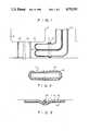
- FIGS. 5, 6 and 7are cross-sectional views of alternative sealing rings
- FIG. 8is a view similar to FIG. 2 but with respect to a lining into which the sealing rings are incorporated before the lining is applied;
- FIG. 9is a diagrammatic side elevational view of a length of the lining of FIG. 7.
- FIG. 1discloses diagrammatically how a lining, generally designated 10, is applied to an underground pipeline 12 between two manholes 14 and 16.
- the lining 10is in the form of a tube formed of a flexible material of the construction shown basically in FIG. 2 comprising, prior to insertion in the pipeline 12, an inner felt or other resin-absorbent material 18 surrounded by a fluid-impermeable membrane 20 normally bonded to the felt layer 18 and usually constituted by a synthetic plastic film.
- the felt layer 18is impregnated with a suitable curable synthetic resin which makes the lining of considerable weight while still flexible.
- a leading end 11 of the lining 10is inserted through a feed elbow 22 and the leading end 11 is turned back upon itself and fixed to the lower end of the feed elbow, as at 13.
- Water or other fluidis then forced into the feed elbow 22 which causes the lining tube 10 to evert into and along the interior of the pipe 12.
- the resin-impregnated felt layer 18becomes the outer layer while the fluid-impermeable layer 20 becomes the inner layer.
- the fluid which everts the lining tube 10also exerts a radial pressure on the interior of the lining, expanding it and pressing it against the inner surface of the pipe 12.
- the liningis maintained in engagement with the pipe 12 until the resin which impregnates the felt layer 18 cures.
- That curingmay be effected by any suitable means, such as through the use of heated water, induction heating, or high frequency ultrasonics.
- the fluidis removed from inside the lining 10, thus leaving a hard, rigid lining applied to the pipeline surface.
- sealing ringsgenerally designated 26, between the lining 10 and the pipe 12, those rings 26 being spaced at intervals along the length of the pipe.
- sealing ringsThere is nothing particularly critical about the axial spacing between adjacent sealing rings 26, and that spacing will vary widely from installation to installation, depending upon the nature of the fluid carried by the pipe, the condition of the pipe, the distance between manholes or other transverse connections when the pipe is underground, the degree to which the fluid can be expected to penetrate the lining, and the like.
- theywill be located on opposite sides of joints in the pipe connecting the pipe, for example, with branch pipes, because such joints are particularly susceptible to fluid leakage therethrough.
- FIGS. 3, 3A and 4One typical sealing ring 26 is shown in FIGS. 3, 3A and 4. It comprises a ring of resilient material of circular cross-section. Natural or synthetic rubber or comparable plastics are suitable for use, with the particular material employed being selected in the light of the conditions to which it will be subjected and the substances to which it will be exposed in use.
- the sealing ringsare placed in position inside the pipe 12 prior to the insertion and cure of the lining 10.
- the sealing ring 26will be interposed between the felt layer 18 and the pipe 12, and as pressure is applied inside the lining 10 to force it against the inner surface of the pipe the sealing ring 26 will, as diagrammatically illustrated in FIG. 3A, become compressed to a substantial degree.
- FIG. 4diagrammatically indicates the relationship of the parts.
- the shrinkage of the lining 10 from the pipe 12has produced an annular gap 28 between the lining 10 and the pipe 12, and the sealing ring 26 will have expanded somewhat from its extremely compressed condition shown in FIG. 3A, but the ring 26 will still be compressed compared to its normal condition shown in FIG. 3.
- each sealing ring 26provides a circumferential seal between the lining 10 and the pipe 12, so that any fluid which may make its way into a given annular gap 28 cannot travel along the length of the pipe 12, but will be confined between a pair of adjacent sealing rings 26.
- FIGS. 5 and 6illustrate typical alternative cross-sectional shapes for sealing rings 26a and 26b respectively.
- the ring 26ahas ribs 30 which may preferably define a labyrinth over the radially inner surface of the ring.
- the ring 26bhas a pre-flattened section 32 which provides a wide sealing surface engagement. Where even wider lining-pipe sealing surfaces are desired, and as illustrated in FIG.
- the sealing ring 26may be defined by two adjacent ring elements 26c and 26d spaced from one another by a small distance, for example one-half inch, with the space between them being filled by a grout or other mastic material 26e, so that when the sealing ring assembly 26 is pressed against the inner surface of the pipe the ring elements 26c and 26d will compress until the grout or other mastic material 26e firmly engages the inner surface of the pipe, thus producing a sealing engagement over a greater area than is feasible with a single sealing ring 26.
- sealing rings 26may be positioned within the pipe 12 before the lining 10 is inserted.
- the sealing rings 26may be made a part of the lining tube 10 before that tube is inserted, the sealing rings 26 then moving into position along the length of the pipe 12 as the tube 10 is inserted. To that end the rings 26 may be adhesively secured to the original inner tube surface of the impregnated felt layer 18, as illustrated in FIGS. 7 and 8.
Landscapes
- Engineering & Computer Science (AREA)
- General Engineering & Computer Science (AREA)
- Mechanical Engineering (AREA)
- Lining Or Joining Of Plastics Or The Like (AREA)
- Pipe Accessories (AREA)
Abstract
Description
Claims (13)
Priority Applications (6)
| Application Number | Priority Date | Filing Date | Title |
|---|---|---|---|
| US06/896,715US4752511A (en) | 1986-08-15 | 1986-08-15 | Method and apparatus for sealing the space between pipes and linings therefor |
| EP86112528AEP0217189B1 (en) | 1985-09-17 | 1986-09-10 | lining and method of a lining pipe |
| DE8686112528TDE3667843D1 (en) | 1985-09-17 | 1986-09-10 | PIPE WITH LINING, LINING AND METHOD FOR LINING A PIPE. |
| AT86112528TATE49045T1 (en) | 1985-09-17 | 1986-09-10 | PIPE WITH LINER, LINING AND METHOD OF LINING A PIPE. |
| JP61217378AJPH0753417B2 (en) | 1985-09-17 | 1986-09-17 | Pipe structure, pipe lining and pipe lining method |
| HK8192AHK8192A (en) | 1985-09-17 | 1992-01-23 | Lined pipe,lining and method of a lining pipe |
Applications Claiming Priority (1)
| Application Number | Priority Date | Filing Date | Title |
|---|---|---|---|
| US06/896,715US4752511A (en) | 1986-08-15 | 1986-08-15 | Method and apparatus for sealing the space between pipes and linings therefor |
Publications (1)
| Publication Number | Publication Date |
|---|---|
| US4752511Atrue US4752511A (en) | 1988-06-21 |
Family
ID=25406711
Family Applications (1)
| Application Number | Title | Priority Date | Filing Date |
|---|---|---|---|
| US06/896,715Expired - LifetimeUS4752511A (en) | 1985-09-17 | 1986-08-15 | Method and apparatus for sealing the space between pipes and linings therefor |
Country Status (1)
| Country | Link |
|---|---|
| US (1) | US4752511A (en) |
Cited By (36)
| Publication number | Priority date | Publication date | Assignee | Title |
|---|---|---|---|---|
| US4865673A (en)* | 1986-02-20 | 1989-09-12 | Inzhenerny Tsentr "Truboprovod" | Method of applying a protective coating to the inner surface of a pipeline and device for carrying out the method |
| US4901424A (en)* | 1988-07-26 | 1990-02-20 | Insituform Of North America, Inc. | Method of forming an end seal for a pipe liner |
| US4956041A (en)* | 1987-12-28 | 1990-09-11 | Osaka Bousui Construction Co., Ltd. | Method of lining branch pipe portion of underground main pipe with rigid plastics tube |
| US5044405A (en)* | 1989-08-21 | 1991-09-03 | Insituform Licensees B.V. | Method and apparatus for repair-lining of short sections of pipe |
| US5223189A (en)* | 1992-01-07 | 1993-06-29 | Gundle Lining Systems, Inc. | Method of sealing lateral connections for pipe liners |
| US5329063A (en)* | 1991-05-31 | 1994-07-12 | Get, Inc. | Liner assembly for lining branch pipes and a method for manufacturing the liner assembly |
| US5384086A (en)* | 1990-01-18 | 1995-01-24 | Insituform (Netherlands) Bv | Lining of pipelines or passageways |
| US5388616A (en)* | 1993-05-19 | 1995-02-14 | Mueller; Hans | Invertible liner for internal surfaces of fluid conveying pipes and the like |
| US5439033A (en)* | 1993-09-28 | 1995-08-08 | Shonan Gosei-Jushi Seisakusho K.K. | Method of lining a branch pipe |
| US5451351A (en)* | 1991-09-13 | 1995-09-19 | Composite Components, Inc. | Method for rehabilitating a pipe with a liner having an electrically conductive layer |
| US5546992A (en)* | 1994-01-18 | 1996-08-20 | Insituform (Netherlands) B.V. | Dual containment pipe rehabilitation system |
| US5566719A (en)* | 1994-07-05 | 1996-10-22 | Shonan Gosei-Jushi Seisakusho K.K. | Method for lining a branch pipe of an underground pipe |
| US5653555A (en) | 1995-05-19 | 1997-08-05 | Inliner, U.S.A. | Multiple resin system for rehabilitating pipe |
| US5699838A (en) | 1995-05-22 | 1997-12-23 | Inliner, U.S.A. | Apparatus for vacuum impregnation of a flexible, hollow tube |
| US5765597A (en)* | 1994-08-19 | 1998-06-16 | Kiest, Jr.; Larry W. | Apparatus for repairing a pipeline and method for using same |
| US5794663A (en)* | 1994-08-19 | 1998-08-18 | Lmk Enterprises | Apparatus for repairing a pipeline and method for using same |
| US5816293A (en)* | 1996-03-27 | 1998-10-06 | Kiest, Jr.; Larry W. | Apparatus for installation of a liner within a pipeline |
| US5925409A (en)* | 1997-08-27 | 1999-07-20 | Reichhold, Inc. | Resins for lining surfaces |
| US5950682A (en)* | 1994-08-19 | 1999-09-14 | Lmk Enterprises, Inc. | Apparatus and method for repairing the junction of a sewer main line and lateral |
| US5964249A (en)* | 1996-03-27 | 1999-10-12 | Lmk Enterprises, Inc. | Apparatus and method for repairing a pipeline |
| US5971029A (en)* | 1995-07-11 | 1999-10-26 | Instituform (Netherlands) B.V. | Dual containment pipe system and method of installation |
| US6053211A (en)* | 1998-09-11 | 2000-04-25 | Karl Weiss Hoch- Tief- Und Rohrleitungsbau Gmbh & Co. | Method for the coating of sewer pipes including apparatus for carrying out the method |
| US6170531B1 (en)* | 1997-05-02 | 2001-01-09 | Karl Otto Braun Kg | Flexible tubular lining material |
| US6423258B1 (en) | 2000-07-31 | 2002-07-23 | American Pipe & Plastics, Inc. | Machine and method for providing folded pipe liners |
| US20030038403A1 (en)* | 2001-08-21 | 2003-02-27 | American Pipe & Plastics, Inc. | Machine and method for providing folded pipe liners |
| US20030212510A1 (en)* | 2002-05-13 | 2003-11-13 | Gee Gregory P. | Optimized convection based mass airflow sensor circuit |
| US6692802B1 (en) | 1997-08-27 | 2004-02-17 | Reichhold, Inc. | Resins for lining surfaces |
| WO2006071823A1 (en) | 2004-12-27 | 2006-07-06 | Proline Technologies, N.A., Llc | Method, apparatus and system for lining conduits |
| US7096890B2 (en) | 2002-06-19 | 2006-08-29 | Saint-Gobain Technical Fabrics Canada, Ltd. | Inversion liner and liner components for conduits |
| US20060197262A1 (en)* | 2005-03-04 | 2006-09-07 | Waring Stephen T | Liner installation in pipes |
| US20080236692A1 (en)* | 2007-03-30 | 2008-10-02 | Lmk Enterprises, Inc. | Bladderless pipeliner and method for using same |
| US7478650B2 (en) | 2002-06-19 | 2009-01-20 | Saint-Gobain Technical Fabrics Canada, Ltd. | Inversion liner and liner components for conduits |
| US9366375B2 (en) | 2007-08-27 | 2016-06-14 | Lmk Technologies, Llc | Device and method for repairing pipe |
| US9851041B2 (en) | 2015-03-04 | 2017-12-26 | Emagineered Solutions, Inc. | Tubing everting apparatus, assemblies, and methods |
| EP3324092A1 (en)* | 2016-11-18 | 2018-05-23 | Railcare Group AB | Reinforced tube and method of relining a culvert with such a tube |
| US11566742B2 (en) | 2017-08-18 | 2023-01-31 | Moray Group, Llc | Method, apparatus and system for lining conduits |
Citations (4)
| Publication number | Priority date | Publication date | Assignee | Title |
|---|---|---|---|---|
| US4064211A (en)* | 1972-12-08 | 1977-12-20 | Insituform (Pipes & Structures) Ltd. | Lining of passageways |
| US4529008A (en)* | 1982-06-11 | 1985-07-16 | Amk Pipe Technology Limited | Method of and apparatus for repairing drains and underground pipelines |
| US4622196A (en)* | 1984-01-07 | 1986-11-11 | Insituform Holdings Limited | Lining of pipelines and passageways |
| US4637754A (en)* | 1984-01-07 | 1987-01-20 | Insituform Holdings Limited | Lining of pipelines and passageways |
- 1986
- 1986-08-15USUS06/896,715patent/US4752511A/ennot_activeExpired - Lifetime
Patent Citations (4)
| Publication number | Priority date | Publication date | Assignee | Title |
|---|---|---|---|---|
| US4064211A (en)* | 1972-12-08 | 1977-12-20 | Insituform (Pipes & Structures) Ltd. | Lining of passageways |
| US4529008A (en)* | 1982-06-11 | 1985-07-16 | Amk Pipe Technology Limited | Method of and apparatus for repairing drains and underground pipelines |
| US4622196A (en)* | 1984-01-07 | 1986-11-11 | Insituform Holdings Limited | Lining of pipelines and passageways |
| US4637754A (en)* | 1984-01-07 | 1987-01-20 | Insituform Holdings Limited | Lining of pipelines and passageways |
Cited By (60)
| Publication number | Priority date | Publication date | Assignee | Title |
|---|---|---|---|---|
| US4865673A (en)* | 1986-02-20 | 1989-09-12 | Inzhenerny Tsentr "Truboprovod" | Method of applying a protective coating to the inner surface of a pipeline and device for carrying out the method |
| US4956041A (en)* | 1987-12-28 | 1990-09-11 | Osaka Bousui Construction Co., Ltd. | Method of lining branch pipe portion of underground main pipe with rigid plastics tube |
| US4901424A (en)* | 1988-07-26 | 1990-02-20 | Insituform Of North America, Inc. | Method of forming an end seal for a pipe liner |
| US5044405A (en)* | 1989-08-21 | 1991-09-03 | Insituform Licensees B.V. | Method and apparatus for repair-lining of short sections of pipe |
| US5384086A (en)* | 1990-01-18 | 1995-01-24 | Insituform (Netherlands) Bv | Lining of pipelines or passageways |
| US5329063A (en)* | 1991-05-31 | 1994-07-12 | Get, Inc. | Liner assembly for lining branch pipes and a method for manufacturing the liner assembly |
| US5451351A (en)* | 1991-09-13 | 1995-09-19 | Composite Components, Inc. | Method for rehabilitating a pipe with a liner having an electrically conductive layer |
| US5223189A (en)* | 1992-01-07 | 1993-06-29 | Gundle Lining Systems, Inc. | Method of sealing lateral connections for pipe liners |
| US5388616A (en)* | 1993-05-19 | 1995-02-14 | Mueller; Hans | Invertible liner for internal surfaces of fluid conveying pipes and the like |
| US5439033A (en)* | 1993-09-28 | 1995-08-08 | Shonan Gosei-Jushi Seisakusho K.K. | Method of lining a branch pipe |
| US5778938A (en)* | 1994-01-18 | 1998-07-14 | Insituform (Netherlands) B.V. | Method of installation of dual containment pipe rehabilitation system |
| US5743299A (en)* | 1994-01-18 | 1998-04-28 | Insituform (Netherland) B.V. | Dual containment pipe rehabilitation system and method of installation |
| US5546992A (en)* | 1994-01-18 | 1996-08-20 | Insituform (Netherlands) B.V. | Dual containment pipe rehabilitation system |
| US5566719A (en)* | 1994-07-05 | 1996-10-22 | Shonan Gosei-Jushi Seisakusho K.K. | Method for lining a branch pipe of an underground pipe |
| US5794663A (en)* | 1994-08-19 | 1998-08-18 | Lmk Enterprises | Apparatus for repairing a pipeline and method for using same |
| US5765597A (en)* | 1994-08-19 | 1998-06-16 | Kiest, Jr.; Larry W. | Apparatus for repairing a pipeline and method for using same |
| US6641687B2 (en) | 1994-08-19 | 2003-11-04 | Lmk Enterprises | Apparatus for repairing a pipeline and method for using same |
| US6482280B1 (en) | 1994-08-19 | 2002-11-19 | Lmk Enterprises | Method of impregnating pipe repair liner |
| US5950682A (en)* | 1994-08-19 | 1999-09-14 | Lmk Enterprises, Inc. | Apparatus and method for repairing the junction of a sewer main line and lateral |
| US6021815A (en)* | 1994-08-19 | 2000-02-08 | Lmk Enterprises | Method for preparing a repair assembly for pipe repair |
| US6199591B1 (en) | 1994-08-19 | 2001-03-13 | Lmk Enterprises | Method of using detachable lines for positioning pipeline repair liner |
| US6105619A (en)* | 1994-08-19 | 2000-08-22 | Lmk Enterprises, Inc. | Apparatus for repairing a pipeline and method for using same |
| US5653555A (en) | 1995-05-19 | 1997-08-05 | Inliner, U.S.A. | Multiple resin system for rehabilitating pipe |
| US5699838A (en) | 1995-05-22 | 1997-12-23 | Inliner, U.S.A. | Apparatus for vacuum impregnation of a flexible, hollow tube |
| US6123110A (en)* | 1995-07-11 | 2000-09-26 | Insituform (Netherlands) B.V. | Dual containment pipe system and a manhole system |
| US5971029A (en)* | 1995-07-11 | 1999-10-26 | Instituform (Netherlands) B.V. | Dual containment pipe system and method of installation |
| US5964249A (en)* | 1996-03-27 | 1999-10-12 | Lmk Enterprises, Inc. | Apparatus and method for repairing a pipeline |
| US5816293A (en)* | 1996-03-27 | 1998-10-06 | Kiest, Jr.; Larry W. | Apparatus for installation of a liner within a pipeline |
| US6170531B1 (en)* | 1997-05-02 | 2001-01-09 | Karl Otto Braun Kg | Flexible tubular lining material |
| US5925409A (en)* | 1997-08-27 | 1999-07-20 | Reichhold, Inc. | Resins for lining surfaces |
| US20040053062A1 (en)* | 1997-08-27 | 2004-03-18 | Hildeberto Nava | Resins for lining surfaces |
| US6692802B1 (en) | 1997-08-27 | 2004-02-17 | Reichhold, Inc. | Resins for lining surfaces |
| US6053211A (en)* | 1998-09-11 | 2000-04-25 | Karl Weiss Hoch- Tief- Und Rohrleitungsbau Gmbh & Co. | Method for the coating of sewer pipes including apparatus for carrying out the method |
| US6423258B1 (en) | 2000-07-31 | 2002-07-23 | American Pipe & Plastics, Inc. | Machine and method for providing folded pipe liners |
| US20030038403A1 (en)* | 2001-08-21 | 2003-02-27 | American Pipe & Plastics, Inc. | Machine and method for providing folded pipe liners |
| US20030212510A1 (en)* | 2002-05-13 | 2003-11-13 | Gee Gregory P. | Optimized convection based mass airflow sensor circuit |
| US7096890B2 (en) | 2002-06-19 | 2006-08-29 | Saint-Gobain Technical Fabrics Canada, Ltd. | Inversion liner and liner components for conduits |
| US7478650B2 (en) | 2002-06-19 | 2009-01-20 | Saint-Gobain Technical Fabrics Canada, Ltd. | Inversion liner and liner components for conduits |
| US20100122767A1 (en)* | 2004-12-27 | 2010-05-20 | Repipe Construction, Ltd. | Method, apparatus and system for lining conduits |
| WO2006071823A1 (en) | 2004-12-27 | 2006-07-06 | Proline Technologies, N.A., Llc | Method, apparatus and system for lining conduits |
| US9056425B2 (en) | 2004-12-27 | 2015-06-16 | Inland Pipe Rehabilitation, Llc | Method, apparatus and system for lining conduits |
| US9028642B2 (en) | 2004-12-27 | 2015-05-12 | Inland Pipe Rehabilitation, Llc | Method, apparatus and system for lining conduits |
| US7476348B2 (en) | 2005-03-04 | 2009-01-13 | High Bar, Llc | Liner installation in pipes |
| USRE43910E1 (en)* | 2005-03-04 | 2013-01-08 | High Bar, Llc | Liner installation in pipes |
| US20060197262A1 (en)* | 2005-03-04 | 2006-09-07 | Waring Stephen T | Liner installation in pipes |
| US7845372B2 (en) | 2007-03-30 | 2010-12-07 | Lmk Enterprises, Inc. | Bladderless pipeliner and method for using same |
| US20080236692A1 (en)* | 2007-03-30 | 2008-10-02 | Lmk Enterprises, Inc. | Bladderless pipeliner and method for using same |
| US10458591B2 (en) | 2007-08-27 | 2019-10-29 | Lmk Technologies, Llc | Device and method for repairing pipe |
| US9366375B2 (en) | 2007-08-27 | 2016-06-14 | Lmk Technologies, Llc | Device and method for repairing pipe |
| US11555572B2 (en) | 2007-08-27 | 2023-01-17 | Lmk Technologies, Llc | Device and method for repairing pipe |
| US12253203B2 (en) | 2007-08-27 | 2025-03-18 | Lmk Technologies, Llc | Device and method for repairing pipe |
| US9851041B2 (en) | 2015-03-04 | 2017-12-26 | Emagineered Solutions, Inc. | Tubing everting apparatus, assemblies, and methods |
| US10190719B2 (en) | 2015-03-04 | 2019-01-29 | Emagineered Solutions, Inc. | Tubing everting apparatus, assemblies, and methods |
| EP3324092A1 (en)* | 2016-11-18 | 2018-05-23 | Railcare Group AB | Reinforced tube and method of relining a culvert with such a tube |
| US11566742B2 (en) | 2017-08-18 | 2023-01-31 | Moray Group, Llc | Method, apparatus and system for lining conduits |
| US11572971B2 (en) | 2017-08-18 | 2023-02-07 | Moray Group, Llc | Method, apparatus and system for lining conduits |
| US11674628B2 (en) | 2017-08-18 | 2023-06-13 | Moray Group, Llc | Method, apparatus and system for lining conduits |
| US11802647B2 (en) | 2017-08-18 | 2023-10-31 | Perma-Liner Industries, Llc | Method, apparatus and system for lining conduits |
| US11953139B2 (en) | 2017-08-18 | 2024-04-09 | Perma-Liner Industries, Llc | Method, apparatus and system for lining conduits |
| US12014458B2 (en) | 2017-08-18 | 2024-06-18 | Perma-Liner Industries, Llc | Method, apparatus and system for lining conduits |
Similar Documents
| Publication | Publication Date | Title |
|---|---|---|
| US4752511A (en) | Method and apparatus for sealing the space between pipes and linings therefor | |
| US5494106A (en) | Method for sealing between a lining and borehole, casing or pipeline | |
| US7987873B2 (en) | Device and method for repairing pipe | |
| US5044405A (en) | Method and apparatus for repair-lining of short sections of pipe | |
| US8689835B2 (en) | Device and method for repairing pipe | |
| US9851040B2 (en) | Apparatus and method to repair the junction of a sewer main line and lateral pipe | |
| US6138718A (en) | Apparatus and method for repairing pressure pipes | |
| US10436374B2 (en) | Grooved sealing member for sealing pipes and other underground structures and method of using | |
| JPS61236994A (en) | Method of sealing joining section or leakage section | |
| EP0217189B1 (en) | lining and method of a lining pipe | |
| US10683959B2 (en) | Method and apparatus for repairing a length of pipe or a main/lateral pipe junction | |
| US4711473A (en) | Coupling pipes | |
| US4901424A (en) | Method of forming an end seal for a pipe liner | |
| US3821340A (en) | Method and apparatus for sealing pipe sections | |
| EP0875710A1 (en) | An end termination for pipes | |
| US20200109810A1 (en) | Method and Assembly for Sealing Off a Pipe | |
| GB2344147A (en) | Encasing tubular component | |
| JPH0516239A (en) | Method for repairing pipeline | |
| SE544372C2 (en) | A liner arrangement for installing in a pipe structure | |
| AU2016203985B2 (en) | Device and method for repairing pipe | |
| JPS63254028A (en) | Technique for repairing pipeline | |
| JPH01184122A (en) | Pipeline repairing method |
Legal Events
| Date | Code | Title | Description |
|---|---|---|---|
| AS | Assignment | Owner name:INSITUFORM OF NORTH AMERICA, INC., 3315 DEMOCRAT R Free format text:ASSIGNMENT OF ASSIGNORS INTEREST.;ASSIGNOR:DRIVER, F. THOMAS;REEL/FRAME:004592/0658 Effective date:19860811 | |
| AS | Assignment | Owner name:INSITUFORM INTERNATIONAL N.V., PIETERMAAI 1-7, WIL Free format text:ASSIGNMENT OF ASSIGNORS INTEREST.;ASSIGNOR:INSITUFORM OF NORTH AMERICA, INC.,;REEL/FRAME:004685/0007 Effective date:19870320 | |
| STCF | Information on status: patent grant | Free format text:PATENTED CASE | |
| AS | Assignment | Owner name:INSITUFORM LICENCEES B.V., A CORP. OF THE NETHERL Free format text:ASSIGNMENT OF ASSIGNORS INTEREST.;ASSIGNOR:INSITUFORM INTERNATIONAL N.V.;REEL/FRAME:005195/0654 Effective date:19891013 | |
| FEPP | Fee payment procedure | Free format text:PAYOR NUMBER ASSIGNED (ORIGINAL EVENT CODE: ASPN); ENTITY STATUS OF PATENT OWNER: LARGE ENTITY | |
| FPAY | Fee payment | Year of fee payment:4 | |
| AS | Assignment | Owner name:INSITUFORM (NETHERLANDS) B.V., NETHERLANDS Free format text:ASSIGNMENT OF ASSIGNORS INTEREST.;ASSIGNOR:INSITUFORM LICENSEES B.V.;REEL/FRAME:006344/0851 Effective date:19921203 | |
| FPAY | Fee payment | Year of fee payment:8 | |
| FPAY | Fee payment | Year of fee payment:12 |