US4751571A - Composite visible/thermal-infrared imaging apparatus - Google Patents
Composite visible/thermal-infrared imaging apparatusDownload PDFInfo
- Publication number
- US4751571A US4751571AUS07/079,209US7920987AUS4751571AUS 4751571 AUS4751571 AUS 4751571AUS 7920987 AUS7920987 AUS 7920987AUS 4751571 AUS4751571 AUS 4751571A
- Authority
- US
- United States
- Prior art keywords
- visible
- radiation
- image
- scene
- infrared
- Prior art date
- Legal status (The legal status is an assumption and is not a legal conclusion. Google has not performed a legal analysis and makes no representation as to the accuracy of the status listed.)
- Expired - Lifetime
Links
Images
Classifications
- G—PHYSICS
- G01—MEASURING; TESTING
- G01J—MEASUREMENT OF INTENSITY, VELOCITY, SPECTRAL CONTENT, POLARISATION, PHASE OR PULSE CHARACTERISTICS OF INFRARED, VISIBLE OR ULTRAVIOLET LIGHT; COLORIMETRY; RADIATION PYROMETRY
- G01J5/00—Radiation pyrometry, e.g. infrared or optical thermometry
- G01J5/48—Thermography; Techniques using wholly visual means
- H—ELECTRICITY
- H04—ELECTRIC COMMUNICATION TECHNIQUE
- H04N—PICTORIAL COMMUNICATION, e.g. TELEVISION
- H04N23/00—Cameras or camera modules comprising electronic image sensors; Control thereof
- H04N23/10—Cameras or camera modules comprising electronic image sensors; Control thereof for generating image signals from different wavelengths
- H04N23/11—Cameras or camera modules comprising electronic image sensors; Control thereof for generating image signals from different wavelengths for generating image signals from visible and infrared light wavelengths
- H—ELECTRICITY
- H04—ELECTRIC COMMUNICATION TECHNIQUE
- H04N—PICTORIAL COMMUNICATION, e.g. TELEVISION
- H04N23/00—Cameras or camera modules comprising electronic image sensors; Control thereof
- H04N23/20—Cameras or camera modules comprising electronic image sensors; Control thereof for generating image signals from infrared radiation only
- H04N23/23—Cameras or camera modules comprising electronic image sensors; Control thereof for generating image signals from infrared radiation only from thermal infrared radiation
Definitions
- This inventionrelates generally to multispectral imaging systems, and more particularly, to a dual wavelength band imaging system for producing a composite visible/thermal-infrared image of an object or a scene.
- IR-thermal imagingutilizes the passively emitted thermal radiation from an object as for non-destructive testing, medical diagnosis, surveillance and military target identification, and guidance and tracking.
- IRinfrared
- thermoographyutilizes the passively emitted thermal radiation from an object as for non-destructive testing, medical diagnosis, surveillance and military target identification, and guidance and tracking.
- Multispectral imaging systemswhich produce a composite visible/infrared image are known. Such systems have the advantage of combining in a single image both visible and thermal information and are useful in enabling thermal features in a complex scene to be positively located and identified.
- Previously known systemssuffer from several problems, a principle one being the difficulty in obtaining exact spatial registration of the visible and infrared images.
- systems which employ separate optical, detection, and image processing and display systems for the visible and thermal-infrared spectral bandssome degree of parallax is unavoidable due mainly to the separate optical trains. While overlaid multispectral images may be formed using digital image processing techniques, it is difficult to achieve exact spatial registration in current digital image processing systems.
- This multispectral imaging apparatusincludes a hybrid visible/infrared radiation detector which is a common focal plane onto which is focused both the visible and the infrared radiation from a scene to provide separate signals to the video imaging portions of the system. These signals are converted to a visible black and white image of the scene and a step-tone false color infrared image of the scene which images are combined in exact spatial registration to produce a composite image.
- the inventionaffords an imaging system which provides a composite visible image and a thermal-infrared image of a scene with the visible and infrared images in exact spatial registration.
- the composite imagemay be displayed on a conventional color motor as, for example, a high resolution black and white visible image with a false color step-tone or saturated white overlay of infrared highlights.
- the inventionenables control of the infrared image so that only infrared features having radiances within a preselected range are displayed in order to avoid a cluttered composite image.
- different discrete ranges of radiance valuesmay be displayed as different colors, which enables selected thermal features in a complex scene to be positively located and identified.
- the inventionprovides multispectral imaging apparatus comprising a wavelength-independent focus reflective optical system for receiving visible and infrared radiation from a scene and for focusing the visible and infrared radiation at first and second focal planes, respectively, which are located the same distance from the optical system; first detector means disposed at the first focal plane for providing a first signal representative of the visible radiation; second detector means disposed at the second focal plane for providing a second signal representative of the infrared radiation; and means responsive to the first and second signals for displaying a composite image of the scene, the composite image comprising a black and white visible image of the scene with portions of the image highlighted in color in accordance with the infrared radiation received from corresponding portions of the scene.
- the inventionprovides multispectral imaging apparatus comprising a non-refractive optical system for receiving visible and infrared radiation from a scene and for providing a focused beam of combined visible radiation and infrared radiation; means for splitting the focused beam into a first beam of visible radiation and a second beam of infrared radiation; first detector means for receiving the first beam and for providing a first signal representative of the visible radiation; and second detector means for receiving the second beam and for providing a second signal representative of the infrared radiation; and means responsive to the first and second signals for displaying a composite image of the scene, the composite image comprising a black and white visible image of the scene with portions of the image highlighted in color in accordance with the infrared radiation received from corresponding portions of the scene.
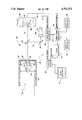
- FIGUREis a diagrammatic view of composite multispectral visible/thermal-infrared imaging apparatus in accordance with the invention.
- the inventionis particularly well adapted to providing a display of a composite visible/infrared image of an object or scene comprising a black and white visible image which is highlighted in color with infrared information, and will be described in that context.
- thisis illustrative of only one utility of the invention.
- composite visible/thermal-infrared imaging apparatusin accordance with the invention may generally comprise an optical system 10 for receiving visible and infrared radiation from an object or a scene and for providing a focused beam of radiation which is split into a first beam of visible radiation and a second beam of infrared radiation.
- the visible radiationis supplied to a first detector 12 which outputs a first signal corresponding to the visible radiation impinging upon the detector, and the infrared radiation is supplied to a second detector 14 which outputs a second signal corresponding to the infrared radiation impinging upon the second detector.
- the first and second signalsare supplied via respective channels 16 and 18 to a signal processing and display system 20 which processes the signals and produces a composite visible/thermal-infrared image of the scene within the field of view of the optical system.
- the composite imagemay be displayed on a conventional color monitor 22, for example, and preferably comprises a black and white (B/W) visible image of the scene with portions of the visible image highlighted in color in accordance with the infrared radiation received from corresponding portions of the scene.
- B/Wblack and white
- the output signals from detector 12, which correspond to the visible radiation impinging upon the detectormay be supplied via channel 16 to a first video frame generator 30 which formats the raw signals from the detector into gray scale black and white (B/W) image frames and outputs a corresponding B/W video signal.
- the video output signal from video frame generator 30may be supplied to a conventional video mixer 32, the output of which is supplied to the color monitor 22.
- the video signal from video frame generator 30is displayed on the color monitor as a B/W visible image of the scene within the field of view of the optical system.
- the signals from detector 14, which correspond to the infrared radiation impinging upon the detectormay be supplied via channel 18 to a second video frame generator 34 which converts the signals into frames of gray scale black and white video signals which are synchronized with the video signals from video frame generator 30.
- video frame generators 30 and 34may be driven by a common clock (CLK).
- Video frame generator 34preferably includes an adjustable lower threshold control 36 which enables adjustment of the lower sensitivity threshold of the infrared channel to a preselected value.
- This controlaffords an adjustable background threshold and advantageously allows low ambient temperature objects to be eliminated from the infrared display. Thus, only objects or portions of a scene having temperatures greater than a preselected value, i.e., producing infrared radiation greater than a preselected radiance value, are displayed. This is convenient for avoiding cluttering of the resulting composite display with low level background information.
- Video frame generator 34may also include a second upper threshold control 38 for setting an upper cut-off level so that objects or portions of the scene having temperatures greater than other preselected value may be eliminated from the display.
- the two controls 36 and 38thus afford an adjustable window which may be set so that only infrared signals within the preselected range between the upper and lower threshold limits are displayed. This is convenient for enabling objects or portions of a scene having temperatures within a predetermined temperature range to be highlighted on the display and to be easily identified. If desired, multiple threshold controls may be included to enable multiple adjustable infrared windows to be established.
- the video output signal from video frame generator 34may be supplied to a conventional color synthesizer or color slicer 40 which converts different discrete ranges of the video signal into different colors to produce a steptone false color (or saturated white) video signal corresponding to a color image of all objects within the field of view of the optical system having infrared intensities within the preselected range set by the adjustable threshold controls 36 and 38.
- the color video signal from the color synthesizermay be supplied to video mixer 32, where it is combined with the B/W video signal from video frame generator 30 to produce a composite image on color monitor 22.
- the composite imagecomprises a black and white visible image which is overlaid by a step-tone false color (or saturated white) thermal-infrared image.
- the black and white visible image and the step-tone false color infrared imageare in exact spatial registration.
- the composite imagethus comprises a visible image of the scene or object which is highlighted by infrared features with radiances between the preselected upper and lower threshold limits.
- either imagemay be separately displayed, and the video signals may be supplied to the other devices as desired.
- the signal processing and display system 20comprising the video frame generators, the color synthesizer, the video mixer, and the color monitor may be implemented with standard commercially available devices.
- Both video frame generatorsmay be substantially similar and may comprise any commercially available device capable of producing standard U.S. NTSC or European Pal TV video frame signals.
- the threshold controls 36 and 38 of video frame generator 34may simply comprise voltage threshold controls arranged such that only signals within the preselected threshold range are converted to a video output.
- color synthesizer 40may be a commerically available device for converting a gray scale black and white video signal into a color video signal.
- Optical system 10which receives the visible and infrared radiation and provides a focused beam of radiation, comprises a wavelength-independent, non-catadioptric, non-refractive reflective optical system.
- the optical systempreferably includes a reflective Cassegrain telescope, which is advantageous for affording compactness, comprising a cylindrical housing 50 having one end 52 which is open to provide an entrance for the radiation and an opposite end 54 which is closed except for a small diameter centrally located exit aperture 56.
- a cylindrical tubular member 58may extend inwardly a short distance into the housing from exit aperture 56, as shown.
- An annular concave primary mirror 60may be disposed within cylindrical housing 50 adjacent to closed end 54 with the tubular member 58 extending through an opening 62 in the mirror.
- a convex secondary mirror 64may be supported at an intermediate location along the axis of the housing by a support structure 66.
- Visible and infrared radiationentering opening 52 is reflected by the concave primary mirror 60 onto the secondary mirror 64, which in turn reflects the radiation so that it exits the housing through tubular member 58 and aperture 56 as a composite beam of visible and infrared radiation which is focused at a predetermined distance from the secondary mirror.
- the telescopemay be focused by a mechanical focusing system (not illustrated) which moves both the primary and secondary mirrors.
- the primary and secondary mirrorsare preferably coated with aluminum, silver, gold or other suitable material which has optimum reflection characteristics at both visible and infrared wavelengths, preferably throughout the 0.4-14 micrometer wavelength range.
- the focused beam of radiation from the telescopemay be split into a first beam 70 of visible radiation and a second beam 72 of infrared radiation by a silicon beam splitter 74 comprising a thin dichroic semiconductor, such as silicon, mirror.
- the silicon mirroris transparent at infrared wavelengths longer than approximately 2 micrometers and is reflecting at visible wavelengths.
- the beam splitter, 74may also be fabricated out of semiconducting materials other than silicon to change the wavelength limits of either the infrared or visible channel.
- a gallium arsenide beam-splitterbecomes transparent at approximately 0.9 microns wavelength. Accordingly, the infrared radiation passes through the mirror and is focused at a focal plane 76 at which the infrared detector 14 is located.
- the visible radiationis reflected by mirror 74 to a fully reflecting imaging erecting mirror 78 which reflects the focused visible radiation to a focal plane 80 at which the visible radiation detector 12 is located.
- Focal planes 76 and 80are located the same distance from the secondary mirror 64 of the telescope, and this distance corresponds to the focal point of the telescope.
- the image erecting mirror 78 for the visible radiationcancels the mirror image reversal caused by the beam splitter 74 so that the image size and orientation is identical at both the infrared and visible focal planes 76 and 80, thus insuring exact image registration in both wavelength channels.
- the optical systemSince the optical system is non-refractive, its focus is wavelength independent. Because of the widely separated visible and infrared wavelength bands and the necessity of providing a common focal plane distance for both the visible and infrared radiation, catadioptric (lens/mirror) and refractive optical systems are not suitable for the composite imaging system since the visible and infrared radiation would not be focused precisely at the same focal plane distance, which would cause problems in producing high resolution images that are in spatial registration.
- Visible radiation detector 12may comprise any conventional imaging detector of visible light, such as a solid state CCD or CID detector array, or a vidicon tube. Visible radiation detector 12 may also comprise any conventional imaging detector of visible light whose low light level response characteristics have been augmented by the addition of an eletro-optic image intensifier device. Also, visible radiation detector 12 and video frame generator 30 may comprise a television camera without the normal imaging lens. Infrared detector 14 may be a conventional focal plane infrared detector array, and may comprise, for example, a mechanically scanned infrared imaging radiometer without the normal imaging lens. For optimum infrared sensitivity, detector 14 is preferably operated at cryogenic temperatures, preferably at the order of 77° K. Accordingly, the detector may be disposed within a liquid nitrogen dewar 90 having infrared transparent windows 92 for admitting radiation. Alternatively, other cooling schemes, such as thermoelectric or Joule-Thompson refrigerators, may be employed for cooling the detector.
- other cooling schemessuch as thermoelectric or
Landscapes
- Engineering & Computer Science (AREA)
- Multimedia (AREA)
- Signal Processing (AREA)
- Physics & Mathematics (AREA)
- General Physics & Mathematics (AREA)
- Spectroscopy & Molecular Physics (AREA)
- Health & Medical Sciences (AREA)
- Toxicology (AREA)
- Radiation Pyrometers (AREA)
- Closed-Circuit Television Systems (AREA)
Abstract
Description
Claims (17)
Priority Applications (1)
| Application Number | Priority Date | Filing Date | Title |
|---|---|---|---|
| US07/079,209US4751571A (en) | 1987-07-29 | 1987-07-29 | Composite visible/thermal-infrared imaging apparatus |
Applications Claiming Priority (1)
| Application Number | Priority Date | Filing Date | Title |
|---|---|---|---|
| US07/079,209US4751571A (en) | 1987-07-29 | 1987-07-29 | Composite visible/thermal-infrared imaging apparatus |
Publications (1)
| Publication Number | Publication Date |
|---|---|
| US4751571Atrue US4751571A (en) | 1988-06-14 |
Family
ID=22149112
Family Applications (1)
| Application Number | Title | Priority Date | Filing Date |
|---|---|---|---|
| US07/079,209Expired - LifetimeUS4751571A (en) | 1987-07-29 | 1987-07-29 | Composite visible/thermal-infrared imaging apparatus |
Country Status (1)
| Country | Link |
|---|---|
| US (1) | US4751571A (en) |
Cited By (124)
| Publication number | Priority date | Publication date | Assignee | Title |
|---|---|---|---|---|
| US4881796A (en)* | 1988-08-08 | 1989-11-21 | Ford Aerospace Corporation | Single-aperture multi-spectral reticle projector |
| WO1989012941A1 (en)* | 1988-06-16 | 1989-12-28 | Valtion Teknillinen Tutkimuskeskus | Procedure and means for producing a false colour picture |
| FR2633475A1 (en)* | 1988-06-24 | 1989-12-29 | Labo Electronique Physique | LOW-LEVEL TV SYSTEM WITH COLOR IMAGES |
| US4939369A (en)* | 1988-10-04 | 1990-07-03 | Loral Fairchild Corporation | Imaging and tracking sensor designed with a sandwich structure |
| US4967276A (en)* | 1988-05-24 | 1990-10-30 | Fujitsu Limited | Video signal mixing device for infrared/visible integrated imaging |
| US4980554A (en)* | 1989-03-31 | 1990-12-25 | The United States Of America As Represented By The Secretary Of The Army | Laser line identifier |
| EP0392163A3 (en)* | 1989-04-14 | 1991-01-30 | Entech Engineering, Inc. | System for geological defect detection utilizing composite video-infrared thermography |
| US4991020A (en)* | 1989-02-17 | 1991-02-05 | Hughes Aircraft Company | Imaging system for providing separate simultaneous real time images from a singel image sensor |
| EP0384009A3 (en)* | 1989-02-23 | 1991-10-23 | Rheinmetall Industrie GmbH | Device for obtaining high-contrast images |
| US5107333A (en)* | 1989-08-08 | 1992-04-21 | Thomson-Csf | Bispectral pick-up and false color display system |
| US5181145A (en)* | 1990-03-14 | 1993-01-19 | State Of Israel - Ministry Of Defence Armament Development Authority | Optical imaging system made from a single piece of material |
| WO1993011630A1 (en)* | 1991-11-27 | 1993-06-10 | Valtion Teknillinen Tutkimuskeskus | Method and apparatus for producing a false colour image |
| US5292195A (en)* | 1992-09-09 | 1994-03-08 | Martin Marietta Corporation | Thermographic evaluation technique |
| US5311018A (en)* | 1993-02-11 | 1994-05-10 | The United States Of America As Represented By The Secretary Of The Air Force | Optical system for obtaining separate and simultaneous near-infrared and visible light images |
| US5414439A (en)* | 1994-06-09 | 1995-05-09 | Delco Electronics Corporation | Head up display with night vision enhancement |
| US5453618A (en)* | 1994-01-31 | 1995-09-26 | Litton Systems, Inc. | Miniature infrared line-scanning imager |
| US5481401A (en)* | 1991-05-16 | 1996-01-02 | Olympus Optical Co., Ltd. | Ultraviolet microscope |
| US5497266A (en)* | 1994-07-27 | 1996-03-05 | Litton Systems, Inc. | Telescopic day and night sight |
| US5555324A (en)* | 1994-11-01 | 1996-09-10 | Massachusetts Institute Of Technology | Method and apparatus for generating a synthetic image by the fusion of signals representative of different views of the same scene |
| US5574511A (en)* | 1995-10-18 | 1996-11-12 | Polaroid Corporation | Background replacement for an image |
| WO1996041481A1 (en)* | 1995-06-07 | 1996-12-19 | Stryker Corporation | Imaging system with independent processing of visible and infrared light energy |
| US5811815A (en)* | 1995-11-15 | 1998-09-22 | Lockheed-Martin Ir Imaging Systems, Inc. | Dual-band multi-level microbridge detector |
| US5831762A (en)* | 1996-06-21 | 1998-11-03 | Raytheon Company | Imaging sensor having multiple fields of view and utilizing all-reflective optics |
| US5900942A (en)* | 1997-09-26 | 1999-05-04 | The United States Of America As Represented By Administrator Of National Aeronautics And Space Administration | Multi spectral imaging system |
| US5910816A (en)* | 1995-06-07 | 1999-06-08 | Stryker Corporation | Imaging system with independent processing of visible an infrared light energy |
| US5946132A (en)* | 1991-01-18 | 1999-08-31 | Itt Corporation | Telescopic sight for day/night viewing |
| WO1999050701A1 (en)* | 1998-03-31 | 1999-10-07 | Raytheon Company | Compact electro-optical sensor assembly having single aperture for multiple detectors |
| US6009340A (en)* | 1998-03-16 | 1999-12-28 | Northrop Grumman Corporation | Multimode, multispectral imaging system |
| US6076734A (en)* | 1997-10-07 | 2000-06-20 | Interval Research Corporation | Methods and systems for providing human/computer interfaces |
| US6150930A (en)* | 1992-08-14 | 2000-11-21 | Texas Instruments Incorporated | Video equipment and method to assist motor vehicle operators |
| US6164541A (en)* | 1997-10-10 | 2000-12-26 | Interval Research Group | Methods and systems for providing human/computer interfaces |
| US6198503B1 (en)* | 1993-08-20 | 2001-03-06 | Steve Weinreich | Infra-red video key |
| US6256638B1 (en) | 1998-04-14 | 2001-07-03 | Interval Research Corporation | Printable interfaces and digital linkmarks |
| KR20010072091A (en)* | 1998-03-13 | 2001-07-31 | 피터 엔. 데트킨 | Color imaging system with infrared correction |
| US6292212B1 (en)* | 1994-12-23 | 2001-09-18 | Eastman Kodak Company | Electronic color infrared camera |
| WO2001072033A1 (en)* | 2000-03-20 | 2001-09-27 | Litton Systems, Inc. | Method and system for combining multi-spectral images |
| US20010037313A1 (en)* | 2000-05-01 | 2001-11-01 | Neil Lofgren | Digital watermarking systems |
| US6408331B1 (en) | 1995-07-27 | 2002-06-18 | Digimarc Corporation | Computer linking methods using encoded graphics |
| US6411725B1 (en) | 1995-07-27 | 2002-06-25 | Digimarc Corporation | Watermark enabled video objects |
| US20020135571A1 (en)* | 2000-12-21 | 2002-09-26 | Paul Klocek | Method and apparatus for generating a visible image with an infrared transmissive window |
| GB2373943A (en)* | 2001-03-28 | 2002-10-02 | Hewlett Packard Co | Visible and infrared imaging camera |
| US20020173723A1 (en)* | 1999-07-02 | 2002-11-21 | Lewis Edgar N. | Dual imaging apparatus |
| US6516216B1 (en) | 1996-02-23 | 2003-02-04 | Stryker Corporation | Circumferential transillumination of anatomic junctions using light energy |
| US20030025799A1 (en)* | 2001-08-04 | 2003-02-06 | Michael Holz | Process for improving the view in vehicles |
| US6647130B2 (en) | 1993-11-18 | 2003-11-11 | Digimarc Corporation | Printable interfaces and digital linking with embedded codes |
| US6650357B1 (en)* | 1997-04-09 | 2003-11-18 | Richardson Technologies, Inc. | Color translating UV microscope |
| US20030231804A1 (en)* | 2002-06-12 | 2003-12-18 | Litton Systems, Inc. | System for multi-sensor image fusion |
| WO2003104877A1 (en) | 2002-06-05 | 2003-12-18 | Litton Systems, Inc. | Enhanced night vision goggle assembly |
| US20030230707A1 (en)* | 2002-06-12 | 2003-12-18 | Litton Systems, Inc. | Image intensification camera |
| US20030231245A1 (en)* | 2002-06-12 | 2003-12-18 | Litton Systems, Inc. | Ingaas image intensifier camera |
| US20030231410A1 (en)* | 2002-06-12 | 2003-12-18 | Litton Systems, Inc. | Method and system for mounting a detector |
| US20030234870A1 (en)* | 2002-06-12 | 2003-12-25 | Litton Systems, Inc. | Event synchronization for detector systems |
| WO2003107067A3 (en)* | 2002-06-18 | 2004-04-08 | Bayerische Motoren Werke Ag | METHOD AND DEVICE FOR VISUALIZING THE SURROUNDINGS OF A VEHICLE WITH A DISTANCE-DEPENDENT FUSION OF AN INFRARED AND A VISUAL IMAGE |
| DE4136250B4 (en)* | 1990-04-07 | 2004-09-09 | Bae Systems Electronics Ltd., Farnborough | Thermal imaging system |
| US20040196566A1 (en)* | 2002-06-06 | 2004-10-07 | Litton Systems, Inc. | Integrated display image intensifier assembly |
| US20040208223A1 (en)* | 2003-04-18 | 2004-10-21 | Shimadzu Corporation | Two-color radiation thermometer |
| US20040236229A1 (en)* | 1999-07-02 | 2004-11-25 | Freeman Jenny E. | Integrated imaging apparatus |
| US20050008190A1 (en)* | 1995-07-27 | 2005-01-13 | Levy Kenneth L. | Digital watermarking systems and methods |
| US20050013482A1 (en)* | 2000-11-07 | 2005-01-20 | Niesen Joseph W. | True color infrared photography and video |
| US6906725B2 (en) | 2002-02-22 | 2005-06-14 | L-3 Communications Corporation | Apparatus and method for simulating sensor imagery |
| US20060033998A1 (en)* | 2004-08-12 | 2006-02-16 | E.D. Bullard Company | Method and system for thermal imaging having a selective temperature imaging mode |
| WO2006084534A1 (en)* | 2005-02-11 | 2006-08-17 | Bayerische Motoren Werke Aktiengesellschaft | Method and device for visualising the surroundings of a vehicle by merging an infrared image and a visual image |
| US20060249679A1 (en)* | 2004-12-03 | 2006-11-09 | Johnson Kirk R | Visible light and ir combined image camera |
| EP1064789A4 (en)* | 1998-02-25 | 2007-05-23 | Thermal Wave Imaging Inc | Data integration and registration method and apparatus for non-destructive evaluation of materials |
| EP1410419A4 (en)* | 2001-06-22 | 2007-08-22 | Litton Systems Inc | Collecting image data with multiple sensors |
| US20070222854A1 (en)* | 2006-03-24 | 2007-09-27 | Omnitech Partners | Image combining viewer |
| US20070235634A1 (en)* | 2004-07-02 | 2007-10-11 | Ottney Joseph C | Fusion night vision system |
| WO2007135613A1 (en)* | 2006-05-24 | 2007-11-29 | Koninklijke Philips Electronics N.V. | An imaging apparatus for combined temperature and luminescence spatial imaging of an object |
| US20080025640A1 (en)* | 2006-07-25 | 2008-01-31 | Itt Manufacturing Enterprises, Inc. | Motion compensated image registration for overlaid/fused video |
| US20080099678A1 (en)* | 2004-12-03 | 2008-05-01 | Johnson Kirk R | Camera with visible light and infrared image blending |
| US20080245966A1 (en)* | 2005-05-18 | 2008-10-09 | Lockheed Martin Corporation | Long-wavelength infra-red night vision goggles |
| US20080290278A1 (en)* | 2002-02-26 | 2008-11-27 | Uni-Pixel Displays, Inc. | Visible plus non-visible field sequential color |
| US20090018721A1 (en)* | 2006-10-27 | 2009-01-15 | Mian Zahid F | Vehicle evaluation using infrared data |
| US20090050806A1 (en)* | 2004-12-03 | 2009-02-26 | Fluke Corporation | Visible light and ir combined image camera with a laser pointer |
| US20090285476A1 (en)* | 2008-05-19 | 2009-11-19 | Won-Hee Choe | Apparatus and method for combining images |
| DE102008046965A1 (en)* | 2008-09-12 | 2010-03-25 | Siemens Aktiengesellschaft | Image recording unit for fusion of images producing different wavelength sensitivity with sensors, has switching unit provided for switching radiation coming on optical unit from image with wavelength |
| US20100100275A1 (en)* | 2008-10-22 | 2010-04-22 | Mian Zahid F | Thermal imaging-based vehicle analysis |
| US20100102228A1 (en)* | 2008-10-29 | 2010-04-29 | Asia Optical Co., Inc. | Image Recording Apparatus And Control Method Thereof |
| US20100108885A1 (en)* | 2007-03-27 | 2010-05-06 | Dsam London Llp | Imaging system with an optical mirror arrangement and self righting housing |
| US7834905B2 (en) | 2002-06-18 | 2010-11-16 | Bayerische Motoren Werke Aktiengesellschaft | Method and system for visualizing the environment of a vehicle with a distance-dependent merging of an infrared and a visual image |
| US20100310113A1 (en)* | 2009-06-05 | 2010-12-09 | Air Products And Chemicals, Inc. | System And Method For Temperature Data Acquisition |
| DE102009035121A1 (en)* | 2009-07-29 | 2011-02-03 | Tekfor Cologne Gmbh | Process for processing workpieces |
| US20110113993A1 (en)* | 2009-11-19 | 2011-05-19 | Air Products And Chemicals, Inc. | Method of Operating a Furnace |
| US20110199605A1 (en)* | 2010-02-18 | 2011-08-18 | Rafael Advanced Defense Systems Ltd. | System and method for changing spectral range of a cryogenically cooled detector |
| DE102010010370A1 (en)* | 2010-03-05 | 2011-11-17 | Siemens Aktiengesellschaft | Hybrid infrared camera |
| WO2011124368A3 (en)* | 2010-04-07 | 2011-12-08 | Projectiondesign As | Interweaving of ir and visible images |
| US20140022373A1 (en)* | 2012-07-20 | 2014-01-23 | University Of Utah Research Foundation | Correlative drift correction |
| US20140053568A1 (en)* | 2012-08-23 | 2014-02-27 | Clifford Hatcher, JR. | System and method for on line monitoring within a gas turbine combustor section |
| CN104048765A (en)* | 2014-06-11 | 2014-09-17 | 中国科学院高能物理研究所 | Infrared imaging device based on coding bore diameters |
| US20140332665A1 (en)* | 2010-04-21 | 2014-11-13 | Sionyx, Inc. | Photosensitive imaging devices and associated methods |
| US8913131B2 (en) | 2002-06-04 | 2014-12-16 | General Electric Company | Locomotive wireless video recorder and recording system |
| US20160112657A1 (en)* | 2004-08-25 | 2016-04-21 | Callahan Cellular L.L.C. | Large dynamic range cameras |
| US9481385B2 (en) | 2014-01-09 | 2016-11-01 | General Electric Company | Systems and methods for predictive maintenance of crossings |
| US9496308B2 (en) | 2011-06-09 | 2016-11-15 | Sionyx, Llc | Process module for increasing the response of backside illuminated photosensitive imagers and associated methods |
| US9673243B2 (en) | 2009-09-17 | 2017-06-06 | Sionyx, Llc | Photosensitive imaging devices and associated methods |
| US9673250B2 (en) | 2013-06-29 | 2017-06-06 | Sionyx, Llc | Shallow trench textured regions and associated methods |
| US9762830B2 (en) | 2013-02-15 | 2017-09-12 | Sionyx, Llc | High dynamic range CMOS image sensor having anti-blooming properties and associated methods |
| US9761739B2 (en) | 2010-06-18 | 2017-09-12 | Sionyx, Llc | High speed photosensitive devices and associated methods |
| DE102016110743A1 (en)* | 2016-06-10 | 2017-12-14 | Airbus Ds Optronics Gmbh | Optronic sensor device |
| US9875414B2 (en) | 2014-04-15 | 2018-01-23 | General Electric Company | Route damage prediction system and method |
| US9873442B2 (en) | 2002-06-04 | 2018-01-23 | General Electric Company | Aerial camera system and method for identifying route-related hazards |
| US9905599B2 (en) | 2012-03-22 | 2018-02-27 | Sionyx, Llc | Pixel isolation elements, devices and associated methods |
| US9911781B2 (en) | 2009-09-17 | 2018-03-06 | Sionyx, Llc | Photosensitive imaging devices and associated methods |
| US9939251B2 (en) | 2013-03-15 | 2018-04-10 | Sionyx, Llc | Three dimensional imaging utilizing stacked imager devices and associated methods |
| US10006877B2 (en) | 2014-08-20 | 2018-06-26 | General Electric Company | Route examining system and method |
| CN108344738A (en)* | 2018-01-22 | 2018-07-31 | 翰飞骏德(北京)医疗科技有限公司 | Imaging method and its device for hydroxyapatite |
| US10049298B2 (en) | 2014-02-17 | 2018-08-14 | General Electric Company | Vehicle image data management system and method |
| US10057509B2 (en) | 2014-05-30 | 2018-08-21 | Flir Systems, Inc. | Multiple-sensor imaging system |
| US10142548B2 (en) | 2004-08-25 | 2018-11-27 | Callahan Cellular L.L.C. | Digital camera with multiple pipeline signal processors |
| US10148927B2 (en) | 2005-08-25 | 2018-12-04 | Callahan Cellular L.L.C. | Digital cameras with direct luminance and chrominance detection |
| US10244188B2 (en) | 2011-07-13 | 2019-03-26 | Sionyx, Llc | Biometric imaging devices and associated methods |
| US20190197749A1 (en)* | 2017-12-27 | 2019-06-27 | Po-Wen Wang | Method of Displaying Object Temperature |
| US10361083B2 (en) | 2004-09-24 | 2019-07-23 | President And Fellows Of Harvard College | Femtosecond laser-induced formation of submicrometer spikes on a semiconductor substrate |
| US10359618B2 (en) | 2016-01-11 | 2019-07-23 | Nikon Corporation | Multispectral stereoscopic endoscope system and use of same |
| US10374109B2 (en) | 2001-05-25 | 2019-08-06 | President And Fellows Of Harvard College | Silicon-based visible and near-infrared optoelectric devices |
| RU2711628C1 (en)* | 2019-04-02 | 2020-01-17 | Публичное Акционерное общество "Ростовский оптико-механический завод" (ПАО РОМЗ) | Night vision goggles |
| US10594956B2 (en) | 2016-09-27 | 2020-03-17 | Rxsafe Llc | Verification system for a pharmacy packaging system |
| US10701244B2 (en)* | 2016-09-30 | 2020-06-30 | Microsoft Technology Licensing, Llc | Recolorization of infrared image streams |
| US10746470B2 (en) | 2017-06-29 | 2020-08-18 | Air Products & Chemicals, Inc. | Method of operating a furnace |
| US11124207B2 (en) | 2014-03-18 | 2021-09-21 | Transportation Ip Holdings, Llc | Optical route examination system and method |
| WO2021253187A1 (en)* | 2020-06-15 | 2021-12-23 | 深圳市大疆创新科技有限公司 | Infrared image processing method, image acquisition device, image processing device, and computer readable storage medium |
| US11348335B2 (en)* | 2018-04-05 | 2022-05-31 | Efficiency Matrix Pty Ltd | Computer implemented structural thermal audit systems and methods |
| US11595595B2 (en) | 2016-09-27 | 2023-02-28 | Rxsafe Llc | Verification system for a pharmacy packaging system |
| US12134494B2 (en) | 2022-01-03 | 2024-11-05 | Rxsafe, Llc | Verification system for a pharmacy packaging system |
Citations (16)
| Publication number | Priority date | Publication date | Assignee | Title |
|---|---|---|---|---|
| US3588347A (en)* | 1969-03-13 | 1971-06-28 | Western Electric Co | Method and apparatus for aligning a mask and a substrate using infrared radiation |
| US3742124A (en)* | 1971-08-16 | 1973-06-26 | Texas Instruments Inc | Color infrared detecting set |
| US3748471A (en)* | 1971-09-24 | 1973-07-24 | Int Imaging Syst | False color radiant energy detection method and apparatus |
| US3763357A (en)* | 1971-12-22 | 1973-10-02 | Bausch & Lomb | Threshold circuit for converting a video signal to a binary video signal |
| US3806633A (en)* | 1972-01-18 | 1974-04-23 | Westinghouse Electric Corp | Multispectral data sensor and display system |
| US4086616A (en)* | 1976-12-23 | 1978-04-25 | The United States Of America As Represented By The Secretary Of The Navy | All-weather multi-spectral imaging system |
| US4118733A (en)* | 1976-03-30 | 1978-10-03 | Elliott Brothers (London) Limited | Surveillance arrangement including a television system and infrared detector means |
| JPS53116729A (en)* | 1977-03-23 | 1978-10-12 | Mitsubishi Electric Corp | Video unit |
| US4162052A (en)* | 1975-12-22 | 1979-07-24 | Societe Anonyme De Telecommunications | Night guidance of self-propelled missiles |
| US4170987A (en)* | 1977-11-28 | 1979-10-16 | California Institute Of Technology | Medical diagnosis system and method with multispectral imaging |
| US4220972A (en)* | 1979-05-22 | 1980-09-02 | Honeywell Inc. | Low contrast object extraction device |
| US4431917A (en)* | 1981-11-27 | 1984-02-14 | Texas Instruments Incorporated | Compact, high cold shield efficiency optical system |
| US4608599A (en)* | 1983-07-28 | 1986-08-26 | Matsushita Electric Industrial Co., Ltd. | Infrared image pickup image |
| US4608597A (en)* | 1982-11-02 | 1986-08-26 | Gx-Holding Ag | Method for the surveyance of an object space |
| US4646140A (en)* | 1984-09-25 | 1987-02-24 | English Electric Valve Company Limited | Television cameras |
| US4679068A (en)* | 1985-07-25 | 1987-07-07 | General Electric Company | Composite visible/thermal-infrared imaging system |
- 1987
- 1987-07-29USUS07/079,209patent/US4751571A/ennot_activeExpired - Lifetime
Patent Citations (16)
| Publication number | Priority date | Publication date | Assignee | Title |
|---|---|---|---|---|
| US3588347A (en)* | 1969-03-13 | 1971-06-28 | Western Electric Co | Method and apparatus for aligning a mask and a substrate using infrared radiation |
| US3742124A (en)* | 1971-08-16 | 1973-06-26 | Texas Instruments Inc | Color infrared detecting set |
| US3748471A (en)* | 1971-09-24 | 1973-07-24 | Int Imaging Syst | False color radiant energy detection method and apparatus |
| US3763357A (en)* | 1971-12-22 | 1973-10-02 | Bausch & Lomb | Threshold circuit for converting a video signal to a binary video signal |
| US3806633A (en)* | 1972-01-18 | 1974-04-23 | Westinghouse Electric Corp | Multispectral data sensor and display system |
| US4162052A (en)* | 1975-12-22 | 1979-07-24 | Societe Anonyme De Telecommunications | Night guidance of self-propelled missiles |
| US4118733A (en)* | 1976-03-30 | 1978-10-03 | Elliott Brothers (London) Limited | Surveillance arrangement including a television system and infrared detector means |
| US4086616A (en)* | 1976-12-23 | 1978-04-25 | The United States Of America As Represented By The Secretary Of The Navy | All-weather multi-spectral imaging system |
| JPS53116729A (en)* | 1977-03-23 | 1978-10-12 | Mitsubishi Electric Corp | Video unit |
| US4170987A (en)* | 1977-11-28 | 1979-10-16 | California Institute Of Technology | Medical diagnosis system and method with multispectral imaging |
| US4220972A (en)* | 1979-05-22 | 1980-09-02 | Honeywell Inc. | Low contrast object extraction device |
| US4431917A (en)* | 1981-11-27 | 1984-02-14 | Texas Instruments Incorporated | Compact, high cold shield efficiency optical system |
| US4608597A (en)* | 1982-11-02 | 1986-08-26 | Gx-Holding Ag | Method for the surveyance of an object space |
| US4608599A (en)* | 1983-07-28 | 1986-08-26 | Matsushita Electric Industrial Co., Ltd. | Infrared image pickup image |
| US4646140A (en)* | 1984-09-25 | 1987-02-24 | English Electric Valve Company Limited | Television cameras |
| US4679068A (en)* | 1985-07-25 | 1987-07-07 | General Electric Company | Composite visible/thermal-infrared imaging system |
Non-Patent Citations (2)
| Title |
|---|
| Martin, T. Z.; "Camera for Monitoring Vegetation", NASA Tech Brief; vol. 9, No. 3; JPL; Sep. 1985. |
| Martin, T. Z.; Camera for Monitoring Vegetation , NASA Tech Brief; vol. 9, No. 3; JPL; Sep. 1985.* |
Cited By (224)
| Publication number | Priority date | Publication date | Assignee | Title |
|---|---|---|---|---|
| US4967276A (en)* | 1988-05-24 | 1990-10-30 | Fujitsu Limited | Video signal mixing device for infrared/visible integrated imaging |
| WO1989012941A1 (en)* | 1988-06-16 | 1989-12-28 | Valtion Teknillinen Tutkimuskeskus | Procedure and means for producing a false colour picture |
| US5051821A (en)* | 1988-06-24 | 1991-09-24 | U.S. Philips Corp. | Low light level color image television system including electronic contrast enhancement system |
| FR2633475A1 (en)* | 1988-06-24 | 1989-12-29 | Labo Electronique Physique | LOW-LEVEL TV SYSTEM WITH COLOR IMAGES |
| EP0352831A1 (en)* | 1988-06-24 | 1990-01-31 | Laboratoires D'electronique Philips | Television system for producing colour pictures at a low light intensity level |
| US4881796A (en)* | 1988-08-08 | 1989-11-21 | Ford Aerospace Corporation | Single-aperture multi-spectral reticle projector |
| US4939369A (en)* | 1988-10-04 | 1990-07-03 | Loral Fairchild Corporation | Imaging and tracking sensor designed with a sandwich structure |
| US4991020A (en)* | 1989-02-17 | 1991-02-05 | Hughes Aircraft Company | Imaging system for providing separate simultaneous real time images from a singel image sensor |
| EP0384009A3 (en)* | 1989-02-23 | 1991-10-23 | Rheinmetall Industrie GmbH | Device for obtaining high-contrast images |
| US4980554A (en)* | 1989-03-31 | 1990-12-25 | The United States Of America As Represented By The Secretary Of The Army | Laser line identifier |
| EP0392163A3 (en)* | 1989-04-14 | 1991-01-30 | Entech Engineering, Inc. | System for geological defect detection utilizing composite video-infrared thermography |
| US5107333A (en)* | 1989-08-08 | 1992-04-21 | Thomson-Csf | Bispectral pick-up and false color display system |
| US5181145A (en)* | 1990-03-14 | 1993-01-19 | State Of Israel - Ministry Of Defence Armament Development Authority | Optical imaging system made from a single piece of material |
| DE4136250B4 (en)* | 1990-04-07 | 2004-09-09 | Bae Systems Electronics Ltd., Farnborough | Thermal imaging system |
| US5946132A (en)* | 1991-01-18 | 1999-08-31 | Itt Corporation | Telescopic sight for day/night viewing |
| US5481401A (en)* | 1991-05-16 | 1996-01-02 | Olympus Optical Co., Ltd. | Ultraviolet microscope |
| WO1993011630A1 (en)* | 1991-11-27 | 1993-06-10 | Valtion Teknillinen Tutkimuskeskus | Method and apparatus for producing a false colour image |
| US5557326A (en)* | 1991-11-27 | 1996-09-17 | Valtion Teknillinen Tutkimuskeskus | Method and apparatus for producing a false color image |
| US6150930A (en)* | 1992-08-14 | 2000-11-21 | Texas Instruments Incorporated | Video equipment and method to assist motor vehicle operators |
| US5292195A (en)* | 1992-09-09 | 1994-03-08 | Martin Marietta Corporation | Thermographic evaluation technique |
| US5311018A (en)* | 1993-02-11 | 1994-05-10 | The United States Of America As Represented By The Secretary Of The Air Force | Optical system for obtaining separate and simultaneous near-infrared and visible light images |
| US6198503B1 (en)* | 1993-08-20 | 2001-03-06 | Steve Weinreich | Infra-red video key |
| US6647130B2 (en) | 1993-11-18 | 2003-11-11 | Digimarc Corporation | Printable interfaces and digital linking with embedded codes |
| US5453618A (en)* | 1994-01-31 | 1995-09-26 | Litton Systems, Inc. | Miniature infrared line-scanning imager |
| EP0686865A1 (en)* | 1994-06-09 | 1995-12-13 | Delco Electronics Corporation | Night vision system for motor vehicles |
| US5414439A (en)* | 1994-06-09 | 1995-05-09 | Delco Electronics Corporation | Head up display with night vision enhancement |
| US5497266A (en)* | 1994-07-27 | 1996-03-05 | Litton Systems, Inc. | Telescopic day and night sight |
| US5555324A (en)* | 1994-11-01 | 1996-09-10 | Massachusetts Institute Of Technology | Method and apparatus for generating a synthetic image by the fusion of signals representative of different views of the same scene |
| US6292212B1 (en)* | 1994-12-23 | 2001-09-18 | Eastman Kodak Company | Electronic color infrared camera |
| WO1996041481A1 (en)* | 1995-06-07 | 1996-12-19 | Stryker Corporation | Imaging system with independent processing of visible and infrared light energy |
| US5910816A (en)* | 1995-06-07 | 1999-06-08 | Stryker Corporation | Imaging system with independent processing of visible an infrared light energy |
| US7050603B2 (en) | 1995-07-27 | 2006-05-23 | Digimarc Corporation | Watermark encoded video, and related methods |
| US7436976B2 (en) | 1995-07-27 | 2008-10-14 | Digimarc Corporation | Digital watermarking systems and methods |
| US6411725B1 (en) | 1995-07-27 | 2002-06-25 | Digimarc Corporation | Watermark enabled video objects |
| US6408331B1 (en) | 1995-07-27 | 2002-06-18 | Digimarc Corporation | Computer linking methods using encoded graphics |
| US20050008190A1 (en)* | 1995-07-27 | 2005-01-13 | Levy Kenneth L. | Digital watermarking systems and methods |
| US5923380A (en)* | 1995-10-18 | 1999-07-13 | Polaroid Corporation | Method for replacing the background of an image |
| US5574511A (en)* | 1995-10-18 | 1996-11-12 | Polaroid Corporation | Background replacement for an image |
| US6157404A (en)* | 1995-11-15 | 2000-12-05 | Lockheed-Martin Ir Imaging Systems, Inc. | Imaging system including an array of dual-band microbridge detectors |
| US5811815A (en)* | 1995-11-15 | 1998-09-22 | Lockheed-Martin Ir Imaging Systems, Inc. | Dual-band multi-level microbridge detector |
| US6516216B1 (en) | 1996-02-23 | 2003-02-04 | Stryker Corporation | Circumferential transillumination of anatomic junctions using light energy |
| US5831762A (en)* | 1996-06-21 | 1998-11-03 | Raytheon Company | Imaging sensor having multiple fields of view and utilizing all-reflective optics |
| US6961080B2 (en)* | 1997-04-09 | 2005-11-01 | Richardson Technologies Inc. | Color translating UV microscope |
| US20040114219A1 (en)* | 1997-04-09 | 2004-06-17 | Tim Richardson | Color translating UV microscope |
| US6650357B1 (en)* | 1997-04-09 | 2003-11-18 | Richardson Technologies, Inc. | Color translating UV microscope |
| US5900942A (en)* | 1997-09-26 | 1999-05-04 | The United States Of America As Represented By Administrator Of National Aeronautics And Space Administration | Multi spectral imaging system |
| US6540141B1 (en) | 1997-10-07 | 2003-04-01 | Interval Research Corporation | Methods and systems for providing human/computer interfaces |
| US6439459B1 (en) | 1997-10-07 | 2002-08-27 | Interval Research Corporation | Methods and systems for providing human/computer interfaces |
| US6076734A (en)* | 1997-10-07 | 2000-06-20 | Interval Research Corporation | Methods and systems for providing human/computer interfaces |
| US6989816B1 (en) | 1997-10-07 | 2006-01-24 | Vulcan Patents Llc | Methods and systems for providing human/computer interfaces |
| US6587859B2 (en) | 1997-10-07 | 2003-07-01 | Interval Research Corporation | Printable interfaces and digital linkmarks |
| US6518950B1 (en) | 1997-10-07 | 2003-02-11 | Interval Research Corporation | Methods and systems for providing human/computer interfaces |
| US6164541A (en)* | 1997-10-10 | 2000-12-26 | Interval Research Group | Methods and systems for providing human/computer interfaces |
| EP1064789A4 (en)* | 1998-02-25 | 2007-05-23 | Thermal Wave Imaging Inc | Data integration and registration method and apparatus for non-destructive evaluation of materials |
| KR20010072091A (en)* | 1998-03-13 | 2001-07-31 | 피터 엔. 데트킨 | Color imaging system with infrared correction |
| US6009340A (en)* | 1998-03-16 | 1999-12-28 | Northrop Grumman Corporation | Multimode, multispectral imaging system |
| US6174061B1 (en) | 1998-03-31 | 2001-01-16 | Raytheon Company | Compact electro-optical sensor assembly having single aperture for multiple detectors |
| WO1999050701A1 (en)* | 1998-03-31 | 1999-10-07 | Raytheon Company | Compact electro-optical sensor assembly having single aperture for multiple detectors |
| US6256638B1 (en) | 1998-04-14 | 2001-07-03 | Interval Research Corporation | Printable interfaces and digital linkmarks |
| US20040236229A1 (en)* | 1999-07-02 | 2004-11-25 | Freeman Jenny E. | Integrated imaging apparatus |
| US20020173723A1 (en)* | 1999-07-02 | 2002-11-21 | Lewis Edgar N. | Dual imaging apparatus |
| US7053928B1 (en) | 2000-03-20 | 2006-05-30 | Litton Systems, Inc. | Method and system for combining multi-spectral images of a scene |
| WO2001072033A1 (en)* | 2000-03-20 | 2001-09-27 | Litton Systems, Inc. | Method and system for combining multi-spectral images |
| US7111168B2 (en) | 2000-05-01 | 2006-09-19 | Digimarc Corporation | Digital watermarking systems |
| US20010037313A1 (en)* | 2000-05-01 | 2001-11-01 | Neil Lofgren | Digital watermarking systems |
| US7079682B2 (en)* | 2000-11-07 | 2006-07-18 | Niesen Joseph W | True color infrared photography and video |
| US20050013482A1 (en)* | 2000-11-07 | 2005-01-20 | Niesen Joseph W. | True color infrared photography and video |
| US6833822B2 (en)* | 2000-12-21 | 2004-12-21 | Raytheon Company | Method and apparatus for generating a visible image with an infrared transmissive window |
| US20020135571A1 (en)* | 2000-12-21 | 2002-09-26 | Paul Klocek | Method and apparatus for generating a visible image with an infrared transmissive window |
| US7365771B2 (en) | 2001-03-28 | 2008-04-29 | Hewlett-Packard Development Company, L.P. | Camera with visible and infra-red imaging |
| GB2373943A (en)* | 2001-03-28 | 2002-10-02 | Hewlett Packard Co | Visible and infrared imaging camera |
| US20020140822A1 (en)* | 2001-03-28 | 2002-10-03 | Kahn Richard Oliver | Camera with visible and infra-red imaging |
| US10374109B2 (en) | 2001-05-25 | 2019-08-06 | President And Fellows Of Harvard College | Silicon-based visible and near-infrared optoelectric devices |
| EP1410419A4 (en)* | 2001-06-22 | 2007-08-22 | Litton Systems Inc | Collecting image data with multiple sensors |
| US20030025799A1 (en)* | 2001-08-04 | 2003-02-06 | Michael Holz | Process for improving the view in vehicles |
| US6906725B2 (en) | 2002-02-22 | 2005-06-14 | L-3 Communications Corporation | Apparatus and method for simulating sensor imagery |
| US20080290278A1 (en)* | 2002-02-26 | 2008-11-27 | Uni-Pixel Displays, Inc. | Visible plus non-visible field sequential color |
| US20090262129A1 (en)* | 2002-02-26 | 2009-10-22 | Uni-Pixel Displays, Inc. | Extending the gamut color generation in a display |
| US8014057B2 (en) | 2002-02-26 | 2011-09-06 | Rambus Inc. | Extending the gamut color generation in a display |
| US8077376B2 (en) | 2002-02-26 | 2011-12-13 | Rambus Inc. | Visible plus non-visible field sequential color |
| US9873442B2 (en) | 2002-06-04 | 2018-01-23 | General Electric Company | Aerial camera system and method for identifying route-related hazards |
| US8913131B2 (en) | 2002-06-04 | 2014-12-16 | General Electric Company | Locomotive wireless video recorder and recording system |
| US6762884B2 (en) | 2002-06-05 | 2004-07-13 | Litton Systems, Inc, | Enhanced night vision goggle assembly |
| WO2003104877A1 (en) | 2002-06-05 | 2003-12-18 | Litton Systems, Inc. | Enhanced night vision goggle assembly |
| EP1549993A4 (en)* | 2002-06-05 | 2007-05-30 | Litton Systems Inc | Enhanced night vision goggle assembly |
| US20040042086A1 (en)* | 2002-06-05 | 2004-03-04 | Litton Systems, Inc. | Enhanced night vision goggle assembly |
| US20040196566A1 (en)* | 2002-06-06 | 2004-10-07 | Litton Systems, Inc. | Integrated display image intensifier assembly |
| US20030231245A1 (en)* | 2002-06-12 | 2003-12-18 | Litton Systems, Inc. | Ingaas image intensifier camera |
| US20030234870A1 (en)* | 2002-06-12 | 2003-12-25 | Litton Systems, Inc. | Event synchronization for detector systems |
| US20030231410A1 (en)* | 2002-06-12 | 2003-12-18 | Litton Systems, Inc. | Method and system for mounting a detector |
| US20030231804A1 (en)* | 2002-06-12 | 2003-12-18 | Litton Systems, Inc. | System for multi-sensor image fusion |
| US7092013B2 (en) | 2002-06-12 | 2006-08-15 | Litton Systems, Inc. | InGaAs image intensifier camera |
| US6970190B2 (en) | 2002-06-12 | 2005-11-29 | Litton Systems, Inc. | Event synchronization for detector systems |
| US20030230707A1 (en)* | 2002-06-12 | 2003-12-18 | Litton Systems, Inc. | Image intensification camera |
| US7274830B2 (en) | 2002-06-12 | 2007-09-25 | Litton Systems, Inc. | System for multi-sensor image fusion |
| WO2003106951A3 (en)* | 2002-06-12 | 2004-05-13 | Litton Systems Inc | Method and system for mounting a detector |
| US6747821B2 (en) | 2002-06-12 | 2004-06-08 | Litton Systems, Inc. | Method and system for mounting a detector |
| EP1775619A3 (en)* | 2002-06-18 | 2008-04-02 | Bayerische Motorenwerke Aktiengesellschaft | Method and device for visualising the environment of a vehicle by merging an infrared image and a visual image according to distance |
| WO2003107067A3 (en)* | 2002-06-18 | 2004-04-08 | Bayerische Motoren Werke Ag | METHOD AND DEVICE FOR VISUALIZING THE SURROUNDINGS OF A VEHICLE WITH A DISTANCE-DEPENDENT FUSION OF AN INFRARED AND A VISUAL IMAGE |
| US7834905B2 (en) | 2002-06-18 | 2010-11-16 | Bayerische Motoren Werke Aktiengesellschaft | Method and system for visualizing the environment of a vehicle with a distance-dependent merging of an infrared and a visual image |
| EP1788420A3 (en)* | 2002-06-18 | 2008-04-02 | Bayerische Motorenwerke Aktiengesellschaft | Method and device for visualising the surroundings of a vehicle by fusing an infrared image and a visible image |
| EP1801632A3 (en)* | 2002-06-18 | 2008-04-02 | Bayerische Motorenwerke Aktiengesellschaft | Method and device for visualising the surroundings of a vehicle by fusing an infrared image and a visible image |
| US7114846B2 (en)* | 2003-04-18 | 2006-10-03 | Shimadzu Corporation | Two-color radiation thermometer |
| US20040208223A1 (en)* | 2003-04-18 | 2004-10-21 | Shimadzu Corporation | Two-color radiation thermometer |
| US7307793B2 (en) | 2004-07-02 | 2007-12-11 | Insight Technology, Inc. | Fusion night vision system |
| US20070235634A1 (en)* | 2004-07-02 | 2007-10-11 | Ottney Joseph C | Fusion night vision system |
| US7321119B2 (en) | 2004-08-12 | 2008-01-22 | E.D. Bullard Company | Method and system for thermal imaging having a selective temperature imaging mode |
| US20060033998A1 (en)* | 2004-08-12 | 2006-02-16 | E.D. Bullard Company | Method and system for thermal imaging having a selective temperature imaging mode |
| US20160112657A1 (en)* | 2004-08-25 | 2016-04-21 | Callahan Cellular L.L.C. | Large dynamic range cameras |
| US10142548B2 (en) | 2004-08-25 | 2018-11-27 | Callahan Cellular L.L.C. | Digital camera with multiple pipeline signal processors |
| US10009556B2 (en)* | 2004-08-25 | 2018-06-26 | Callahan Cellular L.L.C. | Large dynamic range cameras |
| US10361083B2 (en) | 2004-09-24 | 2019-07-23 | President And Fellows Of Harvard College | Femtosecond laser-induced formation of submicrometer spikes on a semiconductor substrate |
| US10741399B2 (en) | 2004-09-24 | 2020-08-11 | President And Fellows Of Harvard College | Femtosecond laser-induced formation of submicrometer spikes on a semiconductor substrate |
| US20170195548A1 (en)* | 2004-12-03 | 2017-07-06 | Fluke Corporation | Visible light and ir combined image camera |
| US9635282B2 (en) | 2004-12-03 | 2017-04-25 | Fluke Corporation | Visible light and IR combined image camera |
| US7538326B2 (en) | 2004-12-03 | 2009-05-26 | Fluke Corporation | Visible light and IR combined image camera with a laser pointer |
| US11032492B2 (en)* | 2004-12-03 | 2021-06-08 | Fluke Corporation | Visible light and IR combined image camera |
| US8531562B2 (en) | 2004-12-03 | 2013-09-10 | Fluke Corporation | Visible light and IR combined image camera with a laser pointer |
| US20090050806A1 (en)* | 2004-12-03 | 2009-02-26 | Fluke Corporation | Visible light and ir combined image camera with a laser pointer |
| US20090302219A1 (en)* | 2004-12-03 | 2009-12-10 | Fluke Corporation | Visible light and ir combined image camera |
| US20060289772A1 (en)* | 2004-12-03 | 2006-12-28 | Johnson Kirk R | Visible light and IR combined image camera with a laser pointer |
| US20190364227A1 (en)* | 2004-12-03 | 2019-11-28 | Fluke Corporation | Visible light and ir combined image camera |
| US8466422B2 (en) | 2004-12-03 | 2013-06-18 | Fluke Corporation | Visible light and IR combined image camera |
| US20080099678A1 (en)* | 2004-12-03 | 2008-05-01 | Johnson Kirk R | Camera with visible light and infrared image blending |
| US7994480B2 (en) | 2004-12-03 | 2011-08-09 | Fluke Corporation | Visible light and IR combined image camera |
| US7535002B2 (en) | 2004-12-03 | 2009-05-19 | Fluke Corporation | Camera with visible light and infrared image blending |
| US20060249679A1 (en)* | 2004-12-03 | 2006-11-09 | Johnson Kirk R | Visible light and ir combined image camera |
| US20080024608A1 (en)* | 2005-02-11 | 2008-01-31 | Bayerische Motoren Werke Aktiengesellschaft | Method and device for visualizing the surroundings of a vehicle by fusing an infrared image and a visual image |
| US9088737B2 (en) | 2005-02-11 | 2015-07-21 | Bayerische Motoren Werke Aktiengesellschaft | Method and device for visualizing the surroundings of a vehicle by fusing an infrared image and a visual image |
| WO2006084534A1 (en)* | 2005-02-11 | 2006-08-17 | Bayerische Motoren Werke Aktiengesellschaft | Method and device for visualising the surroundings of a vehicle by merging an infrared image and a visual image |
| US20080245966A1 (en)* | 2005-05-18 | 2008-10-09 | Lockheed Martin Corporation | Long-wavelength infra-red night vision goggles |
| US7459684B2 (en) | 2005-05-18 | 2008-12-02 | Lockheed Martin Corporation | Long-wavelength infra-red night vision goggles |
| US12200374B2 (en) | 2005-08-25 | 2025-01-14 | Intellectual Ventures Ii Llc | Digital cameras with direct luminance and chrominance detection |
| US10148927B2 (en) | 2005-08-25 | 2018-12-04 | Callahan Cellular L.L.C. | Digital cameras with direct luminance and chrominance detection |
| US11412196B2 (en) | 2005-08-25 | 2022-08-09 | Intellectual Ventures Ii Llc | Digital cameras with direct luminance and chrominance detection |
| US11706535B2 (en) | 2005-08-25 | 2023-07-18 | Intellectual Ventures Ii Llc | Digital cameras with direct luminance and chrominance detection |
| US10694162B2 (en) | 2005-08-25 | 2020-06-23 | Callahan Cellular L.L.C. | Digital cameras with direct luminance and chrominance detection |
| US11425349B2 (en) | 2005-08-25 | 2022-08-23 | Intellectual Ventures Ii Llc | Digital cameras with direct luminance and chrominance detection |
| US7483213B2 (en)* | 2006-03-24 | 2009-01-27 | Omnitech Partners | Image combining viewer |
| US20070222854A1 (en)* | 2006-03-24 | 2007-09-27 | Omnitech Partners | Image combining viewer |
| WO2007135613A1 (en)* | 2006-05-24 | 2007-11-29 | Koninklijke Philips Electronics N.V. | An imaging apparatus for combined temperature and luminescence spatial imaging of an object |
| US20090194693A1 (en)* | 2006-05-24 | 2009-08-06 | Koninklijke Philips Electronics N.V. | Imaging Apparatus for Combined Temperature and Luminescence Spatial Imaging of an Object |
| US7805020B2 (en) | 2006-07-25 | 2010-09-28 | Itt Manufacturing Enterprises, Inc. | Motion compensated image registration for overlaid/fused video |
| US20080025640A1 (en)* | 2006-07-25 | 2008-01-31 | Itt Manufacturing Enterprises, Inc. | Motion compensated image registration for overlaid/fused video |
| US8649932B2 (en) | 2006-10-27 | 2014-02-11 | International Electronic Machines Corp. | Vehicle evaluation using infrared data |
| US20090018721A1 (en)* | 2006-10-27 | 2009-01-15 | Mian Zahid F | Vehicle evaluation using infrared data |
| US8478480B2 (en) | 2006-10-27 | 2013-07-02 | International Electronic Machines Corp. | Vehicle evaluation using infrared data |
| US8868291B2 (en) | 2006-10-27 | 2014-10-21 | International Electronics Machines Corp. | Infrared data-based object evaluation |
| US8503074B2 (en) | 2007-03-27 | 2013-08-06 | Dsam London Llp | Imaging system with an optical mirror arrangement and self righting housing |
| US20100108885A1 (en)* | 2007-03-27 | 2010-05-06 | Dsam London Llp | Imaging system with an optical mirror arrangement and self righting housing |
| US20090285476A1 (en)* | 2008-05-19 | 2009-11-19 | Won-Hee Choe | Apparatus and method for combining images |
| US20190349537A1 (en)* | 2008-05-19 | 2019-11-14 | Samsung Electronics Co., Ltd. | Apparatus and method for combining images |
| US8989487B2 (en)* | 2008-05-19 | 2015-03-24 | Samsung Electronics Co., Ltd. | Apparatus and method for combining images |
| US20150172568A1 (en)* | 2008-05-19 | 2015-06-18 | Samsung Electronics Co., Ltd. | Apparatus and method for combining images |
| US20180013963A1 (en)* | 2008-05-19 | 2018-01-11 | Samsung Electronics Co., Ltd. | Apparatus and method for combining images |
| US9736403B2 (en)* | 2008-05-19 | 2017-08-15 | Samsung Electronics Co., Ltd. | Apparatus and method for combining images |
| US10368015B2 (en)* | 2008-05-19 | 2019-07-30 | Samsung Electronics Co., Ltd. | Apparatus and method for combining images |
| DE102008046965A1 (en)* | 2008-09-12 | 2010-03-25 | Siemens Aktiengesellschaft | Image recording unit for fusion of images producing different wavelength sensitivity with sensors, has switching unit provided for switching radiation coming on optical unit from image with wavelength |
| US20100100275A1 (en)* | 2008-10-22 | 2010-04-22 | Mian Zahid F | Thermal imaging-based vehicle analysis |
| US8335606B2 (en)* | 2008-10-22 | 2012-12-18 | International Electronic Machines Corporation | Thermal imaging-based vehicle analysis |
| US20100102228A1 (en)* | 2008-10-29 | 2010-04-29 | Asia Optical Co., Inc. | Image Recording Apparatus And Control Method Thereof |
| US8461528B2 (en)* | 2008-10-29 | 2013-06-11 | Asia Optical International Ltd. | Image recording apparatus and control method thereof |
| US8300880B2 (en)* | 2009-06-05 | 2012-10-30 | Ali Esmaili | System and method for temperature data acquisition |
| US20100310113A1 (en)* | 2009-06-05 | 2010-12-09 | Air Products And Chemicals, Inc. | System And Method For Temperature Data Acquisition |
| DE102009035121A1 (en)* | 2009-07-29 | 2011-02-03 | Tekfor Cologne Gmbh | Process for processing workpieces |
| US9673243B2 (en) | 2009-09-17 | 2017-06-06 | Sionyx, Llc | Photosensitive imaging devices and associated methods |
| US10361232B2 (en) | 2009-09-17 | 2019-07-23 | Sionyx, Llc | Photosensitive imaging devices and associated methods |
| US9911781B2 (en) | 2009-09-17 | 2018-03-06 | Sionyx, Llc | Photosensitive imaging devices and associated methods |
| US20110113993A1 (en)* | 2009-11-19 | 2011-05-19 | Air Products And Chemicals, Inc. | Method of Operating a Furnace |
| US8219247B2 (en) | 2009-11-19 | 2012-07-10 | Air Products And Chemicals, Inc. | Method of operating a furnace |
| US20110199605A1 (en)* | 2010-02-18 | 2011-08-18 | Rafael Advanced Defense Systems Ltd. | System and method for changing spectral range of a cryogenically cooled detector |
| US9157806B2 (en)* | 2010-02-18 | 2015-10-13 | Rafael Advanced Defense Systems Ltd. | System and method for changing spectral range of a cryogenically cooled detector |
| DE102010010370A1 (en)* | 2010-03-05 | 2011-11-17 | Siemens Aktiengesellschaft | Hybrid infrared camera |
| WO2011124368A3 (en)* | 2010-04-07 | 2011-12-08 | Projectiondesign As | Interweaving of ir and visible images |
| CN102823234B (en)* | 2010-04-07 | 2017-04-19 | 普罗杰克逊迪赛恩联合股份有限公司 | Interweaving of ir and visible images |
| CN102823234A (en)* | 2010-04-07 | 2012-12-12 | 普罗杰克逊迪赛恩联合股份有限公司 | Interleaving of IR and visible images |
| US9077915B2 (en) | 2010-04-07 | 2015-07-07 | Projectiondesign As | Interweaving of IR and visible images |
| US20140332665A1 (en)* | 2010-04-21 | 2014-11-13 | Sionyx, Inc. | Photosensitive imaging devices and associated methods |
| US10229951B2 (en)* | 2010-04-21 | 2019-03-12 | Sionyx, Llc | Photosensitive imaging devices and associated methods |
| US10748956B2 (en)* | 2010-04-21 | 2020-08-18 | Sionyx, Llc | Photosensitive imaging devices and associated methods |
| US9741761B2 (en)* | 2010-04-21 | 2017-08-22 | Sionyx, Llc | Photosensitive imaging devices and associated methods |
| US11264371B2 (en)* | 2010-04-21 | 2022-03-01 | Sionyx, Llc | Photosensitive imaging devices and associated methods |
| US20170358621A1 (en)* | 2010-04-21 | 2017-12-14 | Sionyx, Llc | Photosensitive imaging devices and associated methods |
| US20190206923A1 (en)* | 2010-04-21 | 2019-07-04 | Sionyx, Llc | Photosensitive imaging devices and associated methods |
| US9761739B2 (en) | 2010-06-18 | 2017-09-12 | Sionyx, Llc | High speed photosensitive devices and associated methods |
| US10505054B2 (en) | 2010-06-18 | 2019-12-10 | Sionyx, Llc | High speed photosensitive devices and associated methods |
| US9496308B2 (en) | 2011-06-09 | 2016-11-15 | Sionyx, Llc | Process module for increasing the response of backside illuminated photosensitive imagers and associated methods |
| US10269861B2 (en) | 2011-06-09 | 2019-04-23 | Sionyx, Llc | Process module for increasing the response of backside illuminated photosensitive imagers and associated methods |
| US9666636B2 (en) | 2011-06-09 | 2017-05-30 | Sionyx, Llc | Process module for increasing the response of backside illuminated photosensitive imagers and associated methods |
| US10244188B2 (en) | 2011-07-13 | 2019-03-26 | Sionyx, Llc | Biometric imaging devices and associated methods |
| US10224359B2 (en) | 2012-03-22 | 2019-03-05 | Sionyx, Llc | Pixel isolation elements, devices and associated methods |
| US9905599B2 (en) | 2012-03-22 | 2018-02-27 | Sionyx, Llc | Pixel isolation elements, devices and associated methods |
| US20140022373A1 (en)* | 2012-07-20 | 2014-01-23 | University Of Utah Research Foundation | Correlative drift correction |
| US20140053568A1 (en)* | 2012-08-23 | 2014-02-27 | Clifford Hatcher, JR. | System and method for on line monitoring within a gas turbine combustor section |
| US9255526B2 (en)* | 2012-08-23 | 2016-02-09 | Siemens Energy, Inc. | System and method for on line monitoring within a gas turbine combustor section |
| US9762830B2 (en) | 2013-02-15 | 2017-09-12 | Sionyx, Llc | High dynamic range CMOS image sensor having anti-blooming properties and associated methods |
| US9939251B2 (en) | 2013-03-15 | 2018-04-10 | Sionyx, Llc | Three dimensional imaging utilizing stacked imager devices and associated methods |
| US9673250B2 (en) | 2013-06-29 | 2017-06-06 | Sionyx, Llc | Shallow trench textured regions and associated methods |
| US10347682B2 (en) | 2013-06-29 | 2019-07-09 | Sionyx, Llc | Shallow trench textured regions and associated methods |
| US11069737B2 (en) | 2013-06-29 | 2021-07-20 | Sionyx, Llc | Shallow trench textured regions and associated methods |
| US9481385B2 (en) | 2014-01-09 | 2016-11-01 | General Electric Company | Systems and methods for predictive maintenance of crossings |
| US10049298B2 (en) | 2014-02-17 | 2018-08-14 | General Electric Company | Vehicle image data management system and method |
| US11124207B2 (en) | 2014-03-18 | 2021-09-21 | Transportation Ip Holdings, Llc | Optical route examination system and method |
| US9875414B2 (en) | 2014-04-15 | 2018-01-23 | General Electric Company | Route damage prediction system and method |
| US10057509B2 (en) | 2014-05-30 | 2018-08-21 | Flir Systems, Inc. | Multiple-sensor imaging system |
| CN104048765A (en)* | 2014-06-11 | 2014-09-17 | 中国科学院高能物理研究所 | Infrared imaging device based on coding bore diameters |
| US10006877B2 (en) | 2014-08-20 | 2018-06-26 | General Electric Company | Route examining system and method |
| US10359618B2 (en) | 2016-01-11 | 2019-07-23 | Nikon Corporation | Multispectral stereoscopic endoscope system and use of same |
| DE102016110743B4 (en)* | 2016-06-10 | 2018-07-05 | Airbus Ds Optronics Gmbh | Optronic sensor device and position stabilized platform |
| GB2553400B (en)* | 2016-06-10 | 2022-12-28 | Hensoldt Optronics Gmbh | Optronic Sensor Apparatus |
| DE102016110743A1 (en)* | 2016-06-10 | 2017-12-14 | Airbus Ds Optronics Gmbh | Optronic sensor device |
| US12154405B2 (en) | 2016-09-27 | 2024-11-26 | Rxsafe Llc | Verification system for a pharmacy packaging system |
| US12230025B2 (en) | 2016-09-27 | 2025-02-18 | Rxsafe Llc | Verification system for a pharmacy packaging system |
| US10594956B2 (en) | 2016-09-27 | 2020-03-17 | Rxsafe Llc | Verification system for a pharmacy packaging system |
| US11039091B2 (en) | 2016-09-27 | 2021-06-15 | Rxsafe Llc | Verification system for a pharmacy packaging system |
| US11595595B2 (en) | 2016-09-27 | 2023-02-28 | Rxsafe Llc | Verification system for a pharmacy packaging system |
| US10701244B2 (en)* | 2016-09-30 | 2020-06-30 | Microsoft Technology Licensing, Llc | Recolorization of infrared image streams |
| US10746470B2 (en) | 2017-06-29 | 2020-08-18 | Air Products & Chemicals, Inc. | Method of operating a furnace |
| US20190197749A1 (en)* | 2017-12-27 | 2019-06-27 | Po-Wen Wang | Method of Displaying Object Temperature |
| CN108344738A (en)* | 2018-01-22 | 2018-07-31 | 翰飞骏德(北京)医疗科技有限公司 | Imaging method and its device for hydroxyapatite |
| US11348335B2 (en)* | 2018-04-05 | 2022-05-31 | Efficiency Matrix Pty Ltd | Computer implemented structural thermal audit systems and methods |
| RU2711628C1 (en)* | 2019-04-02 | 2020-01-17 | Публичное Акционерное общество "Ростовский оптико-механический завод" (ПАО РОМЗ) | Night vision goggles |
| WO2021253187A1 (en)* | 2020-06-15 | 2021-12-23 | 深圳市大疆创新科技有限公司 | Infrared image processing method, image acquisition device, image processing device, and computer readable storage medium |
| US12134494B2 (en) | 2022-01-03 | 2024-11-05 | Rxsafe, Llc | Verification system for a pharmacy packaging system |
Similar Documents
| Publication | Publication Date | Title |
|---|---|---|
| US4751571A (en) | Composite visible/thermal-infrared imaging apparatus | |
| US4679068A (en) | Composite visible/thermal-infrared imaging system | |
| US7842921B2 (en) | Clip-on infrared imager | |
| US4708493A (en) | Apparatus for remote measurement of temperatures | |
| US6476391B1 (en) | Infrared imaging system for advanced rescue vision system | |
| US4466748A (en) | Thermal imaging apparatus | |
| US7053928B1 (en) | Method and system for combining multi-spectral images of a scene | |
| US4260217A (en) | Panoramic periscope | |
| US8563929B2 (en) | Simultaneous dual band dual FOV imaging system | |
| US4237492A (en) | Image observation apparatus | |
| EP0766112B1 (en) | Panoramic optics assembly having an initial flat reflective element | |
| US10126099B1 (en) | Thermal reflex sight | |
| US5225893A (en) | Two-color focal plane array sensor arrangement | |
| Gerken et al. | Military reconnaissance platform for the spectral range from the visible to the MWIR | |
| Toet et al. | Portable real-time color night vision | |
| US20240388773A1 (en) | Dual-Band Panoramic Camera System | |
| US3379830A (en) | Decamouflaging apparatus by sequential overlay of different spectral pictures of a single rediating body | |
| Toet et al. | TRICLOBS portable triband color lowlight observation system | |
| RU2097938C1 (en) | Heat detector | |
| US7091488B2 (en) | Uncooled optical imaging device | |
| RU2820168C1 (en) | Four-spectrum video surveillance system | |
| RU2808963C1 (en) | Three-spectrum video surveillance system | |
| Senik | Color night-vision imaging rangefinder | |
| RU2786356C1 (en) | Dual-spectrum video surveillance system | |
| RU2836664C1 (en) | Multispectral video surveillance system |
Legal Events
| Date | Code | Title | Description |
|---|---|---|---|
| AS | Assignment | Owner name:GENERAL ELECTRIC COMPANY, A CORP. OF NEW YORK Free format text:ASSIGNMENT OF ASSIGNORS INTEREST.;ASSIGNOR:LILLQUIST, ROBERT D.;REEL/FRAME:004800/0163 Effective date:19870724 Owner name:GENERAL ELECTRIC COMPANY, A CORP. OF, NEW YORK Free format text:ASSIGNMENT OF ASSIGNORS INTEREST;ASSIGNOR:LILLQUIST, ROBERT D.;REEL/FRAME:004800/0163 Effective date:19870724 | |
| FEPP | Fee payment procedure | Free format text:PAYOR NUMBER ASSIGNED (ORIGINAL EVENT CODE: ASPN); ENTITY STATUS OF PATENT OWNER: LARGE ENTITY | |
| STCF | Information on status: patent grant | Free format text:PATENTED CASE | |
| FPAY | Fee payment | Year of fee payment:4 | |
| FEPP | Fee payment procedure | Free format text:PAYOR NUMBER ASSIGNED (ORIGINAL EVENT CODE: ASPN); ENTITY STATUS OF PATENT OWNER: LARGE ENTITY Free format text:PAYER NUMBER DE-ASSIGNED (ORIGINAL EVENT CODE: RMPN); ENTITY STATUS OF PATENT OWNER: LARGE ENTITY | |
| FEPP | Fee payment procedure | Free format text:PAYER NUMBER DE-ASSIGNED (ORIGINAL EVENT CODE: RMPN); ENTITY STATUS OF PATENT OWNER: LARGE ENTITY Free format text:PAYOR NUMBER ASSIGNED (ORIGINAL EVENT CODE: ASPN); ENTITY STATUS OF PATENT OWNER: LARGE ENTITY | |
| FPAY | Fee payment | Year of fee payment:8 | |
| FPAY | Fee payment | Year of fee payment:12 |