US4751485A - Waterproof switch assembly for electrical appliances - Google Patents
Waterproof switch assembly for electrical appliancesDownload PDFInfo
- Publication number
- US4751485A US4751485AUS07/084,585US8458587AUS4751485AUS 4751485 AUS4751485 AUS 4751485AUS 8458587 AUS8458587 AUS 8458587AUS 4751485 AUS4751485 AUS 4751485A
- Authority
- US
- United States
- Prior art keywords
- magnet
- compartment
- spring
- pair
- contacts
- Prior art date
- Legal status (The legal status is an assumption and is not a legal conclusion. Google has not performed a legal analysis and makes no representation as to the accuracy of the status listed.)
- Expired - Fee Related
Links
- 230000009977dual effectEffects0.000claimsabstractdescription5
- 230000007704transitionEffects0.000claimsdescription3
- XLYOFNOQVPJJNP-UHFFFAOYSA-NwaterSubstancesOXLYOFNOQVPJJNP-UHFFFAOYSA-N0.000description7
- 230000035939shockEffects0.000description4
- 230000001012protectorEffects0.000description3
- 238000009413insulationMethods0.000description2
- OKTJSMMVPCPJKN-UHFFFAOYSA-NCarbonChemical compound[C]OKTJSMMVPCPJKN-UHFFFAOYSA-N0.000description1
- 206010014405ElectrocutionDiseases0.000description1
- 239000004593EpoxySubstances0.000description1
- 240000006240Linum usitatissimumSpecies0.000description1
- 235000014676Phragmites communisNutrition0.000description1
- 230000002159abnormal effectEffects0.000description1
- 230000009471actionEffects0.000description1
- 229910052799carbonInorganic materials0.000description1
- 230000008859changeEffects0.000description1
- 150000001875compoundsChemical class0.000description1
- 239000004020conductorSubstances0.000description1
- 210000005069earsAnatomy0.000description1
- 230000000694effectsEffects0.000description1
- 238000010304firingMethods0.000description1
- 230000004907fluxEffects0.000description1
- 239000011521glassSubstances0.000description1
- 235000000396ironNutrition0.000description1
- 238000004519manufacturing processMethods0.000description1
- 230000013011matingEffects0.000description1
- 230000007246mechanismEffects0.000description1
- 230000004048modificationEffects0.000description1
- 238000012986modificationMethods0.000description1
- 230000007935neutral effectEffects0.000description1
- 238000004382pottingMethods0.000description1
- 230000003014reinforcing effectEffects0.000description1
- 230000000284resting effectEffects0.000description1
- 125000006850spacer groupChemical group0.000description1
- 230000001960triggered effectEffects0.000description1
Images


Classifications
- A—HUMAN NECESSITIES
- A45—HAND OR TRAVELLING ARTICLES
- A45D—HAIRDRESSING OR SHAVING EQUIPMENT; EQUIPMENT FOR COSMETICS OR COSMETIC TREATMENTS, e.g. FOR MANICURING OR PEDICURING
- A45D20/00—Hair drying devices; Accessories therefor
- A45D20/04—Hot-air producers
- A45D20/08—Hot-air producers heated electrically
- A45D20/10—Hand-held drying devices, e.g. air douches
- A45D20/12—Details thereof or accessories therefor, e.g. nozzles, stands
- A—HUMAN NECESSITIES
- A45—HAND OR TRAVELLING ARTICLES
- A45D—HAIRDRESSING OR SHAVING EQUIPMENT; EQUIPMENT FOR COSMETICS OR COSMETIC TREATMENTS, e.g. FOR MANICURING OR PEDICURING
- A45D20/00—Hair drying devices; Accessories therefor
- A45D20/22—Helmets with hot air supply or ventilating means, e.g. electrically heated air current
- A45D20/30—Electric circuitry specially adapted for hair drying devices
- H—ELECTRICITY
- H01—ELECTRIC ELEMENTS
- H01H—ELECTRIC SWITCHES; RELAYS; SELECTORS; EMERGENCY PROTECTIVE DEVICES
- H01H36/00—Switches actuated by change of magnetic field or of electric field, e.g. by change of relative position of magnet and switch, by shielding
- H—ELECTRICITY
- H01—ELECTRIC ELEMENTS
- H01H—ELECTRIC SWITCHES; RELAYS; SELECTORS; EMERGENCY PROTECTIVE DEVICES
- H01H9/00—Details of switching devices, not covered by groups H01H1/00 - H01H7/00
- H01H9/0072—Details of switching devices, not covered by groups H01H1/00 - H01H7/00 particular to three-phase switches
- H—ELECTRICITY
- H01—ELECTRIC ELEMENTS
- H01H—ELECTRIC SWITCHES; RELAYS; SELECTORS; EMERGENCY PROTECTIVE DEVICES
- H01H9/00—Details of switching devices, not covered by groups H01H1/00 - H01H7/00
- H01H9/02—Bases, casings, or covers
- H01H9/04—Dustproof, splashproof, drip-proof, waterproof, or flameproof casings
- H—ELECTRICITY
- H01—ELECTRIC ELEMENTS
- H01H—ELECTRIC SWITCHES; RELAYS; SELECTORS; EMERGENCY PROTECTIVE DEVICES
- H01H9/00—Details of switching devices, not covered by groups H01H1/00 - H01H7/00
- H01H9/02—Bases, casings, or covers
- H01H9/06—Casing of switch constituted by a handle serving a purpose other than the actuation of the switch, e.g. by the handle of a vacuum cleaner
Definitions
- the inventionrelates to switches for small, hand-held electrical appliances.
- the inventionrelates to waterproof electrical power switches in which the electrical contacts are hermetically sealed.
- the inventionrelates to magnetically operated electrical power switches.
- Hand-held hair dryers and similar small electrical appliancesare often used in environments creating some risk that the appliances will come into contact with water thereby creating the danger of electrocution or serious shock to the user.
- These dangersexist with respect to A.C. powered appliances whether or not the power switch of the appliance is on or off because of the presence of electrical potential on the conductive parts within the appliance.
- the use of a double pole waterproof switcheliminates these dangers when the appliance is turned off, but such switches are difficult to manufacture within all of the constraints dictated by the environment in which these switches must be used.
- Some prior art shock hazard protectorswhich shut off power to the appliance when it comes into contact with water. These devices generally have two main features; a sensor means to sense the danger causing condition and an actuator means to rapidly open the power lines.
- U.S. Pat. No. 4,464,582shows an automatic power shut-off circuit which utilizes a pair of flexible metallic conductors spaced apart a predetermined distance and secured to an electrical appliance in a labyrinthine pattern. When water bridges the space, the circuit energizes a solenoid to open a pair of switches in the power line to the appliance. Both sensing and actuation portions of this device are too costly and complex to be incorporated in relatively low cost electrical appliances.
- the sensor part of the device shown in this applicationis a two-wire circuit arranged at the edges of openings and joints through which water may penetrate.
- the devicealso includes a triac having a circuit responsive to the sensor.
- the actuator part of the deviceis a self-opening mechanical switch which is normally held closed by a fusible wire which is melted upon the firing of the triac.
- the actuator part of this deviceis complex and relatively costly for use in small appliances.
- the sensor part of this devicerequires several circuit components and must be triggered by a water bridge across the two-wire circuit. The sensor is, therefore, also relatively costly.
- a dual compartment magnetic switchcomprising, a hermetically sealed first compartment comprising within said first compartment, a pair of first electrical contacts, said first contacts each having a portion thereof outside said first compartment; a pair of longitudinally electrically conductive spring means each attached at one end thereof to said compartment, said leaf spring means each having a free end normally spaced from and biased away from a respective one of said first contacts; a pair of second electrical contacts respectively secured to the free ends of said pair of leaf spring means and adapted to be moved with said leaf spring means between a closed position in contact with a respective one of said first electrical contacts, and an open position away from same; and a pair of magnetically attractive means secured respectively to each of said leaf spring means; and further comprising an adjacent, second compartment comprising magnet means movable between (1) a first position for attracting both of said magnetically attractive means and overcoming the normal bias of said leaf spring means, thereby causing each of said pair of second electrical contacts to close with a respective one of each of said first electrical contacts, and (2)
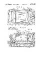
- FIG. 1is a diagrammatic side elevational view of a hair dryer, partially cut-away to show part of a magnetic switch (in phantom) constructed in accordance with the principles of this invention.
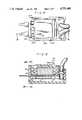
- FIG. 2is a cross-sectional view of FIG. 1 taken along the line 2--2 showing a magnetic switch constructed in accordance with the principles of this invention.
- FIG. 3is a plan view of the magnetic switch of FIG. 2.
- FIG. 4is a side elevational view of the magnetic switch of FIG. 3 taken along the lines 4--4 showing the switch in a closed position.
- FIG. 5is a side elevational view of the magnetic switch in an open position.
- FIG. 6is a right end elevational view of the switch taken along the lines 5--5 of FIG. 3.
- FIG. 7is a bottom plan view of a portion of FIG. 2 taken along the lines 7--7.
- FIG. 8is a plan view of an alternate embodiment of a magnetic switch.
- FIG. 9is a side elevational view of FIG. 8 taken along the lines 9--9.
- FIG. 10is a left side view of FIG. 9 taken along the lines 10--10.
- FIG. 11is a view similar to FIG. 9 but showing the switch in an open position.
- FIG. 12is a left end view of FIG. 11 taken along the lines 12--12 showing the magnetic switch in an open position.
- FIG. 13is an elevational view of yet another alternate embodiment of the magnetic switch.
- FIGS. 1 and 2there is shown an elevational cut-away view, and a cross-sectional view respectively of an electrical hand-held appliance 10 (in this case, a hair dryer).
- Appliance 10is provided with a pair of electrical power input lines 12, 14, slide switch caps 16 and 17 and a conventional power on/off switch 18.
- Magnetic switch 20, constructed in accordance with the principles of the invention,is interposed between power lines 12, 14 and power switch 18.
- Printed circuit board 19is connected to a magnetic switch 20 and to power switch 18 to accomodate some of the wiring connections in the appliance.
- cap 16when in the off position (at the bottommost point of its travel as viewed in FIG. 1) will, as will be understood below, disconnect electrical power from the appliance. As the cap 16 is moved upwardly, the magnetic switch will be closed while still enabling the appliance to be set in different modes, i.e. low and high. Additionally, cap 17 controls a separate switch 18a (only partially visible in FIG. 2) and is independently operable of cap 16 and its associated power switch 18.
- magnetic switch 20comprises a dual compartment housing 22 formed into a hermetically sealed lower compartment 24 and an adjacent open compartment 26. Compartments 24 and 26 are separated by a common dividing wall 28.
- Lower compartment 24includes a pair of terminals 30 and 32, each respectively connected to a power input line 12 and 14. Terminals 30 and 32 are at the bottom of respective apertures in insulating spacer block 33. Also connected to terminals 30 and 32 are the ends of leaf springs 34 and 36, the other ends of the leaf springs having attached thereto movable electrical contacts 38 and 40, respectively.
- Leaf springs 34 and 36are joined intermediate their ends by an insulated reinforcing member 42 secured to the bottom of the leaf springs. Member 42 serves to assure that contacts 34 and 36 move essentially simultaneously. This results in each contact 34 and 36 being randomly closed ahead of the other, thereby producing relatively even wear of each pair of contacts 38, 56 and 40, 58 (explained below). It is important that the contacts be adjusted to close essentially simultaneously to produce even wear. Otherwise, after repeated use the non-wearing pair of contacts would prevent the worn pair of contacts from closing.
- Each leaf springis also provided intermediate its ends with an armature or metallic plate 44 and 46 which, as will be understood below, serves to enhance the magnetic attraction of the leaf springs.
- the metallic plates 44 and 46 and the insulated member 42may be attached to the leaf springs by rivets 48 and 50 and/or spot welds 51 to limit rotation about the rivet point. It should be noted that metallic plates 44 and 46 are generally longitudinal and are attached to their respective leaf springs at only one end of the plates, the other end of the metallic plates, in the areas 52 and 54 are free to move away from the leaf springs as will be understood below.
- a pair of fixed electrical contacts 56 and 58which provide the mating surfaces for movable contacts 38 and 40 when magnetic switch 20 is in the closed position.
- Contacts 56 and 58each have extensions protruding through the front wall of housing 22 in order to connect the contacts to printed circuit board 19.
- the area over contacts 56 and 58is thicker than other parts of housing 22 in order to provide adequate insulation.
- a ramp member 60, situated under each leaf spring, and a separating wall 62are also molded into lower compartment 24, the purposes of which will be explained below.
- Compartment 26comprises a front wall 70, a pair of parallel side walls 72 and 74, each having at an intermediate point along its length raised ear portions 75 and 76, respectively.
- Rear wall 79is joined to the opposite ends of parallel walls 72 and 74 and an intermediate transverse wall 77 is situated therebetween.
- the walls 70, 72, 74 and 79are integrally formed with corresponding walls of lower compartment 24.
- Magnet holder 80Situated between parallel walls 72 and 74 is a magnet holder 80 holding a magnet 82 and a flux return plate 84.
- Magnet holder 80is a three sided structure having a front wall 90, top wall 92, and rear wall 94. Magnet 82 is adhesively or otherwise secured between front wall 90 and rear wall 94.
- the area bounded by rear wall 79, transverse wall 77, the intervening portions of side walls 72 and 74 and common separating wall 28is filled with epoxy or potting compound 81 around power lines 12 and 14 to provide spacing, alignment and insulation.
- the operation of the magnetic switchrequires a motion for magnet 82 which is provided by pivot pins 98 and 100 extending from the sides in or near rear wall 94 into apertures 102 and 104 formed into ears 75 and 76, respectively.
- Magnet 82is permitted to pivot about pins 98 and 100 between a closed position as shown in FIG. 4 where the bottom surface of magnet 82 lies on the top surface of common separating wall 28 and an open position as shown in FIG. 5.
- the magnetis held in a normally open position by biasing spring 110 which is interposed between the rear surface of magnet 82 and transverse wall 77 of compartment 26.
- Spring 110is, in the preferred embodiment, metallic and held in the loction by magnetic attraction.
- slide cap 16is provided with an extension 120 having a cam projection 122 normally resting within a recess 124 of the top surface 92 of magnet holder 80 (best seen in FIG. 5).
- Slide cap 16 and extension 120are limited to horizontal motion only in the direction of the arrows and it will, therefore, be understood that, as extension 120 and cam 122 are moved horizontally, cam 122 may rest in recess 124 to allow lift spring 110 to pivot the magnet away from separating wall 28 to open the switch, or cam 122 may ride on top surface 92 in order to exert downward pressure on the magnet holder to overcome the bias of lift spring 110 to move the magnet closer to separating wall 28.
- An additional feature of the inventionis provided by dividing wall 62 separating contact pairs 38, 56 and 40, 58 and portions of leaf springs 34 and 36 from each other. This extends the useful life of switch 20 by preventing carbon tracking due to arcing.
- metallic plates 44 and 46are only secured to leaf springs 34 and 36 at essentially one point.
- the front end of metallic plates 44 and 46 in the areas 52 and 54are left free to be displaced from their respective leaf springs as the plates are attracted flush against the bottom of wall 28.
- spacesmay exist in the areas 52 and 54 such that, given the natural bias of leaf springs 34 and 36, the force with which electrical contacts 38 and 40 press against their respective stationary contacts may vary.
- FIGS. 8 through 12show one alternate embodiment of the invention in the form of magnetic switch 220.
- FIG. 13shows yet another embodiment in the form of switch 320.
- the essential difference between previously described switch 20 and switches 220 and 320is in the area of the upper compartment 224 and components associated with the actuation of the magnet.
- Switch 220rather than incorporating a spring which biases the magnet in only one position, utilizes a W-shaped spring 210 which is mounted in an "over-center" configuration and serves to retain the magnet in either the open or the closed position.
- Spring 210is attached at each end 230 and 232 to the side walls of upper compartment 224.
- the center 240 of spring 210is received within a notch 250 provided in an extension 252 at the front end of magnet holder 282. It will be understood that as cam projection 222 is moved to the extreme right as seen in FIG. 11, it will push against an upward projection 260 of magnet holder 282 causing the magnet holder to pivot about its back edge 262.
- switch 320In addition to the alternate embodiment of switch 220, it will be noted by those skilled in the art that various other embodiments may be utilized to move the magnet and retain it in either the open or closed position.
- switch 320In FIG. 13. While most components of this switch are the same as those previously described, and are therefore not described or shown in detail, spring 310 is significantly different.
- Spring 310comprises a part 312 secured to the front of upper compartment 324 and an abutting part 314 secured to the front of magnet holder 380. Each part 312 and 314 has a predetermined width along the abutting surfaces and is uniquely shaped to provide an over-center action to retain magnet 382 either open or closed.
- switch 20is provided with a "fail-safe" mechanism which is not provided by switches 220 and 320.
- spring 110will very quickly open the switch because of the normally open bias.
- Switches 220 and 320since they are designed with springs that move the magnet to either one of two positions when a certain amount of force is applied to the springs, may, if the appliance is dropped, cause the magnet to move and stay in an undesired position. Additional locking means would need to be incorproated to overcome this.
Landscapes
- Push-Button Switches (AREA)
- Switches That Are Operated By Magnetic Or Electric Fields (AREA)
- Switches With Compound Operations (AREA)
- Switch Cases, Indication, And Locking (AREA)
- Keying Circuit Devices (AREA)
Abstract
Description
Claims (13)
Priority Applications (12)
| Application Number | Priority Date | Filing Date | Title |
|---|---|---|---|
| US07/084,585US4751485A (en) | 1987-08-12 | 1987-08-12 | Waterproof switch assembly for electrical appliances |
| US07/173,701US4879443A (en) | 1987-08-12 | 1988-03-25 | Waterproof switch assembly for electrical appliances |
| ZA885679AZA885679B (en) | 1987-08-12 | 1988-08-03 | Waterproof switch assembly for electrical appliances |
| CA 574308CA1292490C (en) | 1987-08-12 | 1988-08-10 | Waterproof switch assembly for electrical appliances |
| DE19883827306DE3827306A1 (en) | 1987-08-12 | 1988-08-11 | WATERPROOF SWITCHING DEVICE FOR ELECTRICAL SYSTEMS |
| SE8802875ASE8802875L (en) | 1987-08-12 | 1988-08-11 | THE WATER NETWORK REPLACEMENT UNIT FOR ELECTRICAL APPLIANCES |
| FR8810821AFR2623325A1 (en) | 1987-08-12 | 1988-08-11 | ELECTRICAL SWITCH ASSEMBLY FOR ELECTRICAL APPLIANCES |
| IT2169988AIT1226843B (en) | 1987-08-12 | 1988-08-11 | WATERPROOF SWITCH COMPLEX FOR ELECTRICAL APPLIANCES |
| GB8819139AGB2208565B (en) | 1987-08-12 | 1988-08-11 | Electrical switch assembly and appliances containing same |
| DK450188ADK450188A (en) | 1987-08-12 | 1988-08-11 | ELECTRICAL CONTACT |
| CN88104954ACN1035582A (en) | 1987-08-12 | 1988-08-12 | The water-proof switch device of using for electric power tool |
| JP20029888AJPS6465738A (en) | 1987-08-12 | 1988-08-12 | Moisture-proof switch assembly for electric appliance |
Applications Claiming Priority (1)
| Application Number | Priority Date | Filing Date | Title |
|---|---|---|---|
| US07/084,585US4751485A (en) | 1987-08-12 | 1987-08-12 | Waterproof switch assembly for electrical appliances |
Related Child Applications (1)
| Application Number | Title | Priority Date | Filing Date |
|---|---|---|---|
| US07/173,701DivisionUS4879443A (en) | 1987-08-12 | 1988-03-25 | Waterproof switch assembly for electrical appliances |
Publications (1)
| Publication Number | Publication Date |
|---|---|
| US4751485Atrue US4751485A (en) | 1988-06-14 |
Family
ID=22185913
Family Applications (1)
| Application Number | Title | Priority Date | Filing Date |
|---|---|---|---|
| US07/084,585Expired - Fee RelatedUS4751485A (en) | 1987-08-12 | 1987-08-12 | Waterproof switch assembly for electrical appliances |
Country Status (11)
| Country | Link |
|---|---|
| US (1) | US4751485A (en) |
| JP (1) | JPS6465738A (en) |
| CN (1) | CN1035582A (en) |
| CA (1) | CA1292490C (en) |
| DE (1) | DE3827306A1 (en) |
| DK (1) | DK450188A (en) |
| FR (1) | FR2623325A1 (en) |
| GB (1) | GB2208565B (en) |
| IT (1) | IT1226843B (en) |
| SE (1) | SE8802875L (en) |
| ZA (1) | ZA885679B (en) |
Cited By (11)
| Publication number | Priority date | Publication date | Assignee | Title |
|---|---|---|---|---|
| US4833283A (en)* | 1987-02-09 | 1989-05-23 | Andis Company | Hand-held blower with interior waterproof switch assembly |
| US20040041684A1 (en)* | 2002-08-29 | 2004-03-04 | Mandell Joan Golden | Proximity safety switch suitable for use in a hair dryer for disabling operation |
| US20040040948A1 (en)* | 2002-08-29 | 2004-03-04 | Mandell Joan Golden | Proximity safety switch suitable for use in a hair dryer for disabling operation |
| US20040171912A1 (en)* | 2003-02-27 | 2004-09-02 | Olympus Corporation | Operating mechanism for medical device |
| US20090072936A1 (en)* | 2007-04-23 | 2009-03-19 | Kabushiki Kaisha Tokai Rika Denki Seisakusho | Switching device |
| US20100188178A1 (en)* | 2007-07-24 | 2010-07-29 | Min-Chin Chen | Magnetic waterproof switch assembly |
| US20110103627A1 (en)* | 2008-10-03 | 2011-05-05 | Meier Roger S | Sound processors and implantable cochlear stimulation systems including the same |
| US8437860B1 (en) | 2008-10-03 | 2013-05-07 | Advanced Bionics, Llc | Hearing assistance system |
| US9491530B2 (en) | 2011-01-11 | 2016-11-08 | Advanced Bionics Ag | Sound processors having contamination resistant control panels and implantable cochlear stimulation systems including the same |
| EP3878307A3 (en)* | 2020-03-12 | 2021-11-10 | Shenzhen Airgle Corporation Limited | Hair dryer |
| US11253038B2 (en) | 2020-03-12 | 2022-02-22 | Shenzhen Airgle Corporation Limited | Hair dryer |
Families Citing this family (3)
| Publication number | Priority date | Publication date | Assignee | Title |
|---|---|---|---|---|
| US6269529B2 (en)* | 1999-08-18 | 2001-08-07 | Thomas R. Clark | Hose preparation apparatus and method therefor |
| CN109527763B (en)* | 2018-12-17 | 2024-04-12 | 追觅科技(苏州)有限公司 | Switch of hair dryer and hair dryer |
| JP7190707B2 (en)* | 2020-03-12 | 2022-12-16 | 深▲せん▼奥郎格環保有限公司 | Hair Dryer |
Citations (5)
| Publication number | Priority date | Publication date | Assignee | Title |
|---|---|---|---|---|
| US1958482A (en)* | 1932-07-28 | 1934-05-15 | Milwaukee Gas Specialty Co | Magnetic switch |
| US3689859A (en)* | 1971-03-22 | 1972-09-05 | E R Carl Straub | Reed switch |
| US4150350A (en)* | 1976-12-16 | 1979-04-17 | Fong Lee W | Magnetic switch |
| US4464582A (en)* | 1982-10-12 | 1984-08-07 | Tsunehide Aragaki | Water-safe hair dryer circuit |
| US4589047A (en)* | 1982-03-06 | 1986-05-13 | Gaues Harry | Protective mechanism in electrically operated devices |
Family Cites Families (6)
| Publication number | Priority date | Publication date | Assignee | Title |
|---|---|---|---|---|
| GB987935A (en)* | 1962-01-15 | 1965-03-31 | Robertshaw Fulton Controls Co | Improvements in magnetically actuated electric switches |
| DE1900973A1 (en)* | 1968-01-09 | 1969-07-31 | Fujitsu Ltd Comm And Electroni | Slide switch |
| GB1227835A (en)* | 1968-11-04 | 1971-04-07 | ||
| DE7813109U1 (en)* | 1976-12-16 | 1979-05-31 | Fong, Lee Wen, Taichung (China/ Taiwan) | Magnetic switch |
| GB8416615D0 (en)* | 1984-06-29 | 1984-08-01 | Sonca Ind Ltd | Electric lighting devices |
| DD247102B5 (en)* | 1986-02-25 | 1993-07-15 | Efn Entwicklungsgesellschaft F | TUBE CONTACT BUTTON |
- 1987
- 1987-08-12USUS07/084,585patent/US4751485A/ennot_activeExpired - Fee Related
- 1988
- 1988-08-03ZAZA885679Apatent/ZA885679B/enunknown
- 1988-08-10CACA 574308patent/CA1292490C/ennot_activeExpired - Fee Related
- 1988-08-11DKDK450188Apatent/DK450188A/ennot_activeApplication Discontinuation
- 1988-08-11ITIT2169988Apatent/IT1226843B/enactive
- 1988-08-11DEDE19883827306patent/DE3827306A1/ennot_activeCeased
- 1988-08-11FRFR8810821Apatent/FR2623325A1/ennot_activeWithdrawn
- 1988-08-11GBGB8819139Apatent/GB2208565B/ennot_activeExpired - Lifetime
- 1988-08-11SESE8802875Apatent/SE8802875L/ennot_activeApplication Discontinuation
- 1988-08-12JPJP20029888Apatent/JPS6465738A/enactivePending
- 1988-08-12CNCN88104954Apatent/CN1035582A/enactivePending
Patent Citations (5)
| Publication number | Priority date | Publication date | Assignee | Title |
|---|---|---|---|---|
| US1958482A (en)* | 1932-07-28 | 1934-05-15 | Milwaukee Gas Specialty Co | Magnetic switch |
| US3689859A (en)* | 1971-03-22 | 1972-09-05 | E R Carl Straub | Reed switch |
| US4150350A (en)* | 1976-12-16 | 1979-04-17 | Fong Lee W | Magnetic switch |
| US4589047A (en)* | 1982-03-06 | 1986-05-13 | Gaues Harry | Protective mechanism in electrically operated devices |
| US4464582A (en)* | 1982-10-12 | 1984-08-07 | Tsunehide Aragaki | Water-safe hair dryer circuit |
Cited By (21)
| Publication number | Priority date | Publication date | Assignee | Title |
|---|---|---|---|---|
| US4833283A (en)* | 1987-02-09 | 1989-05-23 | Andis Company | Hand-held blower with interior waterproof switch assembly |
| US20040041684A1 (en)* | 2002-08-29 | 2004-03-04 | Mandell Joan Golden | Proximity safety switch suitable for use in a hair dryer for disabling operation |
| US20040040948A1 (en)* | 2002-08-29 | 2004-03-04 | Mandell Joan Golden | Proximity safety switch suitable for use in a hair dryer for disabling operation |
| US6750747B2 (en)* | 2002-08-29 | 2004-06-15 | Ljm Associates, Inc. | Proximity safety switch suitable for use in a hair dryer for disabling operation |
| WO2004019721A3 (en)* | 2002-08-29 | 2004-07-08 | Ljm Associates Inc | Proximity safety switch suitable for use in a hair dryer for disabling operation |
| US6784775B2 (en) | 2002-08-29 | 2004-08-31 | Ljm Associates, Inc. | Proximity safety switch suitable for use in a hair dryer for disabling operation |
| US20050011879A1 (en)* | 2002-08-29 | 2005-01-20 | Mandell Joan Golden | Proximity safety switch suitable for use in a hair dryer for disabling operation |
| US7002442B2 (en) | 2002-08-29 | 2006-02-21 | Ljm Associates, Inc. | Proximity safety switch suitable for use in a hair dryer for disabling operation |
| US20040171912A1 (en)* | 2003-02-27 | 2004-09-02 | Olympus Corporation | Operating mechanism for medical device |
| US7278965B2 (en)* | 2003-02-27 | 2007-10-09 | Olympus Corporation | Operating mechanism for medical device |
| US20090072936A1 (en)* | 2007-04-23 | 2009-03-19 | Kabushiki Kaisha Tokai Rika Denki Seisakusho | Switching device |
| US7750771B2 (en)* | 2007-04-23 | 2010-07-06 | Kabushiki Kaisha Tokai Rika Denki Seisakusho | Switching device |
| US20100188178A1 (en)* | 2007-07-24 | 2010-07-29 | Min-Chin Chen | Magnetic waterproof switch assembly |
| US20110103627A1 (en)* | 2008-10-03 | 2011-05-05 | Meier Roger S | Sound processors and implantable cochlear stimulation systems including the same |
| US8437860B1 (en) | 2008-10-03 | 2013-05-07 | Advanced Bionics, Llc | Hearing assistance system |
| US8750546B2 (en) | 2008-10-03 | 2014-06-10 | Advanced Bionics | Sound processors and implantable cochlear stimulation systems including the same |
| US9294852B2 (en) | 2008-10-03 | 2016-03-22 | Advanced Bionics Ag | Sound processors and implantable cochlear stimulation systems including the same |
| US9491530B2 (en) | 2011-01-11 | 2016-11-08 | Advanced Bionics Ag | Sound processors having contamination resistant control panels and implantable cochlear stimulation systems including the same |
| US9609444B2 (en) | 2011-01-11 | 2017-03-28 | Advanced Bionics Ag | Sound processors having contamination resistant control panels and implantable cochlear stimulation systems including the same |
| EP3878307A3 (en)* | 2020-03-12 | 2021-11-10 | Shenzhen Airgle Corporation Limited | Hair dryer |
| US11253038B2 (en) | 2020-03-12 | 2022-02-22 | Shenzhen Airgle Corporation Limited | Hair dryer |
Also Published As
| Publication number | Publication date |
|---|---|
| CN1035582A (en) | 1989-09-13 |
| JPS6465738A (en) | 1989-03-13 |
| GB8819139D0 (en) | 1988-09-14 |
| GB2208565A (en) | 1989-04-05 |
| DK450188D0 (en) | 1988-08-11 |
| IT1226843B (en) | 1991-02-19 |
| SE8802875L (en) | 1989-02-13 |
| DK450188A (en) | 1989-02-13 |
| GB2208565B (en) | 1992-01-15 |
| IT8821699A0 (en) | 1988-08-11 |
| DE3827306A1 (en) | 1989-02-23 |
| FR2623325A1 (en) | 1989-05-19 |
| SE8802875D0 (en) | 1988-08-11 |
| ZA885679B (en) | 1989-04-26 |
| CA1292490C (en) | 1991-11-26 |
Similar Documents
| Publication | Publication Date | Title |
|---|---|---|
| US4879443A (en) | Waterproof switch assembly for electrical appliances | |
| US4751485A (en) | Waterproof switch assembly for electrical appliances | |
| US4595894A (en) | Ground fault circuit interrupting system | |
| KR101016212B1 (en) | Micro switch | |
| DE59401649D1 (en) | Temperature-dependent switch | |
| KR890007182Y1 (en) | Micro switch | |
| JPS63202816A (en) | Remotely controllable protection switch gear | |
| WO1995004364A3 (en) | Improvements relating to electric switches | |
| GB2185855A (en) | Switch construction with multiple contact sets | |
| US4559510A (en) | Equipment protecting electrical circuit breaker | |
| US3978303A (en) | Leaf spring switch | |
| US5601183A (en) | Two-pole make-before-break switch | |
| US5124679A (en) | Automatic power breaker and relay and water sensor used in the automatic power breaker | |
| RU95116369A (en) | BRIDGE CONTACT SWITCH | |
| US4288767A (en) | Automatic magnetic switch | |
| ES1032243U (en) | Thermally controlled electrical switching device having a snap-action switch | |
| DE59609050D1 (en) | Switch with a switching mechanism that switches in the event of overtemperature | |
| US4454400A (en) | Switch construction | |
| US3261937A (en) | Three position snap switch utilizing interference blade means | |
| US3311716A (en) | Snap-action sequential multi-circuit switch | |
| US4482875A (en) | Polarized electromagnetic midget relay | |
| US4348563A (en) | Snap action switches | |
| US3432782A (en) | Pushbutton-controlled overload circuit breaker | |
| US4209677A (en) | Precision snap switch with improved one piece contact support and terminal member | |
| JPS6046503B2 (en) | circuit break |
Legal Events
| Date | Code | Title | Description |
|---|---|---|---|
| AS | Assignment | Owner name:CLAIROL INCORPORATED, 345 PARK AVE. NEW YORK, NY 1 Free format text:ASSIGNMENT OF ASSIGNORS INTEREST.;ASSIGNORS:FUJIO, ATSUSHI;CARLUCCI, VITO;KUNZ, RAYMOND;REEL/FRAME:004821/0166;SIGNING DATES FROM 19871010 TO 19871113 Owner name:CLAIROL INCORPORATED, A CORP. OF DE,NEW YORK Free format text:ASSIGNMENT OF ASSIGNORS INTEREST;ASSIGNORS:FUJIO, ATSUSHI;CARLUCCI, VITO;KUNZ, RAYMOND;SIGNING DATES FROM 19871010 TO 19871113;REEL/FRAME:004821/0166 | |
| FPAY | Fee payment | Year of fee payment:4 | |
| AS | Assignment | Owner name:REMINGTON PRODUCTS COMPANY, CONNECTICUT Free format text:ASSIGNMENT OF ASSIGNORS INTEREST;ASSIGNOR:CLAIROL INCORPORATED;REEL/FRAME:006842/0900 Effective date:19931224 Owner name:PROVIDENT BANK, AGENT, THE, OHIO Free format text:SECURITY INTEREST;ASSIGNOR:REMINGTON PRODUCTS COMPANY;REEL/FRAME:006842/0702 Effective date:19931224 | |
| REMI | Maintenance fee reminder mailed | ||
| AS | Assignment | Owner name:REMINGTON PRODUCTS COMPANY, CONNECTICUT Free format text:RELEASE BY SECURED PARTY;ASSIGNOR:PROVIDENT BANK, THE;REEL/FRAME:007991/0223 Effective date:19960523 | |
| LAPS | Lapse for failure to pay maintenance fees | ||
| FP | Lapsed due to failure to pay maintenance fee | Effective date:19960619 | |
| STCH | Information on status: patent discontinuation | Free format text:PATENT EXPIRED DUE TO NONPAYMENT OF MAINTENANCE FEES UNDER 37 CFR 1.362 |