US4749069A - Vibration damper for motor vehicles having an arrangement for varying damping thereof - Google Patents
Vibration damper for motor vehicles having an arrangement for varying damping thereofDownload PDFInfo
- Publication number
- US4749069A US4749069AUS06/915,265US91526586AUS4749069AUS 4749069 AUS4749069 AUS 4749069AUS 91526586 AUS91526586 AUS 91526586AUS 4749069 AUS4749069 AUS 4749069A
- Authority
- US
- United States
- Prior art keywords
- damping
- section
- flow cross
- vibration damper
- valve
- Prior art date
- Legal status (The legal status is an assumption and is not a legal conclusion. Google has not performed a legal analysis and makes no representation as to the accuracy of the status listed.)
- Expired - Fee Related
Links
Images


Classifications
- F—MECHANICAL ENGINEERING; LIGHTING; HEATING; WEAPONS; BLASTING
- F16—ENGINEERING ELEMENTS AND UNITS; GENERAL MEASURES FOR PRODUCING AND MAINTAINING EFFECTIVE FUNCTIONING OF MACHINES OR INSTALLATIONS; THERMAL INSULATION IN GENERAL
- F16F—SPRINGS; SHOCK-ABSORBERS; MEANS FOR DAMPING VIBRATION
- F16F9/00—Springs, vibration-dampers, shock-absorbers, or similarly-constructed movement-dampers using a fluid or the equivalent as damping medium
- F16F9/32—Details
- F16F9/44—Means on or in the damper for manual or non-automatic adjustment; such means combined with temperature correction
- F16F9/46—Means on or in the damper for manual or non-automatic adjustment; such means combined with temperature correction allowing control from a distance, i.e. location of means for control input being remote from site of valves, e.g. on damper external wall
Definitions
- the inventionrelates generally to an arrangement for varying the damping of a piston in hydraulic, pneumatic or hydro-pneumatic assemblies, such as vibration dampers, gas springs and hydro-pneumatic suspensions and, more particularly, to vibration dampers having the piston arranged to slide axially by means of a piston rod in a cylinder filled with at least one damping medium.
- the prior artincludes hydraulic shock absorbers, such as those disclosed in Federal Republic of Germany Patent Publication Published for Opposition Purposes No. DE-AS 12 42 945 and No. DE-AS 14 05 781, and French Patent No FR-PS 11 75 293, whose damping characteristics can be adjusted electromagnetically by changing the flow of the hydraulic damping medium through the damping valves.
- there are two bypass connectionsthe first of which generally serves to regulate the damping force in the decompression stage in relation to the compression stage.
- To change the damping force to suit different road conditionsthere is an additional bypass connection in the decompression stage, in which there is an electromagnetically-controlled valve.
- a disadvantage of this arrangementis that there is no way to control the damping force in the compression stage.
- an electromagnetwhich can be turned either on or off, it is only possible to achieve a corresponding upper and lower damping force curve. In these systems, it is impossible to achieve intermediate values.
- the prior artalso includes hydraulic adjustable shock absorbers, such as in Federal Republic of Germany Laid Open Patent Application No. DE-OS 21 19 531, in which there is a first damping element and also a line equipped with a control valve. A control valve and a damping element are located separately in a closed loop. The setting of the control valve is done either manually or by the action of one of the vehicle mechanisms.
- a disadvantage of this arrangementis that when the control valve is activated, it is again only possible to achieve an upper and a lower damping force curve, whereby any damping values which may be desired between these two limit values cannot be achieved merely by turning on and off the control valve. Beyond the specified limits, there is no variability.
- the above-cited patent publicationsare incorporated herein by reference as if the contents thereof were fully set forth herein.
- the object of the inventionis to control and activate the bypass valve of a shock absorber electronically, so that a desired, variable damping force can be produced both in the decompression and also in the compression stage between two fixed fundamental curves by means of the current sent to the electromagnet, and whereby, in addition, brief switching intervals are assured by the configuration of the valve body.
- the inventive embodimentspropose that the damping force, between an upper limit when the damping valve is not energized and a lower limit when the damping valve is energized, can be adjusted by the selection of a pulse width repetition rate and that the damping force is equal to the upper damping force minus the difference between the upper damping force and the lower damping force, multiplied by the pulse width repetition rate.
- the systemcomprises at least one hydraulic, adjustable shock absorber which, by means of a work piston fastened to a piston rod, divides the work cylinder into two work chambers filled with damping fluid.
- a damping valvelocated in a bypass, comprising of an axially-movable, controllable valve body working together with a passage, exhibiting an electromagnet and activated by a suitable electronic system.
- the shock absorberproduces an upper or lower damping force in relation to the current piston velocity.
- An advantage with this configurationis that a damping force adjustment is achieved by modulation of the duration of the energization pulse in the bypass channel.
- the damping forcecan be effectively varied between two fixed defined fundamental curves.
- the fundamental curves of the damping forceare thereby determined by the mechanical components, such as the damping valves and the cross section of the bypass.
- the pulse width repetition rateis thereby the ratio between the time the electromagnet is energized and a constant time period.
- a pulse width repetition rate of 50%is required, that is, within a determined time constant, the valve body will remain open one-half of the time, and must remain closed the other half of the time.
- the adjustment precision for the effective desired damping rate lying between the limit valuesis thereby a function of the level of the clock frequency of the circuit connected to and controlling the electromagnet. In other words, there must be an appropriate resolution and, consequently, the smaller the time constant which is selected and which can be put to practical use, the better the resolution which can be achieved.
- damping valvesthere are at least two damping valves in parallel in the bypass.
- Such an arrangementhas the advantage of reducing the damping force discontinuity between the upper and lower limit values.
- the regulating field which can be influenced by the pulse width modulationcan be divided into three partial fields, each with reduced damping force discontinuities.
- the three regulating fieldsare produced by the four possible damping force curves.
- These four damping force curvesresult from the possible combinations of positions of the two damping valves, whereby, for example, two valve bodies can be closed, the first valve open and the second valve closed, the second valve open and the first valve closed, and, as a fourth possibility, the two valve bodies of both damping valves can be open.
- the corresponding damping force curvesare achieved, so that damping forces are achieved in these three individual regulating fields by activating one or both of the valves simultaneously.
- the valve bodyexhibits a small sealing surface.
- a particularly advantageous embodimentprovides that the inside diameter of the sealing surface is smaller than the outside diameter of the valve body.
- the outside diameter of the sealing surfacecan also be larger than the outside diameter of the valve body.
- An advantage hereis that a stable closing position of the damping valve is achieved, assisted to a minor extent by the closed position of the damping valve.
- the pressure determined by the damping valve of the bypassacts via the external surface of the valve body, and thus assists the closing process of the valve body.
- the geometric ratios of the valve bodymean that very brief switching intervals are possible. By harmonizing the partial surfaces of the entire valve body sealing surface, it becomes possible to exercise a hydraulically favorable action on the switching times. This hydraulic assist also makes possible the use of a valve body return spring with very low return forces. The available magnetic force on the armature of the electromagnet which controls the damping valve can therefore be increased, which is important for the switching interval of the electromagnet.
- the dampercomprises a cylinder assembly having an arrangement for varying damping of a piston assembly disposed therein.
- the piston assemblydivides the cylinder into at least two chambers, each for containing damping fluid.
- the vibration dampercomprises an apparatus for throttling the damping fluid when the damping fluid moves from one of the chambers into another.
- the piston assemblyhas a piston rod and piston.
- the piston rodhas a first apparatus for attachment of the piston rod at one end thereof.
- the cylinder assemblyhas a second apparatus for attachment at a portion thereon other than the first apparatus for attachment at the piston rod.
- the vibration damperhas an apparatus for bypassing damping fluid and an arrangement for accepting bypassed damping fluid.
- the bypassing apparatusis disposed to bypass the damping fluid from one of the damping fluid-containing chambers to the accepting arrangement.
- the bypassing apparatusincludes a damping valve arrangment for regulating flow of the damping fluid in the bypassing apparatus.
- the valvingincludes an electromagnetically-displaceable component for effecting a first flow cross section and a second flow cross section in the valving.
- An electromagnetvaries the cross section flow of the valving between the first and second flow cross sections by displacing the electromagnetically-displaceable component.
- the electromagnethas an arrangement for connection to electronic controlling apparatus.
- the electronic controlling apparatuscomprises an arrangement for generating an electrical signal which is repetitive and has a variable pulse width.
- the arrangement for generatingprovides a signal to vary the cross section of the flow cross section of the valving periodically, whereby a damping on the piston assembly provides a damping between the damping produced by the first flow cross section and the damping produced by the second flow cross section.
- An embodiment of the inventionincludes a cylinder assembly.
- An electrical signal generating meansincludes circuitry for generating a repetitive pulse of a given frequency and circuitry for varying an on-time of the pulse, thereby producing a damping force (Fx) on the piston assembly which can be adjusted by selecting the pulse width repetition rate (Tv) between an upper force (Fo) when the damping valve is not energized, and a lower force (Fu) when the damping valve is always energized, and that the damping force (Fx) is equal to the upper damping force (Fo x ) minus the difference between the upper damping force (Fo x ) and the lower damping force (Fu x ), multiplied by the pulse width repetition rate (Tv).
- FIG. 1shows a hydraulic shock absorber with a damping valve, in partial cross section
- FIG. 2shows a damping valve with an electromagnet in section, and in detail
- FIG. 3shows a force-velocity diagram of an adjustable shock absorber with a bypass valve
- FIG. 4is the diagram of a damping force action at the point Vx (piston velocity);
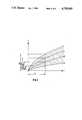
- FIG. 5is another force-velocity diagram with four different fundamental curves and, in relation to them, three corresponding partial regulating fields.
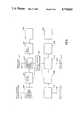
- FIG. 6shows a circuit for the operation of the electromagnets of the damping valve according to an embodiment of the invention.
- FIG. 7shows the hydraulic shock absorber of FIG. 1 with two damping valves.
- the vibration damping system illustrated in FIG. 1is a shock absorbing strut in a double-tube model.
- the shock-absorbing strut 1 illustrated in FIG. 1consists essentially of the work piston 2, the piston rod 3 and the work cylinder 4.
- the work piston 2divides the work cylinder 4 into the upper work chamber 5 and the lower work chamber 6.
- the work piston 2is also equipped with damping valves (not shown) which are well known in the prior art. In the floor of the work cylinder 4, there are other valves, over whose cross sections the volume displaced by the piston rod 3 is displaced into the equalization chamber 16.
- the equalization chamber 16is formed by the wall of the work cylinder 4 and the inside wall of a jacket 17.
- FIG. 2shows a detail of a damping valve 7 whereby, starting from a bypass channel 8, the damping fluid travels through a passage 9, past a valve body 10, via borings 19 on a spring washer valve 20 into an equalization chamber 16.
- the valve body 10is also the armature for an electromagnet 11.
- the valve body 10is equipped, on its side facing the passage 9, with a sealing surface 12, which seals it against the passage 9.
- the boring 21 of the valve body 10assures that, on the back side of the valve body 10, an appropriate work pressure is accumulated on an end surface 22.
- the sealing surface 12 of the valve body 10exhibits an inside diameter 13, the surface of which is smaller than the end surface of the end 22, so that the work pressure of the shock absorber exerts a slight auxiliary closing force on the valve body 10.
- the pressure determined by the damping valve 20 of the bypass valveacts via the surface formed by an outside diameter 14 and 15 of the valve body 10 as an auxiliary force on the closing process of the valve body 10 of the damping valve 7.
- FIG. 3is a force-velocity diagram of the shock-absorbing strut illustrated in FIG. 1.
- the damping forceis plotted in relation to the piston velocity.
- Curve Irepresents the damping curve when the valve body 10 is closed.
- Curve IIrelates to the open valve body. Between the Curve I and the Curve II, there is a regulating field, which covers damping forces which can be achieved when the electromagnet 11 is correspondingly activated. If, for example, the damping force Fx is achieved at a piston velocity Vx, then a corresponding pulse width repetition rate is to be set, as shown in FIG. 4.
- FIG. 4shows one example for influencing the damping force at point Vx. It has been assumed, to make the diagram easier to understand, that Vx is constant over a rather long period of time t.
- the damping force curve Fo xis a point from the fundamental Curve I in FIG. 3.
- the damping force Fu xrepresents, at the same point Vx, a point of the fundamental Curve II of the curve shown in FIG. 3.
- the pulse width repetition rateis an important criterion.
- the pulse width repetition rateis defined as:
- the fundamental Curve IWith a pulse width repetition rate of 100%, the fundamental Curve I is reached, since the bypass via the valve body 10 is closed.
- the closing timeis specified at 100% during a time constant (to). If, at a pulse width repetition rate of 0, the bypass 8 via the valve body 10 is opened for the entire time of the time constant (to), then the lower fundamental Curve II applies. Now, if for example, a geometric mean value is achieved exactly halfway between the upper fundamental Curve I and the lower fundamental Curve II, then a pulse width repetition rate of 50% is necessary. With a pulse width repetition rate of 50%, one-half of the time constant (to), the valve body 10 is closed, and the other one-half of the time constant, it is open.
- FIG. 4shows hat the damping force Fx can be varied between Fo x and Fu x as a function of the selection of the pulse width repetition rate Tv.
- the variationfollows the formula:
- Tvpulse width repetition rate
- any other desired curve between these extreme fundamental curvescan be achieved, by solving the formula for the pulse width repetition rate, and using the corresponding value to control the electromagnet 11. It can be seen that the regulating precision for the electromagnet for the value lying between the upper and the lower limit of the effective damping force Fx is a function of the level of the clock frequency of the electromagnet.
- the force-velocity diagram shown in FIG. 5includes curves which are obtained when, for example, two damping valves 7 are used.
- the goal of this applicationis to reduce the damping force discontinuity between Fo and Fu.
- the regulating field which can be affected by pulse width modulationcan be divided into three partial fields, with reduced damping force discontinuities.
- the damping force fundamental Curves I to IVare achieved, as a function of the switching combination of the damping valves 7.
- both valve bodies 10are closed.
- the fundamental Curve IIshows a first valve body 10 open and the second valve body closed.
- the fundamental Curve IIIshows that the second valve body 10 is open and the first valve body, on the other hand, is closed.
- both valve bodies 10are opened. This switching combination yields the ability to vary the curves in the individual partial regulating fields.
- the partial regulating field 1is covered by electronic activation of the electromagnet 11 of the first damping valve 7, while the second damping valve 7 remains closed.
- the partial regulating field 2covers situations in which both damping valves 7 are operated by means of their electromagnets 11, whereby the signals run inverse to one another.
- the second damping valve 7is open, while the first damping valve 7 acts via its electromagnet on the valve body 10.
- the desired damping force Fx at the velocity Vxis achieved via the above-mentioned formula:
- the setting of the damping forcesis therefore always guaranteed in a partial regulating field, and extreme damping force discontinuities can thereby be avoided.
- FIG. 6shows a circuit for the operation of the electromagnets 11 of the valve body 10.
- two separate electromagnets 11a and 11bare shown, each being associated with a different valve body 10.
- the circuitry as shown in FIG. 6operates, it corresponds to the operation which has been described hereinabove related to FIG. 5. If only one valve body 10 with a single electromagnet 11 is to be used, only one of the two circuits shown in FIG. 6 need be used.
- an electromagnet 11ais connected to a power circuit 110, which provides the voltage pulses for the activation of electromagnet 11a in accordance with the operation as shown in FIG. 4.
- the power circuit 110is controlled by an adjustable pulse width circuit 112, which provides signals for the turning on and turning off of the power circuit 110, thereby providing the voltage pulses to the electromagnet 11a.
- the voltage pulses from the power circuit 110may also be current pulses or a combination of current and voltage pulses.
- the pulse width of the adjustable pulse width circuit 112is adjusted by an external signal which may enter preferably at a terminal 114 of the adjustable pulse width circuit 112.
- a clock circuit 116is connected to the adjustable pulse width circuit 112 in order to provide a clock pulse for the adjustable pulse width circuit 112 for the starting of each and every pulse, preferably.
- a clock adjustment circuit 118is connected to the clock circuit 116, whereby the clock frequency may be altered depending upon the desires of the driver of the motor vehicle having the vibrational damping system of the present invention, or depending upon other sensors which are described in U.S. Pat. Nos. 4,577,509; 4,587,850; application Ser. Nos.
- Circuits analogous to the circuits 110 through 118may be connected to a second electromagnet 11b of the second valve body 10. These circuits which are designated by the reference numerals 110b through 118b, correspond to the circuits as originally described above with regard to the circuits connected to the electromagnet 11a. There also may be interconnections between the adjustable pulse width circuits in order that both electromagnets do not open up simultaneously, or that under special conditions, they will open up simultaneously. Additional circuits such as a pulse width adjustment signal at 114 and 114b may be interconnected so that the pulse widths of each electromagnet 11a and 11b are different.
- the clock circuitsmay wish to have different clock period starting times in order that not both of the electromagnets 11a and 11b open up and close simultaneously for which purpose a non-coincidence circuit 122 is preferably provided, which is preferably connected to the clock circuits 116 and 116b and to the adjustable pulse width circuits 112 and 112b whereby the initial edges of the pulses are non-coincident with one another.
- the non-coincidence circuit 122can also adjust the falling edge of the pulses to assure non-coincidence of these as well.
- one set of circuits 110 through 118 or 110b through 118bmay be shut down and only one set may be activated. In the event that only one electromagnet is used in an installation, only one set of circuits 110 through 118 need be provided.
- the shock absorber strut 1(illustrated in FIG. 1) is shown with a first damping valve 7a and a second damping valve 7b connected thereto.
- the damping valves 7a and 7b, each having an electromagnet 11a and 11b corresponding to those in FIG. 6,are substantially identical to the damping valve 7 shown in FIG. 1.
Landscapes
- Engineering & Computer Science (AREA)
- General Engineering & Computer Science (AREA)
- Mechanical Engineering (AREA)
- Vehicle Body Suspensions (AREA)
- Fluid-Damping Devices (AREA)
Abstract
Description
Tv=ta/to
Tv (%)=ta/to·100
Fx=Fo.sub.x -(Fo.sub.x -Fu.sub.x)·Tv
Fx=Fo.sub.x -(Fo.sub.x -Fu.sub.x)·Tv
Claims (18)
Applications Claiming Priority (2)
| Application Number | Priority Date | Filing Date | Title |
|---|---|---|---|
| DE19853535287DE3535287A1 (en) | 1985-10-03 | 1985-10-03 | VIBRATION DAMPING SYSTEM FOR VEHICLES |
| DE3535287 | 1985-10-03 |
Related Child Applications (2)
| Application Number | Title | Priority Date | Filing Date |
|---|---|---|---|
| US07/036,307Continuation-In-PartUS4785920A (en) | 1986-04-16 | 1987-04-09 | Hydraulic adjustable shock absorber |
| US07/176,640Continuation-In-PartUS4850460A (en) | 1987-04-13 | 1988-04-01 | Hydraulic adjustable shock absorber |
Publications (1)
| Publication Number | Publication Date |
|---|---|
| US4749069Atrue US4749069A (en) | 1988-06-07 |
Family
ID=6282642
Family Applications (1)
| Application Number | Title | Priority Date | Filing Date |
|---|---|---|---|
| US06/915,265Expired - Fee RelatedUS4749069A (en) | 1985-10-03 | 1986-10-03 | Vibration damper for motor vehicles having an arrangement for varying damping thereof |
Country Status (6)
| Country | Link |
|---|---|
| US (1) | US4749069A (en) |
| JP (1) | JPS6283208A (en) |
| BR (1) | BR8603791A (en) |
| DE (1) | DE3535287A1 (en) |
| FR (1) | FR2588343B1 (en) |
| IT (1) | IT1213454B (en) |
Cited By (28)
| Publication number | Priority date | Publication date | Assignee | Title |
|---|---|---|---|---|
| US4880086A (en)* | 1987-06-06 | 1989-11-14 | Boge Ag | Adjustable vibration damper |
| US4896752A (en)* | 1988-02-12 | 1990-01-30 | Trw Inc. | Vehicle strut |
| US4923038A (en)* | 1986-06-05 | 1990-05-08 | Lizell Magnus B | Method and apparatus for absorbing mechanical shock |
| US4943083A (en)* | 1989-03-13 | 1990-07-24 | Monroe Auto Equipment Company | Signal conditioning circuit assembly |
| US4946009A (en)* | 1989-04-12 | 1990-08-07 | Applied Power, Inc. | Electromagnetic valve utilizing a permanent magnet |
| US4974707A (en)* | 1987-10-13 | 1990-12-04 | Korber Ag | Shock absorber |
| US4993693A (en)* | 1988-05-11 | 1991-02-19 | Boge Ag | Self-pumping hydropneumatic shock absorbing leg with internal level regulation |
| WO1991012452A1 (en)* | 1990-02-08 | 1991-08-22 | Applied Power Inc. | Proportional pressure control valve |
| US5062616A (en)* | 1989-04-29 | 1991-11-05 | Boge Ag | Self-pumping hydropneumatic shock absorbing strut |
| US5069420A (en)* | 1990-02-08 | 1991-12-03 | Applied Power Inc. | Proportional pressure control valve |
| US5107969A (en)* | 1987-09-17 | 1992-04-28 | Alfred Teves Gmbh | Controllable vibration damper |
| US5123671A (en)* | 1989-03-13 | 1992-06-23 | Monroe Auto Equipment Company | Method and apparatus for controlling shock absorbers |
| US5152379A (en)* | 1990-04-16 | 1992-10-06 | Monroe Auto Equipment Company | Adjustable shock absorber assembly |
| US5163706A (en)* | 1991-04-24 | 1992-11-17 | General Motors Corporation | Electro-hydraulic pressure regulating valve assembly for a hydraulic damper |
| US5163538A (en)* | 1991-09-03 | 1992-11-17 | General Motors Company | Low level damping valve and method for a semi-active hydraulic damper |
| US5217095A (en)* | 1986-06-05 | 1993-06-08 | Monroe Auto Equipment Company | Method and apparatus for absorbing mechanical shock |
| US5251728A (en)* | 1989-07-05 | 1993-10-12 | Boge Ag | Hydraulic vibration damper or shock absorber with electrical control connections and connector therefor |
| US5282645A (en)* | 1992-11-25 | 1994-02-01 | General Motors Corporation | Electro-hydraulic pressure regulating valve assembly mounted in a valve boss on a hydraulic damper |
| US5318157A (en)* | 1990-06-28 | 1994-06-07 | Siemens Aktiengesellschaft | Pilot-operated hydraulic shock absorber for a motor vehicle |
| US5328004A (en)* | 1992-08-21 | 1994-07-12 | General Motors Corporation | Bypass valve assembly for a hydraulic damper |
| US5924528A (en)* | 1997-02-21 | 1999-07-20 | Tenneco Automotive Inc. | Load depending damping assembly |
| CN1071204C (en)* | 1997-10-06 | 2001-09-19 | 株式会社丰田自动织机制作所 | Apparatus for controlling pivoting of axles in industrial vehicles |
| US7374362B1 (en)* | 2006-03-15 | 2008-05-20 | Tayco Developments, Inc. | Vehicle barrier |
| CN103807344A (en)* | 2012-11-15 | 2014-05-21 | 长春孔辉汽车科技有限公司 | Flexible cross-connection damper and cross-connection suspension system |
| CN104989764A (en)* | 2015-06-25 | 2015-10-21 | 上海赛弗工程减震技术有限公司 | Hole type viscous damper with hole length capable of being automatically adjusted |
| USD746183S1 (en)* | 2014-07-09 | 2015-12-29 | Firestone Industrial Products Company, Llc | Gas spring end member |
| US20160265616A1 (en)* | 2013-11-19 | 2016-09-15 | Thomas Ripa | Damping strut with a hydraulic shock absorber and method for operating the damping strut |
| US10473179B2 (en) | 2013-11-19 | 2019-11-12 | Thomas Ripa | Movement stage for a hydraulic shock absorber and shock absorber with the movement stage |
Families Citing this family (25)
| Publication number | Priority date | Publication date | Assignee | Title |
|---|---|---|---|---|
| US4785920A (en)* | 1986-04-16 | 1988-11-22 | Boge Ag | Hydraulic adjustable shock absorber |
| JPS63259236A (en)* | 1987-04-13 | 1988-10-26 | ボーゲ・アクチェンゲゼルシャフト | Adjustable hydraulic type shock absorber |
| DE3781147T2 (en)* | 1987-06-19 | 1993-03-04 | Bendix Espana | ADJUSTABLE SHOCK ABSORBER. |
| DE3731228A1 (en)* | 1987-09-17 | 1989-03-30 | Teves Gmbh Alfred | ADJUSTABLE VIBRATION DAMPER |
| DE3816351A1 (en)* | 1988-05-13 | 1989-11-23 | Hauni Werke Koerber & Co Kg | SHOCK ABSORBER WITH CHANGEABLE DAMPING CHARACTERISTICS |
| DE3830343A1 (en)* | 1988-09-07 | 1990-03-08 | Fichtel & Sachs Ag | DAMPING FORCE CHANGEABLE, HYDRAULIC VIBRATION DAMPER |
| FR2643960A1 (en)* | 1989-03-06 | 1990-09-07 | Carbon Ste Fse Amortisseurs | Improved variable-damping telescopic suspension element |
| DE3940290C1 (en)* | 1989-12-06 | 1991-07-11 | August Bilstein Gmbh & Co Kg, 5828 Ennepetal, De | By=pass valve drive for hydraulic vibration damper - has electro-rotor fixed to control disc via toothed rod |
| GB8928943D0 (en)* | 1989-12-21 | 1990-02-28 | Monroe Europ U K Ltd | Adaptive shock absorbers and damping valves therefor |
| FR2660386B1 (en)* | 1990-03-30 | 1993-06-04 | Oustaloup Alain | NEW SUSPENSION SYSTEM. |
| DE4031760A1 (en)* | 1990-10-06 | 1992-04-09 | Fichtel & Sachs Ag | Hydraulic stock absorber with container and fluid-filled cylinder - has inner and outer container-pipes, valve unit, with seal |
| DE4041619A1 (en)* | 1990-12-22 | 1992-06-25 | Bosch Gmbh Robert | CYLINDER |
| JP2792611B2 (en)* | 1991-01-31 | 1998-09-03 | キヤノン株式会社 | Transport device for optical elements and molding materials |
| DE9206568U1 (en)* | 1991-07-05 | 1992-08-20 | Fichtel & Sachs Ag, 8720 Schweinfurt | Intermediate tube for a vibration damper with adjustable damping |
| DE4130869C2 (en)* | 1991-09-17 | 1994-08-11 | Fichtel & Sachs Ag | Hydraulic, adjustable vibration damper |
| DE4130870C2 (en)* | 1991-09-17 | 1994-08-11 | Fichtel & Sachs Ag | Hydraulic, adjustable vibration damper |
| DE4311626A1 (en)* | 1993-04-08 | 1994-10-13 | Stabilus Gmbh | Oscillation damper with a variable damping force |
| DE4423515C2 (en)* | 1993-07-20 | 1998-07-02 | Mannesmann Sachs Ag | Hydraulic, adjustable vibration damper, in particular for motor vehicles |
| ES2117503B1 (en)* | 1993-07-20 | 1999-03-16 | Fichtel & Sachs Ag | ADJUSTABLE HYDRAULIC VIBRATION DAMPER, IN PARTICULAR FOR AUTOMOBILE VEHICLES. |
| GB2284113A (en)* | 1993-11-22 | 1995-05-24 | Ford Motor Co | Reducing overall electrical ripple when driving a plurality of elements |
| ES2176274T3 (en)* | 1994-12-03 | 2002-12-01 | Zf Sachs Ag | VIBRATION SHOCK ABSORBER WITH ADJUSTABLE SHOCK FORCE. |
| DE10209367C1 (en)* | 2002-03-02 | 2003-06-05 | Thyssen Krupp Bilstein Gmbh | Valve slide for a bypass valve on a hydraulic vibration damper comprises openings formed through a disk leaving only spokes between a sealing edge and a shaft |
| US7743896B2 (en)* | 2006-10-11 | 2010-06-29 | Tenneco Automotive Operating Company Inc. | Shock absorber having a continuously variable semi-active valve |
| DE102007054275B4 (en)* | 2007-11-14 | 2009-07-30 | Thyssenkrupp Bilstein Suspension Gmbh | Vibration damper and method for producing a three-pipe system for a vibration damper |
| DE102010007074A1 (en) | 2009-12-19 | 2011-06-22 | Volkswagen AG, 38440 | Disc valve and a damper comprising the disc valve, method for producing a disc valve and method for changing the characteristic of a vibration damper |
Citations (11)
| Publication number | Priority date | Publication date | Assignee | Title |
|---|---|---|---|---|
| US3219095A (en)* | 1961-06-22 | 1965-11-23 | Hoganasmetoder Ab | Pulsed oil feeding system for industrial furnaces |
| DE1242945B (en)* | 1963-12-18 | 1967-06-22 | Armstrong Patents Co Ltd | Electromagnetically adjustable hydraulic shock absorber |
| US3446473A (en)* | 1964-11-23 | 1969-05-27 | Monsanto Co | Pulsed solenoid control valves |
| US3476128A (en)* | 1964-11-23 | 1969-11-04 | Monsanto Co | Pulsed solenoid force balance device |
| DE2119531A1 (en)* | 1970-04-24 | 1971-11-11 | S.A. Automobiles Citroen, Paris | Hydraulic adjustable damper |
| US4313465A (en)* | 1977-11-19 | 1982-02-02 | Pierburg Luftfahrtgerate Union Gmbh | Method and control device for dosing flow media |
| US4313529A (en)* | 1978-11-10 | 1982-02-02 | Tokico Ltd. | Hydraulic damper |
| JPS58112820A (en)* | 1981-12-26 | 1983-07-05 | Toyota Motor Corp | Controller for damping power of shock absorber for vehicle |
| JPS58174773A (en)* | 1982-04-05 | 1983-10-13 | Komatsu Ltd | How to drive a solenoid valve |
| GB2164120A (en)* | 1984-09-04 | 1986-03-12 | Boge Gmbh | An adjustable damping valve for a hydraulic vibration damper |
| US4589528A (en)* | 1982-08-26 | 1986-05-20 | Fichtel & Sachs Ag | Double-tube vibration damper |
Family Cites Families (11)
| Publication number | Priority date | Publication date | Assignee | Title |
|---|---|---|---|---|
| GB835234A (en)* | 1955-09-27 | 1960-05-18 | Armstrong Patents Co Ltd | Improvements in or relating to hydraulic shock absorbers for vehicle suspension |
| DE1405781B1 (en)* | 1960-12-01 | 1970-06-18 | Armstrong Patents Co Ltd | Electrically remote controllable hydraulic shock absorbers, especially for land vehicles |
| DE1914765C2 (en)* | 1969-03-22 | 1982-11-11 | Teldix Gmbh, 6900 Heidelberg | Electrical control system for an anti-lock vehicle brake system |
| GB1541218A (en)* | 1975-06-03 | 1979-02-28 | Bendix Westinghouse Ltd | Load dependent control arrangements |
| DE2911768C2 (en)* | 1979-03-26 | 1983-01-20 | F & O Electronic Systems GmbH & Co, 6901 Neckarsteinach | Adjustable shock absorbers, in particular for motor vehicles |
| JPS57160707A (en)* | 1981-03-31 | 1982-10-04 | Kayaba Ind Co Ltd | Hydraulic buffer for vehicle |
| JPS57171133A (en)* | 1981-04-13 | 1982-10-21 | Kayaba Ind Co Ltd | Hydraulic buffer |
| JPS58128982A (en)* | 1982-01-25 | 1983-08-01 | カヤバ工業株式会社 | Hydraulic shock absorber |
| JPS6047716A (en)* | 1983-08-25 | 1985-03-15 | Mitsubishi Motors Corp | automotive suspension system |
| DE3406875A1 (en)* | 1984-02-25 | 1985-09-05 | Boge Gmbh, 5208 Eitorf | VIBRATION DAMPER FOR VEHICLES |
| DE3434877A1 (en)* | 1984-09-22 | 1986-04-17 | Boge Gmbh, 5208 Eitorf | HYDRAULIC, ADJUSTABLE SHOCK ABSORBER |
- 1985
- 1985-10-03DEDE19853535287patent/DE3535287A1/enactiveGranted
- 1986
- 1986-06-13JPJP61136340Apatent/JPS6283208A/enactiveGranted
- 1986-07-23ITIT8621220Apatent/IT1213454B/enactive
- 1986-08-08BRBR8603791Apatent/BR8603791A/ennot_activeIP Right Cessation
- 1986-10-02FRFR868613771Apatent/FR2588343B1/ennot_activeExpired
- 1986-10-03USUS06/915,265patent/US4749069A/ennot_activeExpired - Fee Related
Patent Citations (11)
| Publication number | Priority date | Publication date | Assignee | Title |
|---|---|---|---|---|
| US3219095A (en)* | 1961-06-22 | 1965-11-23 | Hoganasmetoder Ab | Pulsed oil feeding system for industrial furnaces |
| DE1242945B (en)* | 1963-12-18 | 1967-06-22 | Armstrong Patents Co Ltd | Electromagnetically adjustable hydraulic shock absorber |
| US3446473A (en)* | 1964-11-23 | 1969-05-27 | Monsanto Co | Pulsed solenoid control valves |
| US3476128A (en)* | 1964-11-23 | 1969-11-04 | Monsanto Co | Pulsed solenoid force balance device |
| DE2119531A1 (en)* | 1970-04-24 | 1971-11-11 | S.A. Automobiles Citroen, Paris | Hydraulic adjustable damper |
| US4313465A (en)* | 1977-11-19 | 1982-02-02 | Pierburg Luftfahrtgerate Union Gmbh | Method and control device for dosing flow media |
| US4313529A (en)* | 1978-11-10 | 1982-02-02 | Tokico Ltd. | Hydraulic damper |
| JPS58112820A (en)* | 1981-12-26 | 1983-07-05 | Toyota Motor Corp | Controller for damping power of shock absorber for vehicle |
| JPS58174773A (en)* | 1982-04-05 | 1983-10-13 | Komatsu Ltd | How to drive a solenoid valve |
| US4589528A (en)* | 1982-08-26 | 1986-05-20 | Fichtel & Sachs Ag | Double-tube vibration damper |
| GB2164120A (en)* | 1984-09-04 | 1986-03-12 | Boge Gmbh | An adjustable damping valve for a hydraulic vibration damper |
Cited By (35)
| Publication number | Priority date | Publication date | Assignee | Title |
|---|---|---|---|---|
| US4923038A (en)* | 1986-06-05 | 1990-05-08 | Lizell Magnus B | Method and apparatus for absorbing mechanical shock |
| US5217095A (en)* | 1986-06-05 | 1993-06-08 | Monroe Auto Equipment Company | Method and apparatus for absorbing mechanical shock |
| US5025899A (en)* | 1986-06-05 | 1991-06-25 | Lizell Magnus B | Method and apparatus for absorbing mechanical shock |
| US4880086A (en)* | 1987-06-06 | 1989-11-14 | Boge Ag | Adjustable vibration damper |
| US5107969A (en)* | 1987-09-17 | 1992-04-28 | Alfred Teves Gmbh | Controllable vibration damper |
| US4974707A (en)* | 1987-10-13 | 1990-12-04 | Korber Ag | Shock absorber |
| US4896752A (en)* | 1988-02-12 | 1990-01-30 | Trw Inc. | Vehicle strut |
| US4993693A (en)* | 1988-05-11 | 1991-02-19 | Boge Ag | Self-pumping hydropneumatic shock absorbing leg with internal level regulation |
| US4943083A (en)* | 1989-03-13 | 1990-07-24 | Monroe Auto Equipment Company | Signal conditioning circuit assembly |
| US5123671A (en)* | 1989-03-13 | 1992-06-23 | Monroe Auto Equipment Company | Method and apparatus for controlling shock absorbers |
| US4946009A (en)* | 1989-04-12 | 1990-08-07 | Applied Power, Inc. | Electromagnetic valve utilizing a permanent magnet |
| US5062616A (en)* | 1989-04-29 | 1991-11-05 | Boge Ag | Self-pumping hydropneumatic shock absorbing strut |
| US5251728A (en)* | 1989-07-05 | 1993-10-12 | Boge Ag | Hydraulic vibration damper or shock absorber with electrical control connections and connector therefor |
| US5069420A (en)* | 1990-02-08 | 1991-12-03 | Applied Power Inc. | Proportional pressure control valve |
| US5067687A (en)* | 1990-02-08 | 1991-11-26 | Applied Power Inc. | Proportional pressure control valve |
| WO1991012452A1 (en)* | 1990-02-08 | 1991-08-22 | Applied Power Inc. | Proportional pressure control valve |
| US5152379A (en)* | 1990-04-16 | 1992-10-06 | Monroe Auto Equipment Company | Adjustable shock absorber assembly |
| US5318157A (en)* | 1990-06-28 | 1994-06-07 | Siemens Aktiengesellschaft | Pilot-operated hydraulic shock absorber for a motor vehicle |
| US5163706A (en)* | 1991-04-24 | 1992-11-17 | General Motors Corporation | Electro-hydraulic pressure regulating valve assembly for a hydraulic damper |
| US5163538A (en)* | 1991-09-03 | 1992-11-17 | General Motors Company | Low level damping valve and method for a semi-active hydraulic damper |
| US5328004A (en)* | 1992-08-21 | 1994-07-12 | General Motors Corporation | Bypass valve assembly for a hydraulic damper |
| US5282645A (en)* | 1992-11-25 | 1994-02-01 | General Motors Corporation | Electro-hydraulic pressure regulating valve assembly mounted in a valve boss on a hydraulic damper |
| US5924528A (en)* | 1997-02-21 | 1999-07-20 | Tenneco Automotive Inc. | Load depending damping assembly |
| CN1071204C (en)* | 1997-10-06 | 2001-09-19 | 株式会社丰田自动织机制作所 | Apparatus for controlling pivoting of axles in industrial vehicles |
| US20100143033A1 (en)* | 2006-03-15 | 2010-06-10 | Metzger John C | Vehicle barrier |
| US7690859B2 (en) | 2006-03-15 | 2010-04-06 | Taylor Devices, Inc. | Vehicle barrier |
| US7374362B1 (en)* | 2006-03-15 | 2008-05-20 | Tayco Developments, Inc. | Vehicle barrier |
| US7901155B2 (en) | 2006-03-15 | 2011-03-08 | Taylor Devices, Inc. | Vehicle barrier |
| CN103807344A (en)* | 2012-11-15 | 2014-05-21 | 长春孔辉汽车科技有限公司 | Flexible cross-connection damper and cross-connection suspension system |
| US20160265616A1 (en)* | 2013-11-19 | 2016-09-15 | Thomas Ripa | Damping strut with a hydraulic shock absorber and method for operating the damping strut |
| US10047816B2 (en)* | 2013-11-19 | 2018-08-14 | Thomas Ripa | Damping strut with a hydraulic shock absorber and method for operating the damping strut |
| US10473179B2 (en) | 2013-11-19 | 2019-11-12 | Thomas Ripa | Movement stage for a hydraulic shock absorber and shock absorber with the movement stage |
| US11578776B2 (en) | 2013-11-19 | 2023-02-14 | Thomas Ripa | Movement stage for a hydraulic shock absorber and shock absorber with the movement stage |
| USD746183S1 (en)* | 2014-07-09 | 2015-12-29 | Firestone Industrial Products Company, Llc | Gas spring end member |
| CN104989764A (en)* | 2015-06-25 | 2015-10-21 | 上海赛弗工程减震技术有限公司 | Hole type viscous damper with hole length capable of being automatically adjusted |
Also Published As
| Publication number | Publication date |
|---|---|
| JPS6283208A (en) | 1987-04-16 |
| BR8603791A (en) | 1987-06-02 |
| IT8621220A0 (en) | 1986-07-23 |
| DE3535287A1 (en) | 1987-04-16 |
| FR2588343A1 (en) | 1987-04-10 |
| FR2588343B1 (en) | 1989-12-15 |
| IT1213454B (en) | 1989-12-20 |
| JPH0427414B2 (en) | 1992-05-11 |
| DE3535287C2 (en) | 1989-05-11 |
Similar Documents
| Publication | Publication Date | Title |
|---|---|---|
| US4749069A (en) | Vibration damper for motor vehicles having an arrangement for varying damping thereof | |
| US4785920A (en) | Hydraulic adjustable shock absorber | |
| US4850460A (en) | Hydraulic adjustable shock absorber | |
| US4973854A (en) | Hydraulic shock-absorber and vibration damper with adjustable damping | |
| US4723640A (en) | Adjustable hydraulic vibration damper | |
| US4850461A (en) | Shock absorber having a throttle with a variable cross section | |
| US5096025A (en) | Two-way magnetic valve with bypass control | |
| US5078240A (en) | Adjustable vibration damper with valve body in piston having directional flow control | |
| US4986393A (en) | Adjustable vibration dampers for motor vehicles | |
| US4907680A (en) | Semi-active damper piston valve assembly | |
| US5386892A (en) | Hydraulic shock absorber with shutters | |
| US4786034A (en) | Apparatus for damping courses of movement | |
| EP1975453B1 (en) | Damping force adjustable fluid pressure shock absorber | |
| JP4976855B2 (en) | Solenoid-driven continuously variable servo valve for damping adjustment in shock absorbers and struts | |
| US5303804A (en) | Shock absorber for damping courses of motion of a vehicle | |
| US6695102B1 (en) | Magnetorheological twin-tube damping device | |
| JPS6179036A (en) | Adjustable hydraulic shock absorber | |
| US5649611A (en) | Damping force control type hydraulic shock absorber | |
| US5046755A (en) | Hydropneumatic suspension system | |
| US5501307A (en) | Shock absorber | |
| KR970005581B1 (en) | Suspension system | |
| KR20010110127A (en) | Damping force adjustable hydraulic buffer | |
| JPS63312532A (en) | Adjustable vibration shock absorber | |
| GB2327250A (en) | Adjustable vibration damper | |
| US5559700A (en) | Continuously variable damping system |
Legal Events
| Date | Code | Title | Description |
|---|---|---|---|
| AS | Assignment | Owner name:BOGE GMBH, Free format text:ASSIGNMENT OF ASSIGNORS INTEREST.;ASSIGNORS:KNECHT, HEINZ;MOSER, BERND;REEL/FRAME:004744/0793 Effective date:19870724 Owner name:BOGE GMBH, SWITZERLAND Free format text:ASSIGNMENT OF ASSIGNORS INTEREST;ASSIGNORS:KNECHT, HEINZ;MOSER, BERND;REEL/FRAME:004744/0793 Effective date:19870724 | |
| AS | Assignment | Owner name:BOGE AKTIENGESELLSCHAFT Free format text:CHANGE OF NAME;ASSIGNOR:BOGE GMBH;REEL/FRAME:005280/0370 Effective date:19900208 | |
| FEPP | Fee payment procedure | Free format text:PAYOR NUMBER ASSIGNED (ORIGINAL EVENT CODE: ASPN); ENTITY STATUS OF PATENT OWNER: LARGE ENTITY | |
| FPAY | Fee payment | Year of fee payment:4 | |
| AS | Assignment | Owner name:FICHTEL & SACHS AKTIENGESELLSCHAFT Free format text:ASSIGNMENT OF ASSIGNORS INTEREST;ASSIGNOR:BOGE AKTIENGESELLSCHAFT;REEL/FRAME:007408/0391 Effective date:19941010 | |
| FPAY | Fee payment | Year of fee payment:8 | |
| REMI | Maintenance fee reminder mailed | ||
| LAPS | Lapse for failure to pay maintenance fees | ||
| FP | Lapsed due to failure to pay maintenance fee | Effective date:20000607 | |
| STCH | Information on status: patent discontinuation | Free format text:PATENT EXPIRED DUE TO NONPAYMENT OF MAINTENANCE FEES UNDER 37 CFR 1.362 |