US4747296A - Electronic tonometer with baseline nulling system - Google Patents
Electronic tonometer with baseline nulling systemDownload PDFInfo
- Publication number
- US4747296A US4747296AUS06/781,240US78124085AUS4747296AUS 4747296 AUS4747296 AUS 4747296AUS 78124085 AUS78124085 AUS 78124085AUS 4747296 AUS4747296 AUS 4747296A
- Authority
- US
- United States
- Prior art keywords
- stage
- microprocessor
- baseline
- tonometer
- transducer
- Prior art date
- Legal status (The legal status is an assumption and is not a legal conclusion. Google has not performed a legal analysis and makes no representation as to the accuracy of the status listed.)
- Expired - Lifetime
Links
Images


Classifications
- A—HUMAN NECESSITIES
- A61—MEDICAL OR VETERINARY SCIENCE; HYGIENE
- A61B—DIAGNOSIS; SURGERY; IDENTIFICATION
- A61B3/00—Apparatus for testing the eyes; Instruments for examining the eyes
- A61B3/10—Objective types, i.e. instruments for examining the eyes independent of the patients' perceptions or reactions
- A61B3/16—Objective types, i.e. instruments for examining the eyes independent of the patients' perceptions or reactions for measuring intraocular pressure, e.g. tonometers
Definitions
- the measurement of intraocular pressureis an important function performed by ophthalmologists and other eye care professionals. Pressure measurements are performed (a) as a routine part of the complete eye examination to identify patients with or at risk for developing glaucoma, (b) to monitor progress and response to treatment in patients with glaucoma and ocular hypertension.
- the first tonometerwas developed in 1926 and is called the Schiotz tonometer.
- This simple instrumentemploys a weighted plunger which is lowered onto an anesthetized eye.
- the amount of deflection of an indicatoris proportional to intraocular pressure; however it is also sensitive to scleral rigidity which could lead to an inaccurate measurement.
- the intraocular pressureis obtained indirectly using a supplementary table. This somewhat difficult-to-use and inaccurate instrument is still popular today among older eye physicians and in general medical practice.
- the Goldman applanation tonometerwas developed in 1957 to measure intraocular pressure using an applanation method.
- the anesthetized corneais flattened against a glass plate of known diameter, producing a meniscus of tear film between the head of the instrument and the cornea.
- This techniqueis less sensitive to scleral rigidity.
- the Goldman tonometermust be attached to a slit-lamp microscope so that the manual measurement can be made accurately.
- the Perkins tonometeris a hand held device employing similar applanation technology.
- this instrumentis quite difficult to use as the examiner's eye must be literally within inches of the patient's eye and stabilization of the instrument is difficult. Therefore, except for examinations under anesthesia, the Perkins tonometer is rarely used.
- the McKay/Marg tonometerintroduced in 1959, exploits different technology.
- This instrumentincorporates a small electrical strain gauge in the tip of the hand-held probe which is attached to a large carrying case containing an amplifier, strip chart recorder, and transformer.
- Thisis a contact device and therefore requires the use of topical anesthesia.
- the instrumentworks by relating a change in voltage to intraocular pressure. The user interprets the strip chart output signal, usually interpolating over several subjectively "acceptable" signals.
- the Pneumotonometerwas introduced in 1975. It works by bringing a small air burst toward the cornea. The back pressure is sensed, and is found to be proportional to intraocular pressure. This instrument seems to have inaccuracies, especially at the low range.
- the present inventionis related to the apparatus disclosed in the application entitled “Digital Ultrasonic Instrument for Ophthalmic Use” filed concurrently herewith in the names of David A. Wallace M.D., Steven E. Feldon M.D., Gary P. Mezack, Douglas L. Whiting Ph.D., William J. Dally and Scott A. Karns with Ser. No. 781,257 and incorporated herein by reference.
- the present inventionis also related to the apparatus disclosed in the application entitled “Self-Contained Hand-Held Ultrasonic Instrument for Ophthalmic Use” filed concurrently herewith in the names of Steven E. Feldon M.D. and David A. Wallace M.D., with Ser. No. 781,148 and incorporated herein by reference.
- the electronic tonometeris comprised of a precision strain gauge, a three stage high gain amplifier, and a microprocessor.
- the microprocessoris highly interactive with the amplifier circuitry to insure accurate data acquisition and control.
- the differential output of the strain gaugeis fed into a first stage amplifier where it is converted to a single-ended non-differential output.
- a modulated carrier signalis successively amplified by the second and third stages of the amplifier circuitry and processed by an internal analog-to-digital (A/D) converter in a Hitachi 6305 microprocessor. While the microprocessor is in the data analysis mode, it enters as many as ten states of logical processing to acquire and process the carrier signal.
- the microprocessoronly requires the differential levels of this signal for accurate processing and does not require absolute voltage reference levels.
- the second and third stages of the amplifiersbe nulled before the measurement and analysis process can begin. This involves finding a stable amplifier baseline to reference and calculate the relative amplitude of the pressure waveform. To accomplish this, the microprocessor applies an active high capacitor discharge signal for a period of 60 mS. This nulls both the second and third stages of the amplifier circuitry by equalizing the charge on the inputs to the second and third stage amplifiers. This neutralizing effect equalizes both differential inputs for each amplifier stage, resulting in a gain of zero and removing any carrier signal. This process allows the microprocessor to reset the baseline when needed while dynamically processing the pressure waveform.
- the amplifiersare effectively dc coupled (since there is virtually an infinite time constant) which gives the microprocessor a dc level signal to process.
- nullingwould have to be accomplished either by a complex precision auto/nulling hardware circuit or by operator manual calibration before instrument use.
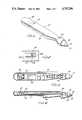
- FIG. 1is a perspective drawing of the tonometer.
- FIG. 2is a front view of the liquid crystal display.
- FIG. 3is a top view of the tonometer showing the placement of the various components inside the instrument.
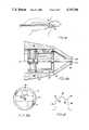
- FIG. 4is a section view of the tonometer showing component placement.
- FIG. 5is a system diagram.
- FIG. 6is a perspective drawing of the instrument as used to make a pressure reading on a patient's eye.
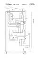
- FIG. 7is a circuit diagram of the three-stage amplifier with its associated baseline reference nulling circuit.
- FIG. 8is a waveform resulting from a pressure measurement.
- FIG. 9Ais a section view of the pressure transducer and FIG. 9B is a top view of strain gauges on a plate which is shown in position in FIG. 9A by arrows 9B.
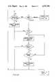
- FIG. 10A through 10Care flow diagrams of a program.
- the tonometerconsists of a housing that is contoured such that it is easily grasped, in a manner of a writing pen.
- the tip of the instrumentis the solid state pressured transducer element.
- the other functioning components of the instrumentinclude an activation button, located on the anterior dorsel surface in close approximation to the index fingertip of the user, a liquid crystal display, a reset button, and a removable battery cover.
- the measurement transduceris a solid phase pressure sensitive element which produces a change in voltage with a change in intraocular pressure.
- the electrical waveform produced by gently bringing the transducer in contact with the corneais converted to a digital signal and processed by a microprocessor.
- the microprocessoris highly interactive with the amplifier circuitry, insuring accurate data acquisition and control.
- the microprocessoruses multiple criteria such as slope and configuration of the waveform for accepting a reading as valid and then calculates the average intraocular pressure along with an estimate of its reliability. An average pressure value and the reliability are then read out on a liquid crystal display.
- FIG. 1shows a perspective view of the tonometer 20.
- the tonometer 20has a housing 22 which is formed so that a user can grasp the instrument and have his or her index finger over activation switch 24.
- the transducer housing 26,contains a strain gauge that is used to convert the pressure indications from the cornea to electrical impulses.
- the contact head 28 of the transducer housing 26has a thin rubber membrane which covers a central post 34 (FIG. 4) attached to the strain gauge 36. After repeated measures are obtained by intermittent contact with the cornea, the pressure is then read out on the liquid crystal display 30 shown in FIG. 2.
- FIG. 3is a top view of the tonometer 20 with its various components.
- the batteries 40are located toward the rear of the tonometer. Adjacent to the batteries 40 is the display 30 and adjacent to the display 30 is a microprocessor 42.
- a three-stage high-gain amplifier 46 and its baseline reference nulling circuitare located forward of the microprocessor on a printed circuit board 44 (FIG. 4).
- the activation button 24is located on the top forward portion of the instrument for easy operation by the user.
- the transducercomprises a contact head 28 and an internal assembly 29.
- the contact head 28contains two components, a base 48 and a central post 34.
- the central post 34is flush with the base 48, but may vary up to 0.5 microns from the base 48 without affecting the measurement.
- the central post 34is welded to two flexures 33 and 35 which are 0.002 of an inch thick and one half inch in diameter. Multiple cutouts 37 are shown which serve to decrease mass while preserving strength of the elements.
- the anterior flexure 33is passive, serving primarily to align the posts.
- the posterior flexure 35is active in the measurement in intraocular pressure.
- the circuitryis configured as a Wheatstone bridge. Balancing resistors and thermal correction resistors are added to the circuit, as required.
- a voltage of two to six voltsis utilized to activate the bridge when pressure is applied to the central post 34. This force causes a change in the flexure state which is proportional to an output voltage.
- a stop 41is placed posterior to the active flexure in order to protect against accidental long excursions of the post.
- the central posthas a mass which produces a measurable force when the transducer is moved from a "tip down" to a "tip up” position.
- the calibration modeis initiated by two presses of the activation button 24 in rapid succession. There is an automatic calibration of the electrical output of the transducer to an interval value representing the force supplied by gravity on the mass of the central post 34. If the discrepancy between stored and calibrated values differ by 10%, the instrument cannot be put into the measurement mode. Recalibration, however, can be attempted.
- the transducermust be aligned perpendicularly to the corneal surface as shown in FIG. 6 wherein the tonometer 20 is shown aligned with the visual axis 23 of the eye 21. Incomplete or off-axis contact results in slow and/or inadequate excursion of the post.
- a sharply rising edge of the electrical waveformis elicited from the transducer shown as edge 90 in FIG. 8.
- Continuing pressure beyond that necessary to contact the cornearesults in an artificial elevation of intraocular pressure by the instrument itself, shown in FIG. 8 as peak 93.
- peak 93At the point of optimal contact, there is a minimal indentation of the cornea by the base of the transducer tip. This results in a small transient depression 92 of voltage which best correlates with intraocular pressure as determined by manometric techniques.
- the output voltage of the transducer 36is ac coupled. To prevent a wandering baseline between measurements, a capacitor is shorted just prior to activating the transducer.
- the analog electrical signalis then digitized by the microprocessor 42 at a sampling rate of 200 to 300 Hz. Up to 32 sequential values are stored in random access memory in the microprocessor 42 and analyzed.
- Analysisbegins upon momentary application of the contact head 28 to the eye and consists of determining criteria for the baseline, for perpendicular application and release of the transducer to/from the cornea, and for optimal indentation.
- a brief clickis heard by the user, supplied by the microspeaker 50, and which is elicited by a train of electrical signals delivered from the microprocessor 42 to the microspeaker 50 mounted on the printed circuit board. All readable measures of intraocular pressure are averaged after six measurements are obtained. The range is then computed.
- a "beep”is given by means of a medium frequency output from the microprocessor 42 to the microspeaker 50, signaling that a reading has been obtained.
- the mean intraocular pressure in millimeters of mercury (Hg)is then shown on the liquid crystal display 30.
- One or more of four annunciator bars 34A, 34B, 34C and 34Dmay be illuminated denoting a correlation variance which is plus or minus 5% of the mean, shown by annunciator 34A, plus or minus 10% of the mean, shown by annunciator 34B, plus or minus 20% of the mean, shown by annunciator 34C, and greater than plus or minus 20% of the mean, shown by annunciator 34D. If ten applications of the transducer are made without achieving six readable measurements, no numeric value is displayed and the "beep" is given. The annunciator bars are shown in FIG. 2 in relationship to the display 30.
- FIG. 6shows the tonometer 20 being used to make a pressure measurement on a patient's eye 21 along the visual axis as shown by dotted line 23.
- FIG. 5shows a detailed system block diagram which consists of a three-stage high-gain amplifier 46 with its associated baseline reference nulling circuit, a microprocessor 42 and a display 30.
- Components C1, C2, C4, C8 and C10are capacitors; components R1, R2, RN1-1, RN1-2, RN2-1, RN2-3, RN2-4, R9, R10, R15 and R16 are resistors; components Q2, Q3, Q4 and Q5 are transistors; component U4D is an operational amplifier; components U2A, U2B and U2C are NAND gates and component 50 is a microspeaker.
- the strain gauge 36(FIG. 4) is used to convert the intraocular pressure of the eye to an electrical impulse.
- the central post 34 of the strain gauge 36is caused to move which in turn causes the plate 35 on which the strain gauges are mounted to bend slightly. That in turn causes the resistance of the strain gauges 39 to increase/decrease.
- the strain gaugeforms two of the resistive elements of a Wheatstone bridge.
- the output of the Wheatstone bridgeis connected to the three-stage high-gain amplifier 46 where the signal is amplified for input to the microprocessor 42.
- the microprocessorthen follows the sequence shown in the flow chart of FIGS. 10A through 10C to perform the analysis on the waveform from the three-stage high-gain amplifier 46. In that analysis, shown in the flow chart of FIGS. 10A through 10C, the dc component offset or baseline must be subtracted from the pressure waveform, shown in FIG. 8, to determine the relative differential signal of interest.
- a baseline searchis initiated and then the baseline is tracked. If the change is positive, then the system tracks the rising edge. The slope of the rising edge is tracked until there is either no change or the change is negative. If there are consecutive samples in which there is no change, then a pressure reading is computed and the system then looks for a falling edge. If the slope is negative and the slope is greater than or equal to 5, then the system searches for the pressure and computes it. After the pressure reading is computed, the system analyzes for a falling edge as shown in FIG. 10B. The system then searches for a baseline. If no baseline is found, then the system exits the routine. If a baseline is found, then the baseline is tracked for a falling edge.
- the routineis exited. If there is no change, then the average of the last eight samples is computed and the system returns to the block in which the baseline is tracked for a falling edge. If the sample change is positive, then the system tracks the rising edge until there is no change or the change is negative. If there are three consecutive "no change" readings, then the pressure reading is computed and the routine is exited. If the sample change is negative and the slope is less than or equal to 5, then the routine is exited. If the slope is greater than or equal to 5, then there is a pressure search for a falling edge. If there are greater than ten samples in this search, then the routine is exited. If there are less than ten samples, then the pressure search for the falling edge is repeated until the pressure is found at which time the pressure is computed. After the pressure reading is computed, the routine is exited.
- state 1 of the microprocessor logicinvolves finding a stable amplifier baseline to reference and calculate the relative amplitude of the pressure waveform shown in FIG. 8. To accomplish this, the micropressure applies an active high (capacitor discharge) signal from lead 78 to control lines 54 and 56 of the analog switches 58 and 60 for a period of 60 mS. This nulls both the second stage 62 and the third stage 64 of the amplifier circuitry by equalizing the charge on both sides of capacitors 66 and 68.
- active highcapacitor discharge
- the charge of the capacitorsare neutralized because there is a 1.5 volt reference voltage supplied on lead 71 which equals the reference voltage of the second stage amplifier and is applied on the second-stage amplifier side of capacitor 66. Similarly, a 0.4 volt, set by resistors 72 and 74, is directly applied to the third-stage side of the capacitor 68 which equals this stage's reference voltage. This neutralizing effect equalizes both differential inputs for each amplifier stage resulting in a gain of zero, and removing any carrier signal.
- the capacitor discharge signal on leads 54 and 56is terminated, which opens both of the analog switches 58 and 60 controlled by the microprocessor 42. During the 60 millisecond time period the microprocessor is processing data already received.
- Microprocessor 42shown in FIG. 7, is also shown as microprocessor 42 in FIG. 5.
- This designis unique because the microprocessor is able to use the capacitor discharge control to reach the baseline when needed, while dynamically processing the pressure waveform data.
- the amplifiers 62 and 64are effectively dc coupled (since there is virtually an infinite time constant) which gives the microprocessor 42 a dc level signal to process. In a conventional ac coupled amplifier circuit, nulling would have to be accomplished either by complex precision auto-nulling hardware circuit or by operator manual calibration before instrument use.
- the microprocessor 42 and transducer elementsare turned off in order to conserve power and preserve the battery life.
- a small discrete circuitperforms this function and also responds to depression of the activation button by activating the electronic elements and the transducer.
- All elements of the tonometer instrumentare connected to a multilayered circuit board. Mounted off the circuit board are four silver oxide batteries. Mounted on the circuit board 44 are the microprocessor, the microspeaker, and the discrete circuitry related to "wake-up" and transducer signal processing. Also on the circuit board are connectors to the display 30, the activation button 24, and the RS232 computer interface connector 32.
Landscapes
- Life Sciences & Earth Sciences (AREA)
- Health & Medical Sciences (AREA)
- Surgery (AREA)
- Biophysics (AREA)
- Ophthalmology & Optometry (AREA)
- Engineering & Computer Science (AREA)
- Biomedical Technology (AREA)
- Heart & Thoracic Surgery (AREA)
- Medical Informatics (AREA)
- Molecular Biology (AREA)
- Physics & Mathematics (AREA)
- Animal Behavior & Ethology (AREA)
- General Health & Medical Sciences (AREA)
- Public Health (AREA)
- Veterinary Medicine (AREA)
- Eye Examination Apparatus (AREA)
- Investigating Or Analyzing Materials By The Use Of Electric Means (AREA)
- Heterocyclic Carbon Compounds Containing A Hetero Ring Having Oxygen Or Sulfur (AREA)
- Measurement And Recording Of Electrical Phenomena And Electrical Characteristics Of The Living Body (AREA)
- Measurement Of The Respiration, Hearing Ability, Form, And Blood Characteristics Of Living Organisms (AREA)
Abstract
Description
Claims (4)
Priority Applications (5)
| Application Number | Priority Date | Filing Date | Title |
|---|---|---|---|
| US06/781,240US4747296A (en) | 1985-09-27 | 1985-09-27 | Electronic tonometer with baseline nulling system |
| EP86307393AEP0217642B1 (en) | 1985-09-27 | 1986-09-25 | Hand-held self-contained electronic tonometer |
| AT86307393TATE101506T1 (en) | 1985-09-27 | 1986-09-25 | PORTABLE INDEPENDENT ELECTRONIC IONOMETER. |
| DE3689643TDE3689643T2 (en) | 1985-09-27 | 1986-09-25 | Portable independent electronic ionometer. |
| JP61227909AJPH08107B2 (en) | 1985-09-27 | 1986-09-26 | Electronic tonometer |
Applications Claiming Priority (1)
| Application Number | Priority Date | Filing Date | Title |
|---|---|---|---|
| US06/781,240US4747296A (en) | 1985-09-27 | 1985-09-27 | Electronic tonometer with baseline nulling system |
Publications (1)
| Publication Number | Publication Date |
|---|---|
| US4747296Atrue US4747296A (en) | 1988-05-31 |
Family
ID=25122117
Family Applications (1)
| Application Number | Title | Priority Date | Filing Date |
|---|---|---|---|
| US06/781,240Expired - LifetimeUS4747296A (en) | 1985-09-27 | 1985-09-27 | Electronic tonometer with baseline nulling system |
Country Status (5)
| Country | Link |
|---|---|
| US (1) | US4747296A (en) |
| EP (1) | EP0217642B1 (en) |
| JP (1) | JPH08107B2 (en) |
| AT (1) | ATE101506T1 (en) |
| DE (1) | DE3689643T2 (en) |
Cited By (26)
| Publication number | Priority date | Publication date | Assignee | Title |
|---|---|---|---|---|
| US4926674A (en)* | 1988-11-03 | 1990-05-22 | Innovex Inc. | Self-zeroing pressure signal generator |
| US4987898A (en)* | 1989-01-17 | 1991-01-29 | Noninvasive Medical Incorporated | Method and device for the non-invasive measurement of pressure |
| US5042484A (en)* | 1987-10-13 | 1991-08-27 | Kabushiki Kaisha Topcon | Air puff type tonometer |
| US5116051A (en)* | 1989-01-12 | 1992-05-26 | Atari Games Corporation | Strain gauge pressure-sensitive video game control |
| US5142921A (en)* | 1990-10-29 | 1992-09-01 | Litton Systems, Inc. | Force balance instrument with electrostatic charge control |
| US5309777A (en)* | 1990-09-01 | 1994-05-10 | S & G Schmitt Messgeraetebau Gmbh | Measuring instrument particularly useful for measuring waste gases from heating installations |
| DE4444459C1 (en)* | 1994-12-14 | 1996-02-29 | Jenoptik Technologie Gmbh | Instrument for automatic measurement of compressive force for eye examinations |
| US5810005A (en) | 1993-08-04 | 1998-09-22 | Dublin, Jr.; Wilbur L. | Apparatus and method for monitoring intraocular and blood pressure by non-contact contour measurement |
| US6113542A (en)* | 1998-12-15 | 2000-09-05 | Hyman; George F. | Diagnostic apparatus and method to provide effective intraocular pressure based on measured thickness of the cornea |
| EP1121895A2 (en) | 2000-02-07 | 2001-08-08 | Leica Microsystems Inc. , Ophthalmic Instruments Division | Hand-held non-contact tonometer |
| WO2002091907A2 (en) | 2001-05-16 | 2002-11-21 | Marco Ophthalmic, Inc. | Applanation tonometer |
| US6524243B1 (en)* | 2000-10-04 | 2003-02-25 | Jordan Technology Inc. | Tonometer incorporating an electrical measurement device |
| US6565585B2 (en) | 2001-06-22 | 2003-05-20 | Nidek Co., Ltd. | Corneal surgical apparatus |
| RU2212033C2 (en)* | 2001-06-25 | 2003-09-10 | Всероссийский центр медицины катастроф "Защита" | Facility establishing compression properties of articles made of elastic materials |
| US6623429B2 (en) | 2001-11-06 | 2003-09-23 | Reichert, Inc. | Hand-held non-contact tonometer |
| US6673014B2 (en) | 2001-10-05 | 2004-01-06 | Itonix, Inc. | Noninvasive methods and apparatuses for measuring the intraocular pressure of a mammal eye |
| US20040193033A1 (en)* | 2002-10-04 | 2004-09-30 | Badehi Avner Pierre | Noninvasive methods and apparatuses for measuring the intraocular pressure of a mammal eye |
| WO2005065529A1 (en)* | 2004-01-12 | 2005-07-21 | Emil Hohl | Method and device for measuring the internal pressure of an elastic test body, in particular for measuring the intra-ocular pressure |
| US6923765B2 (en) | 2001-11-21 | 2005-08-02 | A. Mateen Ahmed | Tonometer and method of use |
| US20050182312A1 (en)* | 2004-02-12 | 2005-08-18 | Medtronic Xomed, Inc. | Contact tonometer using MEMS technology |
| US20050231686A1 (en)* | 2002-06-27 | 2005-10-20 | Sis Ag, Surgical Instrument Systems | Device for detecting measurands in an eye |
| US20060217611A1 (en)* | 2003-06-03 | 2006-09-28 | Autotonometer Corporation | Ophthalmologic Applanation Prism Replacement System for Eye Examining Instrument |
| US20070123768A1 (en)* | 2005-11-30 | 2007-05-31 | Duke University | Ophthalmic instruments, systems and methods especially adapted for conducting simultaneous tonometry and pachymetry measurements |
| US20090203985A1 (en)* | 2005-10-14 | 2009-08-13 | Ehrecke Timothy J | Pressure Monitor |
| US9005125B1 (en)* | 2010-02-04 | 2015-04-14 | A. Mateen Ahmed | Tonometer |
| US12295656B2 (en)* | 2016-02-25 | 2025-05-13 | Ocuflow, Inc. | Composite ocular blood flow analyzer |
Families Citing this family (2)
| Publication number | Priority date | Publication date | Assignee | Title |
|---|---|---|---|---|
| RU1755427C (en)* | 1986-02-25 | 1995-01-20 | Козин Михаил Петрович | Eye tonometer |
| JP4615772B2 (en)* | 2001-07-12 | 2011-01-19 | 株式会社ニデック | Cornea surgery device |
Citations (21)
| Publication number | Priority date | Publication date | Assignee | Title |
|---|---|---|---|---|
| US3266288A (en)* | 1964-04-30 | 1966-08-16 | Intercontinental Dynamics Corp | Automatic pressure generating and regulating system |
| US3366948A (en)* | 1963-07-19 | 1968-01-30 | Int Standard Electric Corp | Reference level zero adjuster for analog to digital converter |
| FR1549197A (en)* | 1967-03-13 | 1968-12-13 | ||
| US3475600A (en)* | 1966-02-28 | 1969-10-28 | Infotronics Corp | Base line control circuit means |
| US3641444A (en)* | 1970-09-01 | 1972-02-08 | Atomic Energy Commission | Baseline compensating integrator |
| US3748587A (en)* | 1969-05-21 | 1973-07-24 | Sercel Rech Const Elect | Continuous amplifier assembly with drift correction |
| US3781869A (en)* | 1972-03-20 | 1973-12-25 | Inservco Inc | Transducer amplifier with automatic balance |
| US3810031A (en)* | 1971-05-19 | 1974-05-07 | Commissariat Energie Atomique | Integrated amplifying device having low drift and method of compensating for the drift of an amplifying device |
| US3884079A (en)* | 1973-01-15 | 1975-05-20 | Gen Signal Corp | Force balance differential pressure transmitter |
| US3889518A (en)* | 1973-12-26 | 1975-06-17 | American Optical Corp | Device for consistent response to a fluid pulse and method and apparatus for verifying instruments utilizing fluid pulses |
| US3924612A (en)* | 1974-01-28 | 1975-12-09 | Philip T Dempster | Spirometer apparatus and method |
| US3926056A (en)* | 1974-09-26 | 1975-12-16 | Us Navy | Conductivity, temperature and pressure measuring system |
| US4003370A (en)* | 1975-10-14 | 1977-01-18 | American Hospital Supply Corporation | Blood pressure monitor system and method |
| JPS5236077A (en)* | 1975-09-17 | 1977-03-19 | Kosei Seisakusho:Kk | Zero point correction device for sensors of pressure measuring apparat us of injection molding machines |
| US4086804A (en)* | 1976-10-26 | 1978-05-02 | Sperry Rand Corporation | Precision pneumatic pressure supply system |
| US4088009A (en)* | 1973-06-09 | 1978-05-09 | Akira Fukuda | Air micrometer |
| JPS5544943A (en)* | 1978-09-26 | 1980-03-29 | Toshiba Corp | Pressure transducer |
| JPS55135724A (en)* | 1979-04-10 | 1980-10-22 | Hitachi Ltd | Pressure sensor |
| US4263918A (en)* | 1977-03-21 | 1981-04-28 | Biomega Corporation | Methods of and apparatus for the measurement of blood pressure |
| US4322977A (en)* | 1980-05-27 | 1982-04-06 | The Bendix Corporation | Pressure measuring system |
| US4532809A (en)* | 1981-10-05 | 1985-08-06 | Allied Corporation | Pressure measuring systems with increased accuracy for a constant resolution |
Family Cites Families (8)
| Publication number | Priority date | Publication date | Assignee | Title |
|---|---|---|---|---|
| US3564907A (en)* | 1967-11-17 | 1971-02-23 | Univ Johns Hopkins | Applanation tonometer |
| US3580243A (en)* | 1968-10-21 | 1971-05-25 | Marquette Electronics Inc | Means and method for subtracting dc noise from electrocardiographic signals |
| US3724263A (en) | 1970-09-29 | 1973-04-03 | Bio Optronics Inc | Electrical digital display tonometer |
| US4192317A (en)* | 1978-06-30 | 1980-03-11 | Ical, Incorporated | Indentation tonometer |
| US4213348A (en)* | 1979-08-01 | 1980-07-22 | Medasonics, Inc. | Self-calibrating automatic zeroing strain gauge circuit |
| JPS57113515U (en)* | 1980-12-29 | 1982-07-14 | ||
| FR2550083B1 (en)* | 1983-08-03 | 1985-11-29 | Berger Henri | APPARATUS AND METHOD FOR MEASURING BLOOD PRESSURE USING AN INDIRECT METHOD |
| US4817432A (en) | 1985-09-27 | 1989-04-04 | Design Team Partners | Digital ultrasonic instrument for ophthalmic use |
- 1985
- 1985-09-27USUS06/781,240patent/US4747296A/ennot_activeExpired - Lifetime
- 1986
- 1986-09-25DEDE3689643Tpatent/DE3689643T2/ennot_activeExpired - Fee Related
- 1986-09-25EPEP86307393Apatent/EP0217642B1/ennot_activeExpired - Lifetime
- 1986-09-25ATAT86307393Tpatent/ATE101506T1/ennot_activeIP Right Cessation
- 1986-09-26JPJP61227909Apatent/JPH08107B2/ennot_activeExpired - Lifetime
Patent Citations (21)
| Publication number | Priority date | Publication date | Assignee | Title |
|---|---|---|---|---|
| US3366948A (en)* | 1963-07-19 | 1968-01-30 | Int Standard Electric Corp | Reference level zero adjuster for analog to digital converter |
| US3266288A (en)* | 1964-04-30 | 1966-08-16 | Intercontinental Dynamics Corp | Automatic pressure generating and regulating system |
| US3475600A (en)* | 1966-02-28 | 1969-10-28 | Infotronics Corp | Base line control circuit means |
| FR1549197A (en)* | 1967-03-13 | 1968-12-13 | ||
| US3748587A (en)* | 1969-05-21 | 1973-07-24 | Sercel Rech Const Elect | Continuous amplifier assembly with drift correction |
| US3641444A (en)* | 1970-09-01 | 1972-02-08 | Atomic Energy Commission | Baseline compensating integrator |
| US3810031A (en)* | 1971-05-19 | 1974-05-07 | Commissariat Energie Atomique | Integrated amplifying device having low drift and method of compensating for the drift of an amplifying device |
| US3781869A (en)* | 1972-03-20 | 1973-12-25 | Inservco Inc | Transducer amplifier with automatic balance |
| US3884079A (en)* | 1973-01-15 | 1975-05-20 | Gen Signal Corp | Force balance differential pressure transmitter |
| US4088009A (en)* | 1973-06-09 | 1978-05-09 | Akira Fukuda | Air micrometer |
| US3889518A (en)* | 1973-12-26 | 1975-06-17 | American Optical Corp | Device for consistent response to a fluid pulse and method and apparatus for verifying instruments utilizing fluid pulses |
| US3924612A (en)* | 1974-01-28 | 1975-12-09 | Philip T Dempster | Spirometer apparatus and method |
| US3926056A (en)* | 1974-09-26 | 1975-12-16 | Us Navy | Conductivity, temperature and pressure measuring system |
| JPS5236077A (en)* | 1975-09-17 | 1977-03-19 | Kosei Seisakusho:Kk | Zero point correction device for sensors of pressure measuring apparat us of injection molding machines |
| US4003370A (en)* | 1975-10-14 | 1977-01-18 | American Hospital Supply Corporation | Blood pressure monitor system and method |
| US4086804A (en)* | 1976-10-26 | 1978-05-02 | Sperry Rand Corporation | Precision pneumatic pressure supply system |
| US4263918A (en)* | 1977-03-21 | 1981-04-28 | Biomega Corporation | Methods of and apparatus for the measurement of blood pressure |
| JPS5544943A (en)* | 1978-09-26 | 1980-03-29 | Toshiba Corp | Pressure transducer |
| JPS55135724A (en)* | 1979-04-10 | 1980-10-22 | Hitachi Ltd | Pressure sensor |
| US4322977A (en)* | 1980-05-27 | 1982-04-06 | The Bendix Corporation | Pressure measuring system |
| US4532809A (en)* | 1981-10-05 | 1985-08-06 | Allied Corporation | Pressure measuring systems with increased accuracy for a constant resolution |
Non-Patent Citations (2)
| Title |
|---|
| "Carrier Amplifier Has Zero Drift"; Electronics, vol. 25, No. 12, pp. 131-133; Dec. 1952; Angelo Perone. |
| Carrier Amplifier Has Zero Drift ; Electronics, vol. 25, No. 12, pp. 131 133; Dec. 1952; Angelo Perone.* |
Cited By (33)
| Publication number | Priority date | Publication date | Assignee | Title |
|---|---|---|---|---|
| US5042484A (en)* | 1987-10-13 | 1991-08-27 | Kabushiki Kaisha Topcon | Air puff type tonometer |
| US4926674A (en)* | 1988-11-03 | 1990-05-22 | Innovex Inc. | Self-zeroing pressure signal generator |
| US5116051A (en)* | 1989-01-12 | 1992-05-26 | Atari Games Corporation | Strain gauge pressure-sensitive video game control |
| US4987898A (en)* | 1989-01-17 | 1991-01-29 | Noninvasive Medical Incorporated | Method and device for the non-invasive measurement of pressure |
| US5309777A (en)* | 1990-09-01 | 1994-05-10 | S & G Schmitt Messgeraetebau Gmbh | Measuring instrument particularly useful for measuring waste gases from heating installations |
| US5142921A (en)* | 1990-10-29 | 1992-09-01 | Litton Systems, Inc. | Force balance instrument with electrostatic charge control |
| US5810005A (en) | 1993-08-04 | 1998-09-22 | Dublin, Jr.; Wilbur L. | Apparatus and method for monitoring intraocular and blood pressure by non-contact contour measurement |
| US6110110A (en) | 1993-08-04 | 2000-08-29 | Dublin, Jr.; Wilbur Leslie | Apparatus and method for monitoring intraocular and blood pressure by non-contact contour measurement |
| DE4444459C1 (en)* | 1994-12-14 | 1996-02-29 | Jenoptik Technologie Gmbh | Instrument for automatic measurement of compressive force for eye examinations |
| US6113542A (en)* | 1998-12-15 | 2000-09-05 | Hyman; George F. | Diagnostic apparatus and method to provide effective intraocular pressure based on measured thickness of the cornea |
| EP1121895A2 (en) | 2000-02-07 | 2001-08-08 | Leica Microsystems Inc. , Ophthalmic Instruments Division | Hand-held non-contact tonometer |
| US6361495B1 (en) | 2000-02-07 | 2002-03-26 | Leica Microsystems Inc. | Hand-held non-contact tonometer |
| EP1419729A1 (en) | 2000-02-07 | 2004-05-19 | Leica Microsystems Inc. , Ophthalmic Instruments Division | Alignment guidance system |
| JP2007196069A (en)* | 2000-02-07 | 2007-08-09 | Reichert Inc | Hand-held non-contact tonometer |
| US6524243B1 (en)* | 2000-10-04 | 2003-02-25 | Jordan Technology Inc. | Tonometer incorporating an electrical measurement device |
| WO2002091907A2 (en) | 2001-05-16 | 2002-11-21 | Marco Ophthalmic, Inc. | Applanation tonometer |
| US20040236204A1 (en)* | 2001-05-16 | 2004-11-25 | Marco Opthamalmic, Inc. | Tip cover for appellation tonometer |
| US6776756B2 (en) | 2001-05-16 | 2004-08-17 | Marco Ophthalmic, Inc. | Applanation tonometer |
| US6565585B2 (en) | 2001-06-22 | 2003-05-20 | Nidek Co., Ltd. | Corneal surgical apparatus |
| RU2212033C2 (en)* | 2001-06-25 | 2003-09-10 | Всероссийский центр медицины катастроф "Защита" | Facility establishing compression properties of articles made of elastic materials |
| US6673014B2 (en) | 2001-10-05 | 2004-01-06 | Itonix, Inc. | Noninvasive methods and apparatuses for measuring the intraocular pressure of a mammal eye |
| US6623429B2 (en) | 2001-11-06 | 2003-09-23 | Reichert, Inc. | Hand-held non-contact tonometer |
| DE10297414B4 (en)* | 2001-11-06 | 2008-09-25 | Reichert, Inc. | Hand-held tonometer and combination with an associated holder |
| US6923765B2 (en) | 2001-11-21 | 2005-08-02 | A. Mateen Ahmed | Tonometer and method of use |
| US20050231686A1 (en)* | 2002-06-27 | 2005-10-20 | Sis Ag, Surgical Instrument Systems | Device for detecting measurands in an eye |
| US20040193033A1 (en)* | 2002-10-04 | 2004-09-30 | Badehi Avner Pierre | Noninvasive methods and apparatuses for measuring the intraocular pressure of a mammal eye |
| US20060217611A1 (en)* | 2003-06-03 | 2006-09-28 | Autotonometer Corporation | Ophthalmologic Applanation Prism Replacement System for Eye Examining Instrument |
| WO2005065529A1 (en)* | 2004-01-12 | 2005-07-21 | Emil Hohl | Method and device for measuring the internal pressure of an elastic test body, in particular for measuring the intra-ocular pressure |
| US20050182312A1 (en)* | 2004-02-12 | 2005-08-18 | Medtronic Xomed, Inc. | Contact tonometer using MEMS technology |
| US20090203985A1 (en)* | 2005-10-14 | 2009-08-13 | Ehrecke Timothy J | Pressure Monitor |
| US20070123768A1 (en)* | 2005-11-30 | 2007-05-31 | Duke University | Ophthalmic instruments, systems and methods especially adapted for conducting simultaneous tonometry and pachymetry measurements |
| US9005125B1 (en)* | 2010-02-04 | 2015-04-14 | A. Mateen Ahmed | Tonometer |
| US12295656B2 (en)* | 2016-02-25 | 2025-05-13 | Ocuflow, Inc. | Composite ocular blood flow analyzer |
Also Published As
| Publication number | Publication date |
|---|---|
| DE3689643D1 (en) | 1994-03-24 |
| EP0217642B1 (en) | 1994-02-16 |
| EP0217642A2 (en) | 1987-04-08 |
| JPH08107B2 (en) | 1996-01-10 |
| JPS62122632A (en) | 1987-06-03 |
| EP0217642A3 (en) | 1988-06-01 |
| ATE101506T1 (en) | 1994-03-15 |
| DE3689643T2 (en) | 1994-05-19 |
Similar Documents
| Publication | Publication Date | Title |
|---|---|---|
| US4747296A (en) | Electronic tonometer with baseline nulling system | |
| US3992926A (en) | Pressure measuring method and apparatus with digital readout | |
| EP0219988B1 (en) | Self-contained hand-held ultrasonic instrument for ophthalmic use | |
| US5165409A (en) | Tonometry apparatus | |
| US5375610A (en) | Apparatus for the functional assessment of human activity | |
| US4688582A (en) | Portable hand-held tympanometer | |
| US6792801B2 (en) | Device for measuring force and angles | |
| EP0474650A1 (en) | Dolorimeter apparatus. | |
| US20210345877A1 (en) | Method and device for self-measurement of intra-ocular pressure | |
| GB2228330A (en) | Non-invasive measurement of pressure | |
| EP0823238A1 (en) | Pulse wave detecting device | |
| JP2003532473A (en) | Intraocular pressure test | |
| US6394968B1 (en) | Trans-scleral method and apparatus for measuring intraocular pressure | |
| KR0167776B1 (en) | Pressure detector | |
| US20070121067A1 (en) | Intraocular pressure and biomechanical properties measurement device and method | |
| US3452589A (en) | Apparatus for measuring stress-strain characteristics | |
| US20060084856A1 (en) | Combination ophthalmic instrument | |
| US4886066A (en) | Tonometer having acoustic coupling detection | |
| JP3121300B2 (en) | Skin condition measuring device | |
| CA1291796C (en) | Hand-held self-contained electronic tonometer | |
| US20060241437A1 (en) | Pachymeter | |
| US20060129068A1 (en) | Palpometer and methods of use thereof | |
| GB2153535A (en) | Sphygmomanometer | |
| CN220025020U (en) | Film sensor for measuring eyelid force and eyelid pressure measuring equipment | |
| CN220800997U (en) | Portable intelligent blood pressure detection watch |
Legal Events
| Date | Code | Title | Description |
|---|---|---|---|
| AS | Assignment | Owner name:DESIGN TEAM PARTNERS, 442 WEST COLORADO, GLENDALE, Free format text:ASSIGNMENT OF ASSIGNORS INTEREST.;ASSIGNORS:FELDON, STEVEN E.;WALLACE, DAVID A.;MEZACK, GARY;AND OTHERS;REEL/FRAME:004472/0958 Effective date:19850927 | |
| AS | Assignment | Owner name:BIO-RAD LABORATORIES, INC., ("BIO-RAD"), MASSACHUS Free format text:ASSIGNMENT OF ASSIGNORS INTEREST.;ASSIGNOR:OCULAB, INC.;REEL/FRAME:005023/0081 Effective date:19881202 | |
| FPAY | Fee payment | Year of fee payment:4 | |
| FEPP | Fee payment procedure | Free format text:PAT HLDR NO LONGER CLAIMS SMALL ENT STAT AS SMALL BUSINESS (ORIGINAL EVENT CODE: LSM2); ENTITY STATUS OF PATENT OWNER: SMALL ENTITY Free format text:PAYOR NUMBER ASSIGNED (ORIGINAL EVENT CODE: ASPN); ENTITY STATUS OF PATENT OWNER: SMALL ENTITY | |
| AS | Assignment | Owner name:OCCULAB INC. A CORP. OF CALIFORNIA, CALIFORNIA Free format text:NUNC PRO TUNC ASSIGNMENT EFFECTIVE AS OF DECEMBER 2, 1988;ASSIGNOR:DESIGN TEAM PARTNERS;REEL/FRAME:006209/0053 Effective date:19920725 | |
| AS | Assignment | Owner name:MENTOR O&O, INC., MASSACHUSETTS Free format text:ASSIGNMENT OF ASSIGNORS INTEREST;ASSIGNOR:BIO-RAD LABORATORIES, INC.;REEL/FRAME:006912/0879 Effective date:19940315 | |
| FEPP | Fee payment procedure | Free format text:PAT HOLDER CLAIMS SMALL ENTITY STATUS - SMALL BUSINESS (ORIGINAL EVENT CODE: SM02); ENTITY STATUS OF PATENT OWNER: SMALL ENTITY | |
| FPAY | Fee payment | Year of fee payment:8 | |
| AS | Assignment | Owner name:MENTOR OPHTHALMICS, INC., CALIFORNIA Free format text:CHANGE OF NAME;ASSIGNOR:MENTOR O&O, INC.;REEL/FRAME:007978/0896 Effective date:19950901 | |
| AS | Assignment | Owner name:XOMED, INC., FLORIDA Free format text:ASSIGNMENT OF ASSIGNORS INTEREST;ASSIGNOR:MENTOR OPHTHALMICS, INC.;REEL/FRAME:010340/0431 Effective date:19991004 | |
| REMI | Maintenance fee reminder mailed | ||
| FP | Lapsed due to failure to pay maintenance fee | Effective date:20000531 | |
| FEPP | Fee payment procedure | Free format text:PETITION RELATED TO MAINTENANCE FEES FILED (ORIGINAL EVENT CODE: PMFP); ENTITY STATUS OF PATENT OWNER: SMALL ENTITY Free format text:PETITION RELATED TO MAINTENANCE FEES GRANTED (ORIGINAL EVENT CODE: PMFG); ENTITY STATUS OF PATENT OWNER: SMALL ENTITY | |
| SULP | Surcharge for late payment | ||
| STCF | Information on status: patent grant | Free format text:PATENTED CASE | |
| PRDP | Patent reinstated due to the acceptance of a late maintenance fee | Effective date:20010413 |