US4745981A - Hydraulic impact tool - Google Patents
Hydraulic impact toolDownload PDFInfo
- Publication number
- US4745981A US4745981AUS06/760,389US76038985AUS4745981AUS 4745981 AUS4745981 AUS 4745981AUS 76038985 AUS76038985 AUS 76038985AUS 4745981 AUS4745981 AUS 4745981A
- Authority
- US
- United States
- Prior art keywords
- ram
- valve slide
- bore
- annular chamber
- fluid
- Prior art date
- Legal status (The legal status is an assumption and is not a legal conclusion. Google has not performed a legal analysis and makes no representation as to the accuracy of the status listed.)
- Expired - Fee Related
Links
- 239000012530fluidSubstances0.000claimsabstractdescription106
- 238000004146energy storageMethods0.000claimsabstractdescription22
- 238000007789sealingMethods0.000claimsdescription35
- 239000007789gasSubstances0.000description6
- IJGRMHOSHXDMSA-UHFFFAOYSA-NAtomic nitrogenChemical compoundN#NIJGRMHOSHXDMSA-UHFFFAOYSA-N0.000description4
- 238000003780insertionMethods0.000description3
- 230000037431insertionEffects0.000description3
- 230000036316preloadEffects0.000description3
- 229910052757nitrogenInorganic materials0.000description2
- 238000013459approachMethods0.000description1
- 239000010426asphaltSubstances0.000description1
- 238000005266castingMethods0.000description1
- 238000001816coolingMethods0.000description1
- 238000005520cutting processMethods0.000description1
- 230000007423decreaseEffects0.000description1
- 230000003247decreasing effectEffects0.000description1
- 239000000945fillerSubstances0.000description1
- 238000010304firingMethods0.000description1
- 238000004519manufacturing processMethods0.000description1
- 238000012986modificationMethods0.000description1
- 230000004048modificationEffects0.000description1
- 239000002689soilSubstances0.000description1
Images


Classifications
- B—PERFORMING OPERATIONS; TRANSPORTING
- B25—HAND TOOLS; PORTABLE POWER-DRIVEN TOOLS; MANIPULATORS
- B25D—PERCUSSIVE TOOLS
- B25D9/00—Portable percussive tools with fluid-pressure drive, i.e. driven directly by fluids, e.g. having several percussive tool bits operated simultaneously
- B25D9/06—Means for driving the impulse member
- B25D9/12—Means for driving the impulse member comprising a built-in liquid motor, i.e. the tool being driven by hydraulic pressure
- B—PERFORMING OPERATIONS; TRANSPORTING
- B25—HAND TOOLS; PORTABLE POWER-DRIVEN TOOLS; MANIPULATORS
- B25D—PERCUSSIVE TOOLS
- B25D9/00—Portable percussive tools with fluid-pressure drive, i.e. driven directly by fluids, e.g. having several percussive tool bits operated simultaneously
- B25D9/14—Control devices for the reciprocating piston
- B25D9/145—Control devices for the reciprocating piston for hydraulically actuated hammers having an accumulator
Definitions
- This inventionrelates in general to hydraulic tools, and in particular to tools for converting energy into a series of rapid, high energy impact blows.
- Hydraulic impact toolsgenerally have an energy storage device, such as a coil spring or gas spring, a ram, and a working tool.
- the energy storage devicecauses the ram to accelerate to deliver a blow to the working tool.
- Impact toolsare normally used for demolition purposes, such as breaking concrete, pavement, or ice, or for cutting asphalt. These tools can also be used for other jobs, such as compacting soil or driving pipe, posts, or pilings.
- U.S. patent application Ser. No. 640,728, filed Aug. 14, 1984,shows a hydraulic impact tool having a housing, a working tool, a ram, an energy storage device, and a valve slide.
- the toolalso has a high pressure fluid inlet port, an intermediate pressure fluid inlet port, and a single return line fluid outlet port.
- the return line fluid outletis for exhausting fluid from both the upper and intermediate annular chambers in the tool.
- the toolalso has a flow restriction means for restricting the flow of hydraulic fluid between the ram and the valve slide while the ram is moving toward the working tool.
- the first portexhausts the higher flow return volume from the upper annular chamber.
- the second portis for exhausting the higher pressure delatch volume from the intermediate annular chamber.
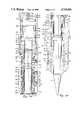
- FIGS. 1A and 1Bare a sectional view of an impact tool at the moment of impact.
- FIGS. 2A and 2Bare a sectional view of an impact tool at the end of the dwell time.
- FIGS. 3A and 3Bare a sectional view of an impact tool immediately prior to firing.
- FIG. 4is a sectional view of an impact tool along the lines 4--4 in FIG. 1.
- a typical working tool 11is shown mounted in the housng 13 of the hydraulic impact tool.
- Typical working toolsmay be moils, tampers, spades, or post drivers.
- the housing 13has an outer casing 15, which has a generally cylindrical bore 17.
- the working tool 11is mounted in the housing 13 by first inserting a preload bushing 19 into the bore 17 of the casing 15.
- a tool guide 20is placed around the shaft 21 of the working tool 11, and the working tool 11 is inserted into the bore 17 of the casing 15, until a knob 22 on the top of the working tool 11 contacts the preload bushing 19 and the preload bushing 19 contacts a shoulder 23 in the casing 15.
- the entire assemblyis then secured by four tool retainer pins 24 and a pin retainer ring 25.
- the retaining meansis best illustrated in FIG. 4.
- the pin retaining holes 26 in the casing 15 and grooves in the tool guide 20are aligned.
- the pin retainer ring 25is rotated until the pin insertion holes 27 are aligned with the pin retaining holes 26 on one side of the tool.
- Two of the retaining pins 24are then inserted.
- the pin retainer ring 25is then rotated until the pin insertion holes 27 are aligned with the pin retaining holes 26 on the other side of the tool.
- the remaining two retaining pins 24are inserted into the retaining holes 26.
- the retainer ring 25When all four retaining pins 24 have been installed, the retainer ring 25 is rotated to the position shown in FIG. 4. When the retainer ring 25 reaches this position, a spring-loaded plunger 28, mounted within the casing 15, locks within a hole 29 in the retainer ring 25 to secure the retainer ring 25 against rotation. If desired, a locking bolt 30 can then be inserted through the pin insertion hole 27, and threaded into the casing 15, to additionally secure the retainer ring 25 to the casing 15.
- the casing 15also has a pair of attachment flanges 31. These attachment flanges 31 are connected to adapter plates (not shown), which are used to attach the impact tool to a tractor-backhoe, excavator, or other similar vehicle.
- the casing 15 and the flanges 31may be integral if made from a casting or the like.
- the housing 13also has three generally cylindrical sleeves: a lower sleeve 33, a middle sleeve 35, and an upper sleeve 37.
- the lower sleeve 33shown in FIGS. 1B, 2B, and 3B, abuts a shoulder 39 in the casing 15.
- An O-ring seal 41seals between the lower sleeve 33 and the casing 15.
- a wear ring 43 and a seal assembly 45are located in grooves on the inner circumference of the lower sleeve 33.
- the seal assembly 45consists of a seal, a backup ring, a retaining ring, and a rod wiper.
- a plurality of ports 47allow fluid passage through the lower sleeve 33.
- a hydraulic line(not shown) is attached to the impact tool at a hydraulic fluid inlet 49. Hydraulic fluid, at an intermediate pressure, is thus supplied to the bore 17 of the casing 15 through the ports 47 in the lower sleeve 33.
- the middle sleeve 35has three O-ring seals 51, 53, 54, which seal between the middle sleeve 35 and the casing 15.
- One or more ports 55allow fluid flow through the middle sleeve 35, between the lower two of these O-ring seals 51, 53.
- the middle sleeve 35also has a bleed orifice hole 56, above the ports 55.
- a second hydraulic fluid inlet 57allows fluid pressure at a high pressure to be supplied to the bore 17 of the casing 15, through the port or ports 55.
- Another port, or a plurality of ports 58,allows fluid to flow through the middle sleeve 35, between the upper two O-ring seals 53, 54.
- a return line(not shown) is attached to the impact tool at a hydraulic fluid outlet 59 to exhaust fluid from within the middle sleeve 35, between the upper two O-ring seals 53, 54.
- a plurality of ports 61allow fluid to flow through the middle sleeve 35, and out a return line (not shown), which is attached to the impact tool at a hydraulic fluid outlet 63. Hydraulic fluid is thus exhausted from the bore 17 of the casing 15, through the ports 61 and the fluid outlet 63.
- the upper sleeve 37is threaded into the upper end of the casing 15.
- the upper sleeve 37abuts the middle sleeve 35 and locks the middle sleeve 35 and the lower sleeve 33 in place.
- An O-ring seal 65seals between the upper sleeve 37 and the casing 15.
- the upper sleeve 37has a plurality of vertical slots 67, and a plurality of horizontal slots 69, which provide for fluid flow between the vertical slots 67 and the hydraulic fluid outlet 63.
- An energy storage device 71is mounted in the upper end of the hydraulic impact tool.
- This devicemay be a coil spring or a gas spring, but in the preferred embodiment the energy storage device is a hydraulic actuator 71.
- the actuator 71has an outer cylinder 73, which is threaded onto the upper sleeve 37, until the outer cylinder 73 abuts the casing 15.
- An O-ring seal 75seals between the cylinder 73 and the upper sleeve 37.
- a cap 77is threaded into the top of the cylinder 73, and an O-ring seal 79 seals between the cap 77 and the inner circumference of the cylinder 73.
- a gassuch as nitrogen
- a cup-shaped piston 85is reciprocally located within the cylinder 73.
- the piston 85has a pair of wear rings 87, 88, a pair of piston rings 89, 90, and a pair of seals 91, 93 between the piston 85 and the inner circumference of the cylinder 73.
- the piston 85thus separates the gas in the upper end of the cylinder 73 from the hydraulic fluid in the lower end of the cylinder 73.
- a valve slide 95is located in the bore 17 within the middle sleeve 35.
- the valve slide 95is reciprocal between a lower position, shown in FIG. 2A, and an upper position, which is slightly higher than the position shown in FIGS. 1A and 3A.
- the outside diameter of the valve slide 95is smaller than the inside diameter of the middle sleeve 35.
- the outer circumference of the valve slide 95is sealed against the inner circumference of the middle sleeve 35.
- the valve slide 95has a piston ring 95 at the upper end, a piston ring 98 in the middle, and a seal 99 at the lower end.
- the lower seal 99may consist of a piston ring, or labyrinth grooves, or a combination of both piston rings and labyrinth grooves.
- An intermediate annular chamber 101is thus formed between the valve slide 95 and the middle sleeve 35. When the valve slide 95 is in its lower position, shown in FIG. 2A, the intermediate annular chamber 101 is opened to the port or ports 55 and the fluid inlet 57.
- valve slide 95When the valve slide 95 is in its upper position, the piston ring 98 on the valve slide 95 reaches the ports 58, and the intermediate annular chamber is opened to the fluid outlet 59. Also, a coil spring 103 is compresses between the valve slide 95 and the upper sleeve 37, when the valve slide 95 is its upper position.
- a spool, or ram 105is located within the bore 17 of the impact tool.
- the ram 105is reciprocal between a lower position, shown in FIGS. 1A and 2A, and an upper position, shown in FIG. 3A.
- the ramreaches the lower position, the bottom of the ram 105 strikes the top of the working tool 11.
- the outside diameter of the lower end of the ram 1055is equal to the inside diameter of the wear ring 43 and the seal assembly 45 on the lower sleeve 33. The seal assembly 45 thus seals between the ram 105 and the lower sleeve 33.
- the ram 105has a piston portion 107, which has a larger diameter than the rest of the ram 105.
- the diameter of the piston portion 107is larger than the inside diameter of the valve slide 95, but smaller than the inside diameter of the middle sleeve 35.
- the valve slide 95has a lower sealing portion 109 for sealingly engaging the piston portion 107 of the ram 105.
- the bore 17is thus divided into three annular chambers: the upper annular chamber 111, the intermediate annular chamber 101, and a lower annular chamber 113, which is between the ram 105 and the lower sleeve 33.
- the diameter of the ram 105increases to a diameter which is equal to the inside diameter of the upper sleeve 37.
- the ram 105has a wear ring 115 to maintain the diameter, and a piston ring 117 to seal between the ram 105 and the inner circumference of the upper sleeve 37.
- a sealed chamber 119is thus formed between the top of the ram 105 and the bottom of the piston 85.
- the piston ring 117reaches the vertical slots 67, and the chamber 119 is opened to fluid contact with the verical slots 67, the horizontal slots 69, and the fluid outlet 63.
- a small hole 121 in the piston portion 107 of the ram 105leads from the lower annular chamber 113 to a duct 123, which extends up the center of the ram 105 to an orifice 125.
- the orifice 125allows hydraulic fluid from the lower annular chamber 113 to replenish the hydraulic fluid in the chamber 119.
- the ram 105has a shoulder portion 127 with a larger diameter.
- the diameter of the shoulder portion 127is only slightly smaller than the inside diameter of the valve slide 95.
- the valve slide 95may have a section with a smaller inside diameter, which will pass the shoulder portion 127 during the operation of the impact tool.
- the hydraulic fluid in the chamber 119pushes upward on the piston 85, compressing the nitrogen in the upper portion of the cylinder 73. Since the area of the piston 85 is four times larger than the area of the top of the ram 105, the piston 85 will only move one-fourth the distance that the ram 105 moves. As the valve slide 95 approaches the top of its travel, the valve slide 95 compresses the coil spring 103.
- the intermediate chamber 101is now open to the outlet 59, there is no longer any high pressure fluid exerting a downward force on the valve slide 95, and the valve slide 95 jumps upward, breaking the sealing engagement with the piston portion 107 of the ram 105.
- the sealing engagement between the valve slide 95 and the ram 105is broken, the lower annular chamber 113 is opened to fluid contact with the upper annular chamber 111.
- the upward force on the piston portion 107is greatly reduced, and the fluid actuator 71 forces the ram 105 downward until the ram 105 strikes the working tool 11.
- the fluid actuator 71is thus an energy storage means for accelerating the ram 105 to deliver a blow to the working tool 11 when the ram 105 is released.
- the time between impact and the restoration of sealing engagement between the valve slide 95 and the ram 105is known as the dwell time. If the dwell time is decreased, the blow rate of the impact tool is increased.
- the purpose of the shoulder portion 127is to begin the downward travel of the valve slide 95 at an earlier point in time. As the ram 105 travels to impact, hydraulic fluid must pass between the ram 105 and the valve slide 95.
- the shoulder portion 127is a low restriction means for restricting the flow of hydraulic fluid between the ram 105 and the valve slide 95, as the ram 105 travels toward the working tool 11.
- the flow restrictioncauses a downward force against the valve slide 95, which begins the downward travel of the valve slide 95. Since the flow restriction acts earlier than the coil spring 103 the dwell time is reduced.
- valve slide 95Because of the bleed orifice hole 56, there is always a high pressure path on the valve slide 95. Since this path is orificed, the fluid flow is restricted, and the valve slide can delatch from the piston portion 107 of the ram 105. However, the high pressure helps to reduce the dwell time, by placing a downward force on the valve slide 95.
- the coil spring 103In addition to the bleed orifice hole 56 and the shoulder portion 107 on the ram 105, the coil spring 103 also exerts a downward force on the valve slide 95. When the coil spring 103 has moved the valve slide 95 downward far enough, the piston ring 97 again makes sealing engagement with the middle sleeve 35. The slot 59 is sealed off, and the port 55 is opened to the intermediate annular chamber 101. The high pressure hydraulic fluid from the inlet 57 forces the valve slide 95 downward until sealing engagement is restored with the piston portion 107.
- the improved impact tool of the inventionhas several other significant advantages.
- the impact toolcan be easily disassembled by unscrewing the energy storage device 71 and the upper sleeve 37.
- the middle sleeve 35, the lower sleeve 33, the valve slide 95, and the ram 105can then be removed from the upper end of the casing 15.
- the working tool 11is easily replaced from the lower end of the casing 15, as explained above.
- the duct 123 and the orifice 25allow the hydraulic fluid in the chamber 119 to be circulated for cooling.
- the valve slide 95does not have to simultaneously shut off port 55 and open port 58. Therefore, tolerances do not have to be so close, and manufacturing costs are reduced. Also, since the two fluid outlets 59, 63 are separate, the tool can operate at a higher pressure on the return line at the upper outlet 63. This reduces the problems that some demolition tools have on backhoes that have high back pressure.
Landscapes
- Physics & Mathematics (AREA)
- Fluid Mechanics (AREA)
- Engineering & Computer Science (AREA)
- Mechanical Engineering (AREA)
- Percussive Tools And Related Accessories (AREA)
Abstract
Description
Claims (5)
Priority Applications (1)
| Application Number | Priority Date | Filing Date | Title |
|---|---|---|---|
| US06/760,389US4745981A (en) | 1985-07-30 | 1985-07-30 | Hydraulic impact tool |
Applications Claiming Priority (1)
| Application Number | Priority Date | Filing Date | Title |
|---|---|---|---|
| US06/760,389US4745981A (en) | 1985-07-30 | 1985-07-30 | Hydraulic impact tool |
Publications (1)
| Publication Number | Publication Date |
|---|---|
| US4745981Atrue US4745981A (en) | 1988-05-24 |
Family
ID=25058970
Family Applications (1)
| Application Number | Title | Priority Date | Filing Date |
|---|---|---|---|
| US06/760,389Expired - Fee RelatedUS4745981A (en) | 1985-07-30 | 1985-07-30 | Hydraulic impact tool |
Country Status (1)
| Country | Link |
|---|---|
| US (1) | US4745981A (en) |
Cited By (14)
| Publication number | Priority date | Publication date | Assignee | Title |
|---|---|---|---|---|
| US5052498A (en)* | 1989-10-28 | 1991-10-01 | Berema Aktiebolag | Portable hammer machine |
| US5893419A (en)* | 1997-01-08 | 1999-04-13 | Fm Industries, Inc. | Hydraulic impact tool |
| US6155353A (en)* | 1999-07-23 | 2000-12-05 | Ottestad; Jack B. | Impact tool |
| US20040076624A1 (en)* | 1997-10-31 | 2004-04-22 | Vincent Fischetti | Bandage composition containing phage associated lytic enzymes useful for treating dermatological infections |
| US20050167131A1 (en)* | 2004-02-02 | 2005-08-04 | Sandvik Tamrock Oy | Hydraulic hammer |
| US7240744B1 (en) | 2006-06-28 | 2007-07-10 | Jerome Kemick | Rotary and mud-powered percussive drill bit assembly and method |
| US20110023295A1 (en)* | 2009-07-29 | 2011-02-03 | Burndy Technology Llc | Insertion tool with gas spring |
| US20140262407A1 (en)* | 2013-03-15 | 2014-09-18 | Caterpillar Inc. | Hydraulic hammer having impact system subassembly |
| US20150129269A1 (en)* | 2013-11-13 | 2015-05-14 | Sandvik Mining And Construction Oy | Impact device and method of dismounting the same |
| US20170282343A1 (en)* | 2016-03-30 | 2017-10-05 | Caterpillar Inc. | Valve Body Charge Lock |
| CN107825362A (en)* | 2017-12-08 | 2018-03-23 | 广西玉柴机器股份有限公司 | A kind of stopping up of oil channel fastener driving device |
| KR20180040646A (en)* | 2015-08-13 | 2018-04-20 | 하테부르 움포름마쉬넨 아크티엔게젤샤프트 | Apparatus and uses for generating impact-dynamic process forces |
| US20180297187A1 (en)* | 2015-06-11 | 2018-10-18 | Montabert | Hydraulic percussion device |
| US10155303B2 (en)* | 2014-12-01 | 2018-12-18 | Arrowhead Rockdrill Company Limited | Method of manufacturing hydraulic hammer using male and female gauges |
Citations (5)
| Publication number | Priority date | Publication date | Assignee | Title |
|---|---|---|---|---|
| US640728A (en)* | 1899-08-10 | 1900-01-02 | Chemnitzer Strickmaschinen Fabrik | Apparatus for cutting worm-wheels. |
| US3687008A (en)* | 1971-02-01 | 1972-08-29 | W J Savage Co Inc | Pressure fluid controlled reciprocating mechanism |
| US3838741A (en)* | 1972-05-09 | 1974-10-01 | C Pepe | Pile hammers |
| US4231434A (en)* | 1978-02-21 | 1980-11-04 | Justus Edgar J | Hydraulic impact device |
| US4479551A (en)* | 1981-11-27 | 1984-10-30 | Hughes Tool Company | Actuator for a hydraulic impact device |
- 1985
- 1985-07-30USUS06/760,389patent/US4745981A/ennot_activeExpired - Fee Related
Patent Citations (5)
| Publication number | Priority date | Publication date | Assignee | Title |
|---|---|---|---|---|
| US640728A (en)* | 1899-08-10 | 1900-01-02 | Chemnitzer Strickmaschinen Fabrik | Apparatus for cutting worm-wheels. |
| US3687008A (en)* | 1971-02-01 | 1972-08-29 | W J Savage Co Inc | Pressure fluid controlled reciprocating mechanism |
| US3838741A (en)* | 1972-05-09 | 1974-10-01 | C Pepe | Pile hammers |
| US4231434A (en)* | 1978-02-21 | 1980-11-04 | Justus Edgar J | Hydraulic impact device |
| US4479551A (en)* | 1981-11-27 | 1984-10-30 | Hughes Tool Company | Actuator for a hydraulic impact device |
Non-Patent Citations (1)
| Title |
|---|
| U.S. Ser. No. 640,728 filed Aug. 1984, Buske.* |
Cited By (29)
| Publication number | Priority date | Publication date | Assignee | Title |
|---|---|---|---|---|
| US5052498A (en)* | 1989-10-28 | 1991-10-01 | Berema Aktiebolag | Portable hammer machine |
| US5893419A (en)* | 1997-01-08 | 1999-04-13 | Fm Industries, Inc. | Hydraulic impact tool |
| US20040076624A1 (en)* | 1997-10-31 | 2004-04-22 | Vincent Fischetti | Bandage composition containing phage associated lytic enzymes useful for treating dermatological infections |
| US6155353A (en)* | 1999-07-23 | 2000-12-05 | Ottestad; Jack B. | Impact tool |
| US20050167131A1 (en)* | 2004-02-02 | 2005-08-04 | Sandvik Tamrock Oy | Hydraulic hammer |
| US7152692B2 (en)* | 2004-02-02 | 2006-12-26 | Sandvik Tamrock Oy | Hydraulic hammer having a sealing bushing |
| EP1559515A3 (en)* | 2004-02-02 | 2009-09-09 | Sandvik Tamrock Oy | Hydraulic hammer |
| US7240744B1 (en) | 2006-06-28 | 2007-07-10 | Jerome Kemick | Rotary and mud-powered percussive drill bit assembly and method |
| US20110023295A1 (en)* | 2009-07-29 | 2011-02-03 | Burndy Technology Llc | Insertion tool with gas spring |
| US8272121B2 (en) | 2009-07-29 | 2012-09-25 | Hubbell Incorporated | Insertion tool with gas spring |
| US20140262407A1 (en)* | 2013-03-15 | 2014-09-18 | Caterpillar Inc. | Hydraulic hammer having impact system subassembly |
| US9592598B2 (en)* | 2013-03-15 | 2017-03-14 | Caterpillar Inc. | Hydraulic hammer having impact system subassembly |
| AU2014259511B2 (en)* | 2013-11-13 | 2016-06-09 | Sandvik Mining And Construction Oy | Impact device and method of dismounting the same |
| EP2873489A1 (en)* | 2013-11-13 | 2015-05-20 | Sandvik Mining and Construction Oy | Impact device and method of dismounting the same |
| US20150129269A1 (en)* | 2013-11-13 | 2015-05-14 | Sandvik Mining And Construction Oy | Impact device and method of dismounting the same |
| KR20150055592A (en)* | 2013-11-13 | 2015-05-21 | 산드빅 마이닝 앤드 컨스트럭션 오와이 | Impact device and method of dismounting the same |
| US10155303B2 (en)* | 2014-12-01 | 2018-12-18 | Arrowhead Rockdrill Company Limited | Method of manufacturing hydraulic hammer using male and female gauges |
| US10926394B2 (en)* | 2015-06-11 | 2021-02-23 | Montabert | Hydraulic percussion device |
| US20180297187A1 (en)* | 2015-06-11 | 2018-10-18 | Montabert | Hydraulic percussion device |
| KR20180040646A (en)* | 2015-08-13 | 2018-04-20 | 하테부르 움포름마쉬넨 아크티엔게젤샤프트 | Apparatus and uses for generating impact-dynamic process forces |
| US20180238428A1 (en)* | 2015-08-13 | 2018-08-23 | Hatebur Umformmaschinen Ag | Apparatus for Generating Impulse-Dynamic Process Forces |
| US11248691B2 (en)* | 2015-08-13 | 2022-02-15 | Hatebur Umformmaschinen Ag | Apparatus for generating impulse-dynamic process forces |
| WO2017172340A1 (en)* | 2016-03-30 | 2017-10-05 | Caterpillar Inc. | Valve body charge lock |
| CN109070323A (en)* | 2016-03-30 | 2018-12-21 | 卡特彼勒公司 | valve body filling lock |
| US10286535B2 (en)* | 2016-03-30 | 2019-05-14 | Caterpillar Inc. | Valve body charge lock |
| US20170282343A1 (en)* | 2016-03-30 | 2017-10-05 | Caterpillar Inc. | Valve Body Charge Lock |
| CN109070323B (en)* | 2016-03-30 | 2022-04-08 | 卡特彼勒公司 | Valve filling lock |
| CN107825362A (en)* | 2017-12-08 | 2018-03-23 | 广西玉柴机器股份有限公司 | A kind of stopping up of oil channel fastener driving device |
| CN107825362B (en)* | 2017-12-08 | 2023-09-15 | 广西玉柴机器股份有限公司 | Oil duct blocking driving device |
Similar Documents
| Publication | Publication Date | Title |
|---|---|---|
| US4745981A (en) | Hydraulic impact tool | |
| US4106571A (en) | Pneumatic impact drilling tool | |
| US4165788A (en) | Hydraulic percussion apparatus | |
| US4062411A (en) | Hydraulic percussion tool with impact blow and frequency control | |
| CN88102386A (en) | hammer drill bit for drilling | |
| KR940005811B1 (en) | Hydropneumatic hammer | |
| US4231434A (en) | Hydraulic impact device | |
| EP0506850A1 (en) | Hybrid pneumatic percussion rock drill. | |
| CA2379291C (en) | Impact tool | |
| JPS60150975A (en) | Hydraulic hammering device | |
| US4100976A (en) | Pneumatic impact drilling tool | |
| US4724911A (en) | Hydraulic impact tool | |
| US4256187A (en) | Impact tool with hydraulic cocking mechanism | |
| US4930584A (en) | Cracking device | |
| US3870113A (en) | Pneumatic drill apparatus | |
| US5269382A (en) | Impact device | |
| US3154153A (en) | Percussion drilling apparatus | |
| RU2603864C1 (en) | Impact action device | |
| RU2011779C1 (en) | Hydraulic hammer | |
| RU2655493C1 (en) | Air-driven device | |
| SU1689605A1 (en) | Pneumatic plunger | |
| EP1058600B1 (en) | Fluid actuated tool | |
| US4192219A (en) | Hydraulic actuator | |
| RU2013539C1 (en) | Impact device | |
| SU1102929A1 (en) | Pneumatic percussion mechanism |
Legal Events
| Date | Code | Title | Description |
|---|---|---|---|
| AS | Assignment | Owner name:HUGHES TOOL COMPANY, PO BOX 2539, HOUSTON, TEXAS Free format text:ASSIGNMENT OF ASSIGNORS INTEREST.;ASSIGNOR:BUSKE, ROBERT J.;REEL/FRAME:004443/0790 Effective date:19850715 | |
| AS | Assignment | Owner name:ENMARK CORPORATION, A DE. CORP. Free format text:ASSIGNMENT OF ASSIGNORS INTEREST.;ASSIGNOR:HUGHES TOOL COMPANY, A DE. CORP.;REEL/FRAME:004620/0799 Effective date:19860730 | |
| FEPP | Fee payment procedure | Free format text:ENTITY STATUS SET TO SMALL (ORIGINAL EVENT CODE: SMAL); ENTITY STATUS OF PATENT OWNER: SMALL ENTITY | |
| AS | Assignment | Owner name:CONSOLIDATED TECHNOLOGIES CORP., A DE. CORP. Free format text:ASSIGNMENT OF ASSIGNORS INTEREST.;ASSIGNOR:ENMARK CORPORATION;REEL/FRAME:004820/0431 Effective date:19871204 | |
| AS | Assignment | Owner name:FM INDUSTRIES, INC., TEXAS Free format text:ASSIGNMENT OF ASSIGNORS INTEREST.;ASSIGNOR:CONSOLIDATED TECHNOLOGIES CORP.;REEL/FRAME:005305/0101 Effective date:19900413 | |
| AS | Assignment | Owner name:BARCLAYS BUSINESS CREDIT, INC., 3811 TURTLE CREEK Free format text:SECURITY INTEREST;ASSIGNOR:FM INDUSTRIES, INC., A CORP. OF TEXAS;REEL/FRAME:005539/0552 Effective date:19900412 | |
| FPAY | Fee payment | Year of fee payment:4 | |
| FEPP | Fee payment procedure | Free format text:PAYOR NUMBER ASSIGNED (ORIGINAL EVENT CODE: ASPN); ENTITY STATUS OF PATENT OWNER: SMALL ENTITY | |
| REMI | Maintenance fee reminder mailed | ||
| AS | Assignment | Owner name:FM INDUSTRIES, INC., TEXAS Free format text:CHANGE OF NAME;ASSIGNOR:FM ACQUISITION CORPORATION;REEL/FRAME:007894/0996 Effective date:19890405 | |
| LAPS | Lapse for failure to pay maintenance fees | ||
| FP | Lapsed due to failure to pay maintenance fee | Effective date:19960529 | |
| STCH | Information on status: patent discontinuation | Free format text:PATENT EXPIRED DUE TO NONPAYMENT OF MAINTENANCE FEES UNDER 37 CFR 1.362 |