US4745908A - Inspection instrument fexible shaft having deflection compensation means - Google Patents
Inspection instrument fexible shaft having deflection compensation meansDownload PDFInfo
- Publication number
- US4745908A US4745908AUS07/047,750US4775087AUS4745908AUS 4745908 AUS4745908 AUS 4745908AUS 4775087 AUS4775087 AUS 4775087AUS 4745908 AUS4745908 AUS 4745908A
- Authority
- US
- United States
- Prior art keywords
- core
- instrument
- shaft
- longitudinal axis
- deflection
- Prior art date
- Legal status (The legal status is an assumption and is not a legal conclusion. Google has not performed a legal analysis and makes no representation as to the accuracy of the status listed.)
- Expired - Lifetime
Links
- 238000007689inspectionMethods0.000titleabstractdescription21
- 239000000463materialSubstances0.000claimsabstractdescription8
- 239000000835fiberSubstances0.000claimsdescription7
- 238000000034methodMethods0.000claimsdescription6
- 239000002861polymer materialSubstances0.000claimsdescription6
- 239000012858resilient materialSubstances0.000claimsdescription5
- 239000003381stabilizerSubstances0.000claimsdescription5
- 230000014759maintenance of locationEffects0.000claimsdescription4
- 238000004519manufacturing processMethods0.000claims2
- 238000005452bendingMethods0.000abstractdescription4
- 230000006835compressionEffects0.000description5
- 238000007906compressionMethods0.000description5
- 239000000969carrierSubstances0.000description4
- 239000012530fluidSubstances0.000description4
- 230000003287optical effectEffects0.000description4
- 210000003734kidneyAnatomy0.000description3
- 239000000853adhesiveSubstances0.000description2
- 230000001070adhesive effectEffects0.000description2
- 238000001574biopsyMethods0.000description2
- 230000006378damageEffects0.000description2
- 238000003780insertionMethods0.000description2
- 230000037431insertionEffects0.000description2
- 238000012986modificationMethods0.000description2
- 230000004048modificationEffects0.000description2
- 229920002635polyurethanePolymers0.000description2
- 239000004814polyurethaneSubstances0.000description2
- 230000001681protective effectEffects0.000description2
- 230000000717retained effectEffects0.000description2
- 210000000626ureterAnatomy0.000description2
- 208000012661DyskinesiaDiseases0.000description1
- 208000000913Kidney CalculiDiseases0.000description1
- 206010028980NeoplasmDiseases0.000description1
- 206010029148NephrolithiasisDiseases0.000description1
- 210000001072colonAnatomy0.000description1
- 238000005553drillingMethods0.000description1
- 239000003814drugSubstances0.000description1
- 230000005489elastic deformationEffects0.000description1
- 230000001678irradiating effectEffects0.000description1
- 230000017311musculoskeletal movement, spinal reflex actionEffects0.000description1
- 239000013307optical fiberSubstances0.000description1
- 210000000056organAnatomy0.000description1
- 238000004904shorteningMethods0.000description1
- 230000000087stabilizing effectEffects0.000description1
- 229910001220stainless steelInorganic materials0.000description1
- 239000010935stainless steelSubstances0.000description1
- 210000003708urethraAnatomy0.000description1
- 238000005406washingMethods0.000description1
Images

Classifications
- A—HUMAN NECESSITIES
- A61—MEDICAL OR VETERINARY SCIENCE; HYGIENE
- A61B—DIAGNOSIS; SURGERY; IDENTIFICATION
- A61B1/00—Instruments for performing medical examinations of the interior of cavities or tubes of the body by visual or photographical inspection, e.g. endoscopes; Illuminating arrangements therefor
- A61B1/005—Flexible endoscopes
- A61B1/0051—Flexible endoscopes with controlled bending of insertion part
- G—PHYSICS
- G02—OPTICS
- G02B—OPTICAL ELEMENTS, SYSTEMS OR APPARATUS
- G02B23/00—Telescopes, e.g. binoculars; Periscopes; Instruments for viewing the inside of hollow bodies; Viewfinders; Optical aiming or sighting devices
- G02B23/24—Instruments or systems for viewing the inside of hollow bodies, e.g. fibrescopes
- G02B23/26—Instruments or systems for viewing the inside of hollow bodies, e.g. fibrescopes using light guides
- G—PHYSICS
- G02—OPTICS
- G02B—OPTICAL ELEMENTS, SYSTEMS OR APPARATUS
- G02B6/00—Light guides; Structural details of arrangements comprising light guides and other optical elements, e.g. couplings
- G02B6/44—Mechanical structures for providing tensile strength and external protection for fibres, e.g. optical transmission cables
- G02B6/4401—Optical cables
- G02B6/4407—Optical cables with internal fluted support member
- Y—GENERAL TAGGING OF NEW TECHNOLOGICAL DEVELOPMENTS; GENERAL TAGGING OF CROSS-SECTIONAL TECHNOLOGIES SPANNING OVER SEVERAL SECTIONS OF THE IPC; TECHNICAL SUBJECTS COVERED BY FORMER USPC CROSS-REFERENCE ART COLLECTIONS [XRACs] AND DIGESTS
- Y10—TECHNICAL SUBJECTS COVERED BY FORMER USPC
- Y10S—TECHNICAL SUBJECTS COVERED BY FORMER USPC CROSS-REFERENCE ART COLLECTIONS [XRACs] AND DIGESTS
- Y10S600/00—Surgery
- Y10S600/92—Method of making endoscopes
Definitions
- the ureteropyeloscopeis conventionally used for a variety of functions such as observation of areas and presenting a working tool at the area for such things as removing ureteral or kidney stones, dislodgement or electro-hydraulic destruction of ureteral stones, taking biopsies, irradiating tumors with laser fibers, etc.
- the ureteropyeloscope examinationcan involve the physician's placing the instrument in the body through the urethra, then into the bladder, then through one of the ureteral tubes and then, if necessary, into the kidney itself. This is usually a time consuming and potentially tortuous path through several organs of the body.
- the flexible tubular shaft extending between the proximal end and the distal end of the flexible instrumentgenerally has a variety of components passing therethrough.
- the shaftmay have such components as a fiber bundle, a working channel and distal end control wires.
- the tubular shaftscan also have a variety of cross sectional shapes as is seen from U.S. Pats. Nos. 1,958,656; 2,120,996; 3,368,552; 3,792,701 and 3,918,438.
- the control head of a flexible ureteropyeloscopeis generally capable of serving many purposes including housing the optical eyepiece assembly, providing an entry for a light carrier from a light source, housing a deflection control system for controllably moving the distal end and providing an entry for tools and fluids to enter into the control head and be transported to the objective end by means of the working channel.
- a deflection control systemfor controllably moving the distal end and providing an entry for tools and fluids to enter into the control head and be transported to the objective end by means of the working channel.
- deflectable flexible inspection instrumentis described in U.S. Pat. No. 4,530,568 by Haduch et al. entitled "Flexible Optical Inspection System” assigned to the same assignee as herein.
- ribs or vertebrae 54 and 55are used to impart limited flexibility and sufficient rigidity to the instrument to provide a structure which is deflectable.
- use of instruments which require ribs for structural integritycannot be made with relatively small cross-sectional shafts and therefore have a practical limit on the smallness of their cross-sectional area.
- deflectable instruments which use a rib-like frame in their shaftsalso require protective sheaths around their fiber-optics bundles and control cables which further increases the cross-sectional size of their shafts.
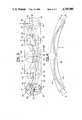
- the instrumentcomprises a control head forming a proximal end, an objective head forming a distal end and a tubular flexible shaft therebetween.
- the shaftcomprises a structural core made of a flexible material having a first longitudinal axis and a conduit means therewith.
- the conduit meansis, at least partially, offset from the first longitudinal axis such that the core has a first pre-determined length and the conduit means has a second pre-determined length.
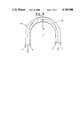
- FIG. 4is a diagrammatical view of a portion of the shaft in FIG. 1 having flexible section deflection.
- a light image received from the illuminated siteis conveyed back to an eyepiece assembly 10 by a second internal light carrier 46 (see FIG. 2) and suitable optical system, (not shown).
- a second internal light carrier 46see FIG. 2
- suitable optical system(not shown).
- the accessory passage or working channel 32extends from the control head 4 through the flexible shaft 8 to terminate in an open end in the objective head 6 and is accessible through an entry port 99 in a rotatable entry block 24 mounted on the housing 26 of the control head 4.
- a deflection conduit 30Located within the core 28, in the embodiment shown, are four conduits or passageways; a deflection conduit 30, a working conduit 32, and two fiber-optic conduits 34 and 36, which travel through the core 28 from a first end 37 (see FIG. 3) of the core 28 adjacent the control head 4 to a second end 38 (see FIG. 3) of the core 28 adjacent the objective head 6.
- the conduits 30, 32, 34, 36are substantially continuous between the two ends 37 and 38 of the core 28; however, some of their paths may be either straight, curved or even have a specific pattern.
- the deflection conduit 30is generally provided as a housing conduit for housing a deflection means.
- the working conduit 32is generally provided as the accessory passage or working channel for the instrument 2.
- the working channel 32is connected at one end to the entry port 99 in the rotatable entry block 24 (see FIG. 1) at the first end 37 of the core with the opposite end of the working channel 32 being connected at the second end 38 of the core 28 to a working channel conduit (not shown) in the objective head 6.
- the working conduit 32 of the core 28thus is capable of allowing fluids and instruments introduced at the control head 4 to pass through the flexible shaft 8 and exit the objective head 6 to access the target area.
- the two fiber-optic conduits 34 and 36are generally provided to house the two light carriers or bundles of light transmitting fibers 44 and 46. In the alternative, a single light bundle could be used in the instrument 2 or alternatively, any number of bundles.
- the first light carrier 44receives light from the external light carrier 18 at the light post/vent valve assembly 22. The first light carrier 44 travels through the control head 4 and through the conduit 34 of the core 28 to the objective head 6. The carrier 44 can thus provide light to the inspection site. A light image received from the illuminated site is conveyed back to the eyepieces assembly 10 by the second internal light carrier 46 which travels from the objective head 6 through the conduit 36 and control head 4 to the assembly 10.
- the core 28has an exterior cover 66.
- the cover 66in this embodiment, comprises a wire braid sheath 67 having an additional covering 69 of a flexible and resilient material, such as polymer material.
- the wire braid sheath 67can be made of any suitable material, such as stainless steel, and in this embodiment, helps to provide several functions for the shaft 8.
- the bonding of the braid 67 to the core 28stiffens the shaft 8 to give the shaft additional column strength to assist in insertion towards a target area and also prevents buckling.
- the outer covering 69may either comprise a separate cover which is connected to the wire sheath 67 or alternatively the outer cover 69 can be sprayed onto the sheath 67.
- any type of cover or torque stabilizer meanscan be used with the core 28 or the core 28 may be used without a sheath cover 66.
- the shaft 8, in the embodiment showncan have a shaft circumference at least as small as about ten (10) French or a diameter of about 3.33 mils.
- FIG. 3shows a diagrammatical view of the core 28 with conduit paths of the conduits 30, 34 and 36 shown.
- the path of the conduit 32has been omitted for the sake of clarity only.
- the conduits 30, 32, 34 and 36travel through the core 28 between the first end 37 and the second end 38.
- the conduits 30, 32, 34 and 36are substantially continuous; however, their paths are not straight.
- the paths of the conduits 30, 32, 34 and 36although maintained in a substantially constant orientation to each other, are spiralled about the core longitudinal axis as they travel from the first end 37 towards a region proximate the second end 38.
- Section Cshows the conduit orientation of the core 28 taken along line C in FIG. 3.
- the conduits 30, 32, 34 and 36have retained their orientation relative to each other, but once again the overall orientation of their position in the core has changed.
- the conduitsIn this position of the core 28 the conduits have rotated an additional 90 degrees counter-clockwise from the section at line D with the deflection conduit 30 located on the bottom and the working conduit 32 located on the top.
- the conduits 30, 32, 34 and 36continue to rotate as shown in sections B and A in a substantially uniform manner about the longitudinal axis until they reach a region proximate the second end 38 of the core 28.
- the conduitsare spiralled about the longitudinal axis several times between the first end 37 and a region proximate the second end 38.
- only the deflection conduit 30has a spiralled or non-straight path.
- the region proximate the second end 38, in this embodiment,is intended for use as the deflection section 12 of the instrument 2. For this reason, it is preferable to have the deflection conduit 30 in a substantially straight position proximate the distal end of the instrument 2 for proper deflection control of the distal end.
- the paths of the conduits 30, 32, 34 and 36may be continuously spiralled.
- a twist retention membermay optionally be connected to the core 28 to retain its twisted orientation and prevent the core from elastically returning to an untwisted or straight conduit position.
- the wire braid sheath 67 of the cover 66is attached to the core to retain the twist.
- the sheath 67is selectively bonded to the core 28 such that the region proximate the second end 38 of the core can untwist or straighten to allow for proper deflection control.
- the sheath 67is bonded to the objective head 6 and selectively to the core 28 by means of an adhesive or the like.
- the core 28can be manufactured without a twist such as by creating the non-straight channels by drilling or as the core is originally extruded.
- the coremay be fabricated such that deflection conduit 30 is relatively straight, but occupies a relatively large cross-section of the core with the deflection means contained in the conduit 30 in a non-straight manner.
- a combination of a straight conduit with a varying length and a relatively fixed length deflection meanswould cause the distal end of the instrument to involuntarily or uncontrollably deflect as the shaft was passed through a bend in a channel or twisted after reaching a target area. Therefore, a deflection means could not be used in the prior art without involuntarily or uncontrollable deflection in the distal end of the instrument. Therefore, the non-straight, or in this embodiment, spiralled, path of the deflection conduit 30 has been provided by the present invention to prevent the involuntary or uncontrolled deflection of the distal end.
- the channel 30 and the deflection cable 40are located in both the compressive section G and tensile section F at the bend in the shaft 8.
- the lengthening of the channel 30 along the expansion section Fis compensated for by the shortening of the channel 30 along the compression section G to help maintain a substantially uniform overall length of the channel 30. Because of the substantially uniform or constant overall length of the channel 30 created by the non-straight channel path, the length of the cable 40 and the length of the conduit 30 remain relatively equal even when the shaft is bent or is located in a bending channel path and twisted or torqued in order to rotationally move the objective head 6.
- the core 28is expanded along section F and compressed along section G. Because the conduit 30 is equally located in both sections F and G, the overall length of the conduit 30 remains relatively constant. Although the conduit 30 expands or lengthens in section F, the conduit 30 shortens in section G to thereby compensate for the bend or deflection of the flexible shaft 14 to retain a relatively constant conduit length. When the flexible section 14 is returned to a straight position the core 28 expands along section G and contracts along section F to retain the relatively constant length of the conduit 30.
- the conduitscan be spiralled or non-straight in the deflection section 12.
- the deflection compensation meanscan be applied to all the conduits or selective conduits.
Landscapes
- Physics & Mathematics (AREA)
- Health & Medical Sciences (AREA)
- Life Sciences & Earth Sciences (AREA)
- Optics & Photonics (AREA)
- Surgery (AREA)
- General Physics & Mathematics (AREA)
- Biomedical Technology (AREA)
- Molecular Biology (AREA)
- Pathology (AREA)
- Engineering & Computer Science (AREA)
- Nuclear Medicine, Radiotherapy & Molecular Imaging (AREA)
- Heart & Thoracic Surgery (AREA)
- Medical Informatics (AREA)
- Radiology & Medical Imaging (AREA)
- Animal Behavior & Ethology (AREA)
- General Health & Medical Sciences (AREA)
- Public Health (AREA)
- Veterinary Medicine (AREA)
- Biophysics (AREA)
- Astronomy & Astrophysics (AREA)
- Endoscopes (AREA)
Abstract
Description
Claims (18)
Priority Applications (1)
| Application Number | Priority Date | Filing Date | Title |
|---|---|---|---|
| US07/047,750US4745908A (en) | 1987-05-08 | 1987-05-08 | Inspection instrument fexible shaft having deflection compensation means |
Applications Claiming Priority (1)
| Application Number | Priority Date | Filing Date | Title |
|---|---|---|---|
| US07/047,750US4745908A (en) | 1987-05-08 | 1987-05-08 | Inspection instrument fexible shaft having deflection compensation means |
Publications (1)
| Publication Number | Publication Date |
|---|---|
| US4745908Atrue US4745908A (en) | 1988-05-24 |
Family
ID=21950752
Family Applications (1)
| Application Number | Title | Priority Date | Filing Date |
|---|---|---|---|
| US07/047,750Expired - LifetimeUS4745908A (en) | 1987-05-08 | 1987-05-08 | Inspection instrument fexible shaft having deflection compensation means |
Country Status (1)
| Country | Link |
|---|---|
| US (1) | US4745908A (en) |
Cited By (142)
| Publication number | Priority date | Publication date | Assignee | Title |
|---|---|---|---|---|
| US4870951A (en)* | 1987-08-04 | 1989-10-03 | Olympus Optical Co., Ltd. | Endoscope having varying diameter contents in the insertable part |
| US4902129A (en)* | 1988-09-06 | 1990-02-20 | Schott Fiber Optics | Orientation indicator for a flexible fiberscope or endoscope including method of manufacture |
| US5279281A (en)* | 1990-09-14 | 1994-01-18 | Harvey James C | Single-handed fibre-optic flexible laryngoscope |
| US5399164A (en)* | 1992-11-02 | 1995-03-21 | Catheter Imaging Systems | Catheter having a multiple durometer |
| US5772576A (en)* | 1995-12-11 | 1998-06-30 | Embro Vascular L.L.C. | Apparatus and method for vein removal |
| USD398986S (en) | 1996-01-16 | 1998-09-29 | Catheter Imaging Systems, Inc. | Handle interface for steerable catheter |
| US5846221A (en)* | 1996-02-09 | 1998-12-08 | Catheter Imaging Systems, Inc. | Steerable catheter having disposable module and sterilizable handle and method of connecting same |
| US5857996A (en)* | 1992-07-06 | 1999-01-12 | Catheter Imaging Systems | Method of epidermal surgery |
| USRE36043E (en)* | 1992-10-02 | 1999-01-12 | Embro Vascular, L.L.C. | Endoscope and method for vein removal |
| USD405881S (en) | 1996-01-16 | 1999-02-16 | Catheter Imaging Systems, Inc. | Handle for steerable catheter |
| US6007531A (en)* | 1995-11-21 | 1999-12-28 | Catheter Imaging Systems, Inc. | Steerable catheter having disposable module and sterilizable handle and method of connecting same |
| US6023325A (en)* | 1995-11-02 | 2000-02-08 | Reflex Instrument Ab | Arrangement for sensing elastic deformation in a tool stem in a machine tool |
| US6213940B1 (en) | 1996-04-26 | 2001-04-10 | United States Surgical Corporation | Surgical retractor including coil spring suture mount |
| US6238389B1 (en) | 1997-09-30 | 2001-05-29 | Boston Scientific Corporation | Deflectable interstitial ablation device |
| JP3196951B2 (en) | 1993-12-17 | 2001-08-06 | オリンパス光学工業株式会社 | Cover-type endoscope |
| US6565508B2 (en) | 1998-01-23 | 2003-05-20 | United States Surgical Corporation | Surgical instrument |
| US20030216619A1 (en)* | 2001-07-13 | 2003-11-20 | Paul Scirica | Surgical instrument |
| US20040138529A1 (en)* | 2003-01-15 | 2004-07-15 | Usgi Medical Corp. | Endoluminal tool deployment system |
| US20040215064A1 (en)* | 1998-01-23 | 2004-10-28 | Person Wayne C. | Surgical instrument holder |
| US20050273125A1 (en)* | 2004-05-13 | 2005-12-08 | Opie John C | Percutaneous vein harvester with shielded blade |
| US20060173243A1 (en)* | 2003-09-05 | 2006-08-03 | Olympus Corporation | Endoscope |
| US20070005084A1 (en)* | 2004-06-16 | 2007-01-04 | Clague Cynthia T | Minimally invasive coring vein harvester |
| US20080132762A1 (en)* | 2006-12-04 | 2008-06-05 | University Of Washington | Flexible endoscope tip bending mechanism using optical fiber as compression member |
| US20080132834A1 (en)* | 2006-12-04 | 2008-06-05 | University Of Washington | Flexible endoscope tip bending mechanism using optical fibers as tension members |
| US20080161841A1 (en)* | 2006-10-16 | 2008-07-03 | Clague Cynthia T | Cutting device and method of vessel harvesting |
| US20090192355A1 (en)* | 2008-01-28 | 2009-07-30 | Mauricio Mejia | Scope for managing difficult pathways and method to improve visibility of the same |
| US20100094090A1 (en)* | 2008-01-28 | 2010-04-15 | Mauricio Mejia | Self-cleaning wireless video stylet with display mounted to laryngoscope blade and method for using the same |
| US7867163B2 (en) | 1998-06-22 | 2011-01-11 | Maquet Cardiovascular Llc | Instrument and method for remotely manipulating a tissue structure |
| US20110009863A1 (en)* | 2009-07-10 | 2011-01-13 | Tyco Healthcare Group Lp | Shaft Constructions for Medical Devices with an Articulating Tip |
| US7938842B1 (en) | 1998-08-12 | 2011-05-10 | Maquet Cardiovascular Llc | Tissue dissector apparatus |
| US7955340B2 (en) | 1999-06-25 | 2011-06-07 | Usgi Medical, Inc. | Apparatus and methods for forming and securing gastrointestinal tissue folds |
| US7972265B1 (en) | 1998-06-22 | 2011-07-05 | Maquet Cardiovascular, Llc | Device and method for remote vessel ligation |
| US7981133B2 (en) | 1995-07-13 | 2011-07-19 | Maquet Cardiovascular, Llc | Tissue dissection method |
| US8216260B2 (en) | 2002-12-11 | 2012-07-10 | Usgi Medical, Inc. | Apparatus and methods for forming and securing gastrointestinal tissue folds |
| US8241210B2 (en) | 1998-06-22 | 2012-08-14 | Maquet Cardiovascular Llc | Vessel retractor |
| WO2015061756A1 (en) | 2013-10-24 | 2015-04-30 | Auris Surgical Robotics, Inc. | System for robotic-assisted endolumenal surgery and related methods |
| US9265514B2 (en) | 2012-04-17 | 2016-02-23 | Miteas Ltd. | Manipulator for grasping tissue |
| US20160058267A1 (en)* | 2008-12-10 | 2016-03-03 | Ambu A/S | Endoscope bending section control mechanism |
| EP3042711A1 (en) | 2008-07-18 | 2016-07-13 | Clarcor INC. | Multi-component filter media with nanofiber attachment |
| CN105828738A (en)* | 2013-12-20 | 2016-08-03 | 奥林巴斯株式会社 | Guide member for flexible manipulator and flexible manipulator |
| US9840266B2 (en) | 2013-10-09 | 2017-12-12 | Glidemachines Llc | Apparatus and method for towing a load by a person |
| US10080576B2 (en) | 2013-03-08 | 2018-09-25 | Auris Health, Inc. | Method, apparatus, and a system for facilitating bending of an instrument in a surgical or medical robotic environment |
| US10130427B2 (en) | 2010-09-17 | 2018-11-20 | Auris Health, Inc. | Systems and methods for positioning an elongate member inside a body |
| US10149720B2 (en) | 2013-03-08 | 2018-12-11 | Auris Health, Inc. | Method, apparatus, and a system for facilitating bending of an instrument in a surgical or medical robotic environment |
| EP3305163A4 (en)* | 2015-05-28 | 2019-02-06 | Olympus Corporation | Sheath member, manipulator, and manipulator system |
| US10213264B2 (en) | 2013-03-14 | 2019-02-26 | Auris Health, Inc. | Catheter tension sensing |
| US10299770B2 (en) | 2006-06-01 | 2019-05-28 | Maquet Cardiovascular Llc | Endoscopic vessel harvesting system components |
| US10376672B2 (en) | 2013-03-15 | 2019-08-13 | Auris Health, Inc. | Catheter insertion system and method of fabrication |
| US10398518B2 (en) | 2014-07-01 | 2019-09-03 | Auris Health, Inc. | Articulating flexible endoscopic tool with roll capabilities |
| US10454347B2 (en) | 2016-04-29 | 2019-10-22 | Auris Health, Inc. | Compact height torque sensing articulation axis assembly |
| US10463439B2 (en) | 2016-08-26 | 2019-11-05 | Auris Health, Inc. | Steerable catheter with shaft load distributions |
| US10470830B2 (en) | 2017-12-11 | 2019-11-12 | Auris Health, Inc. | Systems and methods for instrument based insertion architectures |
| US10478595B2 (en) | 2013-03-07 | 2019-11-19 | Auris Health, Inc. | Infinitely rotatable tool with finite rotating drive shafts |
| US10493241B2 (en) | 2014-07-01 | 2019-12-03 | Auris Health, Inc. | Apparatuses and methods for monitoring tendons of steerable catheters |
| US10493239B2 (en) | 2013-03-14 | 2019-12-03 | Auris Health, Inc. | Torque-based catheter articulation |
| US10507012B2 (en) | 2000-11-17 | 2019-12-17 | Maquet Cardiovascular Llc | Vein harvesting system and method |
| US10524866B2 (en) | 2018-03-28 | 2020-01-07 | Auris Health, Inc. | Systems and methods for registration of location sensors |
| US10524867B2 (en) | 2013-03-15 | 2020-01-07 | Auris Health, Inc. | Active drive mechanism for simultaneous rotation and translation |
| US10531864B2 (en) | 2013-03-15 | 2020-01-14 | Auris Health, Inc. | System and methods for tracking robotically controlled medical instruments |
| US20200016557A1 (en)* | 2017-04-07 | 2020-01-16 | Andre Brüning | Supply line guide for a vacuum processing system, use of a supply line guide and processing system |
| US10539478B2 (en) | 2017-10-10 | 2020-01-21 | Auris Health, Inc. | Detection of misalignment of robotic arms |
| US10543047B2 (en) | 2013-03-15 | 2020-01-28 | Auris Health, Inc. | Remote catheter manipulator |
| US10543048B2 (en) | 2016-12-28 | 2020-01-28 | Auris Health, Inc. | Flexible instrument insertion using an adaptive insertion force threshold |
| US10556092B2 (en) | 2013-03-14 | 2020-02-11 | Auris Health, Inc. | Active drives for robotic catheter manipulators |
| US10569052B2 (en) | 2014-05-15 | 2020-02-25 | Auris Health, Inc. | Anti-buckling mechanisms for catheters |
| CN110868903A (en)* | 2017-06-30 | 2020-03-06 | 奥瑞斯健康公司 | System and method for medical device compression compensation |
| US10631949B2 (en) | 2015-09-09 | 2020-04-28 | Auris Health, Inc. | Instrument device manipulator with back-mounted tool attachment mechanism |
| US10667720B2 (en) | 2011-07-29 | 2020-06-02 | Auris Health, Inc. | Apparatus and methods for fiber integration and registration |
| US10667871B2 (en) | 2014-09-30 | 2020-06-02 | Auris Health, Inc. | Configurable robotic surgical system with virtual rail and flexible endoscope |
| US10682189B2 (en) | 2016-08-31 | 2020-06-16 | Auris Health, Inc. | Length conservative surgical instrument |
| US10687903B2 (en) | 2013-03-14 | 2020-06-23 | Auris Health, Inc. | Active drive for robotic catheter manipulators |
| US10695536B2 (en) | 2001-02-15 | 2020-06-30 | Auris Health, Inc. | Catheter driver system |
| US10716461B2 (en) | 2017-05-17 | 2020-07-21 | Auris Health, Inc. | Exchangeable working channel |
| US10765487B2 (en) | 2018-09-28 | 2020-09-08 | Auris Health, Inc. | Systems and methods for docking medical instruments |
| US10765303B2 (en) | 2018-02-13 | 2020-09-08 | Auris Health, Inc. | System and method for driving medical instrument |
| US10792112B2 (en) | 2013-03-15 | 2020-10-06 | Auris Health, Inc. | Active drive mechanism with finite range of motion |
| US10792464B2 (en) | 2014-07-01 | 2020-10-06 | Auris Health, Inc. | Tool and method for using surgical endoscope with spiral lumens |
| US10796432B2 (en) | 2015-09-18 | 2020-10-06 | Auris Health, Inc. | Navigation of tubular networks |
| US10806535B2 (en) | 2015-11-30 | 2020-10-20 | Auris Health, Inc. | Robot-assisted driving systems and methods |
| US10813539B2 (en) | 2016-09-30 | 2020-10-27 | Auris Health, Inc. | Automated calibration of surgical instruments with pull wires |
| US10820954B2 (en) | 2018-06-27 | 2020-11-03 | Auris Health, Inc. | Alignment and attachment systems for medical instruments |
| US10820947B2 (en) | 2018-09-28 | 2020-11-03 | Auris Health, Inc. | Devices, systems, and methods for manually and robotically driving medical instruments |
| US10820952B2 (en) | 2013-03-15 | 2020-11-03 | Auris Heath, Inc. | Rotational support for an elongate member |
| US10827913B2 (en) | 2018-03-28 | 2020-11-10 | Auris Health, Inc. | Systems and methods for displaying estimated location of instrument |
| US10888386B2 (en) | 2018-01-17 | 2021-01-12 | Auris Health, Inc. | Surgical robotics systems with improved robotic arms |
| US10898276B2 (en) | 2018-08-07 | 2021-01-26 | Auris Health, Inc. | Combining strain-based shape sensing with catheter control |
| US10898286B2 (en) | 2018-05-31 | 2021-01-26 | Auris Health, Inc. | Path-based navigation of tubular networks |
| US10898275B2 (en) | 2018-05-31 | 2021-01-26 | Auris Health, Inc. | Image-based airway analysis and mapping |
| US10905499B2 (en) | 2018-05-30 | 2021-02-02 | Auris Health, Inc. | Systems and methods for location sensor-based branch prediction |
| US10912924B2 (en) | 2014-03-24 | 2021-02-09 | Auris Health, Inc. | Systems and devices for catheter driving instinctiveness |
| US10987179B2 (en) | 2017-12-06 | 2021-04-27 | Auris Health, Inc. | Systems and methods to correct for uncommanded instrument roll |
| US11020016B2 (en) | 2013-05-30 | 2021-06-01 | Auris Health, Inc. | System and method for displaying anatomy and devices on a movable display |
| US11026758B2 (en) | 2017-06-28 | 2021-06-08 | Auris Health, Inc. | Medical robotics systems implementing axis constraints during actuation of one or more motorized joints |
| WO2021112067A1 (en)* | 2019-12-02 | 2021-06-10 | 朝日インテック株式会社 | Catheter |
| US11051681B2 (en) | 2010-06-24 | 2021-07-06 | Auris Health, Inc. | Methods and devices for controlling a shapeable medical device |
| US11058493B2 (en) | 2017-10-13 | 2021-07-13 | Auris Health, Inc. | Robotic system configured for navigation path tracing |
| US11109920B2 (en) | 2018-03-28 | 2021-09-07 | Auris Health, Inc. | Medical instruments with variable bending stiffness profiles |
| US11141048B2 (en) | 2015-06-26 | 2021-10-12 | Auris Health, Inc. | Automated endoscope calibration |
| US11147637B2 (en) | 2012-05-25 | 2021-10-19 | Auris Health, Inc. | Low friction instrument driver interface for robotic systems |
| US11147633B2 (en) | 2019-08-30 | 2021-10-19 | Auris Health, Inc. | Instrument image reliability systems and methods |
| US11160615B2 (en) | 2017-12-18 | 2021-11-02 | Auris Health, Inc. | Methods and systems for instrument tracking and navigation within luminal networks |
| US11166627B2 (en) | 2018-01-26 | 2021-11-09 | Ambu A/S | Method for fixation of a wire portion of an endoscope, and an endoscope |
| US11179212B2 (en) | 2018-09-26 | 2021-11-23 | Auris Health, Inc. | Articulating medical instruments |
| US11207141B2 (en) | 2019-08-30 | 2021-12-28 | Auris Health, Inc. | Systems and methods for weight-based registration of location sensors |
| US11213363B2 (en) | 2013-03-14 | 2022-01-04 | Auris Health, Inc. | Catheter tension sensing |
| US11241203B2 (en) | 2013-03-13 | 2022-02-08 | Auris Health, Inc. | Reducing measurement sensor error |
| US11241559B2 (en) | 2016-08-29 | 2022-02-08 | Auris Health, Inc. | Active drive for guidewire manipulation |
| US11278703B2 (en) | 2014-04-21 | 2022-03-22 | Auris Health, Inc. | Devices, systems, and methods for controlling active drive systems |
| US11278357B2 (en) | 2017-06-23 | 2022-03-22 | Auris Health, Inc. | Robotic systems for determining an angular degree of freedom of a medical device in luminal networks |
| US11291355B2 (en) | 2018-01-19 | 2022-04-05 | Ambu A/S | Method for fixation of a wire portion of an endoscope, and an endoscope |
| US11298195B2 (en) | 2019-12-31 | 2022-04-12 | Auris Health, Inc. | Anatomical feature identification and targeting |
| US11382650B2 (en) | 2015-10-30 | 2022-07-12 | Auris Health, Inc. | Object capture with a basket |
| US11426095B2 (en) | 2013-03-15 | 2022-08-30 | Auris Health, Inc. | Flexible instrument localization from both remote and elongation sensors |
| US11439419B2 (en) | 2019-12-31 | 2022-09-13 | Auris Health, Inc. | Advanced basket drive mode |
| US11464586B2 (en) | 2009-04-29 | 2022-10-11 | Auris Health, Inc. | Flexible and steerable elongate instruments with shape control and support elements |
| US11490782B2 (en) | 2017-03-31 | 2022-11-08 | Auris Health, Inc. | Robotic systems for navigation of luminal networks that compensate for physiological noise |
| US11504187B2 (en) | 2013-03-15 | 2022-11-22 | Auris Health, Inc. | Systems and methods for localizing, tracking and/or controlling medical instruments |
| US11503986B2 (en) | 2018-05-31 | 2022-11-22 | Auris Health, Inc. | Robotic systems and methods for navigation of luminal network that detect physiological noise |
| US11510736B2 (en) | 2017-12-14 | 2022-11-29 | Auris Health, Inc. | System and method for estimating instrument location |
| US11529129B2 (en) | 2017-05-12 | 2022-12-20 | Auris Health, Inc. | Biopsy apparatus and system |
| US11534247B2 (en) | 2017-06-28 | 2022-12-27 | Auris Health, Inc. | Instrument insertion compensation |
| US11534249B2 (en) | 2015-10-30 | 2022-12-27 | Auris Health, Inc. | Process for percutaneous operations |
| US11553833B2 (en) | 2017-03-08 | 2023-01-17 | Ambu A/S | Handle for an endoscope |
| US11571229B2 (en) | 2015-10-30 | 2023-02-07 | Auris Health, Inc. | Basket apparatus |
| US11602372B2 (en) | 2019-12-31 | 2023-03-14 | Auris Health, Inc. | Alignment interfaces for percutaneous access |
| US11617627B2 (en) | 2019-03-29 | 2023-04-04 | Auris Health, Inc. | Systems and methods for optical strain sensing in medical instruments |
| US11638618B2 (en) | 2019-03-22 | 2023-05-02 | Auris Health, Inc. | Systems and methods for aligning inputs on medical instruments |
| US11642014B2 (en) | 2017-03-08 | 2023-05-09 | Ambu A/S | Handle for an endoscope |
| US11660147B2 (en) | 2019-12-31 | 2023-05-30 | Auris Health, Inc. | Alignment techniques for percutaneous access |
| US11717147B2 (en) | 2019-08-15 | 2023-08-08 | Auris Health, Inc. | Medical device having multiple bending sections |
| US11737845B2 (en) | 2019-09-30 | 2023-08-29 | Auris Inc. | Medical instrument with a capstan |
| US11771309B2 (en) | 2016-12-28 | 2023-10-03 | Auris Health, Inc. | Detecting endolumenal buckling of flexible instruments |
| US11819636B2 (en) | 2015-03-30 | 2023-11-21 | Auris Health, Inc. | Endoscope pull wire electrical circuit |
| US11850008B2 (en) | 2017-10-13 | 2023-12-26 | Auris Health, Inc. | Image-based branch detection and mapping for navigation |
| US11896330B2 (en) | 2019-08-15 | 2024-02-13 | Auris Health, Inc. | Robotic medical system having multiple medical instruments |
| US11925774B2 (en) | 2012-11-28 | 2024-03-12 | Auris Health, Inc. | Method of anchoring pullwire directly articulatable region in catheter |
| US11950872B2 (en) | 2019-12-31 | 2024-04-09 | Auris Health, Inc. | Dynamic pulley system |
| CN117984348A (en)* | 2024-04-03 | 2024-05-07 | 江苏科技大学 | Cable-driven soft mechanical arm |
| US11986257B2 (en) | 2018-12-28 | 2024-05-21 | Auris Health, Inc. | Medical instrument with articulable segment |
| US12076100B2 (en) | 2018-09-28 | 2024-09-03 | Auris Health, Inc. | Robotic systems and methods for concomitant endoscopic and percutaneous medical procedures |
| WO2025026670A1 (en) | 2023-07-28 | 2025-02-06 | Fortimedix Assets Ii B.V. | Bendable tube with path length compensation of steering wires |
| US12414686B2 (en) | 2020-03-30 | 2025-09-16 | Auris Health, Inc. | Endoscopic anatomical feature tracking |
Citations (8)
| Publication number | Priority date | Publication date | Assignee | Title |
|---|---|---|---|---|
| US1958656A (en)* | 1933-12-28 | 1934-05-15 | Buerger Leo | Cystoscope and the like |
| US2120996A (en)* | 1936-10-09 | 1938-06-21 | Wappler Frederick Charles | Cystoscopic armamentarium |
| US3368552A (en)* | 1965-11-26 | 1968-02-13 | Medizintechnik Leipzig Veb | Endoscope device |
| US3610231A (en)* | 1967-07-21 | 1971-10-05 | Olympus Optical Co | Endoscope |
| US3792701A (en)* | 1970-11-03 | 1974-02-19 | E Kloz | Neutralising device for urinary, ureteral and kidney pelvis caluli |
| US3918438A (en)* | 1973-04-16 | 1975-11-11 | Olympus Optical Co | Endoscope capable of changing over the directions of visual field |
| US4530568A (en)* | 1982-11-19 | 1985-07-23 | American Hospital Supply Corporation | Flexible optical inspection system |
| US4616631A (en)* | 1979-02-10 | 1986-10-14 | Kabushiki Kaisha Medos Kenkyusho | Flexible pipe assembly for endoscope |
- 1987
- 1987-05-08USUS07/047,750patent/US4745908A/ennot_activeExpired - Lifetime
Patent Citations (8)
| Publication number | Priority date | Publication date | Assignee | Title |
|---|---|---|---|---|
| US1958656A (en)* | 1933-12-28 | 1934-05-15 | Buerger Leo | Cystoscope and the like |
| US2120996A (en)* | 1936-10-09 | 1938-06-21 | Wappler Frederick Charles | Cystoscopic armamentarium |
| US3368552A (en)* | 1965-11-26 | 1968-02-13 | Medizintechnik Leipzig Veb | Endoscope device |
| US3610231A (en)* | 1967-07-21 | 1971-10-05 | Olympus Optical Co | Endoscope |
| US3792701A (en)* | 1970-11-03 | 1974-02-19 | E Kloz | Neutralising device for urinary, ureteral and kidney pelvis caluli |
| US3918438A (en)* | 1973-04-16 | 1975-11-11 | Olympus Optical Co | Endoscope capable of changing over the directions of visual field |
| US4616631A (en)* | 1979-02-10 | 1986-10-14 | Kabushiki Kaisha Medos Kenkyusho | Flexible pipe assembly for endoscope |
| US4530568A (en)* | 1982-11-19 | 1985-07-23 | American Hospital Supply Corporation | Flexible optical inspection system |
Cited By (286)
| Publication number | Priority date | Publication date | Assignee | Title |
|---|---|---|---|---|
| US4870951A (en)* | 1987-08-04 | 1989-10-03 | Olympus Optical Co., Ltd. | Endoscope having varying diameter contents in the insertable part |
| US4902129A (en)* | 1988-09-06 | 1990-02-20 | Schott Fiber Optics | Orientation indicator for a flexible fiberscope or endoscope including method of manufacture |
| US5279281A (en)* | 1990-09-14 | 1994-01-18 | Harvey James C | Single-handed fibre-optic flexible laryngoscope |
| US5857996A (en)* | 1992-07-06 | 1999-01-12 | Catheter Imaging Systems | Method of epidermal surgery |
| US6464682B1 (en) | 1992-07-06 | 2002-10-15 | Catheter Imaging Systems, Inc. | Method of epidural surgery |
| US6470209B2 (en) | 1992-07-06 | 2002-10-22 | Catheter Imaging Systems, Inc. | System for enhancing visibility in the epidural space |
| US6010493A (en)* | 1992-07-06 | 2000-01-04 | Catheter Imaging Systems | Method of epidural surgery |
| US6925323B2 (en) | 1992-07-06 | 2005-08-02 | Phillip Jack Snoke | System for enhancing visibility in the epidural space |
| USRE36043E (en)* | 1992-10-02 | 1999-01-12 | Embro Vascular, L.L.C. | Endoscope and method for vein removal |
| US5624397A (en)* | 1992-11-02 | 1997-04-29 | Snoke; Phillip J. | Catheter having a multiple durometer |
| US5542924A (en)* | 1992-11-02 | 1996-08-06 | Catheter Imaging Systems | Method of forming a catheter having a multiple durometer |
| US5399164A (en)* | 1992-11-02 | 1995-03-21 | Catheter Imaging Systems | Catheter having a multiple durometer |
| JP3196951B2 (en) | 1993-12-17 | 2001-08-06 | オリンパス光学工業株式会社 | Cover-type endoscope |
| US7981133B2 (en) | 1995-07-13 | 2011-07-19 | Maquet Cardiovascular, Llc | Tissue dissection method |
| US6023325A (en)* | 1995-11-02 | 2000-02-08 | Reflex Instrument Ab | Arrangement for sensing elastic deformation in a tool stem in a machine tool |
| US5860953A (en)* | 1995-11-21 | 1999-01-19 | Catheter Imaging Systems, Inc. | Steerable catheter having disposable module and sterilizable handle and method of connecting same |
| US6007531A (en)* | 1995-11-21 | 1999-12-28 | Catheter Imaging Systems, Inc. | Steerable catheter having disposable module and sterilizable handle and method of connecting same |
| US6017322A (en)* | 1995-11-21 | 2000-01-25 | Catheter Imaging Systems, Inc. | Steerable catheter having disposable module and sterilizable handle and method of connecting same |
| US7066875B2 (en) | 1995-12-11 | 2006-06-27 | Cardio Thoracic Systems, Inc. | Apparatus and method for vein removal |
| US5772576A (en)* | 1995-12-11 | 1998-06-30 | Embro Vascular L.L.C. | Apparatus and method for vein removal |
| US6428468B1 (en) | 1995-12-11 | 2002-08-06 | Cardiothoracic Systems, Inc. | Apparatus and method for vein removal |
| US6071232A (en)* | 1995-12-11 | 2000-06-06 | Embro Vascular L.L.C. | Apparatus for vein removal |
| USD398986S (en) | 1996-01-16 | 1998-09-29 | Catheter Imaging Systems, Inc. | Handle interface for steerable catheter |
| USD405881S (en) | 1996-01-16 | 1999-02-16 | Catheter Imaging Systems, Inc. | Handle for steerable catheter |
| US5846221A (en)* | 1996-02-09 | 1998-12-08 | Catheter Imaging Systems, Inc. | Steerable catheter having disposable module and sterilizable handle and method of connecting same |
| US6537212B2 (en) | 1996-04-26 | 2003-03-25 | United States Surgical Corporation | Surgical retractor |
| US6213940B1 (en) | 1996-04-26 | 2001-04-10 | United States Surgical Corporation | Surgical retractor including coil spring suture mount |
| US6352534B1 (en) | 1997-09-30 | 2002-03-05 | Boston Scientific Corporation | Deflectable interstitial ablation device |
| US6238389B1 (en) | 1997-09-30 | 2001-05-29 | Boston Scientific Corporation | Deflectable interstitial ablation device |
| US6482203B2 (en) | 1997-09-30 | 2002-11-19 | Scimed Life Systems, Inc. | Deflectable interstitial ablation device |
| US7909821B2 (en) | 1997-09-30 | 2011-03-22 | Boston Scientific Scimed, Inc. | Deflectable interstitial ablation device |
| US20040215064A1 (en)* | 1998-01-23 | 2004-10-28 | Person Wayne C. | Surgical instrument holder |
| US7744530B2 (en) | 1998-01-23 | 2010-06-29 | Tyco Healthcare Group Lp | Surgical instrument holder |
| US6565508B2 (en) | 1998-01-23 | 2003-05-20 | United States Surgical Corporation | Surgical instrument |
| US7294104B2 (en) | 1998-01-23 | 2007-11-13 | United States Surgical Corporation | Surgical instrument holder |
| US8241210B2 (en) | 1998-06-22 | 2012-08-14 | Maquet Cardiovascular Llc | Vessel retractor |
| US7972265B1 (en) | 1998-06-22 | 2011-07-05 | Maquet Cardiovascular, Llc | Device and method for remote vessel ligation |
| US7867163B2 (en) | 1998-06-22 | 2011-01-11 | Maquet Cardiovascular Llc | Instrument and method for remotely manipulating a tissue structure |
| US7938842B1 (en) | 1998-08-12 | 2011-05-10 | Maquet Cardiovascular Llc | Tissue dissector apparatus |
| US8986335B2 (en) | 1998-08-12 | 2015-03-24 | Maquet Cardiovascular Llc | Tissue dissector apparatus and method |
| US9730782B2 (en) | 1998-08-12 | 2017-08-15 | Maquet Cardiovascular Llc | Vessel harvester |
| US9700398B2 (en) | 1998-08-12 | 2017-07-11 | Maquet Cardiovascular Llc | Vessel harvester |
| US8460331B2 (en) | 1998-08-12 | 2013-06-11 | Maquet Cardiovascular, Llc | Tissue dissector apparatus and method |
| US7955340B2 (en) | 1999-06-25 | 2011-06-07 | Usgi Medical, Inc. | Apparatus and methods for forming and securing gastrointestinal tissue folds |
| US10507012B2 (en) | 2000-11-17 | 2019-12-17 | Maquet Cardiovascular Llc | Vein harvesting system and method |
| US10695536B2 (en) | 2001-02-15 | 2020-06-30 | Auris Health, Inc. | Catheter driver system |
| US20030216619A1 (en)* | 2001-07-13 | 2003-11-20 | Paul Scirica | Surgical instrument |
| US7137949B2 (en) | 2001-07-13 | 2006-11-21 | United States Surgical Corporation | Surgical instrument |
| US8216260B2 (en) | 2002-12-11 | 2012-07-10 | Usgi Medical, Inc. | Apparatus and methods for forming and securing gastrointestinal tissue folds |
| US20040138529A1 (en)* | 2003-01-15 | 2004-07-15 | Usgi Medical Corp. | Endoluminal tool deployment system |
| US7918845B2 (en) | 2003-01-15 | 2011-04-05 | Usgi Medical, Inc. | Endoluminal tool deployment system |
| US20060173243A1 (en)* | 2003-09-05 | 2006-08-03 | Olympus Corporation | Endoscope |
| US8292803B2 (en)* | 2003-09-05 | 2012-10-23 | Olympus Corporation | Endoscope |
| US20100305594A1 (en)* | 2004-05-13 | 2010-12-02 | Scottsdale Medical Devices, Inc. | Percutaneous vein harvester with shielded blade |
| US20050273125A1 (en)* | 2004-05-13 | 2005-12-08 | Opie John C | Percutaneous vein harvester with shielded blade |
| US20070005084A1 (en)* | 2004-06-16 | 2007-01-04 | Clague Cynthia T | Minimally invasive coring vein harvester |
| US8480696B2 (en) | 2004-06-16 | 2013-07-09 | Medtronic, Inc. | Minimally invasive coring vein harvester |
| US10299770B2 (en) | 2006-06-01 | 2019-05-28 | Maquet Cardiovascular Llc | Endoscopic vessel harvesting system components |
| US11141055B2 (en) | 2006-06-01 | 2021-10-12 | Maquet Cardiovascular Llc | Endoscopic vessel harvesting system components |
| US11134835B2 (en) | 2006-06-01 | 2021-10-05 | Maquet Cardiovascular Llc | Endoscopic vessel harvesting system components |
| US20100114136A1 (en)* | 2006-10-16 | 2010-05-06 | Scottsdale Medical Devices, Inc. | Cutting device and method of vessel harvesting |
| US20080161843A1 (en)* | 2006-10-16 | 2008-07-03 | Clague Cynthia T | Vessel support device and method of vessel harvesting |
| US20080167669A1 (en)* | 2006-10-16 | 2008-07-10 | Clague Cynthia T | Vessel tensioning handle and method of vessel harvesting |
| US20100121362A1 (en)* | 2006-10-16 | 2010-05-13 | Scottsdale Medical Devices, Inc. | Vessel support device and method of vessel harvesting |
| US20080161841A1 (en)* | 2006-10-16 | 2008-07-03 | Clague Cynthia T | Cutting device and method of vessel harvesting |
| US8096943B2 (en)* | 2006-12-04 | 2012-01-17 | University Of Washington Through Its Center For Commercialization | Flexible endoscope tip bending mechanism using optical fiber as compression member |
| US20080132762A1 (en)* | 2006-12-04 | 2008-06-05 | University Of Washington | Flexible endoscope tip bending mechanism using optical fiber as compression member |
| US20080132834A1 (en)* | 2006-12-04 | 2008-06-05 | University Of Washington | Flexible endoscope tip bending mechanism using optical fibers as tension members |
| US20100094090A1 (en)* | 2008-01-28 | 2010-04-15 | Mauricio Mejia | Self-cleaning wireless video stylet with display mounted to laryngoscope blade and method for using the same |
| US20090192355A1 (en)* | 2008-01-28 | 2009-07-30 | Mauricio Mejia | Scope for managing difficult pathways and method to improve visibility of the same |
| US8888683B2 (en) | 2008-01-28 | 2014-11-18 | Mauricio Mejia | Modifications in endoscope apparatus, using fluid and gas dynamics, and methods for improving visibility during endoscopy |
| EP3042711A1 (en) | 2008-07-18 | 2016-07-13 | Clarcor INC. | Multi-component filter media with nanofiber attachment |
| US20160058267A1 (en)* | 2008-12-10 | 2016-03-03 | Ambu A/S | Endoscope bending section control mechanism |
| US10149605B2 (en)* | 2008-12-10 | 2018-12-11 | Ambu A/S | Endoscope bending section control mechanism |
| US10165931B2 (en) | 2008-12-10 | 2019-01-01 | Ambu A/S | Endoscope bending section control mechanism |
| US10624529B2 (en) | 2008-12-10 | 2020-04-21 | Ambu A/S | Endoscope bending section control mechanism |
| US11464586B2 (en) | 2009-04-29 | 2022-10-11 | Auris Health, Inc. | Flexible and steerable elongate instruments with shape control and support elements |
| US20110009863A1 (en)* | 2009-07-10 | 2011-01-13 | Tyco Healthcare Group Lp | Shaft Constructions for Medical Devices with an Articulating Tip |
| US11857156B2 (en) | 2010-06-24 | 2024-01-02 | Auris Health, Inc. | Methods and devices for controlling a shapeable medical device |
| US11051681B2 (en) | 2010-06-24 | 2021-07-06 | Auris Health, Inc. | Methods and devices for controlling a shapeable medical device |
| US10555780B2 (en) | 2010-09-17 | 2020-02-11 | Auris Health, Inc. | Systems and methods for positioning an elongate member inside a body |
| US10130427B2 (en) | 2010-09-17 | 2018-11-20 | Auris Health, Inc. | Systems and methods for positioning an elongate member inside a body |
| US11213356B2 (en) | 2010-09-17 | 2022-01-04 | Auris Health, Inc. | Systems and methods for positioning an elongate member inside a body |
| US12310669B2 (en) | 2010-09-17 | 2025-05-27 | Auris Health, Inc. | Systems and methods for positioning an elongate member inside a body |
| US10667720B2 (en) | 2011-07-29 | 2020-06-02 | Auris Health, Inc. | Apparatus and methods for fiber integration and registration |
| US11419518B2 (en) | 2011-07-29 | 2022-08-23 | Auris Health, Inc. | Apparatus and methods for fiber integration and registration |
| US9265514B2 (en) | 2012-04-17 | 2016-02-23 | Miteas Ltd. | Manipulator for grasping tissue |
| US12207831B2 (en) | 2012-04-17 | 2025-01-28 | A-Base Korlatolt Felelossegu Tarsasag | Manipulator for grasping tissue |
| US11633203B2 (en) | 2012-04-17 | 2023-04-25 | A-Base Korlatolt Felelossegu Tarsasag | Manipulator for grasping tissue |
| US9610088B2 (en) | 2012-04-17 | 2017-04-04 | A-Base Korlatolt Felelossegu Tarsasag | Manipulator for grasping tissue |
| US10441302B2 (en) | 2012-04-17 | 2019-10-15 | A-Base Korlatolt Felelossegu Tarsasag | Manipulator for grasping tissue |
| US11147637B2 (en) | 2012-05-25 | 2021-10-19 | Auris Health, Inc. | Low friction instrument driver interface for robotic systems |
| US11925774B2 (en) | 2012-11-28 | 2024-03-12 | Auris Health, Inc. | Method of anchoring pullwire directly articulatable region in catheter |
| US12350449B2 (en) | 2012-11-28 | 2025-07-08 | Auris Health, Inc. | Method of anchoring pullwire directly articulatable region in catheter |
| US10478595B2 (en) | 2013-03-07 | 2019-11-19 | Auris Health, Inc. | Infinitely rotatable tool with finite rotating drive shafts |
| US10080576B2 (en) | 2013-03-08 | 2018-09-25 | Auris Health, Inc. | Method, apparatus, and a system for facilitating bending of an instrument in a surgical or medical robotic environment |
| US11723636B2 (en) | 2013-03-08 | 2023-08-15 | Auris Health, Inc. | Method, apparatus, and system for facilitating bending of an instrument in a surgical or medical robotic environment |
| US10149720B2 (en) | 2013-03-08 | 2018-12-11 | Auris Health, Inc. | Method, apparatus, and a system for facilitating bending of an instrument in a surgical or medical robotic environment |
| US11241203B2 (en) | 2013-03-13 | 2022-02-08 | Auris Health, Inc. | Reducing measurement sensor error |
| US12156755B2 (en) | 2013-03-13 | 2024-12-03 | Auris Health, Inc. | Reducing measurement sensor error |
| US11213363B2 (en) | 2013-03-14 | 2022-01-04 | Auris Health, Inc. | Catheter tension sensing |
| US11517717B2 (en) | 2013-03-14 | 2022-12-06 | Auris Health, Inc. | Active drives for robotic catheter manipulators |
| US10687903B2 (en) | 2013-03-14 | 2020-06-23 | Auris Health, Inc. | Active drive for robotic catheter manipulators |
| US10493239B2 (en) | 2013-03-14 | 2019-12-03 | Auris Health, Inc. | Torque-based catheter articulation |
| US11779414B2 (en) | 2013-03-14 | 2023-10-10 | Auris Health, Inc. | Active drive for robotic catheter manipulators |
| US12420063B2 (en) | 2013-03-14 | 2025-09-23 | Auris Health, Inc. | Torque-based catheter articulation |
| US10213264B2 (en) | 2013-03-14 | 2019-02-26 | Auris Health, Inc. | Catheter tension sensing |
| US11452844B2 (en) | 2013-03-14 | 2022-09-27 | Auris Health, Inc. | Torque-based catheter articulation |
| US10556092B2 (en) | 2013-03-14 | 2020-02-11 | Auris Health, Inc. | Active drives for robotic catheter manipulators |
| US11376085B2 (en) | 2013-03-15 | 2022-07-05 | Auris Health, Inc. | Remote catheter manipulator |
| US11660153B2 (en) | 2013-03-15 | 2023-05-30 | Auris Health, Inc. | Active drive mechanism with finite range of motion |
| US10543047B2 (en) | 2013-03-15 | 2020-01-28 | Auris Health, Inc. | Remote catheter manipulator |
| US11969157B2 (en) | 2013-03-15 | 2024-04-30 | Auris Health, Inc. | Systems and methods for tracking robotically controlled medical instruments |
| US11504195B2 (en) | 2013-03-15 | 2022-11-22 | Auris Health, Inc. | Active drive mechanism for simultaneous rotation and translation |
| US12114943B2 (en) | 2013-03-15 | 2024-10-15 | Auris Health, Inc. | Remote catheter manipulator |
| US10531864B2 (en) | 2013-03-15 | 2020-01-14 | Auris Health, Inc. | System and methods for tracking robotically controlled medical instruments |
| US11426095B2 (en) | 2013-03-15 | 2022-08-30 | Auris Health, Inc. | Flexible instrument localization from both remote and elongation sensors |
| US10524867B2 (en) | 2013-03-15 | 2020-01-07 | Auris Health, Inc. | Active drive mechanism for simultaneous rotation and translation |
| US10792112B2 (en) | 2013-03-15 | 2020-10-06 | Auris Health, Inc. | Active drive mechanism with finite range of motion |
| US11413428B2 (en) | 2013-03-15 | 2022-08-16 | Auris Health, Inc. | Catheter insertion system and method of fabrication |
| US10376672B2 (en) | 2013-03-15 | 2019-08-13 | Auris Health, Inc. | Catheter insertion system and method of fabrication |
| US11129602B2 (en) | 2013-03-15 | 2021-09-28 | Auris Health, Inc. | Systems and methods for tracking robotically controlled medical instruments |
| US11504187B2 (en) | 2013-03-15 | 2022-11-22 | Auris Health, Inc. | Systems and methods for localizing, tracking and/or controlling medical instruments |
| US10820952B2 (en) | 2013-03-15 | 2020-11-03 | Auris Heath, Inc. | Rotational support for an elongate member |
| US12232711B2 (en) | 2013-03-15 | 2025-02-25 | Auris Health, Inc. | Systems and methods for tracking robotically controlled medical instruments |
| US11020016B2 (en) | 2013-05-30 | 2021-06-01 | Auris Health, Inc. | System and method for displaying anatomy and devices on a movable display |
| US9840266B2 (en) | 2013-10-09 | 2017-12-12 | Glidemachines Llc | Apparatus and method for towing a load by a person |
| US20190223974A1 (en)* | 2013-10-24 | 2019-07-25 | Auris Health, Inc. | Endoscopic device with helical lumen design |
| WO2015061756A1 (en) | 2013-10-24 | 2015-04-30 | Auris Surgical Robotics, Inc. | System for robotic-assisted endolumenal surgery and related methods |
| US20150164594A1 (en)* | 2013-10-24 | 2015-06-18 | Auris Surgical Robotics, Inc. | Endoscopic device with helical lumen design |
| US10405940B2 (en)* | 2013-10-24 | 2019-09-10 | Auris Health, Inc. | Endoscopic device with double-helical lumen design |
| JP2017502709A (en)* | 2013-10-24 | 2017-01-26 | オーリス サージカル ロボティクス, インコーポレイテッド | System and associated method for robot-assisted endoluminal surgery |
| EP3060157A4 (en)* | 2013-10-24 | 2017-03-08 | Auris Surgical Robotics, Inc. | System for robotic-assisted endolumenal surgery and related methods |
| CN105939647B (en)* | 2013-10-24 | 2020-01-21 | 奥瑞斯健康公司 | Robotically-assisted endoluminal surgical systems and related methods |
| US20230404701A1 (en)* | 2013-10-24 | 2023-12-21 | Auris Health, Inc. | Endoscopic device with helical lumen design |
| US20150164596A1 (en)* | 2013-10-24 | 2015-06-18 | Auris Surgical Robotics, Inc. | Endoscopic device with double-helical lumen design |
| CN105939647A (en)* | 2013-10-24 | 2016-09-14 | 奥瑞斯外科手术机器人公司 | Robotically-assisted endoluminal surgical systems and related methods |
| US9844412B2 (en) | 2013-10-24 | 2017-12-19 | Auris Surgical Robotics, Inc. | Methods and apparatus for constructing endoscopic device with helical lumen design |
| US10405939B2 (en)* | 2013-10-24 | 2019-09-10 | Auris Health, Inc. | Endoscopic device with helical lumen design |
| US10219874B2 (en) | 2013-10-24 | 2019-03-05 | Auris Health, Inc. | Instrument device manipulator with tension sensing apparatus |
| US11666405B2 (en) | 2013-12-20 | 2023-06-06 | Olympus Corporation | Flexible-manipulator guide member and flexible manipulator |
| CN105828738A (en)* | 2013-12-20 | 2016-08-03 | 奥林巴斯株式会社 | Guide member for flexible manipulator and flexible manipulator |
| EP3085324A4 (en)* | 2013-12-20 | 2017-08-30 | Olympus Corporation | Guide member for flexible manipulator, and flexible manipulator |
| US10213263B2 (en) | 2013-12-20 | 2019-02-26 | Olympus Corporation | Flexible-manipulator guide member and flexible manipulator |
| US10786322B2 (en) | 2013-12-20 | 2020-09-29 | Olympus Corporation | Flexible-manipulator guide member and flexible manipulator |
| US10912924B2 (en) | 2014-03-24 | 2021-02-09 | Auris Health, Inc. | Systems and devices for catheter driving instinctiveness |
| US11278703B2 (en) | 2014-04-21 | 2022-03-22 | Auris Health, Inc. | Devices, systems, and methods for controlling active drive systems |
| US11690977B2 (en) | 2014-05-15 | 2023-07-04 | Auris Health, Inc. | Anti-buckling mechanisms for catheters |
| US12343483B2 (en) | 2014-05-15 | 2025-07-01 | Auris Health, Inc. | Anti-buckling mechanisms for catheters |
| US10569052B2 (en) | 2014-05-15 | 2020-02-25 | Auris Health, Inc. | Anti-buckling mechanisms for catheters |
| US10493241B2 (en) | 2014-07-01 | 2019-12-03 | Auris Health, Inc. | Apparatuses and methods for monitoring tendons of steerable catheters |
| US11511079B2 (en) | 2014-07-01 | 2022-11-29 | Auris Health, Inc. | Apparatuses and methods for monitoring tendons of steerable catheters |
| US10398518B2 (en) | 2014-07-01 | 2019-09-03 | Auris Health, Inc. | Articulating flexible endoscopic tool with roll capabilities |
| US10814101B2 (en) | 2014-07-01 | 2020-10-27 | Auris Health, Inc. | Apparatuses and methods for monitoring tendons of steerable catheters |
| US11350998B2 (en) | 2014-07-01 | 2022-06-07 | Auris Health, Inc. | Medical instrument having translatable spool |
| US10792464B2 (en) | 2014-07-01 | 2020-10-06 | Auris Health, Inc. | Tool and method for using surgical endoscope with spiral lumens |
| US11759605B2 (en) | 2014-07-01 | 2023-09-19 | Auris Health, Inc. | Tool and method for using surgical endoscope with spiral lumens |
| US10667871B2 (en) | 2014-09-30 | 2020-06-02 | Auris Health, Inc. | Configurable robotic surgical system with virtual rail and flexible endoscope |
| US11534250B2 (en) | 2014-09-30 | 2022-12-27 | Auris Health, Inc. | Configurable robotic surgical system with virtual rail and flexible endoscope |
| US11819636B2 (en) | 2015-03-30 | 2023-11-21 | Auris Health, Inc. | Endoscope pull wire electrical circuit |
| US10213092B2 (en) | 2015-05-28 | 2019-02-26 | Olympus Corporation | Sheath assembly, manipulator, and manipulator system |
| EP3305163A4 (en)* | 2015-05-28 | 2019-02-06 | Olympus Corporation | Sheath member, manipulator, and manipulator system |
| US11141048B2 (en) | 2015-06-26 | 2021-10-12 | Auris Health, Inc. | Automated endoscope calibration |
| US12075974B2 (en) | 2015-06-26 | 2024-09-03 | Auris Health, Inc. | Instrument calibration |
| US10631949B2 (en) | 2015-09-09 | 2020-04-28 | Auris Health, Inc. | Instrument device manipulator with back-mounted tool attachment mechanism |
| US11771521B2 (en) | 2015-09-09 | 2023-10-03 | Auris Health, Inc. | Instrument device manipulator with roll mechanism |
| US10786329B2 (en) | 2015-09-09 | 2020-09-29 | Auris Health, Inc. | Instrument device manipulator with roll mechanism |
| US10796432B2 (en) | 2015-09-18 | 2020-10-06 | Auris Health, Inc. | Navigation of tubular networks |
| US11403759B2 (en) | 2015-09-18 | 2022-08-02 | Auris Health, Inc. | Navigation of tubular networks |
| US12089804B2 (en) | 2015-09-18 | 2024-09-17 | Auris Health, Inc. | Navigation of tubular networks |
| US11559360B2 (en) | 2015-10-30 | 2023-01-24 | Auris Health, Inc. | Object removal through a percutaneous suction tube |
| US11382650B2 (en) | 2015-10-30 | 2022-07-12 | Auris Health, Inc. | Object capture with a basket |
| US11534249B2 (en) | 2015-10-30 | 2022-12-27 | Auris Health, Inc. | Process for percutaneous operations |
| US12433696B2 (en) | 2015-10-30 | 2025-10-07 | Auris Health, Inc. | Tool positioning for medical instruments with working channels |
| US11571229B2 (en) | 2015-10-30 | 2023-02-07 | Auris Health, Inc. | Basket apparatus |
| US10806535B2 (en) | 2015-11-30 | 2020-10-20 | Auris Health, Inc. | Robot-assisted driving systems and methods |
| US11464591B2 (en) | 2015-11-30 | 2022-10-11 | Auris Health, Inc. | Robot-assisted driving systems and methods |
| US10813711B2 (en) | 2015-11-30 | 2020-10-27 | Auris Health, Inc. | Robot-assisted driving systems and methods |
| US10903725B2 (en) | 2016-04-29 | 2021-01-26 | Auris Health, Inc. | Compact height torque sensing articulation axis assembly |
| US10454347B2 (en) | 2016-04-29 | 2019-10-22 | Auris Health, Inc. | Compact height torque sensing articulation axis assembly |
| US11701192B2 (en) | 2016-08-26 | 2023-07-18 | Auris Health, Inc. | Steerable catheter with shaft load distributions |
| US10463439B2 (en) | 2016-08-26 | 2019-11-05 | Auris Health, Inc. | Steerable catheter with shaft load distributions |
| US12295692B2 (en) | 2016-08-26 | 2025-05-13 | Auris Health, Inc. | Steerable catheter with shaft load distributions |
| US11241559B2 (en) | 2016-08-29 | 2022-02-08 | Auris Health, Inc. | Active drive for guidewire manipulation |
| US10682189B2 (en) | 2016-08-31 | 2020-06-16 | Auris Health, Inc. | Length conservative surgical instrument |
| US11564759B2 (en) | 2016-08-31 | 2023-01-31 | Auris Health, Inc. | Length conservative surgical instrument |
| US20210121052A1 (en)* | 2016-09-30 | 2021-04-29 | Auris Health, Inc. | Automated calibration of surgical instruments with pull wires |
| US10813539B2 (en) | 2016-09-30 | 2020-10-27 | Auris Health, Inc. | Automated calibration of surgical instruments with pull wires |
| US12290239B2 (en) | 2016-09-30 | 2025-05-06 | Auris Health, Inc. | Automated calibration of surgical instruments with pull wires |
| US11712154B2 (en)* | 2016-09-30 | 2023-08-01 | Auris Health, Inc. | Automated calibration of surgical instruments with pull wires |
| US10543048B2 (en) | 2016-12-28 | 2020-01-28 | Auris Health, Inc. | Flexible instrument insertion using an adaptive insertion force threshold |
| US11771309B2 (en) | 2016-12-28 | 2023-10-03 | Auris Health, Inc. | Detecting endolumenal buckling of flexible instruments |
| US11553833B2 (en) | 2017-03-08 | 2023-01-17 | Ambu A/S | Handle for an endoscope |
| US11642014B2 (en) | 2017-03-08 | 2023-05-09 | Ambu A/S | Handle for an endoscope |
| US11490782B2 (en) | 2017-03-31 | 2022-11-08 | Auris Health, Inc. | Robotic systems for navigation of luminal networks that compensate for physiological noise |
| US12053144B2 (en) | 2017-03-31 | 2024-08-06 | Auris Health, Inc. | Robotic systems for navigation of luminal networks that compensate for physiological noise |
| US20200016557A1 (en)* | 2017-04-07 | 2020-01-16 | Andre Brüning | Supply line guide for a vacuum processing system, use of a supply line guide and processing system |
| US11529129B2 (en) | 2017-05-12 | 2022-12-20 | Auris Health, Inc. | Biopsy apparatus and system |
| US11730351B2 (en) | 2017-05-17 | 2023-08-22 | Auris Health, Inc. | Exchangeable working channel |
| US10716461B2 (en) | 2017-05-17 | 2020-07-21 | Auris Health, Inc. | Exchangeable working channel |
| US11759266B2 (en) | 2017-06-23 | 2023-09-19 | Auris Health, Inc. | Robotic systems for determining a roll of a medical device in luminal networks |
| US11278357B2 (en) | 2017-06-23 | 2022-03-22 | Auris Health, Inc. | Robotic systems for determining an angular degree of freedom of a medical device in luminal networks |
| US12295672B2 (en) | 2017-06-23 | 2025-05-13 | Auris Health, Inc. | Robotic systems for determining a roll of a medical device in luminal networks |
| US11534247B2 (en) | 2017-06-28 | 2022-12-27 | Auris Health, Inc. | Instrument insertion compensation |
| US12226176B2 (en) | 2017-06-28 | 2025-02-18 | Auris Health, Inc. | Automatic instrument position adjustment |
| US11026758B2 (en) | 2017-06-28 | 2021-06-08 | Auris Health, Inc. | Medical robotics systems implementing axis constraints during actuation of one or more motorized joints |
| US11832907B2 (en) | 2017-06-28 | 2023-12-05 | Auris Health, Inc. | Medical robotics systems implementing axis constraints during actuation of one or more motorized joints |
| US11666393B2 (en) | 2017-06-30 | 2023-06-06 | Auris Health, Inc. | Systems and methods for medical instrument compression compensation |
| CN110868903A (en)* | 2017-06-30 | 2020-03-06 | 奥瑞斯健康公司 | System and method for medical device compression compensation |
| CN110868903B (en)* | 2017-06-30 | 2022-12-09 | 奥瑞斯健康公司 | System and method for medical device compression compensation |
| US12076098B2 (en) | 2017-06-30 | 2024-09-03 | Auris Health, Inc. | Systems and methods for medical instrument compression compensation |
| US11796410B2 (en) | 2017-10-10 | 2023-10-24 | Auris Health, Inc. | Robotic manipulator force determination |
| US11280690B2 (en) | 2017-10-10 | 2022-03-22 | Auris Health, Inc. | Detection of undesirable forces on a robotic manipulator |
| US10539478B2 (en) | 2017-10-10 | 2020-01-21 | Auris Health, Inc. | Detection of misalignment of robotic arms |
| US11058493B2 (en) | 2017-10-13 | 2021-07-13 | Auris Health, Inc. | Robotic system configured for navigation path tracing |
| US11969217B2 (en) | 2017-10-13 | 2024-04-30 | Auris Health, Inc. | Robotic system configured for navigation path tracing |
| US11850008B2 (en) | 2017-10-13 | 2023-12-26 | Auris Health, Inc. | Image-based branch detection and mapping for navigation |
| US10987179B2 (en) | 2017-12-06 | 2021-04-27 | Auris Health, Inc. | Systems and methods to correct for uncommanded instrument roll |
| US11801105B2 (en) | 2017-12-06 | 2023-10-31 | Auris Health, Inc. | Systems and methods to correct for uncommanded instrument roll |
| US11839439B2 (en) | 2017-12-11 | 2023-12-12 | Auris Health, Inc. | Systems and methods for instrument based insertion architectures |
| US10779898B2 (en) | 2017-12-11 | 2020-09-22 | Auris Health, Inc. | Systems and methods for instrument based insertion architectures |
| US10470830B2 (en) | 2017-12-11 | 2019-11-12 | Auris Health, Inc. | Systems and methods for instrument based insertion architectures |
| US11510736B2 (en) | 2017-12-14 | 2022-11-29 | Auris Health, Inc. | System and method for estimating instrument location |
| US11160615B2 (en) | 2017-12-18 | 2021-11-02 | Auris Health, Inc. | Methods and systems for instrument tracking and navigation within luminal networks |
| US10888386B2 (en) | 2018-01-17 | 2021-01-12 | Auris Health, Inc. | Surgical robotics systems with improved robotic arms |
| US12329477B2 (en) | 2018-01-17 | 2025-06-17 | Auris Health, Inc. | Surgical robotics systems with improved robotic arms |
| US11291355B2 (en) | 2018-01-19 | 2022-04-05 | Ambu A/S | Method for fixation of a wire portion of an endoscope, and an endoscope |
| US11832792B2 (en) | 2018-01-19 | 2023-12-05 | Ambu A/S | Method for fixation of a wire portion of an endoscope, and an endoscope |
| US11166627B2 (en) | 2018-01-26 | 2021-11-09 | Ambu A/S | Method for fixation of a wire portion of an endoscope, and an endoscope |
| US10765303B2 (en) | 2018-02-13 | 2020-09-08 | Auris Health, Inc. | System and method for driving medical instrument |
| US12029390B2 (en) | 2018-02-13 | 2024-07-09 | Auris Health, Inc. | System and method for driving medical instrument |
| US10898277B2 (en) | 2018-03-28 | 2021-01-26 | Auris Health, Inc. | Systems and methods for registration of location sensors |
| US11576730B2 (en) | 2018-03-28 | 2023-02-14 | Auris Health, Inc. | Systems and methods for registration of location sensors |
| US11712173B2 (en) | 2018-03-28 | 2023-08-01 | Auris Health, Inc. | Systems and methods for displaying estimated location of instrument |
| US10827913B2 (en) | 2018-03-28 | 2020-11-10 | Auris Health, Inc. | Systems and methods for displaying estimated location of instrument |
| US11109920B2 (en) | 2018-03-28 | 2021-09-07 | Auris Health, Inc. | Medical instruments with variable bending stiffness profiles |
| US10524866B2 (en) | 2018-03-28 | 2020-01-07 | Auris Health, Inc. | Systems and methods for registration of location sensors |
| US12226168B2 (en) | 2018-03-28 | 2025-02-18 | Auris Health, Inc. | Systems and methods for registration of location sensors |
| US12396808B2 (en) | 2018-03-28 | 2025-08-26 | Auris Health, Inc. | Medical instruments with variable bending stiffness profiles |
| US11950898B2 (en) | 2018-03-28 | 2024-04-09 | Auris Health, Inc. | Systems and methods for displaying estimated location of instrument |
| US11793580B2 (en) | 2018-05-30 | 2023-10-24 | Auris Health, Inc. | Systems and methods for location sensor-based branch prediction |
| US12171504B2 (en) | 2018-05-30 | 2024-12-24 | Auris Health, Inc. | Systems and methods for location sensor-based branch prediction |
| US10905499B2 (en) | 2018-05-30 | 2021-02-02 | Auris Health, Inc. | Systems and methods for location sensor-based branch prediction |
| US12364552B2 (en) | 2018-05-31 | 2025-07-22 | Auris Health, Inc. | Path-based navigation of tubular networks |
| US11759090B2 (en) | 2018-05-31 | 2023-09-19 | Auris Health, Inc. | Image-based airway analysis and mapping |
| US10898286B2 (en) | 2018-05-31 | 2021-01-26 | Auris Health, Inc. | Path-based navigation of tubular networks |
| US10898275B2 (en) | 2018-05-31 | 2021-01-26 | Auris Health, Inc. | Image-based airway analysis and mapping |
| US11864850B2 (en) | 2018-05-31 | 2024-01-09 | Auris Health, Inc. | Path-based navigation of tubular networks |
| US11503986B2 (en) | 2018-05-31 | 2022-11-22 | Auris Health, Inc. | Robotic systems and methods for navigation of luminal network that detect physiological noise |
| US12364557B2 (en) | 2018-06-27 | 2025-07-22 | Auris Health, Inc. | Alignment and attachment systems for medical instruments |
| US10820954B2 (en) | 2018-06-27 | 2020-11-03 | Auris Health, Inc. | Alignment and attachment systems for medical instruments |
| US10898276B2 (en) | 2018-08-07 | 2021-01-26 | Auris Health, Inc. | Combining strain-based shape sensing with catheter control |
| US12390286B2 (en) | 2018-08-07 | 2025-08-19 | Auris Health, Inc. | Instrument shape determination |
| US11779400B2 (en) | 2018-08-07 | 2023-10-10 | Auris Health, Inc. | Combining strain-based shape sensing with catheter control |
| US11179212B2 (en) | 2018-09-26 | 2021-11-23 | Auris Health, Inc. | Articulating medical instruments |
| US11779421B2 (en) | 2018-09-26 | 2023-10-10 | Auris Health, Inc. | Articulating medical instruments |
| US12076100B2 (en) | 2018-09-28 | 2024-09-03 | Auris Health, Inc. | Robotic systems and methods for concomitant endoscopic and percutaneous medical procedures |
| US10820947B2 (en) | 2018-09-28 | 2020-11-03 | Auris Health, Inc. | Devices, systems, and methods for manually and robotically driving medical instruments |
| US10765487B2 (en) | 2018-09-28 | 2020-09-08 | Auris Health, Inc. | Systems and methods for docking medical instruments |
| US11864842B2 (en) | 2018-09-28 | 2024-01-09 | Auris Health, Inc. | Devices, systems, and methods for manually and robotically driving medical instruments |
| US12226175B2 (en) | 2018-09-28 | 2025-02-18 | Auris Health, Inc. | Systems and methods for docking medical instruments |
| US11497568B2 (en) | 2018-09-28 | 2022-11-15 | Auris Health, Inc. | Systems and methods for docking medical instruments |
| US11986257B2 (en) | 2018-12-28 | 2024-05-21 | Auris Health, Inc. | Medical instrument with articulable segment |
| US11638618B2 (en) | 2019-03-22 | 2023-05-02 | Auris Health, Inc. | Systems and methods for aligning inputs on medical instruments |
| US11617627B2 (en) | 2019-03-29 | 2023-04-04 | Auris Health, Inc. | Systems and methods for optical strain sensing in medical instruments |
| US11896330B2 (en) | 2019-08-15 | 2024-02-13 | Auris Health, Inc. | Robotic medical system having multiple medical instruments |
| US11717147B2 (en) | 2019-08-15 | 2023-08-08 | Auris Health, Inc. | Medical device having multiple bending sections |
| US11207141B2 (en) | 2019-08-30 | 2021-12-28 | Auris Health, Inc. | Systems and methods for weight-based registration of location sensors |
| US11147633B2 (en) | 2019-08-30 | 2021-10-19 | Auris Health, Inc. | Instrument image reliability systems and methods |
| US11944422B2 (en) | 2019-08-30 | 2024-04-02 | Auris Health, Inc. | Image reliability determination for instrument localization |
| US11737845B2 (en) | 2019-09-30 | 2023-08-29 | Auris Inc. | Medical instrument with a capstan |
| WO2021112067A1 (en)* | 2019-12-02 | 2021-06-10 | 朝日インテック株式会社 | Catheter |
| JP2021087479A (en)* | 2019-12-02 | 2021-06-10 | 朝日インテック株式会社 | catheter |
| CN114746140A (en)* | 2019-12-02 | 2022-07-12 | 朝日英达科株式会社 | Catheter tube |
| US11439419B2 (en) | 2019-12-31 | 2022-09-13 | Auris Health, Inc. | Advanced basket drive mode |
| US11950872B2 (en) | 2019-12-31 | 2024-04-09 | Auris Health, Inc. | Dynamic pulley system |
| US12318102B2 (en) | 2019-12-31 | 2025-06-03 | Auris Health, Inc. | Advanced basket drive mode |
| US11298195B2 (en) | 2019-12-31 | 2022-04-12 | Auris Health, Inc. | Anatomical feature identification and targeting |
| US12220150B2 (en) | 2019-12-31 | 2025-02-11 | Auris Health, Inc. | Aligning medical instruments to access anatomy |
| US12414823B2 (en) | 2019-12-31 | 2025-09-16 | Auris Health, Inc. | Anatomical feature tracking |
| US11660147B2 (en) | 2019-12-31 | 2023-05-30 | Auris Health, Inc. | Alignment techniques for percutaneous access |
| US11602372B2 (en) | 2019-12-31 | 2023-03-14 | Auris Health, Inc. | Alignment interfaces for percutaneous access |
| US12414686B2 (en) | 2020-03-30 | 2025-09-16 | Auris Health, Inc. | Endoscopic anatomical feature tracking |
| WO2025026670A1 (en) | 2023-07-28 | 2025-02-06 | Fortimedix Assets Ii B.V. | Bendable tube with path length compensation of steering wires |
| NL2035502B1 (en) | 2023-07-28 | 2025-02-11 | Fortimedix Assets Ii B V | Bendable tube with path length compensation of steering wires |
| CN117984348A (en)* | 2024-04-03 | 2024-05-07 | 江苏科技大学 | Cable-driven soft mechanical arm |
Similar Documents
| Publication | Publication Date | Title |
|---|---|---|
| US4745908A (en) | Inspection instrument fexible shaft having deflection compensation means | |
| US4748969A (en) | Multi-lumen core deflecting endoscope | |
| US4290421A (en) | Fiberscope | |
| US5704898A (en) | Articulation mechanism for an endoscope | |
| EP0815895B1 (en) | Tubular medical device | |
| JP5137664B2 (en) | Wire spring guide for flexible endoscope | |
| US4899732A (en) | Miniscope | |
| US4686963A (en) | Torsion resistant vertebrated probe of simple construction | |
| US8337455B2 (en) | Steerable device and system | |
| JP7560133B2 (en) | Insertion unit for medical instrument and intubation system thereof | |
| US4319563A (en) | Endoscope with a smoothly curved distal end face | |
| US5704899A (en) | Protective sheath for a fiberoptic image guide within an articulated endoscope | |
| EP1849396B1 (en) | Endoscope flexible tube, and endoscope device | |
| US4773395A (en) | Endoscope | |
| JP4184833B2 (en) | Flexible ureteropelvic endoscope | |
| US20220176075A1 (en) | Articulating Shaft for a Steerable Catheter System, Catheter, and Fabrication Method | |
| US20110306836A1 (en) | Tendon-driven endoscope and methods of use | |
| US5169568A (en) | Method for casting a housing around an endoscope frame | |
| JP3923701B2 (en) | Endoscope | |
| JPS5930504A (en) | External mounting device of optical fiber bundle for endoscope | |
| JP2002209832A (en) | Endoscope | |
| JP3057851B2 (en) | Endoscope treatment instrument insertion channel | |
| JP3605699B2 (en) | Endoscope with objective lens moving mechanism | |
| JP3782789B2 (en) | Endoscope | |
| JPH0984750A (en) | Angle part of endoscope |
Legal Events
| Date | Code | Title | Description |
|---|---|---|---|
| AS | Assignment | Owner name:CIRCON CORPORATION, 749 WARD DR., SANTA BARBARA, C Free format text:ASSIGNMENT OF ASSIGNORS INTEREST.;ASSIGNOR:WARDLE, JOHN L.;REEL/FRAME:004728/0191 Effective date:19870508 Owner name:CIRCON CORPORATION,CALIFORNIA Free format text:ASSIGNMENT OF ASSIGNORS INTEREST;ASSIGNOR:WARDLE, JOHN L.;REEL/FRAME:004728/0191 Effective date:19870508 | |
| STCF | Information on status: patent grant | Free format text:PATENTED CASE | |
| FEPP | Fee payment procedure | Free format text:PAYOR NUMBER ASSIGNED (ORIGINAL EVENT CODE: ASPN); ENTITY STATUS OF PATENT OWNER: LARGE ENTITY | |
| FPAY | Fee payment | Year of fee payment:4 | |
| FPAY | Fee payment | Year of fee payment:8 | |
| FPAY | Fee payment | Year of fee payment:12 | |
| AS | Assignment | Owner name:CHASE MANHATTAN BANK, THE, AS COLLATERAL AGENT, NE Free format text:SECURITY AGREEMENT;ASSIGNOR:CIRCON CORPORATION;REEL/FRAME:011122/0530 Effective date:19991112 | |
| AS | Assignment | Owner name:ACMI CORPORATION, MASSACHUSETTS Free format text:CHANGE OF NAME;ASSIGNOR:CIRCON CORPORATION;REEL/FRAME:013295/0416 Effective date:20011227 | |
| AS | Assignment | Owner name:ANTARES CAPITAL CORPORATION, AS AGENT, ILLINOIS Free format text:SECURITY INTEREST;ASSIGNOR:ACMI CORPORATION;REEL/FRAME:014815/0179 Effective date:20031219 Owner name:CIRCON CORPORATION, MASSACHUSETTS Free format text:RELEASE BY SECURED PARTY;ASSIGNOR:JPMORGAN CHASE BANK, AS COLLATERAL AGENT (F/K/A THE CHASE MANHATTAN BANK);REEL/FRAME:015592/0392 Effective date:20031219 | |
| AS | Assignment | Owner name:ACMI CORPORATION, MASSACHUSETTS Free format text:RELASE OF SECURITY AGREEMENT;ASSIGNOR:ANTARES CAPITAL CORPORATION;REEL/FRAME:016309/0574 Effective date:20050721 |