US4745765A - Low refrigerant charge detecting device - Google Patents
Low refrigerant charge detecting deviceDownload PDFInfo
- Publication number
- US4745765A US4745765AUS07/048,371US4837187AUS4745765AUS 4745765 AUS4745765 AUS 4745765AUS 4837187 AUS4837187 AUS 4837187AUS 4745765 AUS4745765 AUS 4745765A
- Authority
- US
- United States
- Prior art keywords
- refrigerant
- evaporator
- bellows
- ambient air
- superheat
- Prior art date
- Legal status (The legal status is an assumption and is not a legal conclusion. Google has not performed a legal analysis and makes no representation as to the accuracy of the status listed.)
- Expired - Fee Related
Links
- 239000003507refrigerantSubstances0.000titleclaimsabstractdescription48
- 239000012080ambient airSubstances0.000claimsabstractdescription26
- 239000000523sampleSubstances0.000claimsdescription5
- 238000004378air conditioningMethods0.000claimsdescription4
- 239000007788liquidSubstances0.000description6
- 239000003570airSubstances0.000description4
- 238000006073displacement reactionMethods0.000description4
- 230000002159abnormal effectEffects0.000description3
- 238000001816coolingMethods0.000description3
- 230000014759maintenance of locationEffects0.000description3
- 229920006395saturated elastomerPolymers0.000description3
- 238000013459approachMethods0.000description2
- 238000005219brazingMethods0.000description2
- 230000001351cycling effectEffects0.000description2
- 238000001514detection methodMethods0.000description2
- 238000009413insulationMethods0.000description2
- 239000002184metalSubstances0.000description2
- 230000000717retained effectEffects0.000description2
- 238000005476solderingMethods0.000description2
- 238000003466weldingMethods0.000description2
- 238000009835boilingMethods0.000description1
- 239000004568cementSubstances0.000description1
- 230000007423decreaseEffects0.000description1
- 230000003247decreasing effectEffects0.000description1
- 239000002274desiccantSubstances0.000description1
- 230000003467diminishing effectEffects0.000description1
- 230000000694effectsEffects0.000description1
- 238000000034methodMethods0.000description1
- NJPPVKZQTLUDBO-UHFFFAOYSA-NnovaluronChemical compoundC1=C(Cl)C(OC(F)(F)C(OC(F)(F)F)F)=CC=C1NC(=O)NC(=O)C1=C(F)C=CC=C1FNJPPVKZQTLUDBO-UHFFFAOYSA-N0.000description1
- 230000002441reversible effectEffects0.000description1
- 230000011664signalingEffects0.000description1
- 230000003068static effectEffects0.000description1
- XLYOFNOQVPJJNP-UHFFFAOYSA-NwaterSubstancesOXLYOFNOQVPJJNP-UHFFFAOYSA-N0.000description1
Images

Classifications
- B—PERFORMING OPERATIONS; TRANSPORTING
- B60—VEHICLES IN GENERAL
- B60H—ARRANGEMENTS OF HEATING, COOLING, VENTILATING OR OTHER AIR-TREATING DEVICES SPECIALLY ADAPTED FOR PASSENGER OR GOODS SPACES OF VEHICLES
- B60H1/00—Heating, cooling or ventilating [HVAC] devices
- B60H1/00507—Details, e.g. mounting arrangements, desaeration devices
- B60H1/00585—Means for monitoring, testing or servicing the air-conditioning
- B—PERFORMING OPERATIONS; TRANSPORTING
- B60—VEHICLES IN GENERAL
- B60H—ARRANGEMENTS OF HEATING, COOLING, VENTILATING OR OTHER AIR-TREATING DEVICES SPECIALLY ADAPTED FOR PASSENGER OR GOODS SPACES OF VEHICLES
- B60H1/00—Heating, cooling or ventilating [HVAC] devices
- B60H1/32—Cooling devices
- B60H1/3204—Cooling devices using compression
- B60H1/3225—Cooling devices using compression characterised by safety arrangements, e.g. compressor anti-seizure means or by signalling devices
- F—MECHANICAL ENGINEERING; LIGHTING; HEATING; WEAPONS; BLASTING
- F25—REFRIGERATION OR COOLING; COMBINED HEATING AND REFRIGERATION SYSTEMS; HEAT PUMP SYSTEMS; MANUFACTURE OR STORAGE OF ICE; LIQUEFACTION SOLIDIFICATION OF GASES
- F25B—REFRIGERATION MACHINES, PLANTS OR SYSTEMS; COMBINED HEATING AND REFRIGERATION SYSTEMS; HEAT PUMP SYSTEMS
- F25B49/00—Arrangement or mounting of control or safety devices
- F25B49/005—Arrangement or mounting of control or safety devices of safety devices
- F—MECHANICAL ENGINEERING; LIGHTING; HEATING; WEAPONS; BLASTING
- F25—REFRIGERATION OR COOLING; COMBINED HEATING AND REFRIGERATION SYSTEMS; HEAT PUMP SYSTEMS; MANUFACTURE OR STORAGE OF ICE; LIQUEFACTION SOLIDIFICATION OF GASES
- F25B—REFRIGERATION MACHINES, PLANTS OR SYSTEMS; COMBINED HEATING AND REFRIGERATION SYSTEMS; HEAT PUMP SYSTEMS
- F25B2500/00—Problems to be solved
- F25B2500/22—Preventing, detecting or repairing leaks of refrigeration fluids
- F25B2500/222—Detecting refrigerant leaks
- F—MECHANICAL ENGINEERING; LIGHTING; HEATING; WEAPONS; BLASTING
- F25—REFRIGERATION OR COOLING; COMBINED HEATING AND REFRIGERATION SYSTEMS; HEAT PUMP SYSTEMS; MANUFACTURE OR STORAGE OF ICE; LIQUEFACTION SOLIDIFICATION OF GASES
- F25B—REFRIGERATION MACHINES, PLANTS OR SYSTEMS; COMBINED HEATING AND REFRIGERATION SYSTEMS; HEAT PUMP SYSTEMS
- F25B2700/00—Sensing or detecting of parameters; Sensors therefor
- F25B2700/21—Temperatures
- F25B2700/2106—Temperatures of fresh outdoor air
Definitions
- This inventionrelates to low refrigerant charge detecting devices and more particularly to those for detecting low charge while the system is continuously running.
- Another method of low refrigerant charge detectionhas been to use a suction superheat switch which senses suction pressure and suction gas temperature and indicates low charge when the super heat of the suction gas of the compressor reaches a certain value. This superheat switch was not biased or compensated by ambient temperature.
- Another way of detecting low refrigerant chargehas been to use a pressure switch which senses compressor discharge pressure. This switch indicates low charge when the pressure switch senses low discharge pressure.
- the present inventionutilizes the finding by the inventor that in motor vehicle air conditioning systems that run continuously such as with a variable displacement compressor, the superheat temperature (degrees Fahrenheit above the saturation or boiling temperature) of the refrigerant exiting the evaporator is largely a function of charge (amount of refrigerant in the system) and ambient air temperature.
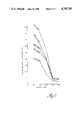
- the graph appearing in FIG. 1 of the accompanying drawingis an example of some of the test results that led to this finding.
- the chargewas progressively increased from a low or inefficient charge to the normal charge (0.75-2.75 lbs.) at progressively higher ambient air temperatures (60°-115° F.) and what are considered typical relative humidities for these temperatures (40-75%).
- the evaporator-out superheatincreases dramatically with decreased charge and increasing ambient temperature at the normally associated relative humidities. And thus a device which could sense and have an action response to both these conditions could perform the desired low charge detecting function.
- the low refrigerant charge detecting device of the present inventionhas this ability and comprises a refrigerant superheat temperature transducer, ambient air temperature transducer and a signal effecter.
- the superheat transducersenses the refrigerant leaving the evaporator and provides a positional output indicative of the superheat temperature thereof.
- the ambient transducersenses ambient air and provides a positional output indicative of the temperature thereof.
- the signal effecterresponds to both of the positional outputs and provides a low charge signal at a predetermined refrigerant superheat temperature and ambient air temperature.
- the superheat transducercomprises two bellows which are connected to move one of two movable contacts of an electrical switch forming the signal effecter.
- One of the bellowsis sealed with a certain amount of refrigerant therein and has a temperature probe exposed to the refrigerant leaving the evaporator such that this bellows becomes internally pressurized by the heat thereof in the superheat range.
- the other bellowsis exposed to the refrigerant leaving the evaporator and in response to the pressure thereof provides a balancing force against the sealed bellows at the saturated state.
- the other switch contactforms the ambient transducer and is preferably a bimetal disk or is mounted on a cantilevered bimetal element.
- the bimetal memberis exposed to the outside air and moves its contact relative to the other in response to ambient temperature change either in a single step manner or gradually in infinitesimal steps in the respective embodiments.
- the two bellows and bimetal membercooperate to control the relative positions of the electrical contacts such that they close to produce an alert signal or effect system shut down when a predetermined combination of evaporator-out superheat and ambient air temperature occurs indicating an undesirably low amount of refrigerant in the system.
- an object of the present inventionis to provide a new and improved low refrigerant charge detecting device.
- Another objectis to provide a low charge refrigerant detecting device that senses the superheat temperature of the refrigerant leaving the evaporator and ambient air temperature to indicate the amount of charge.
- Another objectis to provide a low charge refrigerant detecting device employing a refrigerant superheat transducer formed of a bellows arrangement, an ambient air temperature transducer formed of a bimetal member and a signal effecter formed by a switch having movable contacts operated by the respective transducers.
- FIG. 2is a schematic view of a motor vehicle air conditioning system that includes a top plan view of the accumulator/dehydrator with the low refrigerant charge detector according to the invention.
- FIG. 3is a sectional view of the detector in FIG. 2 taken along the line 3--3.
- FIG. 4is a view similar to FIG. 3 but showing another form of bimetal element in the ambient air transducer and signal effecter.
- the system shown in FIG. 2comprises a variable displacement refrigerant compressor 10 driven through an electromagnetic clutch 12 and belt 14 by the vehicle's engine (not shown).
- the compressordischarges hot vaporous refrigerant such as R12 to a condenser 16 for cooling resulting in liquefaction whereafter such is directed to an orifice tube expander 18.
- the latterreduces the pressure of the liquid refrigerant prior to passing on to an evaporator 20 where it absorbs heat from the ambient air thus cooling same.
- the liquid refrigerantvaporizes in the evaporator prior to passing on to an accumulator/dehydrator 22.
- a low (abnormal or ineffective) amount or charge of refrigerant in the systemis detected by a low refrigerant charge detecting device 24 located between the outlet of the evaporator and the suction side of the compressor and preferably fitted for convenience to the accumulator/dehydrator (also simply called the accumulator or receiver).
- the detecting devicecomprises a two piece casing 26 that is closed at one end 28 and has at the other end of a cylindrical wall section 30 an integral internally threaded fitting 32 by which the device is attached to an existing externally threaded system access fitting 34 on the side of the accumulator's housing 36.
- a sealed corrugated tubular bellows 40 formed of metal and charged with a certain amount of refrigerant and which will be referred to as a saturation pressure bellows because of its functionis located in the cylindrical wall section 30 of the casing and is retained at one closed end 42 thereof to the closed end 28 of the casing.
- Such end retentionis obtained by pressure forces from the bellows assembly exerted on this end of the casing, i.e. under all conditions, the free length of this assembly which includes a second bellows whose detailed description follows is greater than the internal distance of the casing where it captures this assembly endwise. While this form of end retention is preferred, it will also be understood that some other form of retention such as cement could be used where a rigid connection may be more feasible.
- the other closed end 44 of the sealed bellowsterminates approximately midway of the casing's cylindrical section where it is connected by soldering, brazing, welding or cementing to the closed end 46 of another corrugated tubular bellows 48 also of metal and together therewith by the same affixing means to an output arm 50.
- the arm 50extends laterally out into a side cavity 52 formed in the casing to support a superheat contact 54 having an electrical lead or wire 55 that extends out of the casing and connects with a signal or control circuit (not shown) as described in more detail later.
- the opposite end 56 of the latter bellows 48which will be referred to as an evaporator out or accumulator pressure bellows because of its function is open unlike the sealed bellows and sealingly connected about its end perimeter 60 by soldering, brazing, welding or cementing to the interior of the casing where the latter is open through its fitting 32 to the interior of the accumulator and thus to the refrigerant leaving the evaporator.
- the end 44 of the saturation pressure bellowsis formed with an integral tubular finger 64 that extends centrally therefrom and axially of this bellows and through the interior 66 of the evaporator out bellows 48 and terminates in the interior of fitting 32 to serve as a temperature sensing probe.
- a layer 68 of thermal insulationlines the interior of the casing at its closed end and cylindrical wall to shield both of the bellows from ambient air temperature with a slot 70 in the insulation layer allowing movement of the superheat output arm 50.
- a bimetal disk 72is located in the cavity 52 and fixed at its center on a pedestal 74 that is attached at its base to one side of this cavity.
- a contact 76 mounted on the perimeter of the disk 72is located opposite the superheat contact 54 and electrically connected by a lead 78 along with the superheat lead 55 to the previously mentioned circuit which is of an otherwise conventional for suitable to operating for example an alert signal or shutting the system off.
- Perforations 80 in the wall of the cavity 52provide for ambient air to the exterior of the bellows and to the disk 72 which is concave towards the superheat contact 54 at low ambient air temperatures and deflects to be concave away from this contact at high ambient air temperatures.
- the charge in the saturation pressure bellows 40is determined by conventional calculations and check by experimentation such that under all operating conditions there will exist a two phase (liquid and vapor) system therein at a given evaporator-out pressure and temperature sensed at the accumulator the evaporator out or accumulator bellows 48 will in response to the evaporator out pressure acting internally thereon exert a force against the saturation pressure bellows 40 proportional to the evaporator-out pressure.
- the saturation pressure bellowssenses the evaporator out temperature through its probe 64 and becomes internally pressurized to the saturation pressure corresponding to this temperature and as a result exerts a force against the evaporator-out pressure bellows proportional to the saturation pressure.
- the pressure on both bellowsis equal and neither is deflected in this equilibrium condition and the arm 50 is positioned as shown in solid line.
- the ambient air temperature sensing bimetal diskis calibrated to be concave toward the superheat contact as shown in phantom line when the ambient or outside air temperature is below a certain value so that a small value of superheat (e.g. 10° F.) will cause contact or switch closure when the outside temperature is low (e.g. 50° F.).
- a small value of superheate.g. 10° F.
- the bimetal diskwill deflect so as to concave away as shown in solid line so that a substantially larger amount of superheat (e.g. 50° F.) is needed to cause contact at higher ambient air temperatures.
- the signal effecteri.e. the switch
- the switchformed by the two independently positioned contacts 54 and 76 detect low refrigerant charge based on the relationship of evaporator discharge superheat as a function of ambient air temperature and charge as shown in FIG. 1.
- the ambient air switch portionmay take is shown in FIG. 4.
- the bimetal elementis in the form of a strip 80 that is bent in a U-shape, is fixed at one end to the casing, has the other end free and supporting the contact 76 and has its bimetal layers arranged so that the free end moves away from the superheat contact 54 at increasingly high outside air temperatures.
- the switchnow operates in infinitesimal steps rather than one distinct step in response to ambient air temperature change so as to provide a closer degree of detection.
Landscapes
- Engineering & Computer Science (AREA)
- Physics & Mathematics (AREA)
- Thermal Sciences (AREA)
- Mechanical Engineering (AREA)
- General Engineering & Computer Science (AREA)
- Thermally Actuated Switches (AREA)
Abstract
Description
This invention relates to low refrigerant charge detecting devices and more particularly to those for detecting low charge while the system is continuously running.
In motor vehicle air conditioning systems, there have been various approaches to detecting when the refrigerant becomes too low for continued system operation and either signaling an alert or shutting the system off. For example, one approach, for cycling clutcn systems only, has been to measure the temperature change in the refrigerant at the point of entering the evaporator for a brief time on start up. This is accomplished with a thermistor with a large change in temperature indicating a low charge. Another means of detecting low charge has been to employ a temperature switch that senses compressor discharge temperature and shuts the compressor off or signals an alert when the temperature exceeds a certain high or abnormal temperature. Another way of detecting a low charge has been to sense the liquid level of the refrigerant in the receiver or accumulator as the case may be. This is accomplished with a float switch that is operated by the refrigerant liquid level diminishing to a certain low or abnormal level.
Another method of low refrigerant charge detection has been to use a suction superheat switch which senses suction pressure and suction gas temperature and indicates low charge when the super heat of the suction gas of the compressor reaches a certain value. This superheat switch was not biased or compensated by ambient temperature. Another way of detecting low refrigerant charge has been to use a pressure switch which senses compressor discharge pressure. This switch indicates low charge when the pressure switch senses low discharge pressure.
The present invention utilizes the finding by the inventor that in motor vehicle air conditioning systems that run continuously such as with a variable displacement compressor, the superheat temperature (degrees Fahrenheit above the saturation or boiling temperature) of the refrigerant exiting the evaporator is largely a function of charge (amount of refrigerant in the system) and ambient air temperature. The graph appearing in FIG. 1 of the accompanying drawing is an example of some of the test results that led to this finding. In these tests, the charge was progressively increased from a low or inefficient charge to the normal charge (0.75-2.75 lbs.) at progressively higher ambient air temperatures (60°-115° F.) and what are considered typical relative humidities for these temperatures (40-75%). As can be seen, the evaporator-out superheat increases dramatically with decreased charge and increasing ambient temperature at the normally associated relative humidities. And thus a device which could sense and have an action response to both these conditions could perform the desired low charge detecting function.
The low refrigerant charge detecting device of the present invention has this ability and comprises a refrigerant superheat temperature transducer, ambient air temperature transducer and a signal effecter. The superheat transducer senses the refrigerant leaving the evaporator and provides a positional output indicative of the superheat temperature thereof. The ambient transducer senses ambient air and provides a positional output indicative of the temperature thereof. And the signal effecter responds to both of the positional outputs and provides a low charge signal at a predetermined refrigerant superheat temperature and ambient air temperature. Preferably, the superheat transducer comprises two bellows which are connected to move one of two movable contacts of an electrical switch forming the signal effecter. One of the bellows is sealed with a certain amount of refrigerant therein and has a temperature probe exposed to the refrigerant leaving the evaporator such that this bellows becomes internally pressurized by the heat thereof in the superheat range. The other bellows is exposed to the refrigerant leaving the evaporator and in response to the pressure thereof provides a balancing force against the sealed bellows at the saturated state. The other switch contact forms the ambient transducer and is preferably a bimetal disk or is mounted on a cantilevered bimetal element. The bimetal member is exposed to the outside air and moves its contact relative to the other in response to ambient temperature change either in a single step manner or gradually in infinitesimal steps in the respective embodiments. The two bellows and bimetal member cooperate to control the relative positions of the electrical contacts such that they close to produce an alert signal or effect system shut down when a predetermined combination of evaporator-out superheat and ambient air temperature occurs indicating an undesirably low amount of refrigerant in the system.
With the above in mind, an object of the present invention is to provide a new and improved low refrigerant charge detecting device.
Another object is to provide a low charge refrigerant detecting device that senses the superheat temperature of the refrigerant leaving the evaporator and ambient air temperature to indicate the amount of charge.
Another object is to provide a low charge refrigerant detecting device employing a refrigerant superheat transducer formed of a bellows arrangement, an ambient air temperature transducer formed of a bimetal member and a signal effecter formed by a switch having movable contacts operated by the respective transducers.
These and other objects, advantages and features of the invention will become more apparent from the following description and drawing in which in addition to FIG. 1; previously discussed:
FIG. 2 is a schematic view of a motor vehicle air conditioning system that includes a top plan view of the accumulator/dehydrator with the low refrigerant charge detector according to the invention.
FIG. 3 is a sectional view of the detector in FIG. 2 taken along theline 3--3.
FIG. 4 is a view similar to FIG. 3 but showing another form of bimetal element in the ambient air transducer and signal effecter.
Referring to the drawing wherein the same numbers are used to identify the same parts throughout the several views, the system shown in FIG. 2 comprises a variabledisplacement refrigerant compressor 10 driven through anelectromagnetic clutch 12 and belt 14 by the vehicle's engine (not shown). The compressor discharges hot vaporous refrigerant such as R12 to acondenser 16 for cooling resulting in liquefaction whereafter such is directed to anorifice tube expander 18. The latter reduces the pressure of the liquid refrigerant prior to passing on to anevaporator 20 where it absorbs heat from the ambient air thus cooling same. By absorbing heat from the air the liquid refrigerant vaporizes in the evaporator prior to passing on to an accumulator/dehydrator 22. At the latter, any water is collected and retained by a desiccant and any remaining liquid refrigerant is separated out and eventually returned in vapor form along with the other vaporous refrigerant to the suction side of the compressor to complete the cycle. The system thus far described is conventional with tne displacement of the compressor being varied in accordance with the cooling demand rather than cycling the clutch off and on as would be the case with a fixed displacement compressor.
A low (abnormal or ineffective) amount or charge of refrigerant in the system is detected by a low refrigerantcharge detecting device 24 located between the outlet of the evaporator and the suction side of the compressor and preferably fitted for convenience to the accumulator/dehydrator (also simply called the accumulator or receiver). Referring to FIGS. 2 and 3, the detecting device comprises a twopiece casing 26 that is closed at oneend 28 and has at the other end of acylindrical wall section 30 an integral internally threadedfitting 32 by which the device is attached to an existing externally threaded system access fitting 34 on the side of the accumulator'shousing 36. A sealed corrugatedtubular bellows 40 formed of metal and charged with a certain amount of refrigerant and which will be referred to as a saturation pressure bellows because of its function is located in thecylindrical wall section 30 of the casing and is retained at one closedend 42 thereof to the closedend 28 of the casing. Such end retention is obtained by pressure forces from the bellows assembly exerted on this end of the casing, i.e. under all conditions, the free length of this assembly which includes a second bellows whose detailed description follows is greater than the internal distance of the casing where it captures this assembly endwise. While this form of end retention is preferred, it will also be understood that some other form of retention such as cement could be used where a rigid connection may be more feasible. The other closedend 44 of the sealed bellows terminates approximately midway of the casing's cylindrical section where it is connected by soldering, brazing, welding or cementing to the closedend 46 of another corrugatedtubular bellows 48 also of metal and together therewith by the same affixing means to anoutput arm 50. Thearm 50 extends laterally out into aside cavity 52 formed in the casing to support asuperheat contact 54 having an electrical lead orwire 55 that extends out of the casing and connects with a signal or control circuit (not shown) as described in more detail later.
Theopposite end 56 of thelatter bellows 48 which will be referred to as an evaporator out or accumulator pressure bellows because of its function is open unlike the sealed bellows and sealingly connected about itsend perimeter 60 by soldering, brazing, welding or cementing to the interior of the casing where the latter is open through itsfitting 32 to the interior of the accumulator and thus to the refrigerant leaving the evaporator. Theend 44 of the saturation pressure bellows is formed with an integraltubular finger 64 that extends centrally therefrom and axially of this bellows and through theinterior 66 of the evaporator outbellows 48 and terminates in the interior of fitting 32 to serve as a temperature sensing probe. Alayer 68 of thermal insulation lines the interior of the casing at its closed end and cylindrical wall to shield both of the bellows from ambient air temperature with aslot 70 in the insulation layer allowing movement of thesuperheat output arm 50.
Abimetal disk 72 is located in thecavity 52 and fixed at its center on apedestal 74 that is attached at its base to one side of this cavity. Acontact 76 mounted on the perimeter of thedisk 72 is located opposite thesuperheat contact 54 and electrically connected by alead 78 along with thesuperheat lead 55 to the previously mentioned circuit which is of an otherwise conventional for suitable to operating for example an alert signal or shutting the system off.Perforations 80 in the wall of thecavity 52 provide for ambient air to the exterior of the bellows and to thedisk 72 which is concave towards thesuperheat contact 54 at low ambient air temperatures and deflects to be concave away from this contact at high ambient air temperatures.
Describing now the calibration and operation of the detecting device, the charge in thesaturation pressure bellows 40 is determined by conventional calculations and check by experimentation such that under all operating conditions there will exist a two phase (liquid and vapor) system therein at a given evaporator-out pressure and temperature sensed at the accumulator the evaporator out oraccumulator bellows 48 will in response to the evaporator out pressure acting internally thereon exert a force against thesaturation pressure bellows 40 proportional to the evaporator-out pressure. The saturation pressure bellows senses the evaporator out temperature through itsprobe 64 and becomes internally pressurized to the saturation pressure corresponding to this temperature and as a result exerts a force against the evaporator-out pressure bellows proportional to the saturation pressure. When the refrigerant out of the evaporator is at the saturated state (zero degrees superheat) the pressure on both bellows is equal and neither is deflected in this equilibrium condition and thearm 50 is positioned as shown in solid line. Then should the refrigerant out of the evaporator become superheated, the pressure in the saturated pressure bellows will become greater than the pressure of this refrigerant causing the former bellows to extend while the latter bellows contracts until static equilibrium is reached and whereupon thesuperheat contact 54 is moved by thearm 50 and positioned closer to theambient air contact 76 as shown in phantom line. Alternatively, when the superheat decreases the reverse occurs moving the superheat contact further from the ambient air contact.
The ambient air temperature sensing bimetal disk is calibrated to be concave toward the superheat contact as shown in phantom line when the ambient or outside air temperature is below a certain value so that a small value of superheat (e.g. 10° F.) will cause contact or switch closure when the outside temperature is low (e.g. 50° F.). Alternatively, when the outside temperature is high (e.g. 100° F.) the bimetal disk will deflect so as to concave away as shown in solid line so that a substantially larger amount of superheat (e.g. 50° F.) is needed to cause contact at higher ambient air temperatures. Thus the signal effecter (i.e. the switch) formed by the two independently positionedcontacts
Another form that the ambient air switch portion may take is shown in FIG. 4. In this version, the bimetal element is in the form of astrip 80 that is bent in a U-shape, is fixed at one end to the casing, has the other end free and supporting thecontact 76 and has its bimetal layers arranged so that the free end moves away from thesuperheat contact 54 at increasingly high outside air temperatures. As a result, the switch now operates in infinitesimal steps rather than one distinct step in response to ambient air temperature change so as to provide a closer degree of detection.
The above described preferred embodiments are illustrative of the invention which may be modified within the scope of the appended claim.
Claims (1)
1. In an air conditioning system charged with a refrigerant whose amount may diminish in time, said system including a evaporator, an improved low refrigerant charge detecting device comprising a sealed bellows containing refrigerant having a stationary end and an extendible end, said extendible end supporting an electrical contact and formed with a protruding temperature probe portion exposed to the refrigerant leaving the evaporator, an open bellows having a stationary end open to the refrigerant leaving the evaporator and an extendible end fixed to the extendible end of said sealed bellows about said probe portion, and a bimetal element exposed to ambient air supporting an electrical contact located opposite said first mentioned contact.
Priority Applications (1)
| Application Number | Priority Date | Filing Date | Title |
|---|---|---|---|
| US07/048,371US4745765A (en) | 1987-05-11 | 1987-05-11 | Low refrigerant charge detecting device |
Applications Claiming Priority (1)
| Application Number | Priority Date | Filing Date | Title |
|---|---|---|---|
| US07/048,371US4745765A (en) | 1987-05-11 | 1987-05-11 | Low refrigerant charge detecting device |
Publications (1)
| Publication Number | Publication Date |
|---|---|
| US4745765Atrue US4745765A (en) | 1988-05-24 |
Family
ID=21954213
Family Applications (1)
| Application Number | Title | Priority Date | Filing Date |
|---|---|---|---|
| US07/048,371Expired - Fee RelatedUS4745765A (en) | 1987-05-11 | 1987-05-11 | Low refrigerant charge detecting device |
Country Status (1)
| Country | Link |
|---|---|
| US (1) | US4745765A (en) |
Cited By (46)
| Publication number | Priority date | Publication date | Assignee | Title |
|---|---|---|---|---|
| US5009076A (en)* | 1990-03-08 | 1991-04-23 | Temperature Engineering Corp. | Refrigerant loss monitor |
| US5079930A (en)* | 1990-12-03 | 1992-01-14 | Atron, Inc. | Apparatus and method for monitoring refrigeration system |
| US5186014A (en)* | 1992-07-13 | 1993-02-16 | General Motors Corporation | Low refrigerant charge detection system for a heat pump |
| US5216894A (en)* | 1991-10-18 | 1993-06-08 | Samsung Electronics Co., Ltd. | Control switch |
| US5228304A (en)* | 1992-06-04 | 1993-07-20 | Ryan David J | Refrigerant loss detector and alarm |
| US5243829A (en)* | 1992-10-21 | 1993-09-14 | General Electric Company | Low refrigerant charge detection using thermal expansion valve stroke measurement |
| US5285648A (en)* | 1992-10-21 | 1994-02-15 | General Electric Company | Differential pressure superheat sensor for low refrigerant charge detection |
| US5301514A (en)* | 1992-12-02 | 1994-04-12 | General Electric Company | Low refrigerant charge detection by monitoring thermal expansion valve oscillation |
| US5381669A (en)* | 1993-07-21 | 1995-01-17 | Copeland Corporation | Overcharge-undercharge diagnostic system for air conditioner controller |
| US5457965A (en)* | 1994-04-11 | 1995-10-17 | Ford Motor Company | Low refrigerant charge detection system |
| US5481884A (en)* | 1994-08-29 | 1996-01-09 | General Motors Corporation | Apparatus and method for providing low refrigerant charge detection |
| US5560213A (en)* | 1994-01-19 | 1996-10-01 | Mercedes-Benz Ag | Process for monitoring the refrigerant fill-level in a refrigeration system |
| US5623834A (en)* | 1995-05-03 | 1997-04-29 | Copeland Corporation | Diagnostics for a heating and cooling system |
| US5628201A (en)* | 1995-04-03 | 1997-05-13 | Copeland Corporation | Heating and cooling system with variable capacity compressor |
| FR2774155A1 (en)* | 1998-01-29 | 1999-07-30 | Valeo Climatisation | System for evaluating the under cooling state of refrigerating liquid in vehicle air conditioning system |
| FR2797038A1 (en)* | 1999-07-27 | 2001-02-02 | Daimler Chrysler Ag | METHOD FOR MONITORING THE REFRIGERATION FLUID FILLING LEVEL IN A REFRIGERATION INSTALLATION |
| US6330802B1 (en) | 2000-02-22 | 2001-12-18 | Behr Climate Systems, Inc. | Refrigerant loss detection |
| EP1213549A1 (en) | 2000-12-11 | 2002-06-12 | Behr GmbH & Co. | Method for monitoring the refrigerant charge |
| US6571566B1 (en) | 2002-04-02 | 2003-06-03 | Lennox Manufacturing Inc. | Method of determining refrigerant charge level in a space temperature conditioning system |
| US20050126190A1 (en)* | 2003-12-10 | 2005-06-16 | Alexander Lifson | Loss of refrigerant charge and expansion valve malfunction detection |
| US20070150305A1 (en)* | 2004-02-18 | 2007-06-28 | Klaus Abraham-Fuchs | Method for selecting a potential participant for a medical study on the basis of a selection criterion |
| US20070256434A1 (en)* | 2006-05-04 | 2007-11-08 | Kwangtaek Hong | Monitoring System for Detecting Low-Charge Condition in a Heat-Exchange System |
| US20080209925A1 (en)* | 2006-07-19 | 2008-09-04 | Pham Hung M | Protection and diagnostic module for a refrigeration system |
| US20100111709A1 (en)* | 2003-12-30 | 2010-05-06 | Emerson Climate Technologies, Inc. | Compressor protection and diagnostic system |
| US7878006B2 (en) | 2004-04-27 | 2011-02-01 | Emerson Climate Technologies, Inc. | Compressor diagnostic and protection system and method |
| US20110222576A1 (en)* | 2008-09-05 | 2011-09-15 | Danfoss A/S | Method for calibrating a superheat sensor |
| US8160827B2 (en) | 2007-11-02 | 2012-04-17 | Emerson Climate Technologies, Inc. | Compressor sensor module |
| JP2012193875A (en)* | 2011-03-15 | 2012-10-11 | Hoshizaki Electric Co Ltd | Singurasu ice maker |
| US8393169B2 (en) | 2007-09-19 | 2013-03-12 | Emerson Climate Technologies, Inc. | Refrigeration monitoring system and method |
| US8964338B2 (en) | 2012-01-11 | 2015-02-24 | Emerson Climate Technologies, Inc. | System and method for compressor motor protection |
| US8974573B2 (en) | 2004-08-11 | 2015-03-10 | Emerson Climate Technologies, Inc. | Method and apparatus for monitoring a refrigeration-cycle system |
| US9140728B2 (en) | 2007-11-02 | 2015-09-22 | Emerson Climate Technologies, Inc. | Compressor sensor module |
| US9285802B2 (en) | 2011-02-28 | 2016-03-15 | Emerson Electric Co. | Residential solutions HVAC monitoring and diagnosis |
| US20160091241A1 (en)* | 2013-08-26 | 2016-03-31 | Mitsubishi Electric Corporation | Air-conditioning apparatus and refrigerant leakage detection method |
| US9310094B2 (en) | 2007-07-30 | 2016-04-12 | Emerson Climate Technologies, Inc. | Portable method and apparatus for monitoring refrigerant-cycle systems |
| US9310439B2 (en) | 2012-09-25 | 2016-04-12 | Emerson Climate Technologies, Inc. | Compressor having a control and diagnostic module |
| US9480177B2 (en) | 2012-07-27 | 2016-10-25 | Emerson Climate Technologies, Inc. | Compressor protection module |
| US9551504B2 (en) | 2013-03-15 | 2017-01-24 | Emerson Electric Co. | HVAC system remote monitoring and diagnosis |
| US9638436B2 (en) | 2013-03-15 | 2017-05-02 | Emerson Electric Co. | HVAC system remote monitoring and diagnosis |
| US9765979B2 (en) | 2013-04-05 | 2017-09-19 | Emerson Climate Technologies, Inc. | Heat-pump system with refrigerant charge diagnostics |
| US9823632B2 (en) | 2006-09-07 | 2017-11-21 | Emerson Climate Technologies, Inc. | Compressor data module |
| EP3255360B1 (en) | 2016-06-08 | 2018-11-14 | Truma Gerätetechnik GmbH & Co. KG | Air conditioning system and method for leakage detection in an air conditioning system |
| EP3415840A2 (en) | 2017-05-23 | 2018-12-19 | SmartGreen Ltd. | Detection of lack of refrigerant in a cooling system having multiple cooling locations |
| US10488090B2 (en) | 2013-03-15 | 2019-11-26 | Emerson Climate Technologies, Inc. | System for refrigerant charge verification |
| WO2022207166A1 (en)* | 2021-03-31 | 2022-10-06 | Audi Ag | Method for monitoring a refrigerant fill-quantity in a refrigeration machine, refrigeration machine, and motor vehicle |
| DE102022113830A1 (en) | 2022-06-01 | 2023-12-07 | Audi Aktiengesellschaft | Method for determining a quantity of refrigerant in a refrigerant circuit of a motor vehicle and motor vehicle |
Citations (6)
| Publication number | Priority date | Publication date | Assignee | Title |
|---|---|---|---|---|
| US2621487A (en)* | 1951-12-12 | 1952-12-16 | George H Warren | Safety control means for refrigerating systems |
| US3047696A (en)* | 1959-12-11 | 1962-07-31 | Gen Motors Corp | Superheat control |
| US3303663A (en)* | 1965-10-20 | 1967-02-14 | Luxaire Inc | Refrigeration system charging apparatus |
| US3400552A (en)* | 1967-02-13 | 1968-09-10 | Luxaire Inc | Electrically controlled refrigerant charging device |
| US3729949A (en)* | 1971-12-06 | 1973-05-01 | J Talbot | Refrigerant charging control unit |
| US4106306A (en)* | 1976-06-24 | 1978-08-15 | The Trane Company | Refrigerant charge adjuster apparatus |
- 1987
- 1987-05-11USUS07/048,371patent/US4745765A/ennot_activeExpired - Fee Related
Patent Citations (6)
| Publication number | Priority date | Publication date | Assignee | Title |
|---|---|---|---|---|
| US2621487A (en)* | 1951-12-12 | 1952-12-16 | George H Warren | Safety control means for refrigerating systems |
| US3047696A (en)* | 1959-12-11 | 1962-07-31 | Gen Motors Corp | Superheat control |
| US3303663A (en)* | 1965-10-20 | 1967-02-14 | Luxaire Inc | Refrigeration system charging apparatus |
| US3400552A (en)* | 1967-02-13 | 1968-09-10 | Luxaire Inc | Electrically controlled refrigerant charging device |
| US3729949A (en)* | 1971-12-06 | 1973-05-01 | J Talbot | Refrigerant charging control unit |
| US4106306A (en)* | 1976-06-24 | 1978-08-15 | The Trane Company | Refrigerant charge adjuster apparatus |
Cited By (89)
| Publication number | Priority date | Publication date | Assignee | Title |
|---|---|---|---|---|
| US5009076A (en)* | 1990-03-08 | 1991-04-23 | Temperature Engineering Corp. | Refrigerant loss monitor |
| US5079930A (en)* | 1990-12-03 | 1992-01-14 | Atron, Inc. | Apparatus and method for monitoring refrigeration system |
| US5216894A (en)* | 1991-10-18 | 1993-06-08 | Samsung Electronics Co., Ltd. | Control switch |
| US5228304A (en)* | 1992-06-04 | 1993-07-20 | Ryan David J | Refrigerant loss detector and alarm |
| US5186014A (en)* | 1992-07-13 | 1993-02-16 | General Motors Corporation | Low refrigerant charge detection system for a heat pump |
| US5243829A (en)* | 1992-10-21 | 1993-09-14 | General Electric Company | Low refrigerant charge detection using thermal expansion valve stroke measurement |
| US5285648A (en)* | 1992-10-21 | 1994-02-15 | General Electric Company | Differential pressure superheat sensor for low refrigerant charge detection |
| US5301514A (en)* | 1992-12-02 | 1994-04-12 | General Electric Company | Low refrigerant charge detection by monitoring thermal expansion valve oscillation |
| US5381669A (en)* | 1993-07-21 | 1995-01-17 | Copeland Corporation | Overcharge-undercharge diagnostic system for air conditioner controller |
| US5560213A (en)* | 1994-01-19 | 1996-10-01 | Mercedes-Benz Ag | Process for monitoring the refrigerant fill-level in a refrigeration system |
| US5457965A (en)* | 1994-04-11 | 1995-10-17 | Ford Motor Company | Low refrigerant charge detection system |
| US5481884A (en)* | 1994-08-29 | 1996-01-09 | General Motors Corporation | Apparatus and method for providing low refrigerant charge detection |
| US5628201A (en)* | 1995-04-03 | 1997-05-13 | Copeland Corporation | Heating and cooling system with variable capacity compressor |
| US5623834A (en)* | 1995-05-03 | 1997-04-29 | Copeland Corporation | Diagnostics for a heating and cooling system |
| US5689963A (en)* | 1995-05-03 | 1997-11-25 | Copeland Corporation | Diagnostics for a heating and cooling system |
| FR2774155A1 (en)* | 1998-01-29 | 1999-07-30 | Valeo Climatisation | System for evaluating the under cooling state of refrigerating liquid in vehicle air conditioning system |
| FR2797038A1 (en)* | 1999-07-27 | 2001-02-02 | Daimler Chrysler Ag | METHOD FOR MONITORING THE REFRIGERATION FLUID FILLING LEVEL IN A REFRIGERATION INSTALLATION |
| US6446505B1 (en) | 1999-07-27 | 2002-09-10 | Daimlerchrysler Ag | Method for monitoring the refrigerant filling level in refrigerating system |
| US6330802B1 (en) | 2000-02-22 | 2001-12-18 | Behr Climate Systems, Inc. | Refrigerant loss detection |
| EP1213549A1 (en) | 2000-12-11 | 2002-06-12 | Behr GmbH & Co. | Method for monitoring the refrigerant charge |
| US6708508B2 (en) | 2000-12-11 | 2004-03-23 | Behr Gmbh & Co. | Method of monitoring refrigerant level |
| US20040159114A1 (en)* | 2000-12-11 | 2004-08-19 | Behr Gmbh & Co. | Method of monitoring refrigerant level |
| US7146819B2 (en) | 2000-12-11 | 2006-12-12 | Behr Gmbh & Co. | Method of monitoring refrigerant level |
| DE10061545A1 (en)* | 2000-12-11 | 2002-06-13 | Behr Gmbh & Co | Procedure for refrigerant level monitoring |
| US6571566B1 (en) | 2002-04-02 | 2003-06-03 | Lennox Manufacturing Inc. | Method of determining refrigerant charge level in a space temperature conditioning system |
| US20050126190A1 (en)* | 2003-12-10 | 2005-06-16 | Alexander Lifson | Loss of refrigerant charge and expansion valve malfunction detection |
| US20100111709A1 (en)* | 2003-12-30 | 2010-05-06 | Emerson Climate Technologies, Inc. | Compressor protection and diagnostic system |
| US8475136B2 (en) | 2003-12-30 | 2013-07-02 | Emerson Climate Technologies, Inc. | Compressor protection and diagnostic system |
| US20070150305A1 (en)* | 2004-02-18 | 2007-06-28 | Klaus Abraham-Fuchs | Method for selecting a potential participant for a medical study on the basis of a selection criterion |
| US20170266769A1 (en)* | 2004-04-27 | 2017-09-21 | Emerson Climate Technologies, Inc. | Compressor diagnostic and protection system and method |
| US7878006B2 (en) | 2004-04-27 | 2011-02-01 | Emerson Climate Technologies, Inc. | Compressor diagnostic and protection system and method |
| US7905098B2 (en) | 2004-04-27 | 2011-03-15 | Emerson Climate Technologies, Inc. | Compressor diagnostic and protection system and method |
| US9669498B2 (en) | 2004-04-27 | 2017-06-06 | Emerson Climate Technologies, Inc. | Compressor diagnostic and protection system and method |
| US9121407B2 (en) | 2004-04-27 | 2015-09-01 | Emerson Climate Technologies, Inc. | Compressor diagnostic and protection system and method |
| US8474278B2 (en) | 2004-04-27 | 2013-07-02 | Emerson Climate Technologies, Inc. | Compressor diagnostic and protection system and method |
| US10335906B2 (en)* | 2004-04-27 | 2019-07-02 | Emerson Climate Technologies, Inc. | Compressor diagnostic and protection system and method |
| US9023136B2 (en) | 2004-08-11 | 2015-05-05 | Emerson Climate Technologies, Inc. | Method and apparatus for monitoring a refrigeration-cycle system |
| US9081394B2 (en) | 2004-08-11 | 2015-07-14 | Emerson Climate Technologies, Inc. | Method and apparatus for monitoring a refrigeration-cycle system |
| US9690307B2 (en) | 2004-08-11 | 2017-06-27 | Emerson Climate Technologies, Inc. | Method and apparatus for monitoring refrigeration-cycle systems |
| US9304521B2 (en) | 2004-08-11 | 2016-04-05 | Emerson Climate Technologies, Inc. | Air filter monitoring system |
| US10558229B2 (en) | 2004-08-11 | 2020-02-11 | Emerson Climate Technologies Inc. | Method and apparatus for monitoring refrigeration-cycle systems |
| US9086704B2 (en) | 2004-08-11 | 2015-07-21 | Emerson Climate Technologies, Inc. | Method and apparatus for monitoring a refrigeration-cycle system |
| US8974573B2 (en) | 2004-08-11 | 2015-03-10 | Emerson Climate Technologies, Inc. | Method and apparatus for monitoring a refrigeration-cycle system |
| US9017461B2 (en) | 2004-08-11 | 2015-04-28 | Emerson Climate Technologies, Inc. | Method and apparatus for monitoring a refrigeration-cycle system |
| US9046900B2 (en) | 2004-08-11 | 2015-06-02 | Emerson Climate Technologies, Inc. | Method and apparatus for monitoring refrigeration-cycle systems |
| US9021819B2 (en) | 2004-08-11 | 2015-05-05 | Emerson Climate Technologies, Inc. | Method and apparatus for monitoring a refrigeration-cycle system |
| US20070256434A1 (en)* | 2006-05-04 | 2007-11-08 | Kwangtaek Hong | Monitoring System for Detecting Low-Charge Condition in a Heat-Exchange System |
| US20080209925A1 (en)* | 2006-07-19 | 2008-09-04 | Pham Hung M | Protection and diagnostic module for a refrigeration system |
| US8590325B2 (en) | 2006-07-19 | 2013-11-26 | Emerson Climate Technologies, Inc. | Protection and diagnostic module for a refrigeration system |
| US9885507B2 (en) | 2006-07-19 | 2018-02-06 | Emerson Climate Technologies, Inc. | Protection and diagnostic module for a refrigeration system |
| US9823632B2 (en) | 2006-09-07 | 2017-11-21 | Emerson Climate Technologies, Inc. | Compressor data module |
| US9310094B2 (en) | 2007-07-30 | 2016-04-12 | Emerson Climate Technologies, Inc. | Portable method and apparatus for monitoring refrigerant-cycle systems |
| US10352602B2 (en) | 2007-07-30 | 2019-07-16 | Emerson Climate Technologies, Inc. | Portable method and apparatus for monitoring refrigerant-cycle systems |
| US9651286B2 (en) | 2007-09-19 | 2017-05-16 | Emerson Climate Technologies, Inc. | Refrigeration monitoring system and method |
| US8393169B2 (en) | 2007-09-19 | 2013-03-12 | Emerson Climate Technologies, Inc. | Refrigeration monitoring system and method |
| US9194894B2 (en) | 2007-11-02 | 2015-11-24 | Emerson Climate Technologies, Inc. | Compressor sensor module |
| US9140728B2 (en) | 2007-11-02 | 2015-09-22 | Emerson Climate Technologies, Inc. | Compressor sensor module |
| US8160827B2 (en) | 2007-11-02 | 2012-04-17 | Emerson Climate Technologies, Inc. | Compressor sensor module |
| US10458404B2 (en) | 2007-11-02 | 2019-10-29 | Emerson Climate Technologies, Inc. | Compressor sensor module |
| US8335657B2 (en) | 2007-11-02 | 2012-12-18 | Emerson Climate Technologies, Inc. | Compressor sensor module |
| US20110222576A1 (en)* | 2008-09-05 | 2011-09-15 | Danfoss A/S | Method for calibrating a superheat sensor |
| US8827546B2 (en)* | 2008-09-05 | 2014-09-09 | Danfoss A/S | Method for calibrating a superheat sensor |
| US10234854B2 (en) | 2011-02-28 | 2019-03-19 | Emerson Electric Co. | Remote HVAC monitoring and diagnosis |
| US10884403B2 (en) | 2011-02-28 | 2021-01-05 | Emerson Electric Co. | Remote HVAC monitoring and diagnosis |
| US9703287B2 (en) | 2011-02-28 | 2017-07-11 | Emerson Electric Co. | Remote HVAC monitoring and diagnosis |
| US9285802B2 (en) | 2011-02-28 | 2016-03-15 | Emerson Electric Co. | Residential solutions HVAC monitoring and diagnosis |
| JP2012193875A (en)* | 2011-03-15 | 2012-10-11 | Hoshizaki Electric Co Ltd | Singurasu ice maker |
| US9590413B2 (en) | 2012-01-11 | 2017-03-07 | Emerson Climate Technologies, Inc. | System and method for compressor motor protection |
| US8964338B2 (en) | 2012-01-11 | 2015-02-24 | Emerson Climate Technologies, Inc. | System and method for compressor motor protection |
| US9876346B2 (en) | 2012-01-11 | 2018-01-23 | Emerson Climate Technologies, Inc. | System and method for compressor motor protection |
| US10485128B2 (en) | 2012-07-27 | 2019-11-19 | Emerson Climate Technologies, Inc. | Compressor protection module |
| US9480177B2 (en) | 2012-07-27 | 2016-10-25 | Emerson Climate Technologies, Inc. | Compressor protection module |
| US10028399B2 (en) | 2012-07-27 | 2018-07-17 | Emerson Climate Technologies, Inc. | Compressor protection module |
| US9310439B2 (en) | 2012-09-25 | 2016-04-12 | Emerson Climate Technologies, Inc. | Compressor having a control and diagnostic module |
| US9762168B2 (en) | 2012-09-25 | 2017-09-12 | Emerson Climate Technologies, Inc. | Compressor having a control and diagnostic module |
| US9638436B2 (en) | 2013-03-15 | 2017-05-02 | Emerson Electric Co. | HVAC system remote monitoring and diagnosis |
| US9551504B2 (en) | 2013-03-15 | 2017-01-24 | Emerson Electric Co. | HVAC system remote monitoring and diagnosis |
| US10274945B2 (en) | 2013-03-15 | 2019-04-30 | Emerson Electric Co. | HVAC system remote monitoring and diagnosis |
| US10775084B2 (en) | 2013-03-15 | 2020-09-15 | Emerson Climate Technologies, Inc. | System for refrigerant charge verification |
| US10488090B2 (en) | 2013-03-15 | 2019-11-26 | Emerson Climate Technologies, Inc. | System for refrigerant charge verification |
| US10060636B2 (en) | 2013-04-05 | 2018-08-28 | Emerson Climate Technologies, Inc. | Heat pump system with refrigerant charge diagnostics |
| US9765979B2 (en) | 2013-04-05 | 2017-09-19 | Emerson Climate Technologies, Inc. | Heat-pump system with refrigerant charge diagnostics |
| US10443863B2 (en) | 2013-04-05 | 2019-10-15 | Emerson Climate Technologies, Inc. | Method of monitoring charge condition of heat pump system |
| US10539358B2 (en)* | 2013-08-26 | 2020-01-21 | Mitsubishi Electric Corporation | Air-conditioning apparatus and refrigerant leakage detection method |
| US20160091241A1 (en)* | 2013-08-26 | 2016-03-31 | Mitsubishi Electric Corporation | Air-conditioning apparatus and refrigerant leakage detection method |
| EP3255360B1 (en) | 2016-06-08 | 2018-11-14 | Truma Gerätetechnik GmbH & Co. KG | Air conditioning system and method for leakage detection in an air conditioning system |
| EP3415840A2 (en) | 2017-05-23 | 2018-12-19 | SmartGreen Ltd. | Detection of lack of refrigerant in a cooling system having multiple cooling locations |
| WO2022207166A1 (en)* | 2021-03-31 | 2022-10-06 | Audi Ag | Method for monitoring a refrigerant fill-quantity in a refrigeration machine, refrigeration machine, and motor vehicle |
| DE102022113830A1 (en) | 2022-06-01 | 2023-12-07 | Audi Aktiengesellschaft | Method for determining a quantity of refrigerant in a refrigerant circuit of a motor vehicle and motor vehicle |
Similar Documents
| Publication | Publication Date | Title |
|---|---|---|
| US4745765A (en) | Low refrigerant charge detecting device | |
| US5243829A (en) | Low refrigerant charge detection using thermal expansion valve stroke measurement | |
| US5228304A (en) | Refrigerant loss detector and alarm | |
| US4167858A (en) | Refrigerant deficiency detecting apparatus | |
| US5301514A (en) | Low refrigerant charge detection by monitoring thermal expansion valve oscillation | |
| US4878355A (en) | Method and apparatus for improving cooling of a compressor element in an air conditioning system | |
| US5079930A (en) | Apparatus and method for monitoring refrigeration system | |
| US7631508B2 (en) | Apparatus and method for determining refrigerant charge level | |
| US4848100A (en) | Controlling refrigeration | |
| US5586445A (en) | Low refrigerant charge detection using a combined pressure/temperature sensor | |
| US5457965A (en) | Low refrigerant charge detection system | |
| US5044168A (en) | Apparatus and method for low refrigerant detection | |
| US5778695A (en) | Liquid level sensor using refrigrant subcooling | |
| US3913347A (en) | Superheat control system | |
| US4614087A (en) | Apparatus for alarming abnormal coolant in space cooling cycle | |
| US4545212A (en) | Super-heat detector for refrigerating apparatus | |
| US5285648A (en) | Differential pressure superheat sensor for low refrigerant charge detection | |
| CA1233212A (en) | Measuring device for detecting a liquid component in refrigerant | |
| EP0680590B1 (en) | Conditioning sensing system for controlling working fluids | |
| US5691466A (en) | Liquid-sensing apparatus and method | |
| EP0276491A2 (en) | Control system for air cooling | |
| KR960002567B1 (en) | Refrigeration circuit | |
| JPH06117736A (en) | Detecting device for sealed refrigerant quantity | |
| JPS587318Y2 (en) | pressure sensing device | |
| JPS602578B2 (en) | Refrigeration equipment |
Legal Events
| Date | Code | Title | Description |
|---|---|---|---|
| AS | Assignment | Owner name:GENERAL MOTORS CORPORATION, DETROIT, MICHIGAN A CO Free format text:ASSIGNMENT OF ASSIGNORS INTEREST.;ASSIGNOR:PETTITT, EDWARD D.;REEL/FRAME:004713/0425 Effective date:19870504 Owner name:GENERAL MOTORS CORPORATION, A CORP. OF DE.,MICHIGA Free format text:ASSIGNMENT OF ASSIGNORS INTEREST;ASSIGNOR:PETTITT, EDWARD D.;REEL/FRAME:004713/0425 Effective date:19870504 | |
| REMI | Maintenance fee reminder mailed | ||
| REMI | Maintenance fee reminder mailed | ||
| LAPS | Lapse for failure to pay maintenance fees | ||
| FP | Lapsed due to failure to pay maintenance fee | Effective date:19920524 | |
| STCH | Information on status: patent discontinuation | Free format text:PATENT EXPIRED DUE TO NONPAYMENT OF MAINTENANCE FEES UNDER 37 CFR 1.362 |