US4745408A - Radio paging system and receiver therefor - Google Patents
Radio paging system and receiver thereforDownload PDFInfo
- Publication number
- US4745408A US4745408AUS06/597,788US59778884AUS4745408AUS 4745408 AUS4745408 AUS 4745408AUS 59778884 AUS59778884 AUS 59778884AUS 4745408 AUS4745408 AUS 4745408A
- Authority
- US
- United States
- Prior art keywords
- repetition period
- receiver
- code
- preamble
- paging
- Prior art date
- Legal status (The legal status is an assumption and is not a legal conclusion. Google has not performed a legal analysis and makes no representation as to the accuracy of the status listed.)
- Expired - Lifetime
Links
- 230000004044responseEffects0.000claimsdescription15
- 230000005540biological transmissionEffects0.000claimsdescription4
- 238000000034methodMethods0.000claimsdescription4
- 238000012545processingMethods0.000claimsdescription2
- 238000001514detection methodMethods0.000abstractdescription17
- 230000006870functionEffects0.000description10
- 238000007493shaping processMethods0.000description9
- 108010076504Protein Sorting SignalsProteins0.000description3
- 230000009471actionEffects0.000description3
- 238000013461designMethods0.000description3
- 238000010586diagramMethods0.000description3
- 125000004122cyclic groupChemical group0.000description2
- 230000008569processEffects0.000description2
- 235000016796Euonymus japonicusNutrition0.000description1
- 240000006570Euonymus japonicusSpecies0.000description1
- 230000008859changeEffects0.000description1
- 238000004891communicationMethods0.000description1
- 230000002045lasting effectEffects0.000description1
- 230000009467reductionEffects0.000description1
- 230000001105regulatory effectEffects0.000description1
- 230000001360synchronised effectEffects0.000description1
- 239000002699waste materialSubstances0.000description1
Images


Classifications
- H—ELECTRICITY
- H04—ELECTRIC COMMUNICATION TECHNIQUE
- H04W—WIRELESS COMMUNICATION NETWORKS
- H04W88/00—Devices specially adapted for wireless communication networks, e.g. terminals, base stations or access point devices
- H04W88/18—Service support devices; Network management devices
- H04W88/185—Selective call encoders for paging networks, e.g. paging centre devices
- H04W88/187—Selective call encoders for paging networks, e.g. paging centre devices using digital or pulse address codes
- G—PHYSICS
- G08—SIGNALLING
- G08B—SIGNALLING OR CALLING SYSTEMS; ORDER TELEGRAPHS; ALARM SYSTEMS
- G08B3/00—Audible signalling systems; Audible personal calling systems
- G08B3/10—Audible signalling systems; Audible personal calling systems using electric transmission; using electromagnetic transmission
- G08B3/1008—Personal calling arrangements or devices, i.e. paging systems
- G08B3/1016—Personal calling arrangements or devices, i.e. paging systems using wireless transmission
- G08B3/1025—Paging receivers with audible signalling details
- G08B3/1066—Paging receivers with audible signalling details with other provisions not elsewhere provided for, e.g. turn-off protection
- H—ELECTRICITY
- H04—ELECTRIC COMMUNICATION TECHNIQUE
- H04W—WIRELESS COMMUNICATION NETWORKS
- H04W52/00—Power management, e.g. Transmission Power Control [TPC] or power classes
- H04W52/02—Power saving arrangements
- H04W52/0209—Power saving arrangements in terminal devices
- H04W52/0212—Power saving arrangements in terminal devices managed by the network, e.g. network or access point is leader and terminal is follower
- H04W52/0216—Power saving arrangements in terminal devices managed by the network, e.g. network or access point is leader and terminal is follower using a pre-established activity schedule, e.g. traffic indication frame
- H—ELECTRICITY
- H04—ELECTRIC COMMUNICATION TECHNIQUE
- H04W—WIRELESS COMMUNICATION NETWORKS
- H04W52/00—Power management, e.g. Transmission Power Control [TPC] or power classes
- H04W52/02—Power saving arrangements
- H04W52/0209—Power saving arrangements in terminal devices
- H04W52/0225—Power saving arrangements in terminal devices using monitoring of external events, e.g. the presence of a signal
- H04W52/0229—Power saving arrangements in terminal devices using monitoring of external events, e.g. the presence of a signal where the received signal is a wanted signal
- H04W52/0232—Power saving arrangements in terminal devices using monitoring of external events, e.g. the presence of a signal where the received signal is a wanted signal according to average transmission signal activity
- H—ELECTRICITY
- H04—ELECTRIC COMMUNICATION TECHNIQUE
- H04W—WIRELESS COMMUNICATION NETWORKS
- H04W88/00—Devices specially adapted for wireless communication networks, e.g. terminals, base stations or access point devices
- H04W88/02—Terminal devices
- H04W88/022—Selective call receivers
- Y—GENERAL TAGGING OF NEW TECHNOLOGICAL DEVELOPMENTS; GENERAL TAGGING OF CROSS-SECTIONAL TECHNOLOGIES SPANNING OVER SEVERAL SECTIONS OF THE IPC; TECHNICAL SUBJECTS COVERED BY FORMER USPC CROSS-REFERENCE ART COLLECTIONS [XRACs] AND DIGESTS
- Y02—TECHNOLOGIES OR APPLICATIONS FOR MITIGATION OR ADAPTATION AGAINST CLIMATE CHANGE
- Y02D—CLIMATE CHANGE MITIGATION TECHNOLOGIES IN INFORMATION AND COMMUNICATION TECHNOLOGIES [ICT], I.E. INFORMATION AND COMMUNICATION TECHNOLOGIES AIMING AT THE REDUCTION OF THEIR OWN ENERGY USE
- Y02D30/00—Reducing energy consumption in communication networks
- Y02D30/70—Reducing energy consumption in communication networks in wireless communication networks
Definitions
- the present inventionrelates to a radio paging system, and more particularly to a radio paging system enabling a battery saving function at each of its battery-powered receivers.
- Battery saving systems of this kindinclude the "Digital Radio Paging Communication System" of Masaki et al., disclosed in on U.S. Pat. No. 4,194,153, issued on Mar. 18, 1980 and assigned to the present applicant (now known as NEC Corporation).
- a paging receiverintermittently operates at a predetermined first repetition period.
- the receivercontinuously operates for a duration (longer than the total duration of the battery release signal and the base station's transmitted paging signal) to receive a paging signal.
- this timehas elapsed, the paging receiver again returns to its original intermittent operation.
- each paging receiverIn this prior art system, the first repetition period of each paging receiver is usually set so as to process calls adequately when system traffic is at its peak. Even when the base station transmits paging signals much less frequently, as, for example at night, each paging receiver still regularly repeats its intermittent operation, resulting in a waste of receiver battery power. This disadvantage has been handled by turning off the receiver's power supply at night. However, the paging receiver then misses paging signals.
- an object of the present inventionis to provide a radio paging system capable of reducing the paging receivers power consumption.
- Another object of the present inventionis to provide a paging system capable of changing the repetition period of the paging receivers' operation depending on call traffic.
- Yet another object of the present inventionis to provide a paging receiver capable of changing the battery saving periods adapted to the paging system outlined above.
- a radio paging systemhaving a base station and a paging receiver, the receiver comprising: means for receiving a first carrier wave which is modulated with a first plurality of preamble codes and one of first address and control codes, and a second carrier wave which is modulated with a second plurality of preamble codes, the first plurality of preamble codes and a second address code, the first plurality of preamble codes being shorter than the second plurality of preamble codes; means for demodulating the first and second carrier waves; means for processing the output of the demodulating means into first and second plurality of preamble codes, first and second address codes, and control code; means for generating first and second control signals having first and second repetition periods, respectively, the first repetition period being shorter than the first plurality of preamble codes and shorter than the second reptition period, the second repetition period being shorter than the second plurality of preamble codes; means for supplying power to a prescribed part of the receiver in response to one of the first and second
- FIG. 1is a block diagram illustrating an embodiment of the base station of a paging system according to the present invention
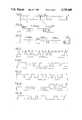
- FIGS. 2A to 2Hare time charts for describing the operation of the base station illustrated in FIG. 1;
- FIG. 3is a block diagram illustrating an embodiment of a paging receiver for use in the radio paging system according to the present invention
- FIGS. 4A to 4Fare time charts for describing the operation of the paging receiver illustrated in FIG. 3;
- FIGS. 5A to 5Eare time charts for describing the repetition period switching operation for battery saving by the paging receiver illustrated in FIG. 3.
- a subscriber's telephone set 1is connected to a trunk 31 in an encoding unit 3 through a telephone exchange 2.
- a register 33counts the calling signals received from the trunk 31, and converts a personal paging receiver's call number, transmitted from the calling party's telephone set 1, into a binary-coded decimal (BCD) number.
- a set call switch 32permits an operator's manual entry of the receiver's number into the register 33.
- a memory circuit 35stores the BCD number coming from the register 33.
- a BCD converter 36converts the BCD number, supplied from the memory circuit 35 into a binary code.
- An encoding circuit 41adds parity check bits to the output signal from the code converter 36 to provide a cyclic code.
- a preamble code generator 37repeatedly generates a unique word for a predetermined first duration of time (sufficient to repeat the generation 9 times in this instance) or second duration of time to repeat the generation 1,025 times).
- a sync code generator 38generates a sync code to follow the unique word.
- a battery saving period switching (BSPS) code generator 39generates a BSPS code to follow the sync code.
- An end code generator 40generates an end code.
- a timing signal generator circuit 34individually controls the circuits 35, 36, 37, 38, 39, 40 and 41, OR gates 42 and 43, and NAND gates 44 and 45, and supplies an encoding unit output through another NAND gate 46, to a transmitter 5.
- the transmitter 5comprises an FSK modulator 51, a frequency converter 52, a power amplifier 53 and an antenna 54.
- an ordinary telephone subscriberdials on telephone set 1 the call number assigned for the paging receiver.
- the dial signalis inputted to the trunk 31 via the exchange 2, and further to the register 33. It also is possible for an operator to operate manually the set call switch 32 to enter the call number into the register 33.
- the register 33having received a predetermined number of calls (for example, four), transfers to the memory circuit 35 all the call numbers, converted into BCD numbers.
- the memory circuit 35keeps the call numbers until a read signal comes from the timing circuit 34.
- the capacity of the memory circuit 35 in this embodimentis 80 calls.
- the timing circuit 34activates the preamble code generator 37 to supply the preamble code to the transmitter 5 via the OR gate 42 and NAND gates 44 and 46.
- the preamble code generator 37has a 31-bit counter (which is activated by the output of the timing circuit 34,) a unique word supply counter, and a read-only-memory (ROM, for instance ⁇ PD501D manufactured and marketed by NEC Corporation) in which the code pattern of FIG. 2D is set in advance.
- This preamble code generator 37reads out the contents of the ROM in response to the output of the 31-bit counter, and further repeats the reading of the ROM's contents, the number of repetitions being set by the unique word supply counter.
- the timing circuit 34activates the sync code generator 38 to supply the sync code, which consists of the code pattern of FIG.
- call numbersare stored in the memory circuit 35, these numbers are transferred to the code converter 36 one by one, in the order of their storage, in response to the read signal from the timing circuit 34, until the memory circuit 35 is cleared.
- the code converter 36converts BCD numbers into 21-bit binary codes.
- the cncoder 41adds 10 parity check bits to the 21-bit information codes to supply an address number word representative of a the call number and consisting of the Bose-Chaudhuri Hocqunghen BCH (31, 21) cyclic code, to the transmitter 5 via the NAND gates 45 and 46.
- An example of code pattern of address number wordsis shown in FIG. 2G. As illustrated in FIG. 2B at most, 80 address number words, from #2 to #1 in that order, are supplied consecutively.
- the encoding circuit 41may be composed of shift registers and adders as described in Wesley Peterson, "Error-Correcting Codes," pp. 149-152 (1962, The M.I.T. Press.)
- the timing circuit 34then suspends the operation of this the circuits 35, 36 and 41, and at the same time activate the end code generator 40 to send the end code E to the transmitter 5 via the OR gates 42 and 43 and the NAND gates 44 and 46, as shown in FIGS. 2A and 2B.
- the one-word code pattern of the end code Eshown in FIG. 2H, is a pseudonoise (PN) pattern consisting of 31 bits.
- PNpseudonoise
- the timing circuit 34After the end code generator 40 has supplied code, the timing circuit 34 starts its built-in timer. In this embodiment, this timer is set to 2 minutes and 38.72 seconds (1,024 words ⁇ 155 msec). If there is a new call number from the memory circuit 35 within this period of time, the timing circuit 34 repeats the foregoing series of actions. The sequence of signals at this time is shown in FIG. 2A.
- the timing circuit 34acts to change the battery saving repetition period.
- the timing circuit 34starts the preamble code generator 37 to supply nine unique words similar to code P in FIG. 2B, and then enables the sync code generator 38 to supply the one-word sync code shown in FIG. 2E.
- the timing circuit 34starts the BSPS code generator 39 to supply at least one word of BSPS code consisting of the 31-bit pattern shown in FIG. 2F, and then starts the end code generator 40 to supply two words of the end code of FIG. 2H.
- the timing circuit 34generates no output unless a new call number is supplied to the memory circuit 35.
- the timing circuit 34starts the preamble code generator 37.
- the timing circuit 34changes from 9 to 1,025 the count of the unique word supply counter within the preamble code generator 37, so that 1,025 unique words (P' in FIG. 2C) are supplied from the preamble code generator 37.
- the timing circuit 34suspends signal supply for a nine-word length of time, re-starts the preamble code generator 37, and at the same time changes from 1,025 to 9 the count of the unique word supply counter within the preamble code generator 37 by supplying the unique word supply counter switching signal, so that the signal sequence of FIG. 2B is supplied.
- the aforementioned signal sequenceis illustrated in FIG. 2C.
- the transmitter 5transmits through the antenna 54 a carrier wave modulated with an output signal sequence provided from the encoder unit 3.
- FIG. 3is a circuit diagram illustrating a paging receiver according to the present invention. The operation of this receiver will be described below with reference to time charts of FIG. 4.
- a modulated carrier wave transmitted from the transmitter 5 on the base station sideis picked up by an antenna 100, and received and demodulated by a receiving section 200 to be converted into a baseband signal.
- This baseband signalis shaped by a waveform shaping circuit 300 into a rectangular wave, which is supplied to a signal selecting circuit 400.
- These operationsare, performed during a period of 2t (where t is one-word length of time) while every part of the receiver is supplied with power.
- the receiving section 200 and the waveform shaping circuit 300are not supplied with power.
- This 2t on/5t off cyclerepresents one mode of the receiver's battery-saving function, as shown in FIG. 4B, and which will be described below in greater detail.
- a bit-sync circuit 410regenerates a clock signal which is bit-synchronized with the demodulated signal, and supplies the clock signal by way of a line 900 to a preamble code detector 420, a sync code detector 430, an end code detector 440 and an address code detector 450.
- the ouput of the waveform shaping circuit 300is supplied to one input of the preamble code detector 420 through an AND gate 486.
- the other input of this AND gate 486is connected to the Q output of a flip-flop (F/F) 730 within a pulser circuit 700.
- the Q output of the F/F 730is high only when the battery saving function is turned on, but it is low when the function is turned off. Therefore, the signal to the preamble code detector 420 is given only when the battery saving function is on.
- the detector 420Upon detection of the preamble code, the detector 420 provides the detection pulse of FIG. 4C at a connection line 901.
- the F/F 730 of the pulser circuit 700is set by this detection pulse, and the Q output of the F/F 730, passing through a NOR gate 740, keeps a switching transistor 750 turned on.
- the pulse, shown in FIG. 4C. of the line 901also starts a timer 460 which, in response to the clock signal from the line 900, begins counting the time. This timer 460 is set for a period of 9t (the third duration of time), as shown in FIG. 4B.
- a time-out signalis outputted to a line 902 and resets the F/F 730 through an OR gate 490.
- the Q output of the F/f 730becomes low and turns off the switching transistor 750 via the NOR gate 740 to turn on the receiver's battery saving function again.
- the Q output of the F/F 730becomes high, and the AND gate 486 opens.
- a detection pulseis outputted to a line 903.
- This detection pulseresets the timer 460 via the line 903, and at the same time causes a timer 470 to start counting.
- the timer 470is set so that the fourth duration of time is 80t, as shown in FIG. 4B.
- the switching transistor 750is turned off, as occurs in the case of the timer 460 after 9t has elapsed, and the receiver's battery-saving function operates again, in the above-mentioned 2t on/5t off cycle.
- the circuit structures of the preamble code detector 420, the sync code detector 430 and the end code detector 440are similar, so the structure of the sync code detector 430 now will be described as representative of the three.
- the sync code of FIG. 2Eis provided to a 31-bit shift register 434.
- the 31-bit output of the shift register 434is supplied to an AND gate 435 directly when the corresponding bits of the sync code are "1," and through inverters 431, 432, 433 and so on when the corresponding bits of the same are "0". Only when the 31 bits supplied to the shift register 434 are respectively identical to the 31 bits of the sync code does the AND gate 435 pass a detection pulse (FIG. 4D) through the line 903.
- the preamble code detector 420, sync code detector 430 and end code detector 440differ from one another only in the positions of inverters arranged to match the "0" in the code patterns of FIGS. 2D, 2E and 2H.
- the address code detector 450will output a detection pulse shown in FIG. 4E over a line 904, and this pulse is supplied to an alert tone generator 500 to activate it.
- the generator 500outputs a continuous alert, as shown in FIG. 4F, which drives a speaker 600 to let the receiver's bearer know that s/he is being paged.
- ⁇indicates a time at which a reset switch 501 is pressed to stop the alert tone.
- a sync code detection pulse(See FIG. 4D) at the line 903 activates a read pulse generator 454, comprising a 31-bit shift register, to generate sequentially and cyclically at output terminals #1-31 the read pulses synchronized with the clock signal from the line 900.
- a read pulse generator 454comprising a 31-bit shift register, to generate sequentially and cyclically at output terminals #1-31 the read pulses synchronized with the clock signal from the line 900.
- a programmable read-only memory (PROM) 453the address code assigned to the paging receiver is written in advance.
- the PROMmay be of the so-called detachable cord-plug type.
- the first bit of the address code stored in the PROM 453is read out, and supplied to one of the input terminals of a two-input exclusive NOR gate 451.
- An output from the waveform shaping circuit 300is supplied to the other input terminal of the gate 451.
- This gate 451is open if the two inputs are the same, or closed if they are different.
- a 31-bit counter 452counts the pulses when the gate 451 is open.
- the counter 452Since the clock signal from the line 900 is supplied to the counter 452, if each respective pair of one of the consecutive bits from the PROM 453 and one of the outputs of the waveform shaping circuit 300 is found by the exclusive NOR gate 451 to be identical the counter 452 will count up sequentially until the 31st bit and, if all the 31 bits are found to be identical will, supply a detection pulse (FIG. 4E) over the line 904. Then the counter 452 is reset by the trailing edge of the read pulse of 31st bit to prepare itself for the next counting.
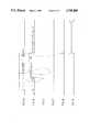
- FIG. 5Ashows a modulated carrier wave transmitted from the base station.
- the base station's transmitter 5sends a nine-word (9t) preamble code (P in FIG. 5A), followed by a one-word sync code (1 in FIG. 5A), a one-word battery saving period switching (BSPS) signal (2 in FIG. 5A) and a two-word end code (E if FIG. 5A).
- P in FIG. 5Anine-word preamble code
- BSPSbattery saving period switching
- Etwo-word end code
- FIG. 5BThe battery saving operation of the paging receiver shown in FIG. 3, corresponding to the modulated carrier wave of FIG. 5A, is represented by FIG. 5B.
- the receiving section 200 and the waveform shaping circuit 300, regulated by the pulser circuit 700,are repeatedly turning on (for 2t) and off (for 5t) as shown in FIG. 5B.
- a detection pulseis generated at point c 1 of FIG. 5C.
- the timer 460sets a third duration of time 9t as shown in FIG. 5B.
- a sync codeas described with reference to FIG.
- a battery saving period switching (BSPS) signal 2shwon in FIG. 5A, is detected by a BSPS signal detector 480 (see FIG. 3), and a detection pulse of FIG. 5E is outputted over the line 905.
- the pulse on the line 905resets the timer 470 by way of an OR gate 485, resets the F/F 730 by way of the OR gate 490, and inverts its Q output to below.
- the switching transistor 750is turned off via the NOR gate 740. Again the receiver's battery-saving function is thereby rendered operational.
- the detection pulse on the line 905also sets a F/F 760, and inverts the outputs Q and Q.
- the outputs Q and Q of the F/F 760are connected to AND gate 780 to keep it closed, and to AND gate 770 to keep it open.
- a control signalis fed to the other input terminal of the AND gate 770 at a repetition period represented by ⁇ 2 in FIG. 5B, while a control signal is fed to the other input terminal of the AND gate 780 at a repetition period represented by ⁇ 1 in FIG. 5B.
- These control signalsare supplied from a control signal generator 720, which frequency-divides the output of an oscillator 710 to generate the required control signals at the repetition periods ⁇ 1 and ⁇ 2 .
- the pulse to reset and initialize the control signal generator 720is obtained by inverting the output Q of the F/F 730 with an inverter 790. Consequently, the NOR gate 740 is controlled by the output of the AND gate 770, and repeatedly turns on and off the switching transistor 750 at the repetition period of ⁇ 2 .
- the repetition period ⁇ 2represents another mode of the receiver's battery-saving function, as will be described below.
- the repetition periodis ⁇ 2
- poweris supplied to all parts of the receiver for 2t; for the following 1021t, power is not supplied to the receiving section 200 and waveform shaping circuit 300.
- the average current of the receiving section 200 and the waveform shaping circuit 300is 3 mA and that of the signal selecting circuit 400 and the pulser circuit 700 is 150 ⁇ A
- the average current during the period ⁇ 1is ##EQU1## Accordingly, the amperage for the paging of the present invention is only 16 percent of that involved if there were no switching of repetition period from ⁇ 1 to ⁇ 2 .
- the preamble code detector 420outputs the detection pulse to the line 901 at point c 2 in FIG. 5C.
- the pulse on the line 901resets the F/F 760 and inverts to outputs Q and Q.
- the AND gate 780is opened, and the AND gate 770 is closed, the battery saving period changing from ⁇ 2 to ⁇ 1 . Since the pulse on the line 901 (at point c 2 in FIG. 5C) induces actions similar to those described with reference to point c 1 in FIG. 5C, battery saving is suspended for a period of 9t.
- the receiverresumes battery saving in response to a time-out signal from the timer 460.
- a 9t pauseis provided between preamble codes P' and P on the base station side to ensure the possibility of suspending battery saving, which might otherwise be impossible if the preamble code P arrives immediately following the code P' within the 9t period during which the receiver is waiting for a sync code.
- an end code E(see FIG. 2H) is transmitted to let the paging receiver resume battery saving by detecting the end code with the end code detector 440 and resetting the F/F 730 via the OR gates 485 and 490 in response to the end code detection pulse, so that the paging receiver may take no unnecessary receiving action when the address code transmission from the base station is less than 80t.
- the preamble codecan obviously be replaced with any other code different from the sync code, battery saving period switching code, end code, and address code.
- the period ⁇ 2can be extended by grouping the paging receivers.
- the call number capacityis the 21st power of 2 (equal to 2097152) because the call number code has 21 information bits, as shown in FIG. 2G.
- these 2097152 different call numberscan be grouped into 200 groups, each of which has 10,000 call numbers and is headed with a preamble code unique thereto.
- the encoding unitcomprises a sorter provided between the trunk 31 and the register 33 (See FIG. 1) with which the call numbers are sorted into prefixed groups.
- the encoding unitincludes the register 33, the decimal-binary converter 36 and the encoder 41 (See FIG. 1).
- the encoding unitalso comprises a transmission sequence arranging circuit following the NAND gate 46 to arrange the encoded group paging codes from the encoders 41 to a paging code.
- each paging receiver which is in a given grouphas to have a preamble code detector unique to the given group.
- this unique preamble code detectormakes the paging receiver design somewhat complex, composing the decoder of a PROM of the code-plug type in the same manner as the address code detector 450 (FIG. 3) will simplify the design, and if these preamble and address code detectors are placed in a single PROM, the design will be even simpler.
- the radio paging systemsets more than one duration and repetition period for battery saving pulses for the paging receiver, resulting in the reduction of the paging receiver's power consumption.
- the power switch of the paging receivercan be eliminated so that the receiver is more compact and is easier to operate.
Landscapes
- Engineering & Computer Science (AREA)
- Computer Networks & Wireless Communication (AREA)
- Signal Processing (AREA)
- Physics & Mathematics (AREA)
- Electromagnetism (AREA)
- General Physics & Mathematics (AREA)
- Mobile Radio Communication Systems (AREA)
Abstract
Description
Claims (10)
Applications Claiming Priority (4)
| Application Number | Priority Date | Filing Date | Title |
|---|---|---|---|
| JP58061522AJPS59188247A (en) | 1983-04-09 | 1983-04-09 | Battery saving system |
| JP58061523AJPS59188248A (en) | 1983-04-09 | 1983-04-09 | Receiver for individual selective call |
| JP58-61523 | 1983-04-09 | ||
| JP58-61522 | 1983-04-09 |
Publications (1)
| Publication Number | Publication Date |
|---|---|
| US4745408Atrue US4745408A (en) | 1988-05-17 |
Family
ID=26402563
Family Applications (1)
| Application Number | Title | Priority Date | Filing Date |
|---|---|---|---|
| US06/597,788Expired - LifetimeUS4745408A (en) | 1983-04-09 | 1984-04-06 | Radio paging system and receiver therefor |
Country Status (4)
| Country | Link |
|---|---|
| US (1) | US4745408A (en) |
| EP (1) | EP0124788B1 (en) |
| CA (1) | CA1231390A (en) |
| DE (1) | DE3473369D1 (en) |
Cited By (54)
| Publication number | Priority date | Publication date | Assignee | Title |
|---|---|---|---|---|
| US4802240A (en)* | 1986-07-03 | 1989-01-31 | Kokusai Denki Kabushiki Kaisha | Synchronous receiving method for selective calling signal |
| US4933963A (en)* | 1987-11-30 | 1990-06-12 | Kabushiki Kaisha Toshiba | Radio telephone apparatus |
| GB2226475A (en)* | 1988-12-23 | 1990-06-27 | Philips Electronic Associated | Power economising in multiple user radio systems |
| WO1991006188A1 (en)* | 1989-10-17 | 1991-05-02 | At&E Corporation | Adaptive on-off control for radio receiver |
| US5032835A (en)* | 1989-04-24 | 1991-07-16 | Motorola, Inc. | Out of range indication for radio receivers |
| WO1991019358A1 (en)* | 1990-06-05 | 1991-12-12 | Motorola, Inc. | Time based signal detector |
| US5168493A (en)* | 1990-01-02 | 1992-12-01 | Motorola, Inc. | Time division multiplexed selective call system |
| US5224152A (en)* | 1990-08-27 | 1993-06-29 | Audiovox Corporation | Power saving arrangement and method in portable cellular telephone system |
| US5227777A (en)* | 1988-12-06 | 1993-07-13 | Nec Corporation | Radio paging receiver for intermittently receiving a paging signal transmitted on different phases of a clock |
| US5251325A (en)* | 1990-06-04 | 1993-10-05 | Motorola, Inc. | Battery saving method and apparatus for providing selective receiver power switching |
| US5309153A (en)* | 1985-11-27 | 1994-05-03 | Seiko Corp. | Adaptive on-off control for radio receiver |
| US5361397A (en)* | 1991-08-26 | 1994-11-01 | Motorola, Inc. | Communication device and system capable of automatic programmable energizing |
| US5373506A (en)* | 1990-11-26 | 1994-12-13 | Motorola Inc. | Method and apparatus for paging in a communication system |
| US5414419A (en)* | 1989-12-04 | 1995-05-09 | Motorola, Inc. | Battery saving method for selective call receivers |
| EP0611124A3 (en)* | 1993-02-10 | 1995-08-30 | Data Critical Corp | Paging transmission system. |
| US5537100A (en)* | 1994-04-06 | 1996-07-16 | Sharp Microelectronics Technology, Inc. | System and method for analyzing coded transmission sent to mobile message receivers |
| US5566081A (en)* | 1992-10-23 | 1996-10-15 | Nec Corporation | Method of saving power consumption in a battery operated pager receiver |
| US5590396A (en)* | 1994-04-20 | 1996-12-31 | Ericsson Inc. | Method and apparatus for a deep-sleep mode in a digital cellular communication system |
| US5722065A (en)* | 1993-08-27 | 1998-02-24 | Ntt Mobile Communications Network, Inc. | Mobile communications system and mobile receiver |
| US5721744A (en)* | 1996-02-20 | 1998-02-24 | Sharp Microelectronics Technology, Inc. | System and method for correcting burst errors in digital information |
| US5760699A (en)* | 1995-03-06 | 1998-06-02 | Seiko Instruments, Inc. | Method and apparatus for receiving selected paging signal |
| US5920581A (en)* | 1996-05-31 | 1999-07-06 | Vtech Communications, Ltd. | Error detection method and apparatus for digital communication data packets |
| US5956377A (en)* | 1996-05-31 | 1999-09-21 | Vtech Communications, Ltd. | Method and apparatus for synchronizing frames within a continuous stream of digital data |
| US5995554A (en)* | 1996-06-03 | 1999-11-30 | Vtech Communications, Ltd. | Data framing format for digital radio communications and method of forming same |
| US6005885A (en)* | 1995-12-12 | 1999-12-21 | Intermec Ip Corp. | Methodology for discontinuous radio reception utilizing embedded frame length words |
| US6009119A (en)* | 1997-03-25 | 1999-12-28 | Intermec Ip Corp. | Adaptive power leveling of an RF transceiver utilizing information stored in non-volatile memory |
| USRE36712E (en)* | 1987-11-30 | 2000-05-23 | Kabushiki Kaisha Toshiba | Radio telephone apparatus |
| US6075807A (en)* | 1997-03-25 | 2000-06-13 | Intermec Ip Corp. | Windowed digital matched filter circuit for power reduction in battery-powered CDMA radios |
| US6119024A (en)* | 1997-07-25 | 2000-09-12 | Nec Corporation | Mobile radio system |
| US6141373A (en)* | 1996-11-15 | 2000-10-31 | Omnipoint Corporation | Preamble code structure and detection method and apparatus |
| US6154486A (en)* | 1995-06-05 | 2000-11-28 | Omnipoint Corporation | Preamble code structure and detection method and apparatus |
| US6219540B1 (en) | 1998-11-23 | 2001-04-17 | Motorola, Inc. | Communication device providing out-of-range battery saving and method therefor |
| US6264614B1 (en) | 1999-08-31 | 2001-07-24 | Data Critical Corporation | System and method for generating and transferring medical data |
| CN1080075C (en)* | 1995-03-06 | 2002-02-27 | 精工电子工业株式会社 | Method and equipment for receiving selective paging signal |
| US6356607B1 (en)* | 1995-06-05 | 2002-03-12 | Omnipoint Corporation | Preamble code structure and detection method and apparatus |
| US20020154720A1 (en)* | 1997-06-30 | 2002-10-24 | Krasner Norman Franklin | Combined preamble detection and information transmission method for burst-type digital communication systems |
| US20030008675A1 (en)* | 2001-05-04 | 2003-01-09 | Robin Willats | Scanning device |
| US20030054785A1 (en)* | 2001-01-09 | 2003-03-20 | Wolfgang Tobergte | Method and circuit arrangement for detecting synchronization patterns in a receiver |
| US20040023651A1 (en)* | 1991-05-13 | 2004-02-05 | Gollnick Charles D. | Network supporting roaming, sleeping terminals |
| US20040023617A1 (en)* | 1991-05-13 | 2004-02-05 | Mahany Ronald L. | Radio frequency local area network |
| US6707867B2 (en) | 1993-03-06 | 2004-03-16 | Agere Systems, Inc. | Wireless local area network apparatus |
| US20040166895A1 (en)* | 1993-08-31 | 2004-08-26 | Koenck Steven E. | Modular, portable data processing terminal for use in a communication network |
| US20050078647A1 (en)* | 1991-10-01 | 2005-04-14 | Meier Robert C. | Radio frequency local area network |
| US20050159152A1 (en)* | 2003-12-16 | 2005-07-21 | Honeywell International, Inc. | Synchronized wireless communications system |
| US20050163088A1 (en)* | 2004-01-27 | 2005-07-28 | Nec Corporation | Radio communication method, radio communication system and wireless terminal |
| US20060068715A1 (en)* | 2004-09-30 | 2006-03-30 | Hundal Sukhdeep S | System and method for asymmetric enhanced mode operation in a digital communication system |
| US7027424B1 (en) | 2000-05-24 | 2006-04-11 | Vtech Communications, Ltd. | Method for avoiding interference in a digital communication system |
| USRE40111E1 (en)* | 1988-11-02 | 2008-02-26 | M & Fc Holding, Llc | Wireless alarm system |
| US20090092070A1 (en)* | 1992-11-02 | 2009-04-09 | Broadcom Corporation | Radio frequency local area network |
| US20100046498A1 (en)* | 2008-08-19 | 2010-02-25 | Steven Hall | Method and system for sleep mode signaling for a multi-standard system with bluetooth |
| US20100128621A1 (en)* | 2007-04-27 | 2010-05-27 | Nec Corporation | Communication system, base station, mobile station, communication method, and program |
| US7899951B2 (en) | 1991-05-13 | 2011-03-01 | Broadcom Corporation | Communication network having a plurality of bridging nodes which transmits a polling message with backward learning technique to determine communication pathway |
| US8160034B1 (en) | 2008-09-09 | 2012-04-17 | Sprint Spectrum L.P. | Dynamic determination of EV-DO control-channel bit rate based on forward-link-timeslot utilization, control-channel occupancy, and amount of buffered forward-link traffic data |
| US8358633B1 (en)* | 2006-11-08 | 2013-01-22 | Sprint Spectrum L.P. | Dynamic determination of EV-DO control-channel bit rate based on forward-link timeslot utilization |
Families Citing this family (9)
| Publication number | Priority date | Publication date | Assignee | Title |
|---|---|---|---|---|
| US5150954A (en)* | 1984-12-05 | 1992-09-29 | Seiko Corporation | Pager watch system utilizing time slot communication |
| EP0184606A3 (en)* | 1984-12-05 | 1988-03-30 | A.T. & E. LABORATORIES, INC. | Pager watch system utilizing time slot communication |
| AU6403586A (en)* | 1985-08-08 | 1987-03-05 | Metrocast | Scanning receiver for nationwide radio paging system |
| JPH06101698B2 (en)* | 1986-04-25 | 1994-12-12 | 日本電気株式会社 | Wireless telephone |
| JPH02500154A (en)* | 1987-01-02 | 1990-01-18 | モトローラ・インコーポレーテッド | Paging system with assignable battery saver duty cycle |
| US5247700A (en)* | 1990-11-16 | 1993-09-21 | Universal Cellular, Inc. | Cellular telephone with pager |
| TW198782B (en)* | 1991-11-26 | 1993-01-21 | Samsung Electronics Co Ltd | |
| US6560461B1 (en) | 1997-08-04 | 2003-05-06 | Mundi Fomukong | Authorized location reporting paging system |
| CN104184672A (en)* | 2014-09-10 | 2014-12-03 | 四川九洲电器集团有限责任公司 | Method and device of transmitting message |
Citations (7)
| Publication number | Priority date | Publication date | Assignee | Title |
|---|---|---|---|---|
| US4194153A (en)* | 1977-09-16 | 1980-03-18 | Nippon Electric Co., Ltd. | Digital radio paging communication system |
| US4353065A (en)* | 1980-03-28 | 1982-10-05 | Nippon Electric Co., Ltd. | Digital radio paging communication system |
| US4370753A (en)* | 1975-06-26 | 1983-01-25 | Motorola, Inc. | Battery saver for a tone coded signalling system |
| US4385398A (en)* | 1979-06-07 | 1983-05-24 | Keith H. Wycoff | Selective call communication receiver |
| US4398192A (en)* | 1981-12-04 | 1983-08-09 | Motorola Inc. | Battery-saving arrangement for pagers |
| US4449248A (en)* | 1982-02-01 | 1984-05-15 | General Electric Company | Battery saving radio circuit and system |
| US4479261A (en)* | 1982-04-19 | 1984-10-23 | Nec Corporation | Battery saving circuit for paging receiver |
- 1984
- 1984-04-06USUS06/597,788patent/US4745408A/ennot_activeExpired - Lifetime
- 1984-04-09DEDE8484103948Tpatent/DE3473369D1/ennot_activeExpired
- 1984-04-09CACA000451546Apatent/CA1231390A/ennot_activeExpired
- 1984-04-09EPEP84103948Apatent/EP0124788B1/ennot_activeExpired
Patent Citations (7)
| Publication number | Priority date | Publication date | Assignee | Title |
|---|---|---|---|---|
| US4370753A (en)* | 1975-06-26 | 1983-01-25 | Motorola, Inc. | Battery saver for a tone coded signalling system |
| US4194153A (en)* | 1977-09-16 | 1980-03-18 | Nippon Electric Co., Ltd. | Digital radio paging communication system |
| US4385398A (en)* | 1979-06-07 | 1983-05-24 | Keith H. Wycoff | Selective call communication receiver |
| US4353065A (en)* | 1980-03-28 | 1982-10-05 | Nippon Electric Co., Ltd. | Digital radio paging communication system |
| US4398192A (en)* | 1981-12-04 | 1983-08-09 | Motorola Inc. | Battery-saving arrangement for pagers |
| US4449248A (en)* | 1982-02-01 | 1984-05-15 | General Electric Company | Battery saving radio circuit and system |
| US4479261A (en)* | 1982-04-19 | 1984-10-23 | Nec Corporation | Battery saving circuit for paging receiver |
Non-Patent Citations (2)
| Title |
|---|
| "Error-Correcting Codes" by Wesley Peterson, The M.I.T. Press, 1962, pp. 149-152. |
| Error Correcting Codes by Wesley Peterson, The M.I.T. Press, 1962, pp. 149 152.* |
Cited By (89)
| Publication number | Priority date | Publication date | Assignee | Title |
|---|---|---|---|---|
| US5309153A (en)* | 1985-11-27 | 1994-05-03 | Seiko Corp. | Adaptive on-off control for radio receiver |
| US4802240A (en)* | 1986-07-03 | 1989-01-31 | Kokusai Denki Kabushiki Kaisha | Synchronous receiving method for selective calling signal |
| US4933963A (en)* | 1987-11-30 | 1990-06-12 | Kabushiki Kaisha Toshiba | Radio telephone apparatus |
| USRE36712E (en)* | 1987-11-30 | 2000-05-23 | Kabushiki Kaisha Toshiba | Radio telephone apparatus |
| USRE40111E1 (en)* | 1988-11-02 | 2008-02-26 | M & Fc Holding, Llc | Wireless alarm system |
| US5227777A (en)* | 1988-12-06 | 1993-07-13 | Nec Corporation | Radio paging receiver for intermittently receiving a paging signal transmitted on different phases of a clock |
| GB2226475A (en)* | 1988-12-23 | 1990-06-27 | Philips Electronic Associated | Power economising in multiple user radio systems |
| US5032835A (en)* | 1989-04-24 | 1991-07-16 | Motorola, Inc. | Out of range indication for radio receivers |
| WO1991006188A1 (en)* | 1989-10-17 | 1991-05-02 | At&E Corporation | Adaptive on-off control for radio receiver |
| US5414419A (en)* | 1989-12-04 | 1995-05-09 | Motorola, Inc. | Battery saving method for selective call receivers |
| US5168493A (en)* | 1990-01-02 | 1992-12-01 | Motorola, Inc. | Time division multiplexed selective call system |
| US5371737A (en)* | 1990-01-02 | 1994-12-06 | Motorola Inc. | Selective call receiver for receiving a multiphase multiplexed signal |
| US5392457A (en)* | 1990-06-04 | 1995-02-21 | Motorola, Inc. | Battery saving method and apparatus for providing selective receiver power switching |
| US5251325A (en)* | 1990-06-04 | 1993-10-05 | Motorola, Inc. | Battery saving method and apparatus for providing selective receiver power switching |
| WO1991019358A1 (en)* | 1990-06-05 | 1991-12-12 | Motorola, Inc. | Time based signal detector |
| US5140702A (en)* | 1990-06-05 | 1992-08-18 | Motorola, Inc. | Time based signal detector for operating in a presence search mode and absence search mode during peak times and off peak times |
| US5224152A (en)* | 1990-08-27 | 1993-06-29 | Audiovox Corporation | Power saving arrangement and method in portable cellular telephone system |
| US5373506A (en)* | 1990-11-26 | 1994-12-13 | Motorola Inc. | Method and apparatus for paging in a communication system |
| US7826818B2 (en) | 1991-05-13 | 2010-11-02 | Broadcom Corporation | Network supporting roaming, sleeping terminals |
| US7552246B2 (en) | 1991-05-13 | 2009-06-23 | Broadcom Corporation | Communication network having a plurality of bridging nodes which transmit a beacon to terminal nodes in power saving state that it has messages awaiting delivery |
| US7536167B2 (en) | 1991-05-13 | 2009-05-19 | Broadcom Corporation | Network supporting roaming, sleeping terminals |
| US7899951B2 (en) | 1991-05-13 | 2011-03-01 | Broadcom Corporation | Communication network having a plurality of bridging nodes which transmits a polling message with backward learning technique to determine communication pathway |
| US7457646B2 (en) | 1991-05-13 | 2008-11-25 | Broadcom Corporation | Radio frequency local area network |
| US20050086399A1 (en)* | 1991-05-13 | 2005-04-21 | Mahany Ronald L. | Radio frequency local area network |
| US20040073933A1 (en)* | 1991-05-13 | 2004-04-15 | Gollnick Charles D. | Network supporting roaming, sleeping terminals |
| US20040023617A1 (en)* | 1991-05-13 | 2004-02-05 | Mahany Ronald L. | Radio frequency local area network |
| US20040023651A1 (en)* | 1991-05-13 | 2004-02-05 | Gollnick Charles D. | Network supporting roaming, sleeping terminals |
| US5361397A (en)* | 1991-08-26 | 1994-11-01 | Motorola, Inc. | Communication device and system capable of automatic programmable energizing |
| US7483397B2 (en) | 1991-10-01 | 2009-01-27 | Broadcom Corporation | Radio frequency local area network |
| US20090172189A1 (en)* | 1991-10-01 | 2009-07-02 | Broadcom Corporation | Radio frequency local area network |
| US20060268806A1 (en)* | 1991-10-01 | 2006-11-30 | Meier Robert C | Radio frequency local area network |
| US7873343B2 (en) | 1991-10-01 | 2011-01-18 | Broadcom Corporation | Communication network terminal with sleep capability |
| US20050078647A1 (en)* | 1991-10-01 | 2005-04-14 | Meier Robert C. | Radio frequency local area network |
| US5566081A (en)* | 1992-10-23 | 1996-10-15 | Nec Corporation | Method of saving power consumption in a battery operated pager receiver |
| US7917145B2 (en) | 1992-11-02 | 2011-03-29 | Broadcom Corporation | Radio frequency local area network |
| US20090092070A1 (en)* | 1992-11-02 | 2009-04-09 | Broadcom Corporation | Radio frequency local area network |
| US20090323589A1 (en)* | 1992-11-02 | 2009-12-31 | Broadcom Corporation | Radio frequency local area network |
| EP0611124A3 (en)* | 1993-02-10 | 1995-08-30 | Data Critical Corp | Paging transmission system. |
| US7010058B2 (en) | 1993-03-06 | 2006-03-07 | Agere Systems Inc. | Wireless local area network apparatus |
| US7289578B2 (en) | 1993-03-06 | 2007-10-30 | Agere Systems Inc. | Wireless local area network apparatus |
| US20080037467A1 (en)* | 1993-03-06 | 2008-02-14 | Agere Systems Inc. | Wireless local area network apparatus |
| US20060121861A1 (en)* | 1993-03-06 | 2006-06-08 | Diepstraten Wilhelmus J M | Wireless local area network apparatus |
| US7421038B2 (en) | 1993-03-06 | 2008-09-02 | Agere Systems Inc. | Wireless local area network apparatus |
| US20070237257A1 (en)* | 1993-03-06 | 2007-10-11 | Diepstraten Wilhelmus J M | Wireless local area network apparatus |
| US20040071246A1 (en)* | 1993-03-06 | 2004-04-15 | Diepstraten Wilhelmus J. M. | Wireless local area network apparatus |
| US6707867B2 (en) | 1993-03-06 | 2004-03-16 | Agere Systems, Inc. | Wireless local area network apparatus |
| US5722065A (en)* | 1993-08-27 | 1998-02-24 | Ntt Mobile Communications Network, Inc. | Mobile communications system and mobile receiver |
| US20040166895A1 (en)* | 1993-08-31 | 2004-08-26 | Koenck Steven E. | Modular, portable data processing terminal for use in a communication network |
| US8509260B2 (en) | 1993-08-31 | 2013-08-13 | Broadcom Corporation | Modular, portable data processing terminal for use in a communication network |
| US5537100A (en)* | 1994-04-06 | 1996-07-16 | Sharp Microelectronics Technology, Inc. | System and method for analyzing coded transmission sent to mobile message receivers |
| US5590396A (en)* | 1994-04-20 | 1996-12-31 | Ericsson Inc. | Method and apparatus for a deep-sleep mode in a digital cellular communication system |
| CN1080075C (en)* | 1995-03-06 | 2002-02-27 | 精工电子工业株式会社 | Method and equipment for receiving selective paging signal |
| KR100394829B1 (en)* | 1995-03-06 | 2003-11-17 | 세이코 인스트루먼트 가부시키가이샤 | Method of receiving selective calling signal and its receiving device |
| US5760699A (en)* | 1995-03-06 | 1998-06-02 | Seiko Instruments, Inc. | Method and apparatus for receiving selected paging signal |
| US6356607B1 (en)* | 1995-06-05 | 2002-03-12 | Omnipoint Corporation | Preamble code structure and detection method and apparatus |
| US6154486A (en)* | 1995-06-05 | 2000-11-28 | Omnipoint Corporation | Preamble code structure and detection method and apparatus |
| US6005885A (en)* | 1995-12-12 | 1999-12-21 | Intermec Ip Corp. | Methodology for discontinuous radio reception utilizing embedded frame length words |
| US5721744A (en)* | 1996-02-20 | 1998-02-24 | Sharp Microelectronics Technology, Inc. | System and method for correcting burst errors in digital information |
| US5920581A (en)* | 1996-05-31 | 1999-07-06 | Vtech Communications, Ltd. | Error detection method and apparatus for digital communication data packets |
| US5956377A (en)* | 1996-05-31 | 1999-09-21 | Vtech Communications, Ltd. | Method and apparatus for synchronizing frames within a continuous stream of digital data |
| US5995554A (en)* | 1996-06-03 | 1999-11-30 | Vtech Communications, Ltd. | Data framing format for digital radio communications and method of forming same |
| US6141373A (en)* | 1996-11-15 | 2000-10-31 | Omnipoint Corporation | Preamble code structure and detection method and apparatus |
| US6075807A (en)* | 1997-03-25 | 2000-06-13 | Intermec Ip Corp. | Windowed digital matched filter circuit for power reduction in battery-powered CDMA radios |
| US6009119A (en)* | 1997-03-25 | 1999-12-28 | Intermec Ip Corp. | Adaptive power leveling of an RF transceiver utilizing information stored in non-volatile memory |
| US6947489B2 (en)* | 1997-06-30 | 2005-09-20 | Gilat Satellite Networks, Ltd. | Combined preamble detection and information transmission method for burst-type digital communication systems |
| US20020154720A1 (en)* | 1997-06-30 | 2002-10-24 | Krasner Norman Franklin | Combined preamble detection and information transmission method for burst-type digital communication systems |
| US6119024A (en)* | 1997-07-25 | 2000-09-12 | Nec Corporation | Mobile radio system |
| US6219540B1 (en) | 1998-11-23 | 2001-04-17 | Motorola, Inc. | Communication device providing out-of-range battery saving and method therefor |
| US6685633B2 (en) | 1999-08-31 | 2004-02-03 | Ge Medical Systems Information Technologies, Inc. | System and method for generating and transferring data |
| US6264614B1 (en) | 1999-08-31 | 2001-07-24 | Data Critical Corporation | System and method for generating and transferring medical data |
| US20060120333A1 (en)* | 2000-05-24 | 2006-06-08 | Dion Horvat | Method for avoiding interference in a digital communication system |
| US7027424B1 (en) | 2000-05-24 | 2006-04-11 | Vtech Communications, Ltd. | Method for avoiding interference in a digital communication system |
| US8531998B2 (en) | 2000-05-24 | 2013-09-10 | Vtech Communications, Ltd. | Communications apparatus and method to avoid interference |
| US7990933B2 (en) | 2000-05-24 | 2011-08-02 | Vtech Communications, Ltd. | Method for avoiding interference in a digital communication system |
| US7099423B2 (en) | 2001-01-09 | 2006-08-29 | Koninklijke Philips Electronics N.V. | Method and circuit arrangement for detecting synchronization patterns in a receiver |
| US20030054785A1 (en)* | 2001-01-09 | 2003-03-20 | Wolfgang Tobergte | Method and circuit arrangement for detecting synchronization patterns in a receiver |
| US20030008675A1 (en)* | 2001-05-04 | 2003-01-09 | Robin Willats | Scanning device |
| US7814188B2 (en) | 2003-12-16 | 2010-10-12 | Honeywell International Inc. | Synchronized wireless communications system |
| US20050159152A1 (en)* | 2003-12-16 | 2005-07-21 | Honeywell International, Inc. | Synchronized wireless communications system |
| US20050163088A1 (en)* | 2004-01-27 | 2005-07-28 | Nec Corporation | Radio communication method, radio communication system and wireless terminal |
| US8379608B2 (en)* | 2004-01-27 | 2013-02-19 | Nec Corporation | Radio communication method, radio communication system and wireless terminal |
| US7693488B2 (en) | 2004-09-30 | 2010-04-06 | Vtech Telecommunications Limited | System and method for asymmetric enhanced mode operation in a digital communication system |
| US20060068715A1 (en)* | 2004-09-30 | 2006-03-30 | Hundal Sukhdeep S | System and method for asymmetric enhanced mode operation in a digital communication system |
| US8358633B1 (en)* | 2006-11-08 | 2013-01-22 | Sprint Spectrum L.P. | Dynamic determination of EV-DO control-channel bit rate based on forward-link timeslot utilization |
| US8374099B2 (en)* | 2007-04-27 | 2013-02-12 | Nec Corporation | Communication system, base station, mobile station, communication method, and program |
| US20100128621A1 (en)* | 2007-04-27 | 2010-05-27 | Nec Corporation | Communication system, base station, mobile station, communication method, and program |
| US20100046498A1 (en)* | 2008-08-19 | 2010-02-25 | Steven Hall | Method and system for sleep mode signaling for a multi-standard system with bluetooth |
| US8638775B2 (en)* | 2008-08-19 | 2014-01-28 | Broadcom Corporation | Method and system for sleep mode signaling for a multi-standard system with bluetooth |
| US8160034B1 (en) | 2008-09-09 | 2012-04-17 | Sprint Spectrum L.P. | Dynamic determination of EV-DO control-channel bit rate based on forward-link-timeslot utilization, control-channel occupancy, and amount of buffered forward-link traffic data |
Also Published As
| Publication number | Publication date |
|---|---|
| DE3473369D1 (en) | 1988-09-15 |
| EP0124788A1 (en) | 1984-11-14 |
| CA1231390A (en) | 1988-01-12 |
| EP0124788B1 (en) | 1988-08-10 |
Similar Documents
| Publication | Publication Date | Title |
|---|---|---|
| US4745408A (en) | Radio paging system and receiver therefor | |
| US4194153A (en) | Digital radio paging communication system | |
| EP0091695B1 (en) | Battery saver circuit for use with paging receiver | |
| CA1169923A (en) | Digital radio paging communication system | |
| EP0554941B1 (en) | Battery power conservation in a selective call system | |
| US4403212A (en) | Digital radio paging communication system | |
| US5142699A (en) | Radio receiver with clock signal controlled to improve the signal to noise ratio | |
| KR860001455B1 (en) | Phaser receiver | |
| US4479125A (en) | Radio paging receiver capable of muting battery saving function | |
| US4431991A (en) | Encoder for transmitted message deactivation code | |
| JPS6360934B2 (en) | ||
| GB2124419A (en) | Radio paging apparatus | |
| EP0090851A4 (en) | Decoder for transmitted message activation code. | |
| US3783384A (en) | High speed selective calling communication system having low drain receiver | |
| EP0090042B1 (en) | Decoder for transmitted message deactivation code | |
| EP0084889B1 (en) | Digital radio paging receiver | |
| JPS59188248A (en) | Receiver for individual selective call | |
| KR860000978B1 (en) | Digital wireless paging receiver | |
| JPH0129454B2 (en) | ||
| HK1006906B (en) | Battery power conservation in a selective call system |
Legal Events
| Date | Code | Title | Description |
|---|---|---|---|
| AS | Assignment | Owner name:NEC CORPORATION, 33-1, SHIBA 5-CHOME, MINATO-KU, T Free format text:ASSIGNMENT OF ASSIGNORS INTEREST.;ASSIGNORS:NAGATA, KOICHI;OYAGI, TAKASHI;MORI, TOSHIHIRO;REEL/FRAME:004836/0772 Effective date:19841121 Owner name:NEC CORPORATION,JAPAN Free format text:ASSIGNMENT OF ASSIGNORS INTEREST;ASSIGNORS:NAGATA, KOICHI;OYAGI, TAKASHI;MORI, TOSHIHIRO;REEL/FRAME:004836/0772 Effective date:19841121 | |
| STCF | Information on status: patent grant | Free format text:PATENTED CASE | |
| CC | Certificate of correction | ||
| FEPP | Fee payment procedure | Free format text:PAYOR NUMBER ASSIGNED (ORIGINAL EVENT CODE: ASPN); ENTITY STATUS OF PATENT OWNER: LARGE ENTITY | |
| FPAY | Fee payment | Year of fee payment:4 | |
| FEPP | Fee payment procedure | Free format text:PAYOR NUMBER ASSIGNED (ORIGINAL EVENT CODE: ASPN); ENTITY STATUS OF PATENT OWNER: LARGE ENTITY Free format text:PAYER NUMBER DE-ASSIGNED (ORIGINAL EVENT CODE: RMPN); ENTITY STATUS OF PATENT OWNER: LARGE ENTITY | |
| FPAY | Fee payment | Year of fee payment:8 | |
| FEPP | Fee payment procedure | Free format text:PAYER NUMBER DE-ASSIGNED (ORIGINAL EVENT CODE: RMPN); ENTITY STATUS OF PATENT OWNER: LARGE ENTITY Free format text:PAYOR NUMBER ASSIGNED (ORIGINAL EVENT CODE: ASPN); ENTITY STATUS OF PATENT OWNER: LARGE ENTITY | |
| FPAY | Fee payment | Year of fee payment:12 |