US4742928A - Dispensing closure with articulated flip-top cap - Google Patents
Dispensing closure with articulated flip-top capDownload PDFInfo
- Publication number
- US4742928A US4742928AUS07/061,905US6190587AUS4742928AUS 4742928 AUS4742928 AUS 4742928AUS 6190587 AUS6190587 AUS 6190587AUS 4742928 AUS4742928 AUS 4742928A
- Authority
- US
- United States
- Prior art keywords
- cap
- closure
- sleeve
- container
- top wall
- Prior art date
- Legal status (The legal status is an assumption and is not a legal conclusion. Google has not performed a legal analysis and makes no representation as to the accuracy of the status listed.)
- Expired - Fee Related
Links
- 238000007789sealingMethods0.000claimsdescription15
- 239000011324beadSubstances0.000claimsdescription7
- 238000006073displacement reactionMethods0.000claimsdescription7
- 230000013011matingEffects0.000claimsdescription4
- 238000012544monitoring processMethods0.000claimsdescription4
- 230000035515penetrationEffects0.000claimsdescription4
- 238000004891communicationMethods0.000claimsdescription3
- 230000002093peripheral effectEffects0.000claimsdescription3
- 230000003028elevating effectEffects0.000claimsdescription2
- 238000003780insertionMethods0.000claimsdescription2
- 230000037431insertionEffects0.000claimsdescription2
- 230000000149penetrating effectEffects0.000claimsdescription2
- 210000001364upper extremityAnatomy0.000claimsdescription2
- 230000000452restraining effectEffects0.000claims3
- 239000012530fluidSubstances0.000claims2
- 230000000007visual effectEffects0.000claims1
- 239000003638chemical reducing agentSubstances0.000abstractdescription7
- 239000000047productSubstances0.000description15
- 230000006870functionEffects0.000description4
- 230000002452interceptive effectEffects0.000description4
- 239000000463materialSubstances0.000description4
- 239000012263liquid productSubstances0.000description3
- 239000012265solid productSubstances0.000description3
- 238000010276constructionMethods0.000description2
- 230000000694effectsEffects0.000description2
- 239000004033plasticSubstances0.000description2
- 229920003023plasticPolymers0.000description2
- -1polyethylenePolymers0.000description2
- 244000228957Ferula foetidaSpecies0.000description1
- 239000004698PolyethyleneSubstances0.000description1
- 239000004743PolypropyleneSubstances0.000description1
- 230000003190augmentative effectEffects0.000description1
- 238000004140cleaningMethods0.000description1
- 230000007812deficiencyEffects0.000description1
- 230000006735deficitEffects0.000description1
- 230000002939deleterious effectEffects0.000description1
- 230000000994depressogenic effectEffects0.000description1
- 230000001771impaired effectEffects0.000description1
- 210000003141lower extremityAnatomy0.000description1
- 238000000465mouldingMethods0.000description1
- 229920000573polyethylenePolymers0.000description1
- 229920001155polypropylenePolymers0.000description1
- 230000016776visual perceptionEffects0.000description1
Images


Classifications
- B—PERFORMING OPERATIONS; TRANSPORTING
- B65—CONVEYING; PACKING; STORING; HANDLING THIN OR FILAMENTARY MATERIAL
- B65D—CONTAINERS FOR STORAGE OR TRANSPORT OF ARTICLES OR MATERIALS, e.g. BAGS, BARRELS, BOTTLES, BOXES, CANS, CARTONS, CRATES, DRUMS, JARS, TANKS, HOPPERS, FORWARDING CONTAINERS; ACCESSORIES, CLOSURES, OR FITTINGS THEREFOR; PACKAGING ELEMENTS; PACKAGES
- B65D47/00—Closures with filling and discharging, or with discharging, devices
- B65D47/04—Closures with discharging devices other than pumps
- B65D47/06—Closures with discharging devices other than pumps with pouring spouts or tubes; with discharge nozzles or passages
- B65D47/08—Closures with discharging devices other than pumps with pouring spouts or tubes; with discharge nozzles or passages having articulated or hinged closures
- B65D47/0857—Closures with discharging devices other than pumps with pouring spouts or tubes; with discharge nozzles or passages having articulated or hinged closures made separately from the base element provided with the spout or discharge passage
- B65D47/0876—Hinges without elastic bias
- B65D47/088—Hinges without elastic bias located at an edge of the base element
- B65D47/0885—Hinges without elastic bias located at an edge of the base element one part of the hinge being integral with the hinged closure and the other part with the base element, without any other additional hinge element
- B—PERFORMING OPERATIONS; TRANSPORTING
- B65—CONVEYING; PACKING; STORING; HANDLING THIN OR FILAMENTARY MATERIAL
- B65D—CONTAINERS FOR STORAGE OR TRANSPORT OF ARTICLES OR MATERIALS, e.g. BAGS, BARRELS, BOTTLES, BOXES, CANS, CARTONS, CRATES, DRUMS, JARS, TANKS, HOPPERS, FORWARDING CONTAINERS; ACCESSORIES, CLOSURES, OR FITTINGS THEREFOR; PACKAGING ELEMENTS; PACKAGES
- B65D2251/00—Details relating to container closures
- B65D2251/10—Details of hinged closures
- B65D2251/1016—Means for locking the closure in closed position
Definitions
- the present inventionrelates to closure caps for attachment to containers of the type used to dispense either solid products or liquid products.
- the inventionis directed to a multi-component closure cap operating as a flip-top device and in which a specially structured and positioned hinge assembly ensures that in the open position of a cap, the dispensing port is not only opened but is completely unobstructed visually so as to provide unimpaired monitoring of the dispensing port during delivery of product therefrom.
- the closure of the inventionis of the broad type which has a top panel and an annular skirt, the latter being threadedly or otherwise secured to the neck of the dispensing container.
- the top or top panelis formed with a through transverse port which is the outlet or orifice from which the contents of the container are dispensed.
- top or top panelis integrally formed with the depending skirt to constitute a unitary component of the closure assembly.
- a second physical element of the closureconsists of a cover, cap or lid which carries on its undersurface, as a projection therefrom, a plug for entry into to seal the dispensing port in the top wall of the skirt and wall unit.
- tops or capsof generally similar overall structure and function are known in the art.
- the prior art top or cap which overlies to seal the dispensing portis hingedly secured to the closure itself at an upper peripheral edge by means of a live hinge or thinned web.
- the hinge which secures the cap or coverconstitutes a combination of a live hinge web in conjunction with augmenting, cooperating connecting arms which bridge between the principal closure component and the pivotally mounted closure cap, the arrangement being described in the prior art as imparting a "snap action" to the hinge assembly.
- the lid or coverincludes a hinge portion of which extends beyond the diameter limits of the cap itself, interfering with the operation of automatic capping machinery.
- the present inventionprovides, for use with a container for the storage and dispensing of solid and liquid products, multi-component flip-top closures which include an articulated hinge assembly which are simple in operation and which function so as to provide a clear and unobstructed view of a dispensing orifice in the closure of the container when the hinged, pivotally shiftable top or lid is moved to an "open" position of the closure mechanism.
- Yet another object of the inventionis to provide a bottle closure of multi-piece construction which the separate pieces are readily and simply assembled without the use of tools or special auxiliary equipment.
- a related advantageous feature of the present inventionis the enhanced ease of molding the closure as a multi-piece assembly.
- a hingewhich includes, in combination, a yoke-carried hinge shaft, and a cooperating pair of slotted posts having jaws for slidably receiving and securing the shaft therewithin.
- the shaft-carried yokeis integrally formed with the top or lid of the closure assembly while the jaw-defining posts are integrally formed with the closure body itself.
- Yet another feature of the closure of the inventionis that no portion of the hinge assembly extends beyond the diametric bounds of the cap body itself, this facilitating easier capping when using automatic machinery.
- a related feature of the above-described embodiment of the inventionis that the jaws which receive the hinge shaft therewithin define, adjacent their free ends, a restriction through which the hinge shaft is forceably introduced to seat in a bearing-like recess at the base of the jaw-defining posts.
- the closure assembly of the inventionincludes, in one embodiment, a generally cylindrical sleeve or skirt which is threaded internally for attachment to a threaded neck which surmounts the container to which the closure assembly is to be attached.
- the sleeve or skirtis bridged or surmounted by a top wall of the closure, the latter being formed with a through port or opening serving as a discharge or dispensing orifice for delivery of product from the interior cavity of the container.
- the sleeveis non-circular in transverse cross sections and is secured on the body of the container by means of intercoupling bead and groove elements.
- an adapter or reducerinterposed between the container-mounted sleeve and the cap to provide a product discharge port of a reduced diameter.
- the pivotally hinged lid or capis integrally formed on its undersurface to extend downwardly therefrom with a plug or boss for sealing telescoping penetration into the dispensing port to seal the port during periods of nondelivery of stored contents from the container.
- the hinge shaft upon which the lid or cap of the closure pivotsis displaced downwardly of a wall which overlies the sleeve of the closure, thereby to establish a pivot axis of the cap in a locus below the wall which surmounts the sleeve.
- a related feature of the inventionis that a circumscribing generally cylindrical wall of the body of the closure is formed with a pair of laterally-spaced, vertically-extending through slits opening upwardly for slidable entry therewithin of the downwardly extending arms of the hinge-shaft-carrying elements, thereby permitting an annular rotational displacement of the closure lid through a full arcuate quadrant upon pivotally shifting the cap to a dispensing, port-exposing orientational mode.
- annular sealing ringfastened to extend from an underside of the top wall of the sleeve of the closure and stressingly engaging the neck of the container to prevent leakage of the contents of the container from the container interior when the closure assembly is in a closed mode.
- the capis formed with a downwardly projecting, circumscribing bounding locking rim for engaging the body of the closure at an upper extremity thereof to secure the cap in place on the assembly.
- the locking rimis integrally formed with a radially inwardly directed annular bead which seats in a cooperating circumscribing groove formed in the body of the closure adjacent an upper end thereof.
- the closure of the inventionthere is provided mechanical means for establishing interfering mechanical engagement between the pivotal cap of the closure and the body of the closure, operative during pivotal displacement of the cap, thereby to prevent totally free and uncontrolled and unconstrained pivotal movement of the cap between closed and opened configurations of the closure and, concurrently, to retain the cap in an open mode during the dispensing of contents from the container.
- the mechanical interferenceis between an interior upstanding wall of the sleeve of the closure cap and lower projecting edges of the hinge-shaft-carrying arms of the hinge assembly.
- the closure assemblyincludes, in addition to the threaded tubular sleeve, a coaxial, generally cylindrical wall displaced radially outwardly of the sleeve and having a diameter at its base or lower limit corresponding with a diameter of a container body at an upper edge of the body presented to the closure wall so as to provide an essentially uninterrupted outer wall of the container and its surmounting closure.
- a preferred configurationis an oval cross section.
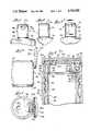
- FIG. 1is a front elevational view showing the closure of the invention affixed to a container body, and with the hinged closure cap in a closed position;
- FIG. 2is a side elevational view of the closure of FIG. 1;
- FIG. 3is a rear elevational view of the closure of FIG. 1;
- FIG. 4is a side elevational view of the closure of the invention, with the hinged cap in a fully opened position;
- FIG. 5is a top plan view of the structure depicted in FIG. 4, and showing the cap hingedly attached to the closure body;
- FIG. 6is an enlarged, vertical cross-sectional view taken substantially on the lines 6--6 of FIG. 3 and showing the mode of securement of the cap to the closure body, in accordance with one embodiment of the invention
- FIG. 7is an enlarged, fragmentary, exploded vertical cross-sectional view showing the intercoupling cooperating snap-in hinge components for pivotally securing the cap to the container-mounted closure body;
- FIG. 8is an enlarged, fragmentary, vertical cross-sectional view showing the cap hingedly secured in place on the closure body, in a partially opened position;
- FIG. 9is a view similar to that shown in FIG. 8, but with the hinged cap in a fully opened position;
- FIG. 10is an exploded, rear elevational view of the closure body and the closure cap, according to the invention, and showing the yoke-mounted, cap-carried hinge shaft;
- FIG. 11is a fragmentary top plan view of the underside of the cap of the closure of the invention, showing the integrally formed hinged shaft fastened thereto;
- FIG. 12is a top plan view of the closure body with the cap removed.
- FIG. 13is an enlarged, vertical cross-sectional view of a second embodiment of the closure of the invention fixed in place on a container and with the hinged cap in a closed position.
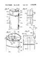
- FIG. 14is a perspective view of an oval container having a closure embodying the principles of the present invention, this embodiment utilizing a three-piece dispenser assembly including an orifice-reducing adapter, a snap-on sleeve or overcap, and a pivotal cap or lid;
- FIG. 15is a side elevational view of the container of FIG. 14, on a somewhat reduced scale
- FIG. 16is an enlarged, fragmentary, prespective view of the container of FIG. 14, with the cap of the closure in a hingedly open position;
- FIG. 17is a fragmentary, side elevational view of the container and closure of FIG. 16 with the cap open, and indicating, in phantom, the neck of the container and a surmounting orifice-reducing adapter;
- FIG. 18is a top plan view of the container of FIG. 17, with the lid in an open mode;
- FIG. 19is a cross-sectional view taken substantially on the lines 19--19 of FIG. 18 and showing the snap-on reducer in place on the container neck and the overcap secured in a groove circumscribing the container;
- FIG. 20is a cross-sectional view taken substantially on the lines 20--20 of FIG. 18 and showing the reducer and the overcap in section;
- FIG. 21is a side elevational view, partly in section, and showing the dispenser cap assembly in a closed disposition
- FIG. 22is an exploded view of the assembly of FIG. 21.
- FIG. 23is a cross-sectional view of the over-cap of the closure assembly of the invention and showing the downwardly projecting hinge legs.
- the aims and objects of the present inventionare achieved by providing a container closure of multi-component construction and securable to the neck of a container for dispensing solid and liquid products.
- the closuresdefine a base which includes a sleeve which embraces and grippingly engages the neck of the container.
- the sleeveitself is surmounted by a bridging top wall formed with a through port for dispensing the contents of the container, and the closure assembly is completed by a hinge-mounted top or lid pivotally supported on the body of the closure.
- the lidcarries, on its underside and projecting therefrom, a plug or boss which telescopically penetrates and seals within the dispensing port of the closure body.
- the cap or lid of the closureis pivotally coupled to the body through a hing assembly in which a cap-carried hinge shaft element seat in cooperating slots, openings or depressions formed in the body of the closure.
- a cap-carried hinge shaft elementseat in cooperating slots, openings or depressions formed in the body of the closure.
- slotsdefining a restricted opening through which a hinge shaft is forcibly urged to seat in a bearing recess at a base of the arms forming the slot. It is an important feature of the invention that the pivotal axis defined by the hinge shaft extends in a plane which parallels the top wall of the sleeve but which is displaced downwardly therefrom.
- An outer, circumscribing wall of the closure bodyis formed with a pair of laterally-spaced, vertically-extending through slits opening upwardly for slidable entry of the arms, extending downwardly from an underside of the cap of the closure and which carry the hinge shaft or hinge shaft elements.
- the arrangement describedfacilitates rotational displacement of the cap through a full arcuate quadrant upon pivotally shifting the cap to a dispensing port exposing orientational mode.
- the structure of the closureprovides an interfering mechanical engagement between the closure cap and the closure body so as effectively and selectively to latch the cap in an open position, thereby insuring unimpaired visibility of the dispensing port and monitoring capability during the product dispensing operation.
- closure of the present inventionis described below for use in conjunction with as a structure secured to a container.
- the container itselfdoes not, per se, constitute an inventive element of the invention, and accordingly, is not described in detail herein.
- FIGS. 1-6there is shown one preferred embodiment of the closure of the invention provided for illustrative purposes and not to be construed in any limiting sense.
- the closure 20is shown as fastened on the neck 24 of a container 30.
- the closure 20 depicted in FIGS. 1-6includes a sleeve 32 defining an outer generally cylindrical wall or skirt 36 formed on its interior surface with threads 40 for intercoupling mating engagement with cooperating threads 44 of the neck 24 of the container 30.
- Surmounting the sleeve-like wall 36 of the closure 20is an integrally formed top wall 50 provided with a through port or orifice 54 through which the material stored in the container 30 is dispensed.
- top wall 50is connected to a downwardly projecting vertical wall 56 terminating in a rearwardly projecting horizontal plate 60 which, in the (FIGS. 7-9) embodiment of the invention depicted, abuts and is integral with the outer wall 36 of the closure at a rear zone 62 of the assembly.
- integrally formed with the plate 60 and projecting upwardly therefromare a pair of laterally-spaced posts 64 each being formed with upwardly opening slots 68 contoured to define a constricted entry 70 and an enlarged bearing-defining recess 72 at the base.
- the opposed, facing jaws 76 and 78have some resiliency, which feature facilitates the assembly of the two-piece closure, the bifurcated posts 64 serving as a lower hinge component, as is more fully described hereinafter.
- the structureis further provided with an annular sealing ring 82 displaced downwardly of the top wall 50 as a terminus of an annular web 86 integrally formed with and projecting generally normally of the top wall 50.
- the sealing ring 82is integrally formed with and defines a downwardly directed projection from the plate 60.
- an outer bounding edge surface 90 of the sealing ring 82abuts and bears upon a facing abutting interior, upwardly presented annular edge 94 of the wall 46 of the neck 24 of the container 30 to provide a positive, resilient seal at the mouth of the container.
- the closure assembly 20includes, as a second distinct component, a lid or cap 100, which in the specific embodiments of the invention illustrated defines a generally planar but slightly vaulted top wall 102 with a circumscribing downwardly directed bounding rim 106.
- the rim 106is integrally formed with a radially inwardly directed annular bead 110 which lockingly invades and seats within a cooperating annular groove 114 formed in an upper sector 116 of the sleeve wall 36.
- the upper sector 116 of the wall 36 of the sleeve 32is displaced radially inwardly so that the rim 106 of the top 100 extends outwardly for ready and convenient digital access insuring that the closure assembly may be conveniently opened without undue effort.
- the top wall 102 of the cap 100 of the closure 20is integrally formed with a generally cylindrical plug 120 projecting downwardly from an underside of the cover 102 and located for registry with for sealing, telescoping penetration into the dispensing port 54 to seal the port during periods of nondelivery of stored contents from the contents.
- the latteris provided at a zone adjacent and overlying the posts 64 of the sleeve unit 32, for functional cooperation with the posts 64, with a yoke assembly 130 which includes a pair of laterally spaced arms 134 fastened to and extending generally downwardly from an undersurface of the top wall 102 of the cover 100 and terminating in a generally horizontally extending hinge shaft 140, the latter being positioned and so sized as to permit forcible insertion thereof through the constricted opening 70 between the jaws 76 and 78 to seat in the recess 72 of the hinge assembly, the arms 134 of the yoke 130 being disposed laterally outwardly of the jaws 76 and 78. (FIGS. 9 and 10).
- the pivotal axis of the hinge assembly of the inventionis substantially below a plane defined by the top wall 50 of the sleeve 32 of the closure 20.
- the rear wall 62 of the sleeve 32is formed with a pair of vertically-extending through slits 150 sized and spaced for lateral correspondence with the arms 134 of the yoke 130 so that upon pivotally shifting the cap 100 to an open position in exposing the dispensing port 54, the arms 134 of the yoke 130 of the top 100 are received in and move downwardly through the slits 150, permitting a full arcuate retraction of the lid 100 from the top wall 50 of the sleeve 32, as depicted in FIG. 9.
- the arrangement describedinsures a completely unimpaired view of the product discharge port 54 during the dis
- the physical arrangement and dimensioning of the component elements of the hinge assemblyare such that in pivoting the cap 100 about the hinge shaft 140 there is established an interfering mechanical engagement between an interior, vertical wall 154 of the sleeve 32 opposite the hinge shaft 140 and the shaft-supporting yoke arms 134 and edge-like projections 156 formed at a lower extremity of the yoke arms 134.
- the projections 156are directed toward and abut and stressingly bear against the wall 154 as the lid 100 is hingedly pivoted on the shaft 140 between closed and open positions of the closure 20.
- a “toggle” effectas the cap 100 is pivoted between a fully closed to a fully opened position.
- the physical structure describedestablishes a detent which prevents the cap from swinging to a closed position or to a position in which viewing of the dispensing port 54 is impaired when the container is tilted to deliver product from the container itself.
- FIG. 13A somewhat modified closure assembly 200 is illustrated in FIG. 13.
- the closureincludes, in addition to a threaded sleeve 204 for threaded engagement with the threaded neck 208 of the container 210, an outer, secondary wall 216 defining a generally cylindrical wall coaxial with the wall 204 and displaced radially outwardly thereof.
- the wall 216which is angled slightly upwardly and inwardly, has an outer diameter at its lower edge 220 which is essentially the same as the outer diameter of the container at its upper shoulder 222 so that the closure wall 216 continues the line of the container in an essentially uninterrupted aesthetic mode.
- the top wall 230is formed with a dispensing port 242
- the lid 250 of the closure 200is formed on the underside of the top wall 254 to extend downwardly therefrom with a plug 256 dimensioned for telescoping entry into the port 242 to seal the port when the lid is in a closed position.
- the second embodiment of the closureis provided with a hinge assembly 260 which in all material respects corresponds to the structure previously described with reference to the first embodiment.
- FIGS. 14 through 23Another embodiment of a closure assembly according to the invention and adapted for use with a non-circular and preferably generally oval container, is shown in FIGS. 14 through 23.
- the product storage and dispensing device 300is shown as including a container 302 having a body or product-storage reservoir 304 of a generally oval cross-sectional configuration and including a floor 306, and opposed arcuately convex front and rear walls 308 and 310 connected to one another by a pair of narrow, coextensive side walls 314 and 316.
- the container body 304is surmounted in sequence, by a frusto-elliptical section 320, a pair of radially inwardly stepped sections 324 and 326 and an open-top annular neck 330.
- the lattercircumscribes a mouth opening 334 in communication with the interior of the container 302.
- the annular section 332constitutes a lip-like wall which is cylindrical on its exterior 336 and is formed interiorly with an outwardly and upward
- an adapter or reducer 348(FIGS. 19 and 20) for effectively reducing the diameter of the neck opening 334 of the container 302.
- the reducer 348is of a firm but resilient plastics material and is structured to snap-lock onto and over the annular wall 332 bounding the mouth at the container neck 330.
- a pair of radially spaced inner and outer walls 352 and 354 extending downwardly from a surmounting horizontal wall-like web 358define therebetween a downwardly open annular moat-like trough 360 in which the lip 332 of the container 302 seats in contiguously nesting, mating engagement.
- the outer annular wall 354 of the reducer 348Adjacent its lower end the outer annular wall 354 of the reducer 348 is integrally formed with a coextensive, radially inwardly directed annular rib 364 which functions as a retainer to hold the adapter in place on the lip-like wall 332 at the neck 330 of the container 302.
- an upwardly projecting annular neck-like web 368Connected to the top wall 358 of the adapter 348 at a position displaced radially inwardly of the inner lower wall 352 is an upwardly projecting annular neck-like web 368 defining an opening or dispensing port 370 of a diameter radially reduced as compared to the open mouth 334 of the container 302 itself.
- a sleeve-like overcap 374has front and rear walls 378 and 380, side walls 384 and 386 congruous with and constituting in-line extension of corresponding walls of the container body 304 of the overcap or sleeve 374.
- the overcap 374is held in place by an annular bead 394 which seats in a groove 396 at the top 398 of the body or reservoir portion 304 of the container 302 as shown in FIG. 19.
- a top wall 402is formed with a circular cutout 404 which is in coaxial registry with the upstanding web 368 of the adapter 348 and into which the web 368 projects, as shown in FIGS. 16 and 19.
- the top wall 402is set back about its periphery to provide a shoulder-like ledge 408 upon which a cover or lid 410 of the container 302 seats.
- the cover 410shaped and dimensioned to have the same perimetric configuration as the container body 302, has a top wall 414 and a circumscribing depending skirt 416 which sleeves over the top wall 402 of the overcap 374, with the lower edge of the skirt 416 seating on the shoulder 408.
- the front wall 378 of the overcap 374is formed with a radially inwardly depressed finger access recess 420 to facilitate one's elevating the lid 410 to an upper mode.
- the lid 410is formed interiorly of the skirt 416 with tabs 422 to retain the cover frictionally secured when closed.
- a pair of laterally spaced hinge arms 430 and 432formed on facing inner lateral sides thereof with horizontally projecting protuberances, bosses or knobs which function as stub-like hinge shafts 436, 438.
- a plug 442Integrally formed with and also projecting downwardly from the underside 426 of the cap 410 is a plug 442 for sealingly penetrating the product dispensing port 370 of the adapter 348 when the lid 410 is in a closed position.
- the top wall 402 of the sleeve 374is formed at a rear marginal zone thereof with a pair of laterally-spaced slots 446 and 448 into which the hinge arms 430 and 432 are received (FIG. 18).
- Walls 452 fastened to and depending from the top wall 402 of the overcap sleeve 374parallel the arms 430 and 432 and are spaced to extend adjacent to for cooperation with the hinge arms 430 and 432, the walls 452 being formed with socket-like recesses or openings 460 into which the diminutive hinge shafts 436 and 438 are hingedly received.
- the overcap 374is also formed with spaced, upwardly opening slits in a rear wall 380 thereof and in line with and communicating with the slots 446, 448 in the top wall 402.
- the structure describedenables one pivotally to swing the cap 410 upwardly through a full quadrant so as to expose the top 402 of the overcap sleeve 374 and the product discharge port 370 to view, thereby to enhance the ease of controlling and metering the quantity of product from the storage reservoir.
- each hinge arm 430is formed at a lower end edge with a projection 432 which abuts and stressingly bears upon an adjacent laterally extending wall section as the cap 410 hingedly pivots on the stub shafts 436 and 438 between open and closed positions. This results in a toggle-like effect to stabilize the cap in selected positions, all in a manner as previously described with reference to the embodiment of the invention illustrated in FIG. 8.
- closure of the present inventionprovides an improved hinging mechanism by means of which the lid is readily pivotal to a fully retracted position with respect to the container top.
- the interference established between the lid and the body of the closureensures that the lid will remain in an open configuration even during the tilting of the container in dispensing product.
- the structure describedalso ensures positive sealing closure of the dispensing orifice and a stabilized registry of articulated components.
Landscapes
- Engineering & Computer Science (AREA)
- Mechanical Engineering (AREA)
- Closures For Containers (AREA)
Abstract
Description
Claims (16)
Priority Applications (1)
| Application Number | Priority Date | Filing Date | Title |
|---|---|---|---|
| US07/061,905US4742928A (en) | 1987-06-11 | 1987-06-11 | Dispensing closure with articulated flip-top cap |
Applications Claiming Priority (1)
| Application Number | Priority Date | Filing Date | Title |
|---|---|---|---|
| US07/061,905US4742928A (en) | 1987-06-11 | 1987-06-11 | Dispensing closure with articulated flip-top cap |
Publications (1)
| Publication Number | Publication Date |
|---|---|
| US4742928Atrue US4742928A (en) | 1988-05-10 |
Family
ID=22038904
Family Applications (1)
| Application Number | Title | Priority Date | Filing Date |
|---|---|---|---|
| US07/061,905Expired - Fee RelatedUS4742928A (en) | 1987-06-11 | 1987-06-11 | Dispensing closure with articulated flip-top cap |
Country Status (1)
| Country | Link |
|---|---|
| US (1) | US4742928A (en) |
Cited By (86)
| Publication number | Priority date | Publication date | Assignee | Title |
|---|---|---|---|---|
| US4887747A (en)* | 1988-06-08 | 1989-12-19 | Seaquist Closures, A Division Of Pittway Corporation | Two-piece, snap-action closure |
| USD317869S (en) | 1989-04-20 | 1991-07-02 | Chesebrough-Pond's Inc. | Bottle cap |
| USD318012S (en) | 1989-04-17 | 1991-07-09 | Chesebrough-Pond's USA Co. (division of Conopco, Inc.) | Combined bottle and cap |
| USD318231S (en) | 1988-11-02 | 1991-07-16 | The Pittway Corporation | Closure for dispensing container |
| USD318425S (en) | 1989-04-17 | 1991-07-23 | Chesebrough-Pond's USA Co. (division of Conopco, Inc.) | Combined bottle and cap |
| USD318424S (en) | 1989-04-17 | 1991-07-23 | Chesebrough-Pond's USA Co. (division of Conopco, Inc.) | Combined bottle and cap |
| USD318423S (en) | 1988-11-01 | 1991-07-23 | Chesebrough-Pond's USA Co. (division of Conopco, Inc.) | Combined bottle and cap |
| USD318619S (en) | 1989-04-17 | 1991-07-30 | Chesebrough-Pond's USA Co. (division of Conopco, Inc.) | Combined bottle and cap |
| USD318620S (en) | 1989-04-17 | 1991-07-30 | Chesebrough-Pond's USA Co. (Conopco, Inc.) | Combined bottle and cap |
| USD318801S (en) | 1989-04-17 | 1991-08-06 | Chesebrough-Pond's USA Co. (division of Conopco, Inc.) | Combined bottle and cap |
| USD319013S (en) | 1989-04-17 | 1991-08-13 | Chesebrough-Pond's U.S.A. Co. (division of Conopco, Inc.) | Combined bottle and cap |
| US5038957A (en)* | 1990-02-23 | 1991-08-13 | Seaquist Closures, A Division Of Pittway Corporation | Two-piece, snap-action closure with body deck spring panel |
| USD319012S (en) | 1989-04-17 | 1991-08-13 | Chesebrough-Pond's U.S.A. Co. (Conopco, Inc.) | Combined bottle and cap |
| USD319391S (en) | 1989-04-17 | 1991-08-27 | Chesebrough-Pond's USA Co. (division of Conopco, Inc.) | Combined bottle and cap |
| US5065887A (en)* | 1990-02-20 | 1991-11-19 | Scott Paper Company | Container with hinged cover |
| US5065911A (en)* | 1990-05-14 | 1991-11-19 | Seaquist Closures | Two-piece dispensing closure with cantilevered biasing member |
| USD322756S (en) | 1989-04-17 | 1991-12-31 | Chesebrough-Pond's USA Co. (division of Conopco, Inc.) | Combined bottle and cap |
| US5108029A (en)* | 1990-02-16 | 1992-04-28 | Capitol Spouts, Inc. | Reclosable attachment for containers |
| USD328710S (en) | 1990-08-23 | 1992-08-18 | The Procter & Gamble Company | Dispensing bottle |
| EP0455916A3 (en)* | 1990-05-03 | 1992-12-02 | Nalge Company | Dropper bottle assembly |
| US5246145A (en)* | 1990-05-03 | 1993-09-21 | Nalge Company | Liquid dropper spout having lockable pivoted closure cap |
| US5248056A (en)* | 1992-04-15 | 1993-09-28 | Eastman Kodak Company | Disposable reservoir |
| US5251793A (en)* | 1988-07-01 | 1993-10-12 | Bolen Robert J | Dispensing closure |
| US5328058A (en)* | 1990-05-03 | 1994-07-12 | Nalge Company | Dropper bottle assembly with squeeze cap |
| USD349650S (en) | 1992-08-20 | 1994-08-16 | Johnson & Johnson Consumer Products, Inc. | Bottle cap |
| USD349857S (en) | 1992-08-20 | 1994-08-23 | Johnson & Johnson Consumer Products, Inc. | Combined bottle and cap |
| USD352663S (en) | 1992-10-02 | 1994-11-22 | Lever Brothers Company, Division Of Conopco, Inc. | Bottle with cap |
| US5381935A (en)* | 1991-12-12 | 1995-01-17 | Tetra Laval Holdings & Finance S.A. | Closure unit for a container having a hinged construction, made of different materials and having a film which tears on first opening |
| US5395015A (en)* | 1988-07-01 | 1995-03-07 | Bolen, Jr.; Robert J. | Dispensing closure with a modified lid for increased opening angle |
| US5398837A (en)* | 1993-02-15 | 1995-03-21 | Degrassi; Alberto | Cell culture flask and closure |
| USD357418S (en) | 1992-08-20 | 1995-04-18 | Johnson & Johnson Consumer Products, Inc. | Combined bottle and cap |
| USD362626S (en) | 1994-02-14 | 1995-09-26 | Chesebrough-Pond's Usa Co., Division Of Conopco, Inc. | Container with cap |
| EP0597946A4 (en)* | 1991-08-12 | 1996-08-21 | Zeller Plastic Inc | SINGLE WALL DISPENSER LOCK WITH POSITIVE FINDING DEVICES. |
| AU671819B2 (en)* | 1992-02-07 | 1996-09-12 | Polytop Corporation | Flexible holder for "living" hinge joining lid to closure body of dispensing closure |
| US5636740A (en)* | 1994-04-18 | 1997-06-10 | Ncm International, Inc. | Multi-element decorative dispensing closure |
| USD382206S (en)* | 1995-05-24 | 1997-08-12 | John Charles Worthington | Combined bottle and closure |
| USD397038S (en) | 1997-10-14 | 1998-08-18 | Para Laboratories, Inc. | Combined bottle and cap for styling gel |
| USD419864S (en)* | 1998-12-29 | 2000-02-01 | G K Packaging, Inc. | Combined bottle and cap |
| US6039197A (en)* | 1996-06-24 | 2000-03-21 | Kenall Manufacturing Co. | Method and apparatus for securing the same hinged lid assembly to each of a plurality of different containers |
| USD424448S (en)* | 1999-08-13 | 2000-05-09 | Heinz Weber | Combined container and cap |
| USD429629S (en) | 1999-03-04 | 2000-08-22 | G K Packaging, Inc. | Combined bottle and cap |
| USD433932S (en)* | 1999-12-21 | 2000-11-21 | G K Packaging, Inc. | Combined bottle and cap |
| USD434659S (en)* | 1995-11-08 | 2000-12-05 | Johnson & Johnson Consumer Products, Inc. | Bottle cap |
| US6263543B1 (en)* | 1999-07-30 | 2001-07-24 | Avaya Technology Corp. | Self-latching hinge design |
| US20030010787A1 (en)* | 2001-06-04 | 2003-01-16 | The Procter & Gamble Company | Container, method, and apparatus to provide fresher packed coffee |
| USD474408S1 (en) | 2001-10-30 | 2003-05-13 | Qualipac | Combined bottle and cap for cosmetic use |
| US6631833B2 (en) | 2001-02-16 | 2003-10-14 | Ccl Container Corporation | Oval-shaped tube closure |
| USD486400S1 (en) | 2001-12-04 | 2004-02-10 | Db Design Gmbh | Bottle |
| US6837407B1 (en)* | 2002-11-25 | 2005-01-04 | Christopher R Towers | Storage container intended for placement into standard water bottle holders often found on bicycles |
| USD504613S1 (en) | 2002-07-19 | 2005-05-03 | Pichiney Plastic Packaging, Inc. | Cap for a tubular dispenser |
| USD504611S1 (en)* | 2003-04-17 | 2005-05-03 | Db Design Gmbh | Oval fliptop for a bottle |
| USD507185S1 (en)* | 2003-05-29 | 2005-07-12 | Plastic Bottle Corporation | Bottle |
| US20050274687A1 (en)* | 2004-06-14 | 2005-12-15 | Mccutchan Michael D | Package comprising shrink label for personal care products |
| US20060115385A1 (en)* | 2004-12-01 | 2006-06-01 | Meridian Bioscience, Inc. | Specimen collection system |
| USD522867S1 (en)* | 2003-11-27 | 2006-06-13 | Db Design Gmbh | Bottle |
| USD525135S1 (en)* | 2004-04-27 | 2006-07-18 | Db Design Gmbh | Cosmetic container |
| US20060191948A1 (en)* | 2005-01-25 | 2006-08-31 | Seaquist Closures Foreign, Inc. | Closure with lid having an opening resistance |
| USD527636S1 (en)* | 2004-05-21 | 2006-09-05 | Db Design Gmbh | Cosmetic container |
| USD527644S1 (en)* | 2004-04-27 | 2006-09-05 | Db Design Gmbh | Cosmetic container |
| USD531040S1 (en)* | 2004-09-08 | 2006-10-31 | Guess?, Inc. | Cosmetics bottle |
| USD533453S1 (en) | 2002-07-19 | 2006-12-12 | Francis John Lovell | Cap for a tubular dispenser |
| US20070017939A1 (en)* | 2005-07-22 | 2007-01-25 | Conroy Leslee A | Directional pour spout container cap |
| US20080083758A1 (en)* | 2006-06-12 | 2008-04-10 | Kraft Foods Holdings, Inc. | Push button flip top with attached second container |
| EP1392595A4 (en)* | 2001-05-30 | 2008-05-07 | Seaquist Closures Foreign Inc | Single axis dual dispensing closure |
| US20080289984A1 (en)* | 2007-04-18 | 2008-11-27 | Raven Sophie R | Container for an automatic injector |
| US20090049648A1 (en)* | 2007-08-24 | 2009-02-26 | Williams Douglas E | Hinge for an enclosure |
| US7510095B2 (en) | 2005-03-11 | 2009-03-31 | Berry Plastics Corporation | System comprising a radially aligned container and closure |
| EP1427644A4 (en)* | 2001-08-17 | 2009-06-03 | Seaquist Closures Foreign Inc | Tamper-evident closure |
| US20090232947A1 (en)* | 2008-03-14 | 2009-09-17 | Gerard Laurent Buisson | Packaging system to provide fresh packed coffee |
| JP2009545497A (en)* | 2006-08-04 | 2009-12-24 | エムアールピー メディカル リサーチ アンド プロモーション エスタブリッシュメント | Bottles for storing liquids, especially pharmaceutical products |
| USD614494S1 (en)* | 2009-01-29 | 2010-04-27 | Johnson & Johnson Consumer Companies, Inc. | Package |
| WO2010133654A1 (en) | 2009-05-20 | 2010-11-25 | Nestec S.A. | Dispensing cap |
| EP2532601A1 (en)* | 2011-06-08 | 2012-12-12 | Thermos L.L.C. | Drink bottle and lid with cover for drink spout |
| WO2013010934A1 (en) | 2011-07-21 | 2013-01-24 | Nestec S.A. | Cup or mug cover |
| US8689989B2 (en) | 2012-02-28 | 2014-04-08 | Thermos L.L.C. | Drink bottle and lid with button release at back of lid |
| US20140190993A1 (en)* | 2011-07-21 | 2014-07-10 | Colgate-Palmolive Company | System of containers having interchangeable components and method of manufacturing the same |
| USD725966S1 (en) | 2013-05-20 | 2015-04-07 | Thermos L.L.C. | Combined drink bottle and lid |
| US20150238030A1 (en)* | 2014-02-27 | 2015-08-27 | Craig E. Brown | Leakproof Cover for Combined Pouring and Venting Container Closure |
| US9150335B2 (en) | 2012-02-28 | 2015-10-06 | Thermos L.L.C. | Beverage container system with button release for lid |
| US9724629B2 (en) | 2013-05-20 | 2017-08-08 | Thermos L.L.C. | Bottle system and method for filtering or treating a beverage |
| USD813049S1 (en)* | 2016-04-27 | 2018-03-20 | The Boots Company Plc | Bottle with cap |
| WO2021055066A1 (en)* | 2019-09-18 | 2021-03-25 | Silgan White Cap LLC | Tamper evident flip cap |
| USD935276S1 (en) | 2018-08-20 | 2021-11-09 | Thermos L.L.C. | Beverage bottle with lid |
| CN114787045A (en)* | 2020-03-24 | 2022-07-22 | 赫斯基注塑系统有限公司 | Closure device for a container |
| EP4214135A4 (en)* | 2020-09-15 | 2024-10-23 | ELC Management LLC | Container-closure system |
| US20240391660A1 (en)* | 2023-05-25 | 2024-11-28 | Sarah J. Purdy | Bottle Cap Drip Tray Device |
Citations (7)
| Publication number | Priority date | Publication date | Assignee | Title |
|---|---|---|---|---|
| US4377247A (en)* | 1978-10-31 | 1983-03-22 | Polytop Corporation | Dispensing closure employing living hinge |
| US4399928A (en)* | 1982-04-14 | 1983-08-23 | Janler Corporation | Closure cap |
| US4402435A (en)* | 1981-05-15 | 1983-09-06 | Libit Sidney M | Dispensing type cap closure |
| US4441637A (en)* | 1981-05-15 | 1984-04-10 | Libit Sidney M | Dispensing type cap closure |
| US4625898A (en)* | 1984-09-11 | 1986-12-02 | Polytop Corporation | Dispensing closure employing living hinge with cams to momentarily deform hinge and recesses to accept cams |
| US4632266A (en)* | 1986-02-24 | 1986-12-30 | Otto Osswald | Container cap |
| US4699301A (en)* | 1985-10-25 | 1987-10-13 | Blake William S | Two piece dispensing closure |
- 1987
- 1987-06-11USUS07/061,905patent/US4742928A/ennot_activeExpired - Fee Related
Patent Citations (7)
| Publication number | Priority date | Publication date | Assignee | Title |
|---|---|---|---|---|
| US4377247A (en)* | 1978-10-31 | 1983-03-22 | Polytop Corporation | Dispensing closure employing living hinge |
| US4402435A (en)* | 1981-05-15 | 1983-09-06 | Libit Sidney M | Dispensing type cap closure |
| US4441637A (en)* | 1981-05-15 | 1984-04-10 | Libit Sidney M | Dispensing type cap closure |
| US4399928A (en)* | 1982-04-14 | 1983-08-23 | Janler Corporation | Closure cap |
| US4625898A (en)* | 1984-09-11 | 1986-12-02 | Polytop Corporation | Dispensing closure employing living hinge with cams to momentarily deform hinge and recesses to accept cams |
| US4699301A (en)* | 1985-10-25 | 1987-10-13 | Blake William S | Two piece dispensing closure |
| US4632266A (en)* | 1986-02-24 | 1986-12-30 | Otto Osswald | Container cap |
Cited By (103)
| Publication number | Priority date | Publication date | Assignee | Title |
|---|---|---|---|---|
| US4887747A (en)* | 1988-06-08 | 1989-12-19 | Seaquist Closures, A Division Of Pittway Corporation | Two-piece, snap-action closure |
| US5251793A (en)* | 1988-07-01 | 1993-10-12 | Bolen Robert J | Dispensing closure |
| US5395015A (en)* | 1988-07-01 | 1995-03-07 | Bolen, Jr.; Robert J. | Dispensing closure with a modified lid for increased opening angle |
| USD318423S (en) | 1988-11-01 | 1991-07-23 | Chesebrough-Pond's USA Co. (division of Conopco, Inc.) | Combined bottle and cap |
| USD318231S (en) | 1988-11-02 | 1991-07-16 | The Pittway Corporation | Closure for dispensing container |
| USD318620S (en) | 1989-04-17 | 1991-07-30 | Chesebrough-Pond's USA Co. (Conopco, Inc.) | Combined bottle and cap |
| USD318424S (en) | 1989-04-17 | 1991-07-23 | Chesebrough-Pond's USA Co. (division of Conopco, Inc.) | Combined bottle and cap |
| USD318619S (en) | 1989-04-17 | 1991-07-30 | Chesebrough-Pond's USA Co. (division of Conopco, Inc.) | Combined bottle and cap |
| USD318801S (en) | 1989-04-17 | 1991-08-06 | Chesebrough-Pond's USA Co. (division of Conopco, Inc.) | Combined bottle and cap |
| USD319013S (en) | 1989-04-17 | 1991-08-13 | Chesebrough-Pond's U.S.A. Co. (division of Conopco, Inc.) | Combined bottle and cap |
| USD318425S (en) | 1989-04-17 | 1991-07-23 | Chesebrough-Pond's USA Co. (division of Conopco, Inc.) | Combined bottle and cap |
| USD319012S (en) | 1989-04-17 | 1991-08-13 | Chesebrough-Pond's U.S.A. Co. (Conopco, Inc.) | Combined bottle and cap |
| USD319391S (en) | 1989-04-17 | 1991-08-27 | Chesebrough-Pond's USA Co. (division of Conopco, Inc.) | Combined bottle and cap |
| USD318012S (en) | 1989-04-17 | 1991-07-09 | Chesebrough-Pond's USA Co. (division of Conopco, Inc.) | Combined bottle and cap |
| USD322756S (en) | 1989-04-17 | 1991-12-31 | Chesebrough-Pond's USA Co. (division of Conopco, Inc.) | Combined bottle and cap |
| USD317869S (en) | 1989-04-20 | 1991-07-02 | Chesebrough-Pond's Inc. | Bottle cap |
| US5108029A (en)* | 1990-02-16 | 1992-04-28 | Capitol Spouts, Inc. | Reclosable attachment for containers |
| US5065887A (en)* | 1990-02-20 | 1991-11-19 | Scott Paper Company | Container with hinged cover |
| US5038957A (en)* | 1990-02-23 | 1991-08-13 | Seaquist Closures, A Division Of Pittway Corporation | Two-piece, snap-action closure with body deck spring panel |
| EP0455916A3 (en)* | 1990-05-03 | 1992-12-02 | Nalge Company | Dropper bottle assembly |
| US5246145A (en)* | 1990-05-03 | 1993-09-21 | Nalge Company | Liquid dropper spout having lockable pivoted closure cap |
| US5328058A (en)* | 1990-05-03 | 1994-07-12 | Nalge Company | Dropper bottle assembly with squeeze cap |
| US5065911A (en)* | 1990-05-14 | 1991-11-19 | Seaquist Closures | Two-piece dispensing closure with cantilevered biasing member |
| USD328710S (en) | 1990-08-23 | 1992-08-18 | The Procter & Gamble Company | Dispensing bottle |
| EP0597946A4 (en)* | 1991-08-12 | 1996-08-21 | Zeller Plastic Inc | SINGLE WALL DISPENSER LOCK WITH POSITIVE FINDING DEVICES. |
| US5381935A (en)* | 1991-12-12 | 1995-01-17 | Tetra Laval Holdings & Finance S.A. | Closure unit for a container having a hinged construction, made of different materials and having a film which tears on first opening |
| AU671819B2 (en)* | 1992-02-07 | 1996-09-12 | Polytop Corporation | Flexible holder for "living" hinge joining lid to closure body of dispensing closure |
| US5248056A (en)* | 1992-04-15 | 1993-09-28 | Eastman Kodak Company | Disposable reservoir |
| USD349857S (en) | 1992-08-20 | 1994-08-23 | Johnson & Johnson Consumer Products, Inc. | Combined bottle and cap |
| USD357418S (en) | 1992-08-20 | 1995-04-18 | Johnson & Johnson Consumer Products, Inc. | Combined bottle and cap |
| USD349650S (en) | 1992-08-20 | 1994-08-16 | Johnson & Johnson Consumer Products, Inc. | Bottle cap |
| USD352663S (en) | 1992-10-02 | 1994-11-22 | Lever Brothers Company, Division Of Conopco, Inc. | Bottle with cap |
| US5398837A (en)* | 1993-02-15 | 1995-03-21 | Degrassi; Alberto | Cell culture flask and closure |
| USD362626S (en) | 1994-02-14 | 1995-09-26 | Chesebrough-Pond's Usa Co., Division Of Conopco, Inc. | Container with cap |
| US5636740A (en)* | 1994-04-18 | 1997-06-10 | Ncm International, Inc. | Multi-element decorative dispensing closure |
| USD382206S (en)* | 1995-05-24 | 1997-08-12 | John Charles Worthington | Combined bottle and closure |
| USD434659S (en)* | 1995-11-08 | 2000-12-05 | Johnson & Johnson Consumer Products, Inc. | Bottle cap |
| US6039197A (en)* | 1996-06-24 | 2000-03-21 | Kenall Manufacturing Co. | Method and apparatus for securing the same hinged lid assembly to each of a plurality of different containers |
| USD397038S (en) | 1997-10-14 | 1998-08-18 | Para Laboratories, Inc. | Combined bottle and cap for styling gel |
| USD419864S (en)* | 1998-12-29 | 2000-02-01 | G K Packaging, Inc. | Combined bottle and cap |
| USD429629S (en) | 1999-03-04 | 2000-08-22 | G K Packaging, Inc. | Combined bottle and cap |
| US6263543B1 (en)* | 1999-07-30 | 2001-07-24 | Avaya Technology Corp. | Self-latching hinge design |
| USD424448S (en)* | 1999-08-13 | 2000-05-09 | Heinz Weber | Combined container and cap |
| USD433932S (en)* | 1999-12-21 | 2000-11-21 | G K Packaging, Inc. | Combined bottle and cap |
| US6631833B2 (en) | 2001-02-16 | 2003-10-14 | Ccl Container Corporation | Oval-shaped tube closure |
| US20040031814A1 (en)* | 2001-02-16 | 2004-02-19 | Harriman Ron E. | Oval-shaped tube closure |
| US6932240B2 (en) | 2001-02-16 | 2005-08-23 | Ccl Container Corporation | Oval-shaped tube closure |
| EP1392595A4 (en)* | 2001-05-30 | 2008-05-07 | Seaquist Closures Foreign Inc | Single axis dual dispensing closure |
| US20030010787A1 (en)* | 2001-06-04 | 2003-01-16 | The Procter & Gamble Company | Container, method, and apparatus to provide fresher packed coffee |
| US7169418B2 (en) | 2001-06-04 | 2007-01-30 | The Procter And Gamble Company | Packaging system to provide fresh packed coffee |
| EP1427644A4 (en)* | 2001-08-17 | 2009-06-03 | Seaquist Closures Foreign Inc | Tamper-evident closure |
| USD474408S1 (en) | 2001-10-30 | 2003-05-13 | Qualipac | Combined bottle and cap for cosmetic use |
| USD489267S1 (en) | 2001-10-30 | 2004-05-04 | Qualipac | Combined bottle and cap for cosmetic use |
| USD486400S1 (en) | 2001-12-04 | 2004-02-10 | Db Design Gmbh | Bottle |
| USD504613S1 (en) | 2002-07-19 | 2005-05-03 | Pichiney Plastic Packaging, Inc. | Cap for a tubular dispenser |
| USD533453S1 (en) | 2002-07-19 | 2006-12-12 | Francis John Lovell | Cap for a tubular dispenser |
| USD520873S1 (en) | 2002-07-19 | 2006-05-16 | Pechiney Plastic Packaging, Inc. | Cap for a tubular dispenser |
| US6837407B1 (en)* | 2002-11-25 | 2005-01-04 | Christopher R Towers | Storage container intended for placement into standard water bottle holders often found on bicycles |
| USD504611S1 (en)* | 2003-04-17 | 2005-05-03 | Db Design Gmbh | Oval fliptop for a bottle |
| USD507185S1 (en)* | 2003-05-29 | 2005-07-12 | Plastic Bottle Corporation | Bottle |
| USD522867S1 (en)* | 2003-11-27 | 2006-06-13 | Db Design Gmbh | Bottle |
| USD527644S1 (en)* | 2004-04-27 | 2006-09-05 | Db Design Gmbh | Cosmetic container |
| USD529388S1 (en)* | 2004-04-27 | 2006-10-03 | Db Design, Gmbh | Cosmetic container |
| USD525135S1 (en)* | 2004-04-27 | 2006-07-18 | Db Design Gmbh | Cosmetic container |
| USD527636S1 (en)* | 2004-05-21 | 2006-09-05 | Db Design Gmbh | Cosmetic container |
| US20050274687A1 (en)* | 2004-06-14 | 2005-12-15 | Mccutchan Michael D | Package comprising shrink label for personal care products |
| USD531040S1 (en)* | 2004-09-08 | 2006-10-31 | Guess?, Inc. | Cosmetics bottle |
| US7648681B2 (en) | 2004-12-01 | 2010-01-19 | Meridian Bioscience, Inc. | Specimen collection system |
| US20060115385A1 (en)* | 2004-12-01 | 2006-06-01 | Meridian Bioscience, Inc. | Specimen collection system |
| US20060191948A1 (en)* | 2005-01-25 | 2006-08-31 | Seaquist Closures Foreign, Inc. | Closure with lid having an opening resistance |
| US7510095B2 (en) | 2005-03-11 | 2009-03-31 | Berry Plastics Corporation | System comprising a radially aligned container and closure |
| US7549559B2 (en)* | 2005-07-22 | 2009-06-23 | Conroy Foods, Inc. | Directional pour spout container cap |
| US20070017939A1 (en)* | 2005-07-22 | 2007-01-25 | Conroy Leslee A | Directional pour spout container cap |
| US20080083758A1 (en)* | 2006-06-12 | 2008-04-10 | Kraft Foods Holdings, Inc. | Push button flip top with attached second container |
| US20090321479A1 (en)* | 2006-08-04 | 2009-12-31 | Antonio Fontana | Bottle for containing fluids, particularly for pharmaceutical products or the like |
| US8408433B2 (en)* | 2006-08-04 | 2013-04-02 | Mrp Medical Research & Promotion Establishment | Bottle for containing fluids, particularly for pharmaceutical products or the like |
| JP2009545497A (en)* | 2006-08-04 | 2009-12-24 | エムアールピー メディカル リサーチ アンド プロモーション エスタブリッシュメント | Bottles for storing liquids, especially pharmaceutical products |
| US20080289984A1 (en)* | 2007-04-18 | 2008-11-27 | Raven Sophie R | Container for an automatic injector |
| US20090049648A1 (en)* | 2007-08-24 | 2009-02-26 | Williams Douglas E | Hinge for an enclosure |
| US20090232947A1 (en)* | 2008-03-14 | 2009-09-17 | Gerard Laurent Buisson | Packaging system to provide fresh packed coffee |
| USD614494S1 (en)* | 2009-01-29 | 2010-04-27 | Johnson & Johnson Consumer Companies, Inc. | Package |
| WO2010133654A1 (en) | 2009-05-20 | 2010-11-25 | Nestec S.A. | Dispensing cap |
| EP2532601A1 (en)* | 2011-06-08 | 2012-12-12 | Thermos L.L.C. | Drink bottle and lid with cover for drink spout |
| US8550269B2 (en) | 2011-06-08 | 2013-10-08 | Thermos L.L.C. | Drink bottle and lid with cover for drink spout |
| EP2799361A1 (en)* | 2011-06-08 | 2014-11-05 | Thermos L.L.C. | Drink bottle lid with cover |
| WO2013010934A1 (en) | 2011-07-21 | 2013-01-24 | Nestec S.A. | Cup or mug cover |
| US20140190993A1 (en)* | 2011-07-21 | 2014-07-10 | Colgate-Palmolive Company | System of containers having interchangeable components and method of manufacturing the same |
| US8689989B2 (en) | 2012-02-28 | 2014-04-08 | Thermos L.L.C. | Drink bottle and lid with button release at back of lid |
| US9150335B2 (en) | 2012-02-28 | 2015-10-06 | Thermos L.L.C. | Beverage container system with button release for lid |
| USD725966S1 (en) | 2013-05-20 | 2015-04-07 | Thermos L.L.C. | Combined drink bottle and lid |
| US9724629B2 (en) | 2013-05-20 | 2017-08-08 | Thermos L.L.C. | Bottle system and method for filtering or treating a beverage |
| US9445677B2 (en)* | 2014-02-27 | 2016-09-20 | New Vent Designs, Inc. | Leakproof cover for combined pouring and venting container closure |
| US20150238030A1 (en)* | 2014-02-27 | 2015-08-27 | Craig E. Brown | Leakproof Cover for Combined Pouring and Venting Container Closure |
| USD813049S1 (en)* | 2016-04-27 | 2018-03-20 | The Boots Company Plc | Bottle with cap |
| USD935276S1 (en) | 2018-08-20 | 2021-11-09 | Thermos L.L.C. | Beverage bottle with lid |
| WO2021055066A1 (en)* | 2019-09-18 | 2021-03-25 | Silgan White Cap LLC | Tamper evident flip cap |
| US11214414B2 (en) | 2019-09-18 | 2022-01-04 | Silgan White Cap LLC | Tamper evident flip cap |
| US11827425B2 (en) | 2019-09-18 | 2023-11-28 | Silgan White Cap LLC | Tamper evident flip cap |
| CN114787045A (en)* | 2020-03-24 | 2022-07-22 | 赫斯基注塑系统有限公司 | Closure device for a container |
| CN114787045B (en)* | 2020-03-24 | 2024-05-14 | 赫斯基注塑系统有限公司 | Closure device for a container |
| EP4214135A4 (en)* | 2020-09-15 | 2024-10-23 | ELC Management LLC | Container-closure system |
| US20240391660A1 (en)* | 2023-05-25 | 2024-11-28 | Sarah J. Purdy | Bottle Cap Drip Tray Device |
| US12195243B2 (en)* | 2023-05-25 | 2025-01-14 | Sarah J. Purdy | Bottle cap drip tray device |
Similar Documents
| Publication | Publication Date | Title |
|---|---|---|
| US4742928A (en) | Dispensing closure with articulated flip-top cap | |
| US4903870A (en) | Dispensing closure | |
| US5236107A (en) | Dispensing cap construction | |
| US5542585A (en) | Dispensing closure with pivotably mounted spout and means for limiting travel thereof | |
| US4241855A (en) | Flow controlling pouring spout | |
| CA2278078C (en) | Hinged cap and cap body | |
| US8474646B2 (en) | Closure having a drip minimizing lid | |
| US5395015A (en) | Dispensing closure with a modified lid for increased opening angle | |
| EP1027851B1 (en) | Container with dispensing assembly | |
| US5221017A (en) | Controlled dropper tip closure | |
| US5267675A (en) | Pouring devices for viscous liquid such as paint | |
| US4047648A (en) | Spout with snap acting cover and drain hole | |
| US5251793A (en) | Dispensing closure | |
| US5022566A (en) | Press-open side dispensing closure | |
| US4832219A (en) | Dual dispensing hinged closure | |
| HU222617B1 (en) | Condiment-cellar | |
| JPH05147667A (en) | Stir lid device for paint | |
| KR100314367B1 (en) | Condiment Dispenser | |
| US6095374A (en) | Closure for supporting a container of viscous liquid | |
| EP0701523B1 (en) | Clog-resistant toggle disk closure | |
| US5358154A (en) | One-hand-operable container closure | |
| US4807781A (en) | Container and dispensing-closure assembly | |
| US5246150A (en) | Pivoting dispensing closure | |
| US4177904A (en) | Seal assembly for bottles or flasks | |
| US2104744A (en) | Pouring spout container |
Legal Events
| Date | Code | Title | Description |
|---|---|---|---|
| AS | Assignment | Owner name:W. BRAUN COMPANY, 300 NORTH CANAL STREET, CHICAGO, Free format text:ASSIGNMENT OF ASSIGNORS INTEREST.;ASSIGNOR:BRAUN, MORRIS;REEL/FRAME:004758/0258 Effective date:19870422 | |
| FPAY | Fee payment | Year of fee payment:4 | |
| REMI | Maintenance fee reminder mailed | ||
| FPAY | Fee payment | Year of fee payment:8 | |
| SULP | Surcharge for late payment | ||
| AS | Assignment | Owner name:GENERAL ELECTRIC CAPITAL CORPORATION, AS AGENT, IL Free format text:SECURITY INTEREST;ASSIGNOR:W. BRAUN COMPANY;REEL/FRAME:009342/0103 Effective date:19980626 | |
| AS | Assignment | Owner name:W. BRAUN COMPANY, L.L.C., MISSOURI Free format text:MERGER;ASSIGNOR:W. BRAUN COMPANY, A CORP. OF DE;REEL/FRAME:009678/0739 Effective date:19981230 | |
| AS | Assignment | Owner name:KRANSON INDUSTRIES, INC., A CORP. OF MISSOURI, MIS Free format text:ASSIGNMENT OF ASSIGNORS INTEREST;ASSIGNOR:W. BRAUM COMPANY, L.L.C., A DELAWARE LIMITED LIABILITY COMPANY;REEL/FRAME:009689/0478 Effective date:19981230 | |
| AS | Assignment | Owner name:GENERAL ELECTRIC CAPITAL CORPORATION, AS AGENT, IL Free format text:AMENDMENT NO. 2 TO PATENT SECURITY AGREEMENT;ASSIGNOR:KRANSON INDUSTRIES, INC.;REEL/FRAME:009711/0119 Effective date:19981230 | |
| AS | Assignment | Owner name:W. BRAUN COMPANY, MISSOURI Free format text:TERMINATION OF SECURITY INTERST;ASSIGNOR:GENERAL ELECTRIC CAPITAL CORPORATION;REEL/FRAME:010321/0653 Effective date:19991101 Owner name:KRANSON INDUSTRIES, INC., MISSOURI Free format text:TERMINATION OF SECURITY INTEREST;ASSIGNOR:GENERAL ELECTRIC CAPITAL CORPORATION;REEL/FRAME:010321/0781 Effective date:19991101 | |
| REMI | Maintenance fee reminder mailed | ||
| AS | Assignment | Owner name:LATHAM & WATKINS, ILLINOIS Free format text:SECURITY INTEREST;ASSIGNOR:KRANSON INDUSTRIES, INC.;REEL/FRAME:010567/0281 Effective date:19991029 | |
| LAPS | Lapse for failure to pay maintenance fees | ||
| FP | Lapsed due to failure to pay maintenance fee | Effective date:20000510 | |
| AS | Assignment | Owner name:ANTARES CAPITAL CORPORATION, AS AGENT, ILLINOIS Free format text:CORRECTIVE ASSIGNMENT TO CORRECT THE RECEIVING PARTY INFORMATION- SHOULD READ ANTARES CAPITAL CORPORATION, AS AGENT PREVIOUSLY RECORDED ON REEL 010567 FRAME 0281;ASSIGNOR:KRANSON INDUSTRIES, INC.;REEL/FRAME:017996/0688 Effective date:19991029 | |
| AS | Assignment | Owner name:KRANSON INDUSTRIES, INC., MISSOURI Free format text:RELEASE BY SECURED PARTY;ASSIGNOR:ANTARES CAPITAL CORPORATION, AS AGENT;REEL/FRAME:018039/0310 Effective date:20060726 | |
| AS | Assignment | Owner name:KRANSON INDUSTRIES, INC., MISSOURI Free format text:RELEASE BY SECURED PARTY;ASSIGNOR:ANTARES CAPITAL CORPORATION, AS AGENT;REEL/FRAME:018746/0570 Effective date:20060726 | |
| AS | Assignment | Owner name:GENERAL ELECTRIC CAPITAL CORPORATION, AS AGENT, IL Free format text:SECURITY AGREEMENT;ASSIGNOR:TRICORBRAUN INC.;REEL/FRAME:026468/0909 Effective date:20110616 | |
| AS | Assignment | Owner name:ANTARES CAPITAL LP, ILLINOIS Free format text:ASSIGNMENT OF INTELLECTUAL PROPERTY SECURITY AGREEMENT;ASSIGNOR:GENERAL ELECTRIC CAPITAL CORPORATION;REEL/FRAME:036527/0954 Effective date:20150821 | |
| AS | Assignment | Owner name:TRICORBRAUN, INC., MISSOURI Free format text:RELEASE BY SECURED PARTY;ASSIGNOR:GENERAL ELECTRIC COMPANY;REEL/FRAME:040467/0492 Effective date:20161130 | |
| STCH | Information on status: patent discontinuation | Free format text:PATENT EXPIRED DUE TO NONPAYMENT OF MAINTENANCE FEES UNDER 37 CFR 1.362 |