US4741684A - Optical cable with filling compound and parallel fibers - Google Patents
Optical cable with filling compound and parallel fibersDownload PDFInfo
- Publication number
- US4741684A US4741684AUS07/012,754US1275487AUS4741684AUS 4741684 AUS4741684 AUS 4741684AUS 1275487 AUS1275487 AUS 1275487AUS 4741684 AUS4741684 AUS 4741684A
- Authority
- US
- United States
- Prior art keywords
- fibers
- optical fibers
- capstan
- tube
- buffer tube
- Prior art date
- Legal status (The legal status is an assumption and is not a legal conclusion. Google has not performed a legal analysis and makes no representation as to the accuracy of the status listed.)
- Expired - Lifetime
Links
Images


Classifications
- G—PHYSICS
- G02—OPTICS
- G02B—OPTICAL ELEMENTS, SYSTEMS OR APPARATUS
- G02B6/00—Light guides; Structural details of arrangements comprising light guides and other optical elements, e.g. couplings
- G02B6/44—Mechanical structures for providing tensile strength and external protection for fibres, e.g. optical transmission cables
- G02B6/4401—Optical cables
- B—PERFORMING OPERATIONS; TRANSPORTING
- B29—WORKING OF PLASTICS; WORKING OF SUBSTANCES IN A PLASTIC STATE IN GENERAL
- B29C—SHAPING OR JOINING OF PLASTICS; SHAPING OF MATERIAL IN A PLASTIC STATE, NOT OTHERWISE PROVIDED FOR; AFTER-TREATMENT OF THE SHAPED PRODUCTS, e.g. REPAIRING
- B29C48/00—Extrusion moulding, i.e. expressing the moulding material through a die or nozzle which imparts the desired form; Apparatus therefor
- B29C48/15—Extrusion moulding, i.e. expressing the moulding material through a die or nozzle which imparts the desired form; Apparatus therefor incorporating preformed parts or layers, e.g. extrusion moulding around inserts
- B29C48/156—Coating two or more articles simultaneously
- B—PERFORMING OPERATIONS; TRANSPORTING
- B29—WORKING OF PLASTICS; WORKING OF SUBSTANCES IN A PLASTIC STATE IN GENERAL
- B29D—PRODUCING PARTICULAR ARTICLES FROM PLASTICS OR FROM SUBSTANCES IN A PLASTIC STATE
- B29D11/00—Producing optical elements, e.g. lenses or prisms
- B29D11/00663—Production of light guides
- G—PHYSICS
- G02—OPTICS
- G02B—OPTICAL ELEMENTS, SYSTEMS OR APPARATUS
- G02B6/00—Light guides; Structural details of arrangements comprising light guides and other optical elements, e.g. couplings
- G02B6/44—Mechanical structures for providing tensile strength and external protection for fibres, e.g. optical transmission cables
- G02B6/4479—Manufacturing methods of optical cables
- G02B6/4483—Injection or filling devices
- B—PERFORMING OPERATIONS; TRANSPORTING
- B29—WORKING OF PLASTICS; WORKING OF SUBSTANCES IN A PLASTIC STATE IN GENERAL
- B29C—SHAPING OR JOINING OF PLASTICS; SHAPING OF MATERIAL IN A PLASTIC STATE, NOT OTHERWISE PROVIDED FOR; AFTER-TREATMENT OF THE SHAPED PRODUCTS, e.g. REPAIRING
- B29C48/00—Extrusion moulding, i.e. expressing the moulding material through a die or nozzle which imparts the desired form; Apparatus therefor
- B29C48/03—Extrusion moulding, i.e. expressing the moulding material through a die or nozzle which imparts the desired form; Apparatus therefor characterised by the shape of the extruded material at extrusion
- B29C48/05—Filamentary, e.g. strands
- B—PERFORMING OPERATIONS; TRANSPORTING
- B29—WORKING OF PLASTICS; WORKING OF SUBSTANCES IN A PLASTIC STATE IN GENERAL
- B29L—INDEXING SCHEME ASSOCIATED WITH SUBCLASS B29C, RELATING TO PARTICULAR ARTICLES
- B29L2011/00—Optical elements, e.g. lenses, prisms
- B29L2011/0075—Light guides, optical cables
Definitions
- the inventionrelates to optical fiber transmission cables and in particular to a new optical fiber cable and method and apparatus for making it.
- An optical fiber cablemay be made up of a plurality of optical fibers housed within a sheath.
- An optical fiberis an elongated element of narrow diameter and great or indefinite length.
- the optical fiberis formed of glass or synthetic material and comprises a core of predetermined refractive index and a covering of smaller refractive index.
- optical fibersentails some difficulties, in that, large numbers of fibers must be contained in a single cable.
- the fibersmust be placed in the cable such that each fiber is free from excessive mechanical stress which causes microbending in the fiber and a resultant increase in attenuation.
- a preferred fiber optic cableutilizes fibers which propagate only one mode of light compared with multimode fibers which propagate several modes along the fiber core.
- Present single mode fibersare more sensitive to microbending losses, particularly at the longer wavelengths used in today's systems than multimode fibers previously used for telecommunications.
- the single mode fibershave inherent attenuation that is only a fraction of that in multimode fibers available a few years ago.
- telecommunication grade single mode fibershave an attenuation of 0.3 to 0.5 db/km at 1300 nm wavelengths as compared to multimode fibers which have attenuations of 3 to 4 db/km. Microbending can cause increased losses at this wavelength in the order of 0.1 to 0.3 db/km.
- Microbending at this wavelengthcan be in the order of 0.1 to 3.0 db/km which essentially could make the cable unusable for transmission at this wavelength. Therefore, reduced levels of stress and microbend induced attenuation are necessary for single mode cable designs.
- U.S. Pat. No. 4,153,332discloses an optical fiber cable wherein a group of tightly bundled optical fibers are housed within a tube and a plurality of those tubes are wound or stranded to produce a cable when covered by an outer sheath.
- This cableis susceptible to water damage caused by water entering through a leak in the sheath and running along the interior space of the cable sheath and the tubes.
- the fibers in the '332 cableare of unequal overall length. This is because the effective diameter of the cable coils differs depending on fiber location. That is, when the fibers are in a bundle, the fibers innermost in the coil travel a loop of smaller radius than do the fibers outermost in the coil.
- U.S. Pat. No. 4,331,379 to Oestreich et al.provides for filling the space within the cable between a stranded fiber bundle and the inner cable wall with a soft filler.
- the fillerimproves the prevention of moisture ingress in the cable.
- the stranded inner bundle of optical fibersincreases the bending stresses in the fibers and therefore increases the attenuation.
- the stranded bundleis easier to handle, however, more machinery, and therefore increased cost is necessary to strand the fibers. If parallel fibers are used, they are often difficult to handle and the fibers may end up with widely divergent lengths and therefore inconsistent transmission quality.
- the inventionrelates to an optical fiber buffering tube which employs two or more coated single mode optical fibers, fibers placed in a single oversize buffer tube.
- the fibersare laid substantially parallel with the tube axis and each other.
- the tubeis simultaneously filled with a soft thixotropic gel or thickened oil.
- the gel or oilprevents the ingress of moisture into the tube while allowing the fibers to move freely and independently of each other.
- the tubeis made of hard plastic material which provides structural strength and protection to the fibers.
- the generally parallel arrangement of the fibersresults in lower bending stresses than if the fibers were stranded into a bundle within the tube.
- the filling materialprovides a freedom of movement of the fibers within the tube so that the fibers remain relatively free of any net compression or tensile stress during elongation, contraction or bending of the tube.
- the fibersare of substantially equal length, the fibers are caused to react similarly to a bend in the tube. That is, they take a position which causes the least stress and therefore the least attenuation.
- the apparatus and method of the inventionprovide for the manufacture of the fiber tube with generally parallel fiber of equal length disposed within it.
- the insertion of the fibersis accomplished by means of a series of payoff bobbins and a controlling capstan.
- the controlling capstanregulates the overlength of the fibers within the tube such that each fiber has the same overlength.
- the rotational speed of the capstanis dependent upon the linear speed of the tube and controlled by control unit.
- a feature of the apparatusis its provision for a guide mechanism to prevent overlapping the fibers.
- This feature and the precise tolerances of the capstanprovide for uniform overlength of the fibers by preventing overlapping of the fibers on the capstan which causes differences in overlength for the inner and outer fibers.
- the fiber payoffs or bobbinsare designed to provide uniform tension in the various fibers. Unequal tension would create non-uniform elongation and therefore unequal fiber overlength in the buffer tube.
- optical fibersare grouped in a random pattern by funnel-like means and fed into an extrusion apparatusus.
- the buffer tubeis extruded around the optical fibers, with sufficient space to allow the fibers to move freely, by the extrusion apparatus.
- the apparatusalso fills the buffer tube with a protective filler.
- buffer tubesmay be stranded together with a back twist around a central support member which provides compression and tensile strength.
- the stranding of the buffer tubesprovides essentially equal path lengths for each of the fibers, regardless of its relative position within the tube.
- the helix formed by the stranded tubeprovides an elongation quality to the cable without stressing the fibers.
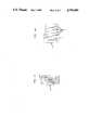
- FIG. 1is a transverse cross-sectional view of the buffer tube assembly of the invention
- FIG. 2is a longitudinal cross-section of the buffer tube assembly
- FIG. 3is a side elevational view of the apparatus of the invention.
- FIG. 4is a front view of the guidewheel of the apparatus of the invention.
- FIG. 4Ais an enlarged view of a portion of the guidewheel.
- FIG. 5is a view of the completed cable assembly.
- the buffer tube depicted in FIGS. 1 and 2is comprised of an outer covering 1 which is filled with soft filling material 2, such as thixotropic filling compound. Disposed within the tube are at least two coated single mode optical fibers which are loosely spaced with respect to each other. The loose spacing of the fibers assures that the fibers move freely and maintain their uniform length.
- the internal cross-sectional area of the buffer tube 1is larger than the cross-sectional area of the fibers; this allows the fibers room to move within the buffer tube 1.
- each fiberhas a length which is incrementally greater than the tube which encases it. This requires the fiber to follow a wavey path within the tube as long as the tubes are straight.
- the overlengthcauses the fibers to follow the general shape of the buffer tube 1.
- FIG. 3depicts the apparatus for manufacturing the buffer tube.
- the payoff stand 4hold a plurality of payoff reels 5 which provide equal and consistent tension to the optical fibers. Consistent tension is necessary to provide the fibers with equal elongation so that the uniform overall length may be maintained.
- the fibers 3pass between a capstan 6 and a mechanism for biasing the fibers against the capstan 6.
- the mechanismis a belt 7. This biasing mechanism causes friction between the fibers 3 and the capstan 6. This assures that all the fibers 3 and the capstan 6 are traveling at uniform speed.
- the guidewheel 8keeps the fibers sufficiently separated so that overlapping of the fibers 3 does not occur along their path length.
- the configuration of this wheelis best shown in FIGS. 4 and 4A.
- the guiding devicescomprises a series of grooves 9 which receive the fibers 3 and separate them in a horizontal plane. This separation prevents the fibers from bunching on the capstan 6 by putting them in a parallel but separated relationship.
- An extruder 10(FIG. 3), which has basic construction which is known to those skilled in the art, is used to process resin to form the buffer tube 1.
- a crosshead 11allows both injection of the filling material 2 and the disposition of the optical fibers 3 within the extruded buffer tube 1.
- the fibersare gathered into a random pattern by funnel-like means 11A and carried through the extruder During this operation, the fibers are carried by the viscous filling material.
- the speed of the capstan 6is dependent upon the speed of the buffer tube 1 issuing from the crosshead 11 and is controlled by control means 6A. This assures uniformity of overlength of each fiber along the length of the buffer tube assembly.
- the buffer tube 1may then be gathered onto a spool 16 or stranded into a cable 12 shown in FIG. 5.
- a strength member 13provides axial compression and axial tensile strength.
- the coating 14provides protection by buffering the contact between strength member 13 and the plurality of buffer tubes 1.
- the coating 14also provides sufficient circumferential space for the proper placement of the buffer tubes 1, depending on the number of buffer tubes 1 stranded about the strength member 13.
- the tubes 1 which contain the fibers 3are stranded with a finite pitch which results in additional elongation and contraction capability for the assembly. These additional capabilities are provided without inducing additional stress in the fibers 3.
- the strandingalso provides equal path lengths of the tubes regardless of their position within the assembled cable 12 which reduces fiber bending stress.
- the interstices between the tubes 1may or may not be filled with a material to prevent the ingress of moisture.
- a sheath 15is applied to the cable assembly 12 to provide extra protection.
Landscapes
- Physics & Mathematics (AREA)
- Engineering & Computer Science (AREA)
- General Physics & Mathematics (AREA)
- Optics & Photonics (AREA)
- Manufacturing & Machinery (AREA)
- Mechanical Engineering (AREA)
- Health & Medical Sciences (AREA)
- Ophthalmology & Optometry (AREA)
- Insulated Conductors (AREA)
Abstract
Description
Claims (3)
Priority Applications (1)
| Application Number | Priority Date | Filing Date | Title |
|---|---|---|---|
| US07/012,754US4741684A (en) | 1984-12-31 | 1987-02-09 | Optical cable with filling compound and parallel fibers |
Applications Claiming Priority (2)
| Application Number | Priority Date | Filing Date | Title |
|---|---|---|---|
| US06/687,601US4786137A (en) | 1984-12-31 | 1984-12-31 | Optical cable with filling compound and parallel fibers |
| US07/012,754US4741684A (en) | 1984-12-31 | 1987-02-09 | Optical cable with filling compound and parallel fibers |
Related Parent Applications (1)
| Application Number | Title | Priority Date | Filing Date |
|---|---|---|---|
| US06/687,601DivisionUS4786137A (en) | 1984-12-31 | 1984-12-31 | Optical cable with filling compound and parallel fibers |
Publications (1)
| Publication Number | Publication Date |
|---|---|
| US4741684Atrue US4741684A (en) | 1988-05-03 |
Family
ID=26683956
Family Applications (1)
| Application Number | Title | Priority Date | Filing Date |
|---|---|---|---|
| US07/012,754Expired - LifetimeUS4741684A (en) | 1984-12-31 | 1987-02-09 | Optical cable with filling compound and parallel fibers |
Country Status (1)
| Country | Link |
|---|---|
| US (1) | US4741684A (en) |
Cited By (10)
| Publication number | Priority date | Publication date | Assignee | Title |
|---|---|---|---|---|
| US5004574A (en)* | 1987-12-28 | 1991-04-02 | Hartley Sandt | Method of making a composite structural element |
| WO1992016347A1 (en)* | 1991-03-13 | 1992-10-01 | Hartley Sandt | Composite structural element and process for making same |
| US5348669A (en)* | 1990-06-22 | 1994-09-20 | Caschem, Inc. | Cable grease composition and articles incorporating same |
| US5433872A (en)* | 1990-06-22 | 1995-07-18 | Caschem, Inc. | Cable grease composition and articles incorporating same |
| US5576081A (en)* | 1987-12-28 | 1996-11-19 | Sandt; Hartley | Composite structural element and process for making same |
| US6421486B1 (en) | 1999-07-01 | 2002-07-16 | Fitel Usa Corp. | Extruded buffer tubes comprising polyolefin resin based color concentrates for use in fiber optic cables |
| EP1270177A3 (en)* | 2001-06-19 | 2003-09-24 | Hyung Ki Kim | Apparatus for manufacturing a resin tube with multiple inner conduits |
| US6711328B2 (en)* | 2001-07-12 | 2004-03-23 | Nkf Kabel B.V. | Installation bundle with spacer |
| US20100205581A1 (en)* | 2005-02-28 | 2010-08-12 | Skyler Technology, Inc. | Method and/or system for transforming between trees and strings |
| US10444435B2 (en)* | 2016-05-19 | 2019-10-15 | Ofs Fitel, Llc | Ribbon transition tool |
Citations (13)
| Publication number | Priority date | Publication date | Assignee | Title |
|---|---|---|---|---|
| US3516809A (en)* | 1964-03-23 | 1970-06-23 | Owens Corning Fiberglass Corp | Apparatus for forming fibers and control therefor |
| US4129468A (en)* | 1977-04-13 | 1978-12-12 | Bell Telephone Laboratories, Incorporated | Method and apparatus for manufacturing optical communication cables |
| US4153332A (en)* | 1974-07-30 | 1979-05-08 | Industrie Pirelli Societa Per Azioni | Sheathed optical fiber element and cable |
| US4154049A (en)* | 1978-06-08 | 1979-05-15 | Northern Telecom Limited | Method and apparatus for forming optical cables |
| GB2046471A (en)* | 1979-03-22 | 1980-11-12 | Telephone Cables Ltd | Tube containing optic fibre(s) and thixotropic fluid |
| US4289558A (en)* | 1978-06-30 | 1981-09-15 | Western Electric Company, Inc. | Methods of and apparatus for organizing fiber lightguides into a planar array |
| GB2085188A (en)* | 1980-09-26 | 1982-04-21 | Bicc Ltd | An improved optical cable |
| US4331379A (en)* | 1979-02-28 | 1982-05-25 | Siemens Aktiengesellschaft | Optical cable with thixotropic filling compound |
| US4372792A (en)* | 1981-10-15 | 1983-02-08 | Bicc Limited | Manufacture of a flexible stranded optical fiber body |
| US4373943A (en)* | 1979-03-23 | 1983-02-15 | Alain Gouronnec | Multiple fiber forming machine |
| US4397624A (en)* | 1980-10-30 | 1983-08-09 | U.S. Philips Corporation | Device for rendering a cable longitudinally watertight |
| US4629286A (en)* | 1982-07-05 | 1986-12-16 | Furukawa Electric Co., Ltd. | Coated optical fiber cable structure which prevents longitudinal cracks |
| US4640576A (en)* | 1984-06-26 | 1987-02-03 | Canada Wire And Cable Limited | Method and apparatus for tubing optical fibers |
- 1987
- 1987-02-09USUS07/012,754patent/US4741684A/ennot_activeExpired - Lifetime
Patent Citations (13)
| Publication number | Priority date | Publication date | Assignee | Title |
|---|---|---|---|---|
| US3516809A (en)* | 1964-03-23 | 1970-06-23 | Owens Corning Fiberglass Corp | Apparatus for forming fibers and control therefor |
| US4153332A (en)* | 1974-07-30 | 1979-05-08 | Industrie Pirelli Societa Per Azioni | Sheathed optical fiber element and cable |
| US4129468A (en)* | 1977-04-13 | 1978-12-12 | Bell Telephone Laboratories, Incorporated | Method and apparatus for manufacturing optical communication cables |
| US4154049A (en)* | 1978-06-08 | 1979-05-15 | Northern Telecom Limited | Method and apparatus for forming optical cables |
| US4289558A (en)* | 1978-06-30 | 1981-09-15 | Western Electric Company, Inc. | Methods of and apparatus for organizing fiber lightguides into a planar array |
| US4331379A (en)* | 1979-02-28 | 1982-05-25 | Siemens Aktiengesellschaft | Optical cable with thixotropic filling compound |
| GB2046471A (en)* | 1979-03-22 | 1980-11-12 | Telephone Cables Ltd | Tube containing optic fibre(s) and thixotropic fluid |
| US4373943A (en)* | 1979-03-23 | 1983-02-15 | Alain Gouronnec | Multiple fiber forming machine |
| GB2085188A (en)* | 1980-09-26 | 1982-04-21 | Bicc Ltd | An improved optical cable |
| US4397624A (en)* | 1980-10-30 | 1983-08-09 | U.S. Philips Corporation | Device for rendering a cable longitudinally watertight |
| US4372792A (en)* | 1981-10-15 | 1983-02-08 | Bicc Limited | Manufacture of a flexible stranded optical fiber body |
| US4629286A (en)* | 1982-07-05 | 1986-12-16 | Furukawa Electric Co., Ltd. | Coated optical fiber cable structure which prevents longitudinal cracks |
| US4640576A (en)* | 1984-06-26 | 1987-02-03 | Canada Wire And Cable Limited | Method and apparatus for tubing optical fibers |
Cited By (12)
| Publication number | Priority date | Publication date | Assignee | Title |
|---|---|---|---|---|
| US5004574A (en)* | 1987-12-28 | 1991-04-02 | Hartley Sandt | Method of making a composite structural element |
| US5576081A (en)* | 1987-12-28 | 1996-11-19 | Sandt; Hartley | Composite structural element and process for making same |
| US5348669A (en)* | 1990-06-22 | 1994-09-20 | Caschem, Inc. | Cable grease composition and articles incorporating same |
| US5433872A (en)* | 1990-06-22 | 1995-07-18 | Caschem, Inc. | Cable grease composition and articles incorporating same |
| WO1992016347A1 (en)* | 1991-03-13 | 1992-10-01 | Hartley Sandt | Composite structural element and process for making same |
| US6421486B1 (en) | 1999-07-01 | 2002-07-16 | Fitel Usa Corp. | Extruded buffer tubes comprising polyolefin resin based color concentrates for use in fiber optic cables |
| EP1270177A3 (en)* | 2001-06-19 | 2003-09-24 | Hyung Ki Kim | Apparatus for manufacturing a resin tube with multiple inner conduits |
| US6711328B2 (en)* | 2001-07-12 | 2004-03-23 | Nkf Kabel B.V. | Installation bundle with spacer |
| US20040071429A1 (en)* | 2001-07-12 | 2004-04-15 | Nkf Kabel B.V. | Installation bundle with spacer |
| US6879760B2 (en)* | 2001-07-12 | 2005-04-12 | Nkf Kabel B.V. | Installation bundle with spacer |
| US20100205581A1 (en)* | 2005-02-28 | 2010-08-12 | Skyler Technology, Inc. | Method and/or system for transforming between trees and strings |
| US10444435B2 (en)* | 2016-05-19 | 2019-10-15 | Ofs Fitel, Llc | Ribbon transition tool |
Similar Documents
| Publication | Publication Date | Title |
|---|---|---|
| US4786137A (en) | Optical cable with filling compound and parallel fibers | |
| US6785450B2 (en) | Self-supporting fiber optic cable | |
| US10107980B1 (en) | Optical fiber cable with rollable ribbons contained in a central tube without intended stranding | |
| EP1567901B1 (en) | High count telecommunication optical cable with controlled fiber length | |
| US4199224A (en) | Communication cable utilizing optical transmission elements | |
| CA2015306C (en) | Optical fiber cable | |
| US6775444B1 (en) | Fiber optic assemblies and methods of making the same | |
| US6584251B1 (en) | Solid stranding flextube unit | |
| JPH05142454A (en) | Composite buffer cable | |
| NZ234274A (en) | Optical fibre cable; slack in internal fibre | |
| US4741684A (en) | Optical cable with filling compound and parallel fibers | |
| US4435238A (en) | Manufacturing process for a low loss optical fiber cable | |
| US4759602A (en) | Method of manufacturing an optical transmission element | |
| US4792422A (en) | Method of making an optical fiber cable | |
| GB2215081A (en) | Optical fibre cable | |
| WO2005043208A1 (en) | Fiber optic assemblies, cables, and manufacturing methods therefor | |
| KR100342519B1 (en) | Loose tube plenum cable | |
| JP7732801B2 (en) | Intermittently adhesive optical fiber ribbon, optical fiber cable | |
| KR100395447B1 (en) | Composite optical fiber processing ground wire and its manufacturing method | |
| JP3346254B2 (en) | Optical fiber | |
| GB2138965A (en) | Optical fibre cable and method of manufacture | |
| JP7704606B2 (en) | Intermittently adhesive optical fiber ribbon, optical fiber cable, and method for manufacturing intermittently adhesive optical fiber ribbon | |
| US20240231025A1 (en) | Optical cable | |
| EP3314322B1 (en) | Method of manufacturing an aerial micromodule optical cable | |
| GB1584457A (en) | Optical cables |
Legal Events
| Date | Code | Title | Description |
|---|---|---|---|
| FEPP | Fee payment procedure | Free format text:PAYOR NUMBER ASSIGNED (ORIGINAL EVENT CODE: ASPN); ENTITY STATUS OF PATENT OWNER: LARGE ENTITY | |
| STCF | Information on status: patent grant | Free format text:PATENTED CASE | |
| AS | Assignment | Owner name:ALCATEL NA, INC., 100 PENNY ROAD, CLAREMONT, NC., Free format text:ASSIGNMENT OF ASSIGNORS INTEREST.;ASSIGNOR:ERICSSON, INC.;REEL/FRAME:004923/0892 Effective date:19880412 Owner name:ALCATEL NA, INC., A CORP OF DE., NORTH CAROLINA Free format text:ASSIGNMENT OF ASSIGNORS INTEREST;ASSIGNOR:ERICSSON, INC.;REEL/FRAME:004923/0892 Effective date:19880412 | |
| FEPP | Fee payment procedure | Free format text:PAYER NUMBER DE-ASSIGNED (ORIGINAL EVENT CODE: RMPN); ENTITY STATUS OF PATENT OWNER: LARGE ENTITY Free format text:PAYOR NUMBER ASSIGNED (ORIGINAL EVENT CODE: ASPN); ENTITY STATUS OF PATENT OWNER: LARGE ENTITY | |
| AS | Assignment | Owner name:ALCATEL NA CABLE SYSTEMS, INC., A CORP. OF DELAWA Free format text:ASSIGNMENT OF ASSIGNORS INTEREST.;ASSIGNOR:ALCATEL NA, INC., 39 SECOND STREET NW, HICKORY, NORTH CAROLINA 28603 ACORP. OF DELAWARE;REEL/FRAME:005518/0106 Effective date:19900924 | |
| FPAY | Fee payment | Year of fee payment:4 | |
| FPAY | Fee payment | Year of fee payment:8 | |
| FEPP | Fee payment procedure | Free format text:PAYER NUMBER DE-ASSIGNED (ORIGINAL EVENT CODE: RMPN); ENTITY STATUS OF PATENT OWNER: LARGE ENTITY Free format text:PAYOR NUMBER ASSIGNED (ORIGINAL EVENT CODE: ASPN); ENTITY STATUS OF PATENT OWNER: LARGE ENTITY | |
| FPAY | Fee payment | Year of fee payment:12 | |
| AS | Assignment | Owner name:NEXANS, FRANCE Free format text:ASSIGNMENT OF ASSIGNORS INTEREST;ASSIGNOR:ALCATEL, NA CABLE SYSTEMS, INC.;REEL/FRAME:012302/0736 Effective date:20011019 |