US4740963A - Voice and data communication system - Google Patents
Voice and data communication systemDownload PDFInfo
- Publication number
- US4740963A US4740963AUS06/824,067US82406786AUS4740963AUS 4740963 AUS4740963 AUS 4740963AUS 82406786 AUS82406786 AUS 82406786AUS 4740963 AUS4740963 AUS 4740963A
- Authority
- US
- United States
- Prior art keywords
- signal
- voice
- digital
- data
- voice signal
- Prior art date
- Legal status (The legal status is an assumption and is not a legal conclusion. Google has not performed a legal analysis and makes no representation as to the accuracy of the status listed.)
- Expired - Fee Related
Links
- 238000004891communicationMethods0.000titleclaimsabstractdescription38
- 239000002131composite materialSubstances0.000claimsabstractdescription70
- 230000005540biological transmissionEffects0.000claimsdescription21
- 238000000034methodMethods0.000claimsdescription20
- 238000013144data compressionMethods0.000claimsdescription17
- 230000003750conditioning effectEffects0.000claims2
- 239000000872bufferSubstances0.000description19
- 238000012360testing methodMethods0.000description11
- 238000009432framingMethods0.000description10
- 230000011664signalingEffects0.000description6
- 238000001514detection methodMethods0.000description5
- 238000010586diagramMethods0.000description5
- 230000006870functionEffects0.000description5
- 230000002441reversible effectEffects0.000description4
- 230000003044adaptive effectEffects0.000description2
- 238000006243chemical reactionMethods0.000description2
- 239000000470constituentSubstances0.000description2
- 230000000737periodic effectEffects0.000description2
- 238000012545processingMethods0.000description2
- 238000004092self-diagnosisMethods0.000description2
- 230000004075alterationEffects0.000description1
- 230000000295complement effectEffects0.000description1
- 230000008878couplingEffects0.000description1
- 238000010168coupling processMethods0.000description1
- 238000005859coupling reactionMethods0.000description1
- 238000006880cross-coupling reactionMethods0.000description1
- 238000013461designMethods0.000description1
- 238000002592echocardiographyMethods0.000description1
- 238000010348incorporationMethods0.000description1
- 238000012986modificationMethods0.000description1
- 230000004048modificationEffects0.000description1
- 230000008569processEffects0.000description1
- 230000009467reductionEffects0.000description1
- 230000000717retained effectEffects0.000description1
- 230000009131signaling functionEffects0.000description1
- 230000005236sound signalEffects0.000description1
- XLYOFNOQVPJJNP-UHFFFAOYSA-NwaterSubstancesOXLYOFNOQVPJJNP-UHFFFAOYSA-N0.000description1
Images


Classifications
- H—ELECTRICITY
- H04—ELECTRIC COMMUNICATION TECHNIQUE
- H04M—TELEPHONIC COMMUNICATION
- H04M11/00—Telephonic communication systems specially adapted for combination with other electrical systems
- H04M11/06—Simultaneous speech and data transmission, e.g. telegraphic transmission over the same conductors
- H04M11/068—Simultaneous speech and data transmission, e.g. telegraphic transmission over the same conductors using time division multiplex techniques
- H—ELECTRICITY
- H04—ELECTRIC COMMUNICATION TECHNIQUE
- H04J—MULTIPLEX COMMUNICATION
- H04J3/00—Time-division multiplex systems
- H04J3/16—Time-division multiplex systems in which the time allocation to individual channels within a transmission cycle is variable, e.g. to accommodate varying complexity of signals, to vary number of channels transmitted
- H04J3/1682—Allocation of channels according to the instantaneous demands of the users, e.g. concentrated multiplexers, statistical multiplexers
- H04J3/1688—Allocation of channels according to the instantaneous demands of the users, e.g. concentrated multiplexers, statistical multiplexers the demands of the users being taken into account after redundancy removal, e.g. by predictive coding, by variable sampling
Definitions
- This inventionrelates generally to telephone voice communication systems, and, more particularly, to systems that multiplex together both voice and digital data signals.
- Typical telephone voice communication systemsinclude a great number of remote users, each with its own remote telephone unit interfacing with a dedicated two-wire, full-duplex line.
- a central office apparatusreceives the analog voice signal transmitted from each user and transmits back a corresponding analog voice signal over the same full-duplex line.
- the central office apparatusincludes an analog switch array for routing the individual voice signals to their desired destinations.
- DLCdigital loop carrier
- the voice and data signalsare separated there and routed to separate destinations.
- One such digital data signalwould have a relatively low data rate suitable, for example, for carrying signaling information for water meters, burglar and fire alarms and the like.
- the other data signalwould have a higher data rate suitable, for example, for transmitting data to and from a personal computer or the like.
- the usual technique for simultaneously transmitting both voice and digital datais to transmit the signals on different lines or to frequency-division multiplex them together on a single line.
- the voice signalis ordinarily retained in its analog format, with a limited bandwidth, and the two digital data signals are modulated onto different subcarriers at frequencies spaced above the voice signal.
- Such a systemis generally effective at simultaneously transmitting and receiving both voice and digital data signals, it has not been proven to be entirely satisfactory.
- the quality of the voice signalis unduly distorted by the band limiting, and the upper limits on the data rates of the two digital data signals is considered to be unduly low.
- the present inventionis embodied in a voice communication system, and a related method, for transmitting simultaneously both a voice signal and a digital data signal, with reduced distortion to the voice signal and with a higher digital data rate than was previously achieved for a given combined bandwidth.
- the systemincludes a remote user unit having analog-to-digital (A/D) converter means for digitizing an analog voice signal received, for example, from an external telephone unit, and data compression means for reducing the data rate of the digitized signal.
- Multiplexermeans time-division multiplexes the compressed voice signal with a first digital data signal to produce a composite digital signal having a data rate substantially the same as the original digitized voice signal.
- Selector meansselectively connects either the analog voice signal or the composite digital signal to an output terminal, for transmission to a central office.
- the voice communication system of the inventionis preferably adapted for use in a telephone system that simultaneously transmits and receives signals over a common full-duplex line.
- the transmit composite signalis transmitted from the remote user unit to a central office terminal for decoding and routing to the appropriate destinations, and a corresponding receive composite signal is received simultaneously in return.
- the remote user unitfurther includes demultiplexer means for time-division demultiplexing the signal to produce a receive compressed voice signal and a receive digital data signal.
- Data expansion meansdecompresses the receive compressed voice signal
- D/A converter meansconverts the decompressed voice signal to a corresponding receive analog voice signal. This latter signal can be transmitted to the external telephone unit.
- the selector meansselectively directs the receive signal directly to the telephone unit, bypassing the demultiplexer, data expansion, and D/A converter means.
- the central office terminalreceives composite digital signals transmitted from a number of remote users and initially separates the compressed voice signal from the digital data signal in each composite signal it receives.
- the separated digital data signalsare directed to appropriate output terminals for further transmission, and the separated compressed voice signals are converted back into their original analog voice formats.
- These re-created analog voice signalsare transmitted to a suitable switch array for routing to their appropriate destinations.
- a digital loop carrier (DLC) unit having multiplexer meansis included to time-division multiplex together the various composite signals.
- a corresponding DLC unit having corresponding demultiplexer meansis located at the central office, for again separating the composite signals from each other. Signaling bits can be removed from the interleaved composite signals transmitted over the link between the two DLC units.
- the multiplexer and demultiplexer means of these two DLC unitscan similarly transmit a corresponding plurality of interleaved composite signals in the opposite direction, toward the remote users.
- the selector means located at each remote user unitincludes means for sensing a failure in predetermined ones of its constituent elements and for selectively connecting the analog voice signal to the unit's output terminal when that occurs.
- the received signalis likewise connected directly to the external telephone unit or other voice input when that occurs, thus bypassing the means where a failure has been detected.
- the composite digital signal transmitted to each remote user unitincludes a code signal indicating the desired operating conditions of both the selector means and the data compression, multiplexer, data expansion and demultiplexer means.
- Each remote user unitincludes means for detecting these code signals and for configuring the unit's respective means, accordingly.
- loopback meansare interposed between various elements of the remote user unit, the DLC units, and the central office terminal, for use in selectively testing the various elements of the units.
- each loopback meansconnects a signal being output by a particular element back into the element's receive terminal normally used for the signal being transmitted in the opposite direction. Selective operation of these loopback elements can be controlled, for example, by the code signals selectively transmitted from the central office to each remote user unit.
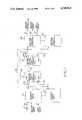
- FIG. 1is a simplified block diagram of a voice and data communication system for transmitting and receiving both voice and data signals to and from a number of remote users;
- FIG. 2is a simplified block diagram of one remote user unit from the voice and data communication system of FIG. 1;
- FIG. 3is a simplified block diagram of the remote digital loop carrier, unit of FIG. 1;
- FIG. 4is a simplified block diagram of the central office digital loop carrier unit of FIG. 1;
- FIG. 5is a simplified block diagram of the central office terminal of FIG. 1.
- FIG. 1there is shown a communication system for transmitting and receiving both voice and digital data signals to and from a large number of remote users.
- Each remote useris provided with a separate remote user unit 11 for combining together voice and digital data signals and for transmitting and receiving such combined signals to and from a common central office.
- the remote user unitinterfaces with an analog voice signal source such as a conventional full-duplex telephone unit 13, as well as lines 15 and 17 that carry medium and low speed digital data signals.
- a remote digital loop carrier (DLC) unit 19multiplexes together the combined voice and digital data signals supplied to it on lines 21a-21n from the various remote user units 11a-11n and transmits these multiplexed signals over a common DS1 line 23 to the central office.
- a corresponding central office DLC unit 25demultiplexes the signals that originated at the various remote user units and supplies these demultiplexed signals on lines 27a-27n to separate central office terminals 29a-29n. These terminals, in turn, separate the voice and digital data signals and direct them to predetermined destinations via lines 31, 33 and 35. Simultaneously, voice and data signals are transmitted back from the central office terminals to the various remote user units in a similar fashion. This provides full-duplex communication. In some instances, the voice and digital data signals can bypass the remote and central office DLC units 19 and 25, as indicated by the lines 37a-37n.
- FIG. 2depicts one remote user unit 11, which combines voice and digital data signals for a particular remote user and transmits these signals over either a common line 21 to the remote DLC unit 19 or a common line 37 directly to the corresponding central office terminal 29.
- the remote user unitalso receives back on line 21 (or 37) a similar grouping of voice and digital data signals and directs these signals to the appropriate input/output terminals 13, 15 and 17.
- the remote user unit 11receives a standard analog voice signal on line 39 from the telephone unit 13 and medium and low speed digital data signals on lines 15 and 17, respectively.
- the medium data signalwhich can have a bit rate of up to 19.2-kilobits per second, is received through a standard RS-232 connector 41
- the low speed data signalwhich can have a bit rate of up to 1.2-kilobits per second, is received through a second RS-232 connector 43.
- Return voice and data signalsare also transmitted out through these respective terminals.
- the remote user unit 11includes a transformer, CODEC and echo-canceling hybrid circuit 45 for digitizing the analog voice signal supplied on lines 39, a data compressor 47 for reducing the data rate of the digitized voice signal, and a multiplexer/demultiplexer 49 for time-division multiplexing together the compressed voice signal and the medium and low speed digital data signals supplied to the unit via the respective connectors 41 and 43.
- a modulator 50subsequently modulates the multiplexed signal onto a carrier for ultimate output on line 21.
- the voice component of the output signalcan be re-created subsequently, with substantially less distortion than occurs in prior voice and data communication systems of this kind.
- the reduction in the data rate of the digitized voice signal provided by the data compressor 47makes sufficient bandwidth available for the digital data signals to permit higher data rates than were previously available in prior systems.
- the remote user unit 11includes two double-pole, double-throw switches 51 and 53 that are used to configure the unit in either of two operating modes, i.e., a SYSTEM mode or a POTS (Plain Old Telephone System) mode.
- a SYSTEM modethe unit operates as described briefly above, to digitize the analog voice signal received from the telephone unit 13 and to combine the digitized voice signal with two digital data signals.
- POTS modethe unit simply transmits the analog voice signal without alteration.
- the analog voice signalis coupled on lines 55 from the first switch 51 to the transformer, CODEC and echo-canceling hybrid circuit 45.
- This circuitperforms the standard signaling functions commonly associated with telephone systems, including ring trip and off-hook signaling, as well as ring generation.
- the circuitincludes a conventional DNIC (Data Network Interface Controller) device for digitizing the analog voice signal and an additional device for reducing the cross-coupling of the transmitted and received signals, which otherwise can create undesired echos.
- DNICData Network Interface Controller
- the transformer, CODEC and echo-canceling hybrid circuit 45outputs the digitized voice signal on eight parallel lines 56 to a loopback device 57 and, in turn, on lines 58 to the data compressor 47.
- the CODEC's sample rateis 8 kilohertz, which is adequate for the 3.2 kilohertz analog voice bandwidth.
- the data compressorcompresses these successive 8-bit bytes into corresponding 4-bit bytes at the same baud rate, using an adaptive, differential encoding algorithm. Such algorithms are well-known and need not be described in detail here.
- the compressed 4-bit bytesare transmitted on lines 59 to the multiplexer/demultiplexer 49.
- the medium speed data signal supplied to the unit 11 via the RS-232 connector 41is transmitted on line 61 to a loopback device 63 and, in turn, on line 65 to the multiplexer/demultiplexer.
- the low speed data signal supplied to the unit via the RS-232 connector 43is transmitted on line 67 to a loopback device 69 and, in turn, on line 71 to the multiplexer/demultiplexer.
- the multiplexer/demultiplexer 49interleaves the successive 4-bit compressed voice samples with the medium and low speed digital data signals to form a 64-kilobit per second, 8-bit parallel signal for output on lines 73. Half of this data represents the original analog voice signal, while the remaining half represents the two digital data signals as well as certain control bits.
- control bitsare useful, for example, in signaling the central office and in providing headers and parity check.
- these control bitscan include redundant encoding in the least significant bit position of each 8-bit byte, which is periodically eliminated in many conventional telephone links.
- a buffer 75which includes a universal-asynchronous receiver/transmitter (UART), receives the successive 8-bit parallel bytes on lines 73 from the multiplexer/demultiplexer 49.
- This bufferadds two framing bits to each 8-bit byte, and serializes the data to produce an 80-kilobit per second serial data signal, which is output on line 77.
- the two added framing bits for each 8-bit byteare, for example, grafted at the beginning and ending of each byte, to assist in subsequent de-encription.
- the 80-kilobit per second digital signalis transmitted on line 77 from the buffer to a loopback device 79 and, in turn, on line 81 to the modulator 50, for modulation on an 80 kilohertz carrier.
- This modulated signalis then transmitted on line 83 to a transformer 85 and, in turn, on lines 87 to the switch 53, for output by the unit on line 21.
- the transformeris a conventional device that is impedance matched with a standard "U" interface or "DS0" line such as line 21.
- the remote user unit 11not only formats and transmits a combined voice and digital data signal, but also simultaneously receives back a similar combined voice and digital data signal.
- This latter receive signalis received on the same DS0 line 21 and connected through the switch 53 and lines 87 to the transformer 85.
- the receive signalis then coupled on line 89 to a demodulator 91, which demodulates it from its 80 kilohertz carrier to produce an 80-kilobit per second serial data signal.
- the serial data signalis transmitted on line 93 to the loopback device 79 and, in turn, on line 95 to the buffer 75.
- the bufferremoves the framing bits immediately preceding and following each 8-bit byte and reformats the signal into a 64-kilobit per second, 8-bit parallel signal.
- the successive 8-bit parallel bytesare transmitted on lines 97 to the multiplexer/demultiplexer 49, which separates out the particular bits in each byte that represent the respective voice signal, medium speed digital data signal, and low speed digital data signal.
- the latter two signalsare transmitted on lines 65 and 71, respectively, to the respective loopback devices 63 and 69 and RS-232 terminals 41 and 43.
- the 4-bit bytes corresponding to the received voice signalare transmitted on lines 99 from the multiplexer/demultiplexer 49 to a data expander 101, which performs the inverse function of the data compressor 47. In particular, it expands each 4-bit byte into a corresponding 8-bit byte in accordance with the same adaptive, differential encoding algorithm.
- the expanded 8-bit bytesare then transmitted on lines 103 to the loopback device 57, and, in turn, on lines 104 to the transformer, CODEC and echo-canceling hybrid circuit 45, which converts the data back into its original analog format and properly buffers the signal for coupling through the switch 51 to the telephone unit 13.
- the normal operating mode of the user unit 11is the POTS mode, in which the analog voice signals bypass the unit's various digitizing and multiplexing functions via a full-duplex line 105.
- the unitautomatically switches over to the SYSTEM mode upon receipt of a particular dual-tone, multifrequency (DTMF) signal on line 21 from the remote DLC unit 19 (or on line 37 of the central office terminal 29).
- DTMFdual-tone, multifrequency
- a SYSTEM mode tone detector 107monitors the bypass line 105 and generates an appropriate control signal when it detects the specified DTMF signal. This control signal is transmitted on line 109 to the multiplexer/demultiplexer 49, which, in turn, switches the two switches 51 and 53 to their SYSTEM positions via control line 111.
- the remote user unit 11returns to the POTS mode in either of two ways. First, if a significant failure (such as a power outage) is ever detected in any of the remote user unit's functional elements, the two switches 51 and 53 are automatically switched to their POTS positions. A self-diagnosis circuit 113 periodically scans certain test points in the remote user unit to ensure that the unit is operating properly. If this circuit ever detects that a failure has occurred, it terminates its periodic resetting via line 115 of a watchdog timer circuit 117, such that the timer circuit eventually reaches a prescribed number.
- a significant failuresuch as a power outage
- the timer circuitWhen it does, the timer circuit outputs an appropriate control signal on line 119 to signal an alarm logic circuit 121 to instruct the multiplexer/demultiplexer 49 via line 123 that a return should be made to the POTS mode.
- the multiplexer/demultiplexerresponds by inserting appropriate bits into its digital data output signal to indicate that a failure has occurred and that the unit will be switching to its POTS mode. Immediately thereafter, the multiplexer/demultiplexer switches the two switches 51 and 5 to their respective POTS positions via line 111.
- a second way for the remote user unit 11 to switch back to the POTS mode from the SYSTEM modeis by the detection of a particular code in the signal the unit receives from the central office terminal 29 (FIG. 1) via the DS0 line 21.
- the multiplexer/demultiplexer 49includes a special code detect circuit that monitors the incoming 8-bit bytes of the receive signal to detect when this particular code is received. When such a code is detected, the multiplexer/demultiplexer inserts an appropriate code of its own into the 8-bit transmit bytes, to indicate that the POTS mode code has been detected and it immediately thereafter switches the switches 51 and 53 via the control line 111.
- Special code signalsare also transmitted periodically to the remote user unit 11 from the central office terminal 29 to establish various operating parameters for the unit.
- These code signalscan indicate, for example, the desired bit rates of the medium and low speed digital data signals, as well as certain conditions for the data compression algorithm implemented by the data compressor 47 and data expander 101.
- the multiplexer/demultiplexeroutputs an appropriate reply code for transmission out on the DS0 line 21, to indicate that it has properly received the format code signal.
- the remote user unit 11includes loopback devices 57, 63, 65 and 79 for use in selectively looping back the signals the unit is transmitting or receiving. This is useful in permitting an effective testing of limited portions of the unit, to isolate possible failures.
- the loopback device 79if the loopback device 79 is operating, the receive signal output by the demodulator 91 on line 93 is coupled back via line 81 to the input terminal of the modulator 50. This permits testing from the central office of just the modulator and demodulator, transformer 85 and switch 53 of the remote user unit.
- operation of either of the loopback devices 63 and 69permits selective testing of the entire digital data portion of the unit except for the two RS-232 connectors 41 and 43. Additional loopback devices can also be utilized to test other portions of the system, such as the RS-232 connectors themselves.
- the composite digital signals output by the various remote user units 11are transmitted on the DS0 lines 21a-21n to the remote DLC unit 19.
- This latter unittime-division multiplexes the various composite signals together, for transmission over a single "DS1" line 23 a considerable distance to the central office DLC unit 25.
- the remote DLC unitdelivers to the various remote user units over the same DS0 lines a similar set of composite digital signals, each including a compressed, digitized voice signal and medium and low speed digital data signals.
- the remote DLC unit 19includes separate interface cards 125a-125n (FIG. 1) for the respective remote user units 11a-11n, as well as common equipment to which all of the interface cards are connected.
- Each interface carddemodulates the composite digital signal received from a particular remote user unit 11.
- Each such cardalso strips off the two signaling bits at the beginning and end of each 8-bit byte in the 80-kilobit per second data signal, to provide a 64-kilobit per second, 8-bit parallel data sequence.
- the 64-kilobit per second data sequences from all of the interface cardsare supplied to the common equipment, which time-division multiplexes them together for transmission to the central office.
- FIG. 3depicts the common equipment 126 and one interface card 125 from the remote DLC unit 19.
- the interface card portion of the unitis divided into two sections. The upper section is utilized when the unit operates in the POTS mode, and the lower section is utilized when the unit operates in the system mode.
- a double-pole, double-throw switch 127directs the signal supplied to the unit on the DS0 line 21 to either the upper, POTS mode section, or the lower, SYSTEM mode section.
- the switch 127When the signal supplied to the remote DLC unit 19 includes the digitized voice plus data signal, the switch 127 is in the SYSTEM position and the received signal is initially processed in a conventional transformer 129 that is properly matched to the DS0 line 21. From there, the received signal is carried on line 131 to a demodulator 133, which demodulates the signal to an 80-kilobit per second baseband digital data signal. This baseband signal is carried on line 135 to a loopback device 137 and, in turn, on line 139 to a buffer 141, which separates the signal into successive 10-bit bytes and then eliminates the two framing bits that were added to each 8-bit byte in the remote user unit 11.
- the bufferwhich can include a conventional universal-asynchronous receiver/transmitter (UART) then outputs the successive 8-bit bytes in parallel on lines 143.
- An interface circuit 145receives the successive 8-bit parallel bytes and, under the control of appropriate timing signals received on line 147 from the common equipment 126, outputs the data on line 149 to the common equipment for interleaving with the corresponding data similarly provided by other interface cards 125.
- the remote DLC unit 19further functions to transmit composite digital signals to each of its associated remote user units 11.
- the common equipment 126supplies on line 151 to the interface circuit 145 of each interface card 125 a sequence of 8-bit bytes extracted from the time-division multiplexed signal it receives on the DS1 line 23.
- the interface circuitrelays these 8-bit parallel bytes on lines 153 to the buffer 141, which grafts two framing bits onto the beginning and end of each byte and converts the parallel data into an 80-kilobit per second serial data signal.
- This signalis carried on line 155 to the loopback device 141 and, in turn, on line 157 to a modulator 159 for modulation on an 80-kilohertz carrier.
- the modulated carrieris then transmitted on line 161 to the transformer 129, which transmits it through the switch 127 to the DS0 line 21.
- the switch 127When merely analog voice signals are being transmitted over the DS0 line 21, the switch 127 is in the POTS position and only the upper, POTS mode section of the remote DLC unit 19 is operational. In this operating mode, the analog voice signal supplied to the unit is carried on lines 163 from the switch to a transformer and filter 165, which is properly matched to the DS0 line. This is a conventional circuit that further detects the standard ring trip and off-hook signals, for processing in a conventional fashion.
- the suitably terminated analog voice signalis transmitted on line 167 to a sample and hold interface circuit 169, which, under the control of a timing signal supplied to it on line 171 from the common equipment 126, transmits digitized samples of the voice signal on line 173 to the common equipment, for interleaving with the signals provided by other interface cards 125.
- the transformer and filter, sample and hold interface circuit, and common equipmentare all conventional circuits normally present in the prior DLC units of this general kind.
- the analog voice signal for transmission out to the remote user unit 11is supplied in digital form by the common equipment 126 on line 175.
- the sample and hold interface circuit 169converts this digitized signal back to its original analog format, for transmission on line 177 to the transformer and filter 165 and, in turn, on lines 163 to the switch 127 and the DS0 line 21.
- the interface card 125 of the remote DLC unit 19includes a POTS-to-SYSTEM tone detector 178 that monitors via line 179 the analog voice signal being transmitted to the corresponding remote user unit 11. When it detects a prescribed DTMF signal, this detector outputs an appropriate control signal on line 180 to the interface circuit 145.
- the interface circuitresponds by sending an appropriate code signal back to the central office terminal 29 indicating that the DTMF signal has been received.
- the interface circuitalso outputs an appropriate control signal on line 181 to a POTS logic circuit 182 that switches the mode switch 127 to the POTS position via control line 183.
- the POTS logic circuit 182monitors via line 181 the successive 8-bit bytes received by the interface circuit 145 on line 151 from the common equipment 126.
- the logic circuitdetects a particular code instructing the card to switch back to the POTS mode, the circuit switches the POTS/SYSTEM switch 127 via line control line 183.
- the loopback device 137is utilized in the same fashion as the loopback devices of the remote user unit 11.
- the interface circuit 145detects a particular code in the successive 8-bit bytes it receives from the central office via the common equipment 126, it conditions the loopback device to connect the 80-kilobit per second serial data signal output by the buffer 141 on line 155 back on line 139 to an input terminal of the same buffer. This permits selective testing of the unit's common equipment, interface circuit and buffer.
- the remote DLC unit 19is typically located at least several miles from the central office, this distance underscoring the very need for the unit.
- the systemcan eliminate the need for connecting a separate cable between the central office and each remote user.
- the signal transmitted on the DS1 linehas a bit rate of about 1.5 megabits per second.
- the central office DLC unit 2receives the multiplexed signal carried on the DS1 line 23 from the remote DLC unit 19 and it demultiplexes this signal to re-create the modulated composite digital signals originally generated by the various remote user units 11a-11n.
- the central office DLC unitincludes a significant amount of common equipment of the kind typically included in conventional DLC units and further includes separate interface cards 185a-185n for processing the signals associated with the various remote user units 11a-11n.
- the common equipment 187 and one interface card 185 of the central office DLC unit 25are depicted in FIG. 4. It will be observed that the depicted equipment is substantially identical to the remote DLC unit 19; the only significant difference is that the two units are depicted in reverse orientations.
- the signal received on the DS1 line 23is initially processed by the common equipment 187, which demultiplexes the signal to produce a sequence of 8-bit bytes for each remote user.
- the common equipment 187demultiplexes the signal to produce a sequence of 8-bit bytes for each remote user.
- the corresponding interface card 185 of the central office DLC unit 25When a particular remote user is operating in the SYSTEM mode, so too is the corresponding interface card 185 of the central office DLC unit 25.
- a double-pole, double-throw mode switch 189is configured in the SYSTEM position, and the lower, SYSTEM mode section of the card is operational.
- the successive 8-bit bytes for this particular interface card 185are supplied in serial form on line 191 from the common equipment to an interface circuit 193.
- the interface circuitconverts the serial data into corresponding parallel data for transmission on lines 195 to a buffer 197, which grafts prescribed framing bits onto each byte and converts it into a corresponding serial data signal. These framing bits aid in subsequent detection of the data.
- This buffercan include a conventional universal-asynchronous receiver/transmitter (UART).
- UARTuniversal-asynchronous receiver/transmitter
- the resulting 80-kilobit per second serial data signalis transmitted on line 199 to a loopback device 201 and, in turn, on line 203 to a modulator 205, for modulation on an 80-kilohertz carrier.
- the modulated signalis then supplied on line 207 to a transformer 209, of conventional design, for output on lines 211 to the mode switch 189 and the DS0 output line 27.
- the modulated carrier signal received on the full-duplex DS0 line 27is transmitted through the mode switch 189 and along lines 211 to the transformer 209, which is impedance matched to the DS0 line.
- the transformersupplies this signal on line 213 to a demodulator 215, for demodulation to an 80l -kilobit per second serial data signal.
- This data signalis transmitted on line 217 to the loopback device 201 and, in turn, on line 219 to the buffer 197, for detection and removal of the framing bits associated with each 8-bit byte and for conversion into a corresponding 64-kilobit per second, 8-bit parallel data signal.
- This data signalis transmitted over lines 221 to the interface circuit 193, which, under the control of timing signals supplied to it on line 223 from the common equipment 187, serializes the signal and supplies it at the appropriate time intervals on line 225 to the common equipment.
- the mode switch 189When a given interface card 185 of the central office DLC unit 25 is intended to carry merely full-duplex analog voice signals, the mode switch 189 is switched to the POTS position and the upper, POTS mode section of the card is operational.
- the voice signal originally generated by the corresponding remote useris supplied to the upper section of the card in digital form on a transmit line 227.
- a sample and hold interface circuit 229returns this digital signal to its original analog format and transmits the analog signal on line 231 to a filter and transformer 233 for output on lines 235 to the mode switch and, in turn the DS0 line 27.
- the analog voice signal intended to be transmitted back to the same remote useris received by the filter and transformer 233 on the same full-duplex lines 235 and relayed, in turn, on line 236 to the sample and hold interface circuit 229.
- This circuitdigitizes the analog voice signal and, under the control of appropriate timing signals received on line 237 from the common equipment 187, supplies a succession of 8-bit bytes to the common equipment on line 239.
- the filter and transformer, sample and hold interface circuit, and common equipmentare all conventional circuits normally present in prior DLC units of this general kind.
- the interface cards 185 of the central office DLC unit 25each include a POTS-to-SYSTEM DTMF signal detector 241 that monitors via line 243 the analog voice signal being transmitted to the corresponding remote user unit 11. When it detects a prescribed DTMF signal, this detector outputs an appropriate control signal on line 245 to the interface circuit 193.
- the interface circuitresponds by sending an appropriate code signal back to the central office terminal 29 indicating that the DTMF signal has been received.
- the interface circuitalso outputs an appropriate control signal on line 247 to a POTS logic circuit 249 that switches the mode switch 189 to the POTS position via control line 251.
- the interface circuit 193detects an appropriate code signal received in the digital data signal supplied from the central office terminal 29.
- the interface circuitresponds by sending back to the central office terminal an appropriate code signal indicating that the POTS mode signal has been received and immediately thereafter outputs a control signal on line 247 to the POTS logic circuit 249, causing it to switch the mode switch 189 back to the POTS position via control line 251.
- the loopback device 201is utilized whenever the interface circuit 193 detects an appropriate code signal in the successive 8-bit bytes it receives from the central office terminal 29.
- the loopback deviceconnects the demodulated 80-kilobit per second data signal output by the demodulator 215 back to the input terminal of the modulator 205, which then modulates the signal and returns it to the central office terminal. This permits the selective testing of the modulator, demodulator, transformer 209 and mode switch 189 of the interface card 185.
- Each interface card 185 of the central office DLC unit 25transmits the modulated data signal (or analog voice signal, in the POTS mode) on the DS0 line 27 to a separate central office terminal 29.
- the central office terminalreturns the modulated signal to its baseband format, separates the voice data from the medium and low speed digital data signals, and re-creates the original analog voice signal.
- the analog voice signal, medium speed digital data signal, and low speed digital data signalare output by the central office terminal on lines 31, 33 and 35, respectively.
- One central office terminal 25is depicted in FIG. 5. It will be observed that the unit is substantially identical to the remote user unit 11. One difference is that the central office terminal unit is arranged on the sheet with the DS0 line 27 located on its left side, rather than its right side. Another difference is that the central office terminal further includes a manually-operable mode switch 253 for use in selecting the POTS or SYSTEM operating mode and a control data terminal 255 for use in the selective testing and control of the system's various units, for example, using the various loopback devices.
- the central office terminal unit 25includes two double-pole, double-throw switches 257 and 259 for use in configuring the unit to operate in either the POTS mode or the SYSTEM mode.
- the switchesWhen the switches are positioned in their POTS mode positions, which occurs when analog voice signals are being transmitted and received, the signals are carried on a full-duplex line 261 that essentially bypasses the entire unit.
- the modulated data signal supplied on the DS0 line 27 from the central office DLC unit 25(or directly from a remote user unit 11 along the bypass line 37-see FIG. 1) is transmitted on lines 263 from the switch 257 to a transformer and echo-canceling hybrid circuit 265.
- This circuitis matched to the DS0 line and outputs a single-ended signal on line 267.
- a demodulator 269demodulates the signal to produce an 80-kilobit per second serial data signal that is carried on line 271 to a loopback device 273 and, in turn, on line 275 to a buffer 277.
- the bufferwhich can include a conventional universal-asynchronous receiver/transmitter (UART) strips off the framing bits previously grafted onto each 8-bit byte and converts the serial signal to a corresponding sequence of 8-bit parallel bytes.
- a multiplexer/demultiplexer 279receives these successive bytes on lines 281 and separates them into their constituent segments, i.e., the digitized and data compressed voice signal, the medium speed digital data signal, and the low speed digital data signal.
- the multiplexer/demultiplexeroutputs these three data segments on lines 283, 285 and 287, respectively.
- a data expander 289expands the successive 4-bit bytes of the data compressed voice signal back to its original 8-bit format.
- This expanderuses the same data compression algorithm as was used in the data expander 101 of the remote user unit 11.
- the 8-bit bytesare then transmitted on lines 291 to an echo-canceling hybrid, CODEC and transformer circuit 293, for conversion back to its original analog format.
- the resulting analog signalis supplied on lines 295 to the mode switch 259 and subsequently output on line 31 to further central office equipment (not shown) such as an analog switch for routing the signal to any desired destination.
- the analog voice signal intended to be transmitted out to a particular remote useris received on the line 31 and transmitted through the switch 259 and lines 295 to the echo-canceling hybrid, CODEC and transformer circuit 293.
- This circuitis properly matched to the impedance level of the central office interface line 31 and it converts the signal to a corresponding sequence of 8-bit bytes.
- This circuitcan advantageously include a conventional DNIC circuit.
- the digitized audio signalis transmitted in parallel form on lines 297 to a data compressor 299 which compresses the 8-bit bytes into corresponding 4-bit bytes using the same data compression algorithm as is used in the data compressor 47 of the corresponding remote user unit 11.
- the resulting sequence of 4-bit bytesis transmitted on lines 301 to the multiplexer/demultiplexer 279, for time-division multiplexing with the medium and low speed data signals supplied to the multiplexer on lines 303 and 305, respectively.
- the time multiplexed signalis transmitted on lines 305 from the multiplexer/demultiplexer 279 to the buffer 277, which grafts onto each 8-bit byte predetermined framing bits for subsequently assisting in the proper detection of the bytes.
- the bufferalso converts these bytes into a corresponding serial data signal using a conventional UART device.
- the serial data signalis carried on line 307 to the loopback device 273 and, in turn, on line 309 to a modulator 311, for modulation on an 80-kilohertz carrier. This modulated carrier is then transmitted on line 313 to the transformer and echo-canceling hybrid circuit 265, which interfaces properly with the DS0 line 27.
- the medium and low speed digital data signals output by the multiplexer/demultiplexer 279 on lines 285 and 287, respectively,are supplied to separate digital data connectors 315 and 317, via separate loopback devices 319 and 321 and lines 323 and 325, respectively.
- the two RS-232 connectorscan be connected, in turn, to suitable cabling (not shown in FIG. 5) to carry the respective medium and low speed digital data signals to any desired destinations.
- the medium speed signalhas a maximum bit rate of 19.2 kilobits per second and is suitable for use in carrying data to and from a personal computer and the low speed signal has a maximum data rate of 1.2 kilobits per second and is suitable for use in carrying signaling data for burglar and fire alarms, utility meters, and the like.
- the central office terminal 29further includes a control data terminal 255 for use in inputting suitable control signals for use in testing the system's various units and in configuring the system's various selectable features such as POTS/SYSTEM mode and data rates.
- This control informationis supplied on lines 327 to the multiplexer/demultiplexer 279 for incorporation into the successive 8-bit bytes it transmits out to the central office and remote DLC units 25 and 19, respectively, and to its corresponding remote user unit 11. Reply information is transmitted back to the control terminal 255 via line 329.
- the manually-actuated mode switch 253is included to permit a manual overriding of any code signals input through the control data terminal 255 and to configure all of the interface cards and units associated with the central office terminal 29 into either the POTS mode or the SYSTEM mode. This switch is connected to the multiplexer/demultiplexer via line 331.
- the central office terminal 29includes a self-diagnosis circuit 333 that periodically scans certain test points located throughout the terminal, seeking to detect any possible failures that might have occurred. If such a failure is detected, the circuit terminates its periodic resetting via line 335 of a watchdog timer circuit 337. When this timer circuit thereafter times out, it signals an alarm logic circuit 339 via line 341 to send an appropriate control signal on line 343 to the multiplexer/demultiplexer 279. The multiplexer/demultiplexer, in turn, outputs appropriate code signals on line 329 to the control data terminal 255 and switches the two POTS/SYSTEM switches 257 and 259 to their respective POTS positions, via control line 345. This failure mode ensures that the system will operate properly as a conventional analog voice telephone system when any significant failure is detected in the central office terminal.
- the present inventionprovides a significantly improved telephone communication system that transmits and receives simultaneously not only voice signals but also medium and low speed digital data signals.
- the systemdigitizes and data compresses the original analog voice signals and then time-multiplexes this compressed signal with the two digital data signals to produce a composite signal that requires no more bandwidth than is required by previous systems. Despite using no greater bandwidth, the voice signal can be reconstructed with minimal distortion and the two digital data signals can be transmitted at data rates significantly higher than was previously possible.
- the systemis adapted to detect certain failures in its various units and to then selectively switch to an operating mode in which merely analog voice signals are transmitted and received.
Landscapes
- Engineering & Computer Science (AREA)
- Computer Networks & Wireless Communication (AREA)
- Signal Processing (AREA)
- Time-Division Multiplex Systems (AREA)
- Telephonic Communication Services (AREA)
Abstract
Description
Claims (34)
Priority Applications (2)
| Application Number | Priority Date | Filing Date | Title |
|---|---|---|---|
| US06/824,067US4740963A (en) | 1986-01-30 | 1986-01-30 | Voice and data communication system |
| CA000528346ACA1264097A (en) | 1986-01-30 | 1987-01-28 | Voice and data communication system |
Applications Claiming Priority (1)
| Application Number | Priority Date | Filing Date | Title |
|---|---|---|---|
| US06/824,067US4740963A (en) | 1986-01-30 | 1986-01-30 | Voice and data communication system |
Publications (1)
| Publication Number | Publication Date |
|---|---|
| US4740963Atrue US4740963A (en) | 1988-04-26 |
Family
ID=25240523
Family Applications (1)
| Application Number | Title | Priority Date | Filing Date |
|---|---|---|---|
| US06/824,067Expired - Fee RelatedUS4740963A (en) | 1986-01-30 | 1986-01-30 | Voice and data communication system |
Country Status (2)
| Country | Link |
|---|---|
| US (1) | US4740963A (en) |
| CA (1) | CA1264097A (en) |
Cited By (125)
| Publication number | Priority date | Publication date | Assignee | Title |
|---|---|---|---|---|
| US4853949A (en)* | 1988-03-24 | 1989-08-01 | Rockwell International Corporation | Fail safe voice system for integrated services for digital network subscribers |
| US4864562A (en)* | 1986-12-18 | 1989-09-05 | Mitsubishi Denki Kabushiki Kaisha | Sub-rate multi-media data transmission control system |
| WO1991001600A1 (en)* | 1989-07-25 | 1991-02-07 | Raychem Corporation | Digital added main line system |
| US5197068A (en)* | 1990-08-23 | 1993-03-23 | Xel Communications, Inc. | Intra channel bank communication protocols between channels and the line interface unit of a telephone system |
| US5384766A (en)* | 1992-09-21 | 1995-01-24 | Fujitsu Limited | LAN management system in electronic switching apparatus |
| US5420856A (en)* | 1991-06-18 | 1995-05-30 | Multimedia Design, Inc. | High-speed multi-media switching system |
| US5452289A (en)* | 1993-01-08 | 1995-09-19 | Multi-Tech Systems, Inc. | Computer-based multifunction personal communications system |
| US5459784A (en)* | 1992-09-28 | 1995-10-17 | Comsat Corporation | Dual-tone multifrequency (DTMF) signalling transparency for low-data-rate vocoders |
| USRE35104E (en)* | 1986-12-18 | 1995-11-28 | Mitsubishi Denki Kabushiki Kaisha | Subrate multi-media data transmission system |
| US5535204A (en)* | 1993-01-08 | 1996-07-09 | Multi-Tech Systems, Inc. | Ringdown and ringback signalling for a computer-based multifunction personal communications system |
| US5546448A (en)* | 1994-11-10 | 1996-08-13 | Multi-Tech Systems, Inc. | Apparatus and method for a caller ID modem interface |
| US5546395A (en)* | 1993-01-08 | 1996-08-13 | Multi-Tech Systems, Inc. | Dynamic selection of compression rate for a voice compression algorithm in a voice over data modem |
| WO1997003513A1 (en)* | 1995-07-07 | 1997-01-30 | Multi-Tech Systems, Inc. | Mode switching system for a voice over data modem |
| US5610922A (en)* | 1995-03-20 | 1997-03-11 | Raychem Corporation | Voice plus 4-wire DDS multiplexer |
| US5617423A (en)* | 1993-01-08 | 1997-04-01 | Multi-Tech Systems, Inc. | Voice over data modem with selectable voice compression |
| US5619508A (en)* | 1993-01-08 | 1997-04-08 | Multi-Tech Systems, Inc. | Dual port interface for a computer-based multifunction personal communication system |
| US5668814A (en)* | 1995-03-20 | 1997-09-16 | Raychem Corporation | Dual DDS data multiplexer |
| US5682386A (en)* | 1994-04-19 | 1997-10-28 | Multi-Tech Systems, Inc. | Data/voice/fax compression multiplexer |
| US5691718A (en)* | 1995-06-07 | 1997-11-25 | Raychem Corporation | Dual 4-wire analog data multiplexer |
| GB2313979A (en)* | 1996-06-07 | 1997-12-10 | Plessey Telecomm | Broadband digital subscriber loop systems |
| US5754589A (en)* | 1993-01-08 | 1998-05-19 | Multi-Tech Systems, Inc. | Noncompressed voice and data communication over modem for a computer-based multifunction personal communications system |
| US5757801A (en)* | 1994-04-19 | 1998-05-26 | Multi-Tech Systems, Inc. | Advanced priority statistical multiplexer |
| EP0847183A1 (en)* | 1996-12-03 | 1998-06-10 | Sony Corporation | Telephone communication apparatus |
| US5812534A (en)* | 1993-01-08 | 1998-09-22 | Multi-Tech Systems, Inc. | Voice over data conferencing for a computer-based personal communications system |
| US5864560A (en)* | 1993-01-08 | 1999-01-26 | Multi-Tech Systems, Inc. | Method and apparatus for mode switching in a voice over data computer-based personal communications system |
| US5905794A (en)* | 1996-10-15 | 1999-05-18 | Multi-Tech Systems, Inc. | Caller identification interface using line reversal detection |
| US5966377A (en)* | 1996-05-20 | 1999-10-12 | Mitsubishi Denki Kabushiki Kaisha | Spread spectrum communication system |
| US6009082A (en)* | 1993-01-08 | 1999-12-28 | Multi-Tech Systems, Inc. | Computer-based multifunction personal communication system with caller ID |
| US6018520A (en)* | 1995-10-27 | 2000-01-25 | Fujitsu Limited | Base station apparatus and a mobile radio terminal for a radio communication system, and radio communication system, and a communicating method in a radio communication system |
| FR2793372A1 (en)* | 1999-05-07 | 2000-11-10 | Sagem | Telephone and internet information common access technique, multiplexing data and telephone signals onto line and passing data to network via information server |
| WO2000077991A1 (en)* | 1999-06-15 | 2000-12-21 | Infinitec Communications, Inc. | Bandwidth optimization in a digital loop carrier system |
| WO2001013624A1 (en)* | 1999-08-13 | 2001-02-22 | Kenetec, Inc. | System providing enhanced digital subscriber line service |
| US6282204B1 (en) | 1997-12-19 | 2001-08-28 | Terayon Communication Systems, Inc. | ISDN plus voice multiplexer system |
| EP1164775A1 (en)* | 2000-06-15 | 2001-12-19 | Sagem Sa | Methods for transmission and reception of telephonic and computer data and associated multiplexing/demultiplexing device |
| US6404763B1 (en) | 2000-02-11 | 2002-06-11 | General Bandwidth Inc. | System and method for communicating telecommunication information between network equipment and a plurality of local loop circuits |
| US20020109592A1 (en)* | 2000-10-13 | 2002-08-15 | Environment One Corporation | Apparatus and method for monitoring sewer system operation |
| US6466573B1 (en) | 2000-02-11 | 2002-10-15 | General Bandwidth Inc. | System and method for communicating telecommunication information between a telecommunication switch and customer premises equipment |
| US20020164009A1 (en)* | 2001-05-07 | 2002-11-07 | Seiji Kitayama | Gateway digital loop carrier device |
| US6512764B1 (en) | 1999-07-16 | 2003-01-28 | General Bandwidth Inc. | Method and apparatus for providing voice signals to and from a telecommunications switch |
| US6512762B1 (en) | 2000-02-11 | 2003-01-28 | General Bandwidth, Inc. | System and method for communicating telecommunication information between customer premises equipment and network equipment |
| US6526046B1 (en) | 2001-04-24 | 2003-02-25 | General Bandwidth Inc. | System and method for communicating telecommunication information using asynchronous transfer mode |
| US6539013B2 (en)* | 1996-09-05 | 2003-03-25 | Alcatel Usa Sourcing, L.P. | Method and apparatus for internet access which bypass local central end office using digital loop carrier and permanent signal treatment procedures |
| US20030215020A1 (en)* | 2002-05-14 | 2003-11-20 | Ping Dong | Data access arrangement using a high frequency transformer for electrical isolation |
| US6748206B1 (en)* | 1998-06-23 | 2004-06-08 | Nec Corporation | Low-power-consumption radio receiver |
| US6754221B1 (en) | 2001-02-15 | 2004-06-22 | General Bandwidth Inc. | System and method for selecting a compression algorithm according to an available bandwidth |
| US20040172588A1 (en)* | 1996-08-21 | 2004-09-02 | Mattaway Shane D. | Collaborative multimedia architecture for packet-switched data networks |
| US6839342B1 (en) | 2000-10-09 | 2005-01-04 | General Bandwidth Inc. | System and method for interfacing signaling information and voice traffic |
| US6879667B1 (en) | 2001-05-07 | 2005-04-12 | General Bandwidth Inc. | System and method for interfacing telephony voice signals with a broadband access network |
| US6996134B1 (en) | 2001-05-07 | 2006-02-07 | General Bandwidth Inc. | System and method for reliably communicating telecommunication information |
| US20060077310A1 (en)* | 2004-07-16 | 2006-04-13 | Wang Tiejun R | Methods, systems and apparatus for displaying the multimedia information from wireless communication networks |
| US7076554B1 (en)* | 1999-06-11 | 2006-07-11 | Nec Infrontia Corporation | Internet service telephone communication connection method |
| US7082141B2 (en) | 1993-01-08 | 2006-07-25 | Multi-Tech Systems, Inc. | Computer implemented voice over data communication apparatus and method |
| US20060171339A1 (en)* | 2002-09-14 | 2006-08-03 | Leica Geosystems Ag | Method and devices for utilizing data in data formats which cannot be directly processed |
| US20060216940A1 (en)* | 2004-08-13 | 2006-09-28 | Virgin Islands Microsystems, Inc. | Methods of producing structures for electron beam induced resonance using plating and/or etching |
| US7149182B1 (en) | 2001-04-24 | 2006-12-12 | Genband Inc. | System and method for providing lifeline telecommunication service |
| US7149208B2 (en) | 1995-09-25 | 2006-12-12 | Net2Phone, Inc. | Method and apparatus for providing caller identification based responses in a computer telephony environment |
| US7170854B1 (en) | 2001-10-02 | 2007-01-30 | Genband Inc. | System and method using switch fabric to support redundant network ports |
| US7184427B1 (en) | 2000-11-28 | 2007-02-27 | Genband Inc. | System and method for communicating telecommunication information from a broadband network to a telecommunication network |
| US20070075326A1 (en)* | 2005-09-30 | 2007-04-05 | Virgin Islands Microsystems, Inc. | Diamond field emmission tip and a method of formation |
| US7216348B1 (en) | 1999-01-05 | 2007-05-08 | Net2Phone, Inc. | Method and apparatus for dynamically balancing call flow workloads in a telecommunications system |
| EP1687920A4 (en)* | 2003-05-14 | 2007-06-27 | Iii George Simmons | Switching arrangement and method for communications platform |
| US20070147369A1 (en)* | 2003-03-13 | 2007-06-28 | Serconet Ltd. | Telephone system having multiple sources and accessories therefor |
| US7239628B1 (en) | 2002-05-01 | 2007-07-03 | Genband Inc. | Line-powered network interface device |
| US20070154846A1 (en)* | 2006-01-05 | 2007-07-05 | Virgin Islands Microsystems, Inc. | Switching micro-resonant structures using at least one director |
| US20070152176A1 (en)* | 2006-01-05 | 2007-07-05 | Virgin Islands Microsystems, Inc. | Selectable frequency light emitter |
| US7245583B1 (en) | 2001-09-04 | 2007-07-17 | Genband Inc. | System and method for providing lifeline telecommunication service to line-powered customer premises equipment |
| US20070190794A1 (en)* | 2006-02-10 | 2007-08-16 | Virgin Islands Microsystems, Inc. | Conductive polymers for the electroplating |
| US20070200770A1 (en)* | 2006-02-28 | 2007-08-30 | Virgin Islands Microsystems, Inc. | Integrated filter in antenna-based detector |
| US20070200063A1 (en)* | 2006-02-28 | 2007-08-30 | Virgin Islands Microsystems, Inc. | Wafer-level testing of light-emitting resonant structures |
| US20070200910A1 (en)* | 2006-02-28 | 2007-08-30 | Virgin Islands Microsystems, Inc. | Electro-photographic devices incorporating ultra-small resonant structures |
| US20070200646A1 (en)* | 2006-02-28 | 2007-08-30 | Virgin Island Microsystems, Inc. | Method for coupling out of a magnetic device |
| US20070235651A1 (en)* | 2006-04-10 | 2007-10-11 | Virgin Island Microsystems, Inc. | Resonant detector for optical signals |
| US20070252089A1 (en)* | 2006-04-26 | 2007-11-01 | Virgin Islands Microsystems, Inc. | Charged particle acceleration apparatus and method |
| US20070259465A1 (en)* | 2006-05-05 | 2007-11-08 | Virgin Islands Microsystems, Inc. | Integration of vacuum microelectronic device with integrated circuit |
| US20070258126A1 (en)* | 2006-05-05 | 2007-11-08 | Virgin Islands Microsystems, Inc. | Electro-optical switching system and method |
| US20070259488A1 (en)* | 2006-05-05 | 2007-11-08 | Virgin Islands Microsystems, Inc. | Single layer construction for ultra small devices |
| US20070257206A1 (en)* | 2006-05-05 | 2007-11-08 | Virgin Islands Microsystems, Inc. | Transmission of data between microchips using a particle beam |
| US20070257622A1 (en)* | 2006-05-05 | 2007-11-08 | Virgin Islands Microsystems, Inc. | Coupling energy in a plasmon wave to an electron beam |
| US20070257328A1 (en)* | 2006-05-05 | 2007-11-08 | Virgin Islands Microsystems, Inc. | Detecting plasmons using a metallurgical junction |
| US20070257619A1 (en)* | 2006-05-05 | 2007-11-08 | Virgin Islands Microsystems, Inc. | Selectable frequency light emitter |
| US20070257273A1 (en)* | 2006-05-05 | 2007-11-08 | Virgin Island Microsystems, Inc. | Novel optical cover for optical chip |
| US20070257199A1 (en)* | 2006-05-05 | 2007-11-08 | Virgin Islands Microsystems, Inc. | Heterodyne receiver using resonant structures |
| US20070258690A1 (en)* | 2006-05-05 | 2007-11-08 | Virgin Islands Microsystems, Inc. | Integration of electromagnetic detector on integrated chip |
| US20070257749A1 (en)* | 2006-05-05 | 2007-11-08 | Virgin Islands Microsystems, Inc. | Coupling a signal through a window |
| US20070264023A1 (en)* | 2006-04-26 | 2007-11-15 | Virgin Islands Microsystems, Inc. | Free space interchip communications |
| US20070264030A1 (en)* | 2006-04-26 | 2007-11-15 | Virgin Islands Microsystems, Inc. | Selectable frequency EMR emitter |
| US20070272876A1 (en)* | 2006-05-26 | 2007-11-29 | Virgin Islands Microsystems, Inc. | Receiver array using shared electron beam |
| US20070272931A1 (en)* | 2006-05-05 | 2007-11-29 | Virgin Islands Microsystems, Inc. | Methods, devices and systems producing illumination and effects |
| US20080013529A1 (en)* | 2000-04-18 | 2008-01-17 | Serconet Ltd. | Telephone communication system over a single telephone line |
| US20080067941A1 (en)* | 2006-05-05 | 2008-03-20 | Virgin Islands Microsystems, Inc. | Shielding of integrated circuit package with high-permeability magnetic material |
| US20080067940A1 (en)* | 2006-05-05 | 2008-03-20 | Virgin Islands Microsystems, Inc. | Surface plasmon signal transmission |
| US20080073590A1 (en)* | 2006-09-22 | 2008-03-27 | Virgin Islands Microsystems, Inc. | Free electron oscillator |
| US20080083881A1 (en)* | 2006-05-15 | 2008-04-10 | Virgin Islands Microsystems, Inc. | Plasmon wave propagation devices and methods |
| US20080120663A1 (en)* | 2001-10-11 | 2008-05-22 | Serconet Ltd. | Outlet with analog signal adapter, a method for use thereof and a network using said outlet |
| US20080117091A1 (en)* | 2004-11-08 | 2008-05-22 | Serconet Ltd. | Outlet with analog signal adapter, a method for use thereof and a network using said outlet |
| US7385963B1 (en) | 2000-11-28 | 2008-06-10 | Genband Inc. | System and method for communicating telecommunication information from a telecommunication network to a broadband network |
| US20080149828A1 (en)* | 2006-12-20 | 2008-06-26 | Virgin Islands Microsystems, Inc. | Low terahertz source and detector |
| US7420959B1 (en)* | 1995-12-18 | 2008-09-02 | Sony Corporation | Telephone apparatus used for computer network telephone system |
| US20080296517A1 (en)* | 2005-12-14 | 2008-12-04 | Virgin Islands Microsystems, Inc. | Coupling light of light emitting resonator to waveguide |
| US20090060151A1 (en)* | 1999-07-20 | 2009-03-05 | Serconet, Ltd | Network for telephony and data communication |
| US20090072698A1 (en)* | 2007-06-19 | 2009-03-19 | Virgin Islands Microsystems, Inc. | Microwave coupled excitation of solid state resonant arrays |
| US7542554B2 (en) | 2001-07-05 | 2009-06-02 | Serconet, Ltd | Telephone outlet with packet telephony adapter, and a network using same |
| US7557365B2 (en) | 2005-09-30 | 2009-07-07 | Virgin Islands Microsystems, Inc. | Structures and methods for coupling energy from an electromagnetic wave |
| US20090290604A1 (en)* | 2006-04-26 | 2009-11-26 | Virgin Islands Microsystems, Inc. | Micro free electron laser (FEL) |
| US7633966B2 (en) | 2000-04-19 | 2009-12-15 | Mosaid Technologies Incorporated | Network combining wired and non-wired segments |
| US7655934B2 (en) | 2006-06-28 | 2010-02-02 | Virgin Island Microsystems, Inc. | Data on light bulb |
| US7656094B2 (en) | 2006-05-05 | 2010-02-02 | Virgin Islands Microsystems, Inc. | Electron accelerator for ultra-small resonant structures |
| US7675900B1 (en) | 2000-10-09 | 2010-03-09 | Genband Inc. | System and method for interfacing between signaling protocols |
| US7686653B2 (en) | 2003-09-07 | 2010-03-30 | Mosaid Technologies Incorporated | Modular outlet |
| US7702095B2 (en) | 2003-01-30 | 2010-04-20 | Mosaid Technologies Incorporated | Method and system for providing DC power on local telephone lines |
| US7715534B2 (en) | 2000-03-20 | 2010-05-11 | Mosaid Technologies Incorporated | Telephone outlet for implementing a local area network over telephone lines and a local area network using such outlets |
| US7718977B2 (en) | 2006-05-05 | 2010-05-18 | Virgin Island Microsystems, Inc. | Stray charged particle removal device |
| US7723698B2 (en) | 2006-05-05 | 2010-05-25 | Virgin Islands Microsystems, Inc. | Top metal layer shield for ultra-small resonant structures |
| US7728397B2 (en) | 2006-05-05 | 2010-06-01 | Virgin Islands Microsystems, Inc. | Coupled nano-resonating energy emitting structures |
| US7791053B2 (en) | 2007-10-10 | 2010-09-07 | Virgin Islands Microsystems, Inc. | Depressed anode with plasmon-enabled devices such as ultra-small resonant structures |
| US20100252514A1 (en)* | 2009-04-03 | 2010-10-07 | Min-Ju Chung | Foldable baseball equipment rack |
| US7965735B2 (en) | 1998-07-28 | 2011-06-21 | Mosaid Technologies Incorporated | Local area network of serial intelligent cells |
| US7990908B2 (en) | 2002-11-13 | 2011-08-02 | Mosaid Technologies Incorporated | Addressable outlet, and a network using the same |
| US8359498B1 (en)* | 2001-03-07 | 2013-01-22 | Marvell International Ltd. | Encoding and decoding apparatus and method with hamming weight enhancement |
| US8582598B2 (en) | 1999-07-07 | 2013-11-12 | Mosaid Technologies Incorporated | Local area network for distributing data communication, sensing and control signals |
| US8611528B2 (en) | 2004-02-16 | 2013-12-17 | Mosaid Technologies Incorporated | Outlet add-on module |
| US8781147B1 (en)* | 2008-06-04 | 2014-07-15 | National Acquisition Sub, Inc. | Acoustic headphone having a single interface to receive audio signals and configuration data |
| US8805358B2 (en) | 2004-07-16 | 2014-08-12 | Virginia Innovation Sciences, Inc. | Method and apparatus for multimedia communications with different user terminals |
| US9729918B2 (en) | 2004-07-16 | 2017-08-08 | Virginia Innovation Sciences, Inc. | Method and system for efficient communication |
| US10986165B2 (en) | 2004-01-13 | 2021-04-20 | May Patents Ltd. | Information device |
Citations (3)
| Publication number | Priority date | Publication date | Assignee | Title |
|---|---|---|---|---|
| US4231100A (en)* | 1978-01-13 | 1980-10-28 | U.S. Philips Corporation | Arrangement for filtering compressed pulse-code-modulated signals |
| US4347607A (en)* | 1980-05-09 | 1982-08-31 | Harris Corporation | Voice alarm signalling system |
| US4479213A (en)* | 1981-07-28 | 1984-10-23 | International Business Machines Corporation | Transmission method for transmitting voice and data information over telephone line and device for implementing said method |
- 1986
- 1986-01-30USUS06/824,067patent/US4740963A/ennot_activeExpired - Fee Related
- 1987
- 1987-01-28CACA000528346Apatent/CA1264097A/ennot_activeExpired
Patent Citations (3)
| Publication number | Priority date | Publication date | Assignee | Title |
|---|---|---|---|---|
| US4231100A (en)* | 1978-01-13 | 1980-10-28 | U.S. Philips Corporation | Arrangement for filtering compressed pulse-code-modulated signals |
| US4347607A (en)* | 1980-05-09 | 1982-08-31 | Harris Corporation | Voice alarm signalling system |
| US4479213A (en)* | 1981-07-28 | 1984-10-23 | International Business Machines Corporation | Transmission method for transmitting voice and data information over telephone line and device for implementing said method |
Non-Patent Citations (2)
| Title |
|---|
| Violino, Bob, "PacBell Files Patent For `Breakthrough` Device," Communications Week, Mar. 18, 1985. |
| Violino, Bob, PacBell Files Patent For Breakthrough Device, Communications Week, Mar. 18, 1985.* |
Cited By (260)
| Publication number | Priority date | Publication date | Assignee | Title |
|---|---|---|---|---|
| USRE35104E (en)* | 1986-12-18 | 1995-11-28 | Mitsubishi Denki Kabushiki Kaisha | Subrate multi-media data transmission system |
| US4864562A (en)* | 1986-12-18 | 1989-09-05 | Mitsubishi Denki Kabushiki Kaisha | Sub-rate multi-media data transmission control system |
| US4853949A (en)* | 1988-03-24 | 1989-08-01 | Rockwell International Corporation | Fail safe voice system for integrated services for digital network subscribers |
| WO1991001600A1 (en)* | 1989-07-25 | 1991-02-07 | Raychem Corporation | Digital added main line system |
| US5627833A (en)* | 1989-07-25 | 1997-05-06 | Raychem Corporation | Digital added main line system with power-up and power-down features |
| US5473613A (en)* | 1989-07-25 | 1995-12-05 | Raychem Corporation | Digital added main line system |
| EP0849971A3 (en)* | 1989-07-25 | 1999-10-20 | Raychem Corporation | Digital added main line system |
| US5459730A (en)* | 1989-07-25 | 1995-10-17 | Raychem Corporation | Digital added main line system |
| US5459729A (en)* | 1989-07-25 | 1995-10-17 | Raychem Corporation | Digital added main line system |
| US5197068A (en)* | 1990-08-23 | 1993-03-23 | Xel Communications, Inc. | Intra channel bank communication protocols between channels and the line interface unit of a telephone system |
| US5420856A (en)* | 1991-06-18 | 1995-05-30 | Multimedia Design, Inc. | High-speed multi-media switching system |
| US5384766A (en)* | 1992-09-21 | 1995-01-24 | Fujitsu Limited | LAN management system in electronic switching apparatus |
| US5459784A (en)* | 1992-09-28 | 1995-10-17 | Comsat Corporation | Dual-tone multifrequency (DTMF) signalling transparency for low-data-rate vocoders |
| US5864560A (en)* | 1993-01-08 | 1999-01-26 | Multi-Tech Systems, Inc. | Method and apparatus for mode switching in a voice over data computer-based personal communications system |
| EP0630141A3 (en)* | 1993-01-08 | 1996-07-03 | Multi Tech Systems Inc | Computer-based multifunction personal communications system. |
| US5535204A (en)* | 1993-01-08 | 1996-07-09 | Multi-Tech Systems, Inc. | Ringdown and ringback signalling for a computer-based multifunction personal communications system |
| US6009082A (en)* | 1993-01-08 | 1999-12-28 | Multi-Tech Systems, Inc. | Computer-based multifunction personal communication system with caller ID |
| US5546395A (en)* | 1993-01-08 | 1996-08-13 | Multi-Tech Systems, Inc. | Dynamic selection of compression rate for a voice compression algorithm in a voice over data modem |
| US5559793A (en)* | 1993-01-08 | 1996-09-24 | Multi-Tech Systems, Inc. | Echo cancellation system and method |
| US5574725A (en)* | 1993-01-08 | 1996-11-12 | Multi-Tech Systems, Inc. | Communication method between a personal computer and communication module |
| US5577041A (en)* | 1993-01-08 | 1996-11-19 | Multi-Tech Systems, Inc. | Method of controlling a personal communication system |
| US5592586A (en)* | 1993-01-08 | 1997-01-07 | Multi-Tech Systems, Inc. | Voice compression system and method |
| US7092406B2 (en) | 1993-01-08 | 2006-08-15 | Multi-Tech Systems, Inc. | Computer implemented communication apparatus and method |
| US5600649A (en)* | 1993-01-08 | 1997-02-04 | Multi-Tech Systems, Inc. | Digital simultaneous voice and data modem |
| US5471470A (en)* | 1993-01-08 | 1995-11-28 | Multi-Tech Systems, Inc. | Computer-based multifunction personal communications system |
| US5617423A (en)* | 1993-01-08 | 1997-04-01 | Multi-Tech Systems, Inc. | Voice over data modem with selectable voice compression |
| US5619508A (en)* | 1993-01-08 | 1997-04-08 | Multi-Tech Systems, Inc. | Dual port interface for a computer-based multifunction personal communication system |
| US5500859A (en)* | 1993-01-08 | 1996-03-19 | Multi-Tech Systems, Inc. | Voice and data transmission system |
| US5452289A (en)* | 1993-01-08 | 1995-09-19 | Multi-Tech Systems, Inc. | Computer-based multifunction personal communications system |
| US5673257A (en)* | 1993-01-08 | 1997-09-30 | Multi-Tech Systems, Inc. | Computer-based multifunction personal communication system |
| US5673268A (en)* | 1993-01-08 | 1997-09-30 | Multi-Tech Systems, Inc. | Modem resistant to cellular dropouts |
| US7542555B2 (en) | 1993-01-08 | 2009-06-02 | Multi-Tech Systems, Inc. | Computer-based multifunctional personal communication system with caller ID |
| US5815503A (en)* | 1993-01-08 | 1998-09-29 | Multi-Tech Systems, Inc. | Digital simultaneous voice and data mode switching control |
| US7082106B2 (en) | 1993-01-08 | 2006-07-25 | Multi-Tech Systems, Inc. | Computer-based multi-media communications system and method |
| US5754589A (en)* | 1993-01-08 | 1998-05-19 | Multi-Tech Systems, Inc. | Noncompressed voice and data communication over modem for a computer-based multifunction personal communications system |
| US5812534A (en)* | 1993-01-08 | 1998-09-22 | Multi-Tech Systems, Inc. | Voice over data conferencing for a computer-based personal communications system |
| US5764627A (en)* | 1993-01-08 | 1998-06-09 | Multi-Tech Systems, Inc. | Method and apparatus for a hands-free speaker phone |
| US5764628A (en)* | 1993-01-08 | 1998-06-09 | Muti-Tech Systemns, Inc. | Dual port interface for communication between a voice-over-data system and a conventional voice system |
| US7082141B2 (en) | 1993-01-08 | 2006-07-25 | Multi-Tech Systems, Inc. | Computer implemented voice over data communication apparatus and method |
| US5790532A (en)* | 1993-01-08 | 1998-08-04 | Multi-Tech Systems, Inc. | Voice over video communication system |
| US5757801A (en)* | 1994-04-19 | 1998-05-26 | Multi-Tech Systems, Inc. | Advanced priority statistical multiplexer |
| US6151333A (en)* | 1994-04-19 | 2000-11-21 | Multi-Tech Systems, Inc. | Data/voice/fax compression multiplexer |
| US5682386A (en)* | 1994-04-19 | 1997-10-28 | Multi-Tech Systems, Inc. | Data/voice/fax compression multiplexer |
| US6570891B1 (en) | 1994-04-19 | 2003-05-27 | Multi-Tech Systems, Inc. | Advanced priority statistical multiplexer |
| US6515984B1 (en) | 1994-04-19 | 2003-02-04 | Multi-Tech Systems, Inc. | Data/voice/fax compression multiplexer |
| US6275502B1 (en) | 1994-04-19 | 2001-08-14 | Multi-Tech Systems, Inc. | Advanced priority statistical multiplexer |
| US5546448A (en)* | 1994-11-10 | 1996-08-13 | Multi-Tech Systems, Inc. | Apparatus and method for a caller ID modem interface |
| US5668814A (en)* | 1995-03-20 | 1997-09-16 | Raychem Corporation | Dual DDS data multiplexer |
| US5610922A (en)* | 1995-03-20 | 1997-03-11 | Raychem Corporation | Voice plus 4-wire DDS multiplexer |
| US5978390A (en)* | 1995-03-20 | 1999-11-02 | Raychem Corporation | Dual DDS data multiplexer |
| US6240179B1 (en)* | 1995-03-20 | 2001-05-29 | Terayon Communications Systems, Inc. | Voice and data communications |
| US5691718A (en)* | 1995-06-07 | 1997-11-25 | Raychem Corporation | Dual 4-wire analog data multiplexer |
| WO1997003513A1 (en)* | 1995-07-07 | 1997-01-30 | Multi-Tech Systems, Inc. | Mode switching system for a voice over data modem |
| US7149208B2 (en) | 1995-09-25 | 2006-12-12 | Net2Phone, Inc. | Method and apparatus for providing caller identification based responses in a computer telephony environment |
| US6018520A (en)* | 1995-10-27 | 2000-01-25 | Fujitsu Limited | Base station apparatus and a mobile radio terminal for a radio communication system, and radio communication system, and a communicating method in a radio communication system |
| US7420959B1 (en)* | 1995-12-18 | 2008-09-02 | Sony Corporation | Telephone apparatus used for computer network telephone system |
| US5966377A (en)* | 1996-05-20 | 1999-10-12 | Mitsubishi Denki Kabushiki Kaisha | Spread spectrum communication system |
| GB2313979A (en)* | 1996-06-07 | 1997-12-10 | Plessey Telecomm | Broadband digital subscriber loop systems |
| US20040172588A1 (en)* | 1996-08-21 | 2004-09-02 | Mattaway Shane D. | Collaborative multimedia architecture for packet-switched data networks |
| US6539013B2 (en)* | 1996-09-05 | 2003-03-25 | Alcatel Usa Sourcing, L.P. | Method and apparatus for internet access which bypass local central end office using digital loop carrier and permanent signal treatment procedures |
| US5905794A (en)* | 1996-10-15 | 1999-05-18 | Multi-Tech Systems, Inc. | Caller identification interface using line reversal detection |
| EP0847183A1 (en)* | 1996-12-03 | 1998-06-10 | Sony Corporation | Telephone communication apparatus |
| AU738976B2 (en)* | 1996-12-03 | 2001-10-04 | Sony Corporation | Telephone apparatus, modem device, computer apparatus, and communication terminal device |
| US6021184A (en)* | 1996-12-03 | 2000-02-01 | Sony Corporation | Telephone apparatus, modem device, computer apparatus, and communication terminal device |
| US6282204B1 (en) | 1997-12-19 | 2001-08-28 | Terayon Communication Systems, Inc. | ISDN plus voice multiplexer system |
| US6748206B1 (en)* | 1998-06-23 | 2004-06-08 | Nec Corporation | Low-power-consumption radio receiver |
| US8885659B2 (en) | 1998-07-28 | 2014-11-11 | Conversant Intellectual Property Management Incorporated | Local area network of serial intelligent cells |
| US8325636B2 (en) | 1998-07-28 | 2012-12-04 | Mosaid Technologies Incorporated | Local area network of serial intelligent cells |
| US8908673B2 (en) | 1998-07-28 | 2014-12-09 | Conversant Intellectual Property Management Incorporated | Local area network of serial intelligent cells |
| US8867523B2 (en) | 1998-07-28 | 2014-10-21 | Conversant Intellectual Property Management Incorporated | Local area network of serial intelligent cells |
| US8885660B2 (en) | 1998-07-28 | 2014-11-11 | Conversant Intellectual Property Management Incorporated | Local area network of serial intelligent cells |
| US7986708B2 (en) | 1998-07-28 | 2011-07-26 | Mosaid Technologies Incorporated | Local area network of serial intelligent cells |
| US7965735B2 (en) | 1998-07-28 | 2011-06-21 | Mosaid Technologies Incorporated | Local area network of serial intelligent cells |
| US7216348B1 (en) | 1999-01-05 | 2007-05-08 | Net2Phone, Inc. | Method and apparatus for dynamically balancing call flow workloads in a telecommunications system |
| FR2793372A1 (en)* | 1999-05-07 | 2000-11-10 | Sagem | Telephone and internet information common access technique, multiplexing data and telephone signals onto line and passing data to network via information server |
| US7076554B1 (en)* | 1999-06-11 | 2006-07-11 | Nec Infrontia Corporation | Internet service telephone communication connection method |
| US6765913B1 (en) | 1999-06-15 | 2004-07-20 | Telstrat International | Bandwidth manager linked list optimization scheme in a digital loop carrier system |
| WO2000077991A1 (en)* | 1999-06-15 | 2000-12-21 | Infinitec Communications, Inc. | Bandwidth optimization in a digital loop carrier system |
| US8582598B2 (en) | 1999-07-07 | 2013-11-12 | Mosaid Technologies Incorporated | Local area network for distributing data communication, sensing and control signals |
| US6512764B1 (en) | 1999-07-16 | 2003-01-28 | General Bandwidth Inc. | Method and apparatus for providing voice signals to and from a telecommunications switch |
| US7099310B1 (en) | 1999-07-16 | 2006-08-29 | Genband, Inc. | Method and apparatus for providing voice signals to and from a telecommunications switch |
| US7738449B2 (en) | 1999-07-16 | 2010-06-15 | Genband Inc. | Method and apparatus for providing voice signals to and from a telecommunications switch |
| US20060285546A1 (en)* | 1999-07-16 | 2006-12-21 | General Bandwidth Inc. | Method and Apparatus for Providing Voice Signals To and From a Telecommunications Switch |
| US8351582B2 (en) | 1999-07-20 | 2013-01-08 | Mosaid Technologies Incorporated | Network for telephony and data communication |
| US8929523B2 (en) | 1999-07-20 | 2015-01-06 | Conversant Intellectual Property Management Inc. | Network for telephony and data communication |
| US20090060151A1 (en)* | 1999-07-20 | 2009-03-05 | Serconet, Ltd | Network for telephony and data communication |
| WO2001013624A1 (en)* | 1999-08-13 | 2001-02-22 | Kenetec, Inc. | System providing enhanced digital subscriber line service |
| US6466573B1 (en) | 2000-02-11 | 2002-10-15 | General Bandwidth Inc. | System and method for communicating telecommunication information between a telecommunication switch and customer premises equipment |
| US6512762B1 (en) | 2000-02-11 | 2003-01-28 | General Bandwidth, Inc. | System and method for communicating telecommunication information between customer premises equipment and network equipment |
| US6404763B1 (en) | 2000-02-11 | 2002-06-11 | General Bandwidth Inc. | System and method for communicating telecommunication information between network equipment and a plurality of local loop circuits |
| US7715534B2 (en) | 2000-03-20 | 2010-05-11 | Mosaid Technologies Incorporated | Telephone outlet for implementing a local area network over telephone lines and a local area network using such outlets |
| US8855277B2 (en) | 2000-03-20 | 2014-10-07 | Conversant Intellectual Property Managment Incorporated | Telephone outlet for implementing a local area network over telephone lines and a local area network using such outlets |
| US8363797B2 (en) | 2000-03-20 | 2013-01-29 | Mosaid Technologies Incorporated | Telephone outlet for implementing a local area network over telephone lines and a local area network using such outlets |
| US8559422B2 (en) | 2000-04-18 | 2013-10-15 | Mosaid Technologies Incorporated | Telephone communication system over a single telephone line |
| US20080013529A1 (en)* | 2000-04-18 | 2008-01-17 | Serconet Ltd. | Telephone communication system over a single telephone line |
| US8223800B2 (en) | 2000-04-18 | 2012-07-17 | Mosaid Technologies Incorporated | Telephone communication system over a single telephone line |
| US20080232579A1 (en)* | 2000-04-18 | 2008-09-25 | Serconet Ltd. | Telephone communication system over a single telephone line |
| US8000349B2 (en) | 2000-04-18 | 2011-08-16 | Mosaid Technologies Incorporated | Telephone communication system over a single telephone line |
| US7593394B2 (en) | 2000-04-18 | 2009-09-22 | Mosaid Technologies Incorporated | Telephone communication system over a single telephone line |
| US8867506B2 (en) | 2000-04-19 | 2014-10-21 | Conversant Intellectual Property Management Incorporated | Network combining wired and non-wired segments |
| US8848725B2 (en) | 2000-04-19 | 2014-09-30 | Conversant Intellectual Property Management Incorporated | Network combining wired and non-wired segments |
| US8982903B2 (en) | 2000-04-19 | 2015-03-17 | Conversant Intellectual Property Management Inc. | Network combining wired and non-wired segments |
| US8982904B2 (en) | 2000-04-19 | 2015-03-17 | Conversant Intellectual Property Management Inc. | Network combining wired and non-wired segments |
| US8873586B2 (en) | 2000-04-19 | 2014-10-28 | Conversant Intellectual Property Management Incorporated | Network combining wired and non-wired segments |
| US7633966B2 (en) | 2000-04-19 | 2009-12-15 | Mosaid Technologies Incorporated | Network combining wired and non-wired segments |
| US8873575B2 (en) | 2000-04-19 | 2014-10-28 | Conversant Intellectual Property Management Incorporated | Network combining wired and non-wired segments |
| EP1164775A1 (en)* | 2000-06-15 | 2001-12-19 | Sagem Sa | Methods for transmission and reception of telephonic and computer data and associated multiplexing/demultiplexing device |
| US6839342B1 (en) | 2000-10-09 | 2005-01-04 | General Bandwidth Inc. | System and method for interfacing signaling information and voice traffic |
| US7675900B1 (en) | 2000-10-09 | 2010-03-09 | Genband Inc. | System and method for interfacing between signaling protocols |
| US20020109592A1 (en)* | 2000-10-13 | 2002-08-15 | Environment One Corporation | Apparatus and method for monitoring sewer system operation |
| US7075425B2 (en)* | 2000-10-13 | 2006-07-11 | Environment One Corporation | Apparatus and method for monitoring sewer system operation |
| US7385963B1 (en) | 2000-11-28 | 2008-06-10 | Genband Inc. | System and method for communicating telecommunication information from a telecommunication network to a broadband network |
| US20070147401A1 (en)* | 2000-11-28 | 2007-06-28 | Carew A J P | System and Method for Communicating Telecommunication Information between a Broadband Network and a Telecommunication Network |
| US7184427B1 (en) | 2000-11-28 | 2007-02-27 | Genband Inc. | System and method for communicating telecommunication information from a broadband network to a telecommunication network |
| US7990984B2 (en) | 2000-11-28 | 2011-08-02 | Genband Us Llc | System and method for communicating telecommunication information between a broadband network and a telecommunication network |
| US6754221B1 (en) | 2001-02-15 | 2004-06-22 | General Bandwidth Inc. | System and method for selecting a compression algorithm according to an available bandwidth |
| US8359498B1 (en)* | 2001-03-07 | 2013-01-22 | Marvell International Ltd. | Encoding and decoding apparatus and method with hamming weight enhancement |
| US8861534B2 (en) | 2001-04-24 | 2014-10-14 | Genband Us Llc | System and method for providing lifeline telecommunication service |
| US6526046B1 (en) | 2001-04-24 | 2003-02-25 | General Bandwidth Inc. | System and method for communicating telecommunication information using asynchronous transfer mode |
| US20070127454A1 (en)* | 2001-04-24 | 2007-06-07 | General Bandwidth Inc. | System and Method for Providing Lifeline Telecommunication Service |
| US7149182B1 (en) | 2001-04-24 | 2006-12-12 | Genband Inc. | System and method for providing lifeline telecommunication service |
| US7154897B2 (en)* | 2001-05-07 | 2006-12-26 | Fujitsu Limited | Gateway digital loop carrier device |
| US20070071020A1 (en)* | 2001-05-07 | 2007-03-29 | Seiji Kitayama | Gateway digital loop carrier device |
| US20020164009A1 (en)* | 2001-05-07 | 2002-11-07 | Seiji Kitayama | Gateway digital loop carrier device |
| US6996134B1 (en) | 2001-05-07 | 2006-02-07 | General Bandwidth Inc. | System and method for reliably communicating telecommunication information |
| US6879667B1 (en) | 2001-05-07 | 2005-04-12 | General Bandwidth Inc. | System and method for interfacing telephony voice signals with a broadband access network |
| US8761186B2 (en) | 2001-07-05 | 2014-06-24 | Conversant Intellectual Property Management Incorporated | Telephone outlet with packet telephony adapter, and a network using same |
| US8472593B2 (en) | 2001-07-05 | 2013-06-25 | Mosaid Technologies Incorporated | Telephone outlet with packet telephony adaptor, and a network using same |
| US7769030B2 (en) | 2001-07-05 | 2010-08-03 | Mosaid Technologies Incorporated | Telephone outlet with packet telephony adapter, and a network using same |
| US7542554B2 (en) | 2001-07-05 | 2009-06-02 | Serconet, Ltd | Telephone outlet with packet telephony adapter, and a network using same |
| US7680255B2 (en) | 2001-07-05 | 2010-03-16 | Mosaid Technologies Incorporated | Telephone outlet with packet telephony adaptor, and a network using same |
| US7245583B1 (en) | 2001-09-04 | 2007-07-17 | Genband Inc. | System and method for providing lifeline telecommunication service to line-powered customer premises equipment |
| US7170854B1 (en) | 2001-10-02 | 2007-01-30 | Genband Inc. | System and method using switch fabric to support redundant network ports |
| US7860084B2 (en) | 2001-10-11 | 2010-12-28 | Mosaid Technologies Incorporated | Outlet with analog signal adapter, a method for use thereof and a network using said outlet |
| US7889720B2 (en) | 2001-10-11 | 2011-02-15 | Mosaid Technologies Incorporated | Outlet with analog signal adapter, a method for use thereof and a network using said outlet |
| US7953071B2 (en) | 2001-10-11 | 2011-05-31 | Mosaid Technologies Incorporated | Outlet with analog signal adapter, a method for use thereof and a network using said outlet |
| US20080120663A1 (en)* | 2001-10-11 | 2008-05-22 | Serconet Ltd. | Outlet with analog signal adapter, a method for use thereof and a network using said outlet |
| US7239628B1 (en) | 2002-05-01 | 2007-07-03 | Genband Inc. | Line-powered network interface device |
| US7277491B2 (en)* | 2002-05-14 | 2007-10-02 | Ess Technology, Inc. | Data access arrangement using a high frequency transformer for electrical isolation |
| US20030215020A1 (en)* | 2002-05-14 | 2003-11-20 | Ping Dong | Data access arrangement using a high frequency transformer for electrical isolation |
| US7729658B2 (en)* | 2002-09-14 | 2010-06-01 | Leica Geosystems Ag | Method and devices for utilizing data in data formats which cannot be directly processed |
| US20060171339A1 (en)* | 2002-09-14 | 2006-08-03 | Leica Geosystems Ag | Method and devices for utilizing data in data formats which cannot be directly processed |
| US7990908B2 (en) | 2002-11-13 | 2011-08-02 | Mosaid Technologies Incorporated | Addressable outlet, and a network using the same |
| US8107618B2 (en) | 2003-01-30 | 2012-01-31 | Mosaid Technologies Incorporated | Method and system for providing DC power on local telephone lines |
| US7702095B2 (en) | 2003-01-30 | 2010-04-20 | Mosaid Technologies Incorporated | Method and system for providing DC power on local telephone lines |
| US8787562B2 (en) | 2003-01-30 | 2014-07-22 | Conversant Intellectual Property Management Inc. | Method and system for providing DC power on local telephone lines |
| US7656904B2 (en) | 2003-03-13 | 2010-02-02 | Mosaid Technologies Incorporated | Telephone system having multiple distinct sources and accessories therefor |
| US20070147369A1 (en)* | 2003-03-13 | 2007-06-28 | Serconet Ltd. | Telephone system having multiple sources and accessories therefor |
| US7746905B2 (en) | 2003-03-13 | 2010-06-29 | Mosaid Technologies Incorporated | Private telephone network connected to more than one public network |
| US7738453B2 (en) | 2003-03-13 | 2010-06-15 | Mosaid Technologies Incorporated | Telephone system having multiple sources and accessories therefor |
| US8238328B2 (en) | 2003-03-13 | 2012-08-07 | Mosaid Technologies Incorporated | Telephone system having multiple distinct sources and accessories therefor |
| EP1687920A4 (en)* | 2003-05-14 | 2007-06-27 | Iii George Simmons | Switching arrangement and method for communications platform |
| US7686653B2 (en) | 2003-09-07 | 2010-03-30 | Mosaid Technologies Incorporated | Modular outlet |
| US11032353B2 (en) | 2004-01-13 | 2021-06-08 | May Patents Ltd. | Information device |
| US10986164B2 (en) | 2004-01-13 | 2021-04-20 | May Patents Ltd. | Information device |
| US10986165B2 (en) | 2004-01-13 | 2021-04-20 | May Patents Ltd. | Information device |
| US8611528B2 (en) | 2004-02-16 | 2013-12-17 | Mosaid Technologies Incorporated | Outlet add-on module |
| US10136179B2 (en) | 2004-07-16 | 2018-11-20 | Virginia Innovation Sciences, Inc | Method and system for efficient communication |
| US8712471B2 (en) | 2004-07-16 | 2014-04-29 | Virginia Innovation Sciences, Inc. | Methods, systems and apparatus for displaying the multimedia information from wireless communication networks |
| US8903451B2 (en) | 2004-07-16 | 2014-12-02 | Virginia Innovation Sciences, Inc. | Methods, systems and apparatus for displaying the multimedia information from wireless communication networks |
| US8948814B1 (en) | 2004-07-16 | 2015-02-03 | Virginia Innovation Sciences Inc. | Methods, systems and apparatus for displaying the multimedia information from wireless communication networks |
| US11109094B2 (en) | 2004-07-16 | 2021-08-31 | TieJun Wang | Method and system for efficient communication |
| US8417290B2 (en) | 2004-07-16 | 2013-04-09 | Virginia Innovation Sciences, Inc. | Methods, systems and apparatus for displaying the multimedia information from wireless communication networks |
| US20060077310A1 (en)* | 2004-07-16 | 2006-04-13 | Wang Tiejun R | Methods, systems and apparatus for displaying the multimedia information from wireless communication networks |
| US20110149148A1 (en)* | 2004-07-16 | 2011-06-23 | Sellerbid, Inc. | Methods, systems and apparatus for displaying the multimedia information from wireless communication networks |
| US10469898B2 (en) | 2004-07-16 | 2019-11-05 | Innovation Sciences, Llc | Method and system for efficient communication |
| US10368125B2 (en) | 2004-07-16 | 2019-07-30 | Innovation Science LLC | Method and system for efficient communication |
| US8145268B1 (en) | 2004-07-16 | 2012-03-27 | Sellerbid, Inc. | Methods, systems and apparatus for displaying the multimedia information from wireless communication networks |
| US8224381B1 (en) | 2004-07-16 | 2012-07-17 | Sellerbid, Inc. | Methods, systems and apparatus for displaying the multimedia information from wireless communication networks |
| US7899492B2 (en) | 2004-07-16 | 2011-03-01 | Sellerbid, Inc. | Methods, systems and apparatus for displaying the multimedia information from wireless communication networks |
| US8050711B2 (en) | 2004-07-16 | 2011-11-01 | Sellerbid, Inc. | Methods, systems and apparatus for displaying the multimedia information from wireless communication networks |
| US10104425B2 (en) | 2004-07-16 | 2018-10-16 | Virginia Innovation Sciences, Inc | Method and system for efficient communication |
| US8805358B2 (en) | 2004-07-16 | 2014-08-12 | Virginia Innovation Sciences, Inc. | Method and apparatus for multimedia communications with different user terminals |
| US9942798B2 (en) | 2004-07-16 | 2018-04-10 | Virginia Innovation Sciences, Inc. | Method and system for efficient communication |
| US9912983B2 (en) | 2004-07-16 | 2018-03-06 | Virginia Innovation Sciences, Inc | Method and system for efficient communication |
| US9729918B2 (en) | 2004-07-16 | 2017-08-08 | Virginia Innovation Sciences, Inc. | Method and system for efficient communication |
| US9589531B2 (en) | 2004-07-16 | 2017-03-07 | Virginia Innovation Sciences, Inc. | Methods, systems and apparatus for displaying the multimedia information from wireless communication networks |
| US9355611B1 (en) | 2004-07-16 | 2016-05-31 | Virginia Innovation Sciences, Inc | Methods, systems and apparatus for displaying the multimedia information from wireless communication networks |
| US9118794B2 (en) | 2004-07-16 | 2015-08-25 | Virginia Innovation Sciences, Inc. | Methods, systems and apparatus for displaying the multimedia information from wireless communication networks |
| US9286853B2 (en) | 2004-07-16 | 2016-03-15 | Virginia Innovation Sciences, Inc. | Methods, systems and apparatus for displaying the multimedia information from wireless communication networks |
| US7758739B2 (en) | 2004-08-13 | 2010-07-20 | Virgin Islands Microsystems, Inc. | Methods of producing structures for electron beam induced resonance using plating and/or etching |
| US20060216940A1 (en)* | 2004-08-13 | 2006-09-28 | Virgin Islands Microsystems, Inc. | Methods of producing structures for electron beam induced resonance using plating and/or etching |
| US7873058B2 (en) | 2004-11-08 | 2011-01-18 | Mosaid Technologies Incorporated | Outlet with analog signal adapter, a method for use thereof and a network using said outlet |
| US20080117091A1 (en)* | 2004-11-08 | 2008-05-22 | Serconet Ltd. | Outlet with analog signal adapter, a method for use thereof and a network using said outlet |
| US7626179B2 (en) | 2005-09-30 | 2009-12-01 | Virgin Island Microsystems, Inc. | Electron beam induced resonance |
| US20070075326A1 (en)* | 2005-09-30 | 2007-04-05 | Virgin Islands Microsystems, Inc. | Diamond field emmission tip and a method of formation |
| US20070075263A1 (en)* | 2005-09-30 | 2007-04-05 | Virgin Islands Microsystems, Inc. | Ultra-small resonating charged particle beam modulator |
| US20070075907A1 (en)* | 2005-09-30 | 2007-04-05 | Virgin Islands Microsystems, Inc. | Electron beam induced resonance |
| US20070075264A1 (en)* | 2005-09-30 | 2007-04-05 | Virgin Islands Microsystems, Inc. | Electron beam induced resonance |
| US7557365B2 (en) | 2005-09-30 | 2009-07-07 | Virgin Islands Microsystems, Inc. | Structures and methods for coupling energy from an electromagnetic wave |
| US7791291B2 (en) | 2005-09-30 | 2010-09-07 | Virgin Islands Microsystems, Inc. | Diamond field emission tip and a method of formation |
| US7791290B2 (en) | 2005-09-30 | 2010-09-07 | Virgin Islands Microsystems, Inc. | Ultra-small resonating charged particle beam modulator |
| US7714513B2 (en) | 2005-09-30 | 2010-05-11 | Virgin Islands Microsystems, Inc. | Electron beam induced resonance |
| US7579609B2 (en) | 2005-12-14 | 2009-08-25 | Virgin Islands Microsystems, Inc. | Coupling light of light emitting resonator to waveguide |
| US20080296517A1 (en)* | 2005-12-14 | 2008-12-04 | Virgin Islands Microsystems, Inc. | Coupling light of light emitting resonator to waveguide |
| US7619373B2 (en) | 2006-01-05 | 2009-11-17 | Virgin Islands Microsystems, Inc. | Selectable frequency light emitter |
| US20090140178A1 (en)* | 2006-01-05 | 2009-06-04 | Virgin Islands Microsystems, Inc. | Switching micro-resonant structures by modulating a beam of charged particles |
| US7586097B2 (en) | 2006-01-05 | 2009-09-08 | Virgin Islands Microsystems, Inc. | Switching micro-resonant structures using at least one director |
| US20070152176A1 (en)* | 2006-01-05 | 2007-07-05 | Virgin Islands Microsystems, Inc. | Selectable frequency light emitter |
| US20070154846A1 (en)* | 2006-01-05 | 2007-07-05 | Virgin Islands Microsystems, Inc. | Switching micro-resonant structures using at least one director |
| US8384042B2 (en) | 2006-01-05 | 2013-02-26 | Advanced Plasmonics, Inc. | Switching micro-resonant structures by modulating a beam of charged particles |
| US20070190794A1 (en)* | 2006-02-10 | 2007-08-16 | Virgin Islands Microsystems, Inc. | Conductive polymers for the electroplating |
| US20070200646A1 (en)* | 2006-02-28 | 2007-08-30 | Virgin Island Microsystems, Inc. | Method for coupling out of a magnetic device |
| US20070200910A1 (en)* | 2006-02-28 | 2007-08-30 | Virgin Islands Microsystems, Inc. | Electro-photographic devices incorporating ultra-small resonant structures |
| US20070200063A1 (en)* | 2006-02-28 | 2007-08-30 | Virgin Islands Microsystems, Inc. | Wafer-level testing of light-emitting resonant structures |
| US7688274B2 (en) | 2006-02-28 | 2010-03-30 | Virgin Islands Microsystems, Inc. | Integrated filter in antenna-based detector |
| US7605835B2 (en) | 2006-02-28 | 2009-10-20 | Virgin Islands Microsystems, Inc. | Electro-photographic devices incorporating ultra-small resonant structures |
| US20070200770A1 (en)* | 2006-02-28 | 2007-08-30 | Virgin Islands Microsystems, Inc. | Integrated filter in antenna-based detector |
| US20070235651A1 (en)* | 2006-04-10 | 2007-10-11 | Virgin Island Microsystems, Inc. | Resonant detector for optical signals |
| US7558490B2 (en) | 2006-04-10 | 2009-07-07 | Virgin Islands Microsystems, Inc. | Resonant detector for optical signals |
| US20070252089A1 (en)* | 2006-04-26 | 2007-11-01 | Virgin Islands Microsystems, Inc. | Charged particle acceleration apparatus and method |
| US20070264030A1 (en)* | 2006-04-26 | 2007-11-15 | Virgin Islands Microsystems, Inc. | Selectable frequency EMR emitter |
| US20090290604A1 (en)* | 2006-04-26 | 2009-11-26 | Virgin Islands Microsystems, Inc. | Micro free electron laser (FEL) |
| US7646991B2 (en) | 2006-04-26 | 2010-01-12 | Virgin Island Microsystems, Inc. | Selectable frequency EMR emitter |
| US20070264023A1 (en)* | 2006-04-26 | 2007-11-15 | Virgin Islands Microsystems, Inc. | Free space interchip communications |
| US7876793B2 (en) | 2006-04-26 | 2011-01-25 | Virgin Islands Microsystems, Inc. | Micro free electron laser (FEL) |
| US7986113B2 (en) | 2006-05-05 | 2011-07-26 | Virgin Islands Microsystems, Inc. | Selectable frequency light emitter |
| US20070257328A1 (en)* | 2006-05-05 | 2007-11-08 | Virgin Islands Microsystems, Inc. | Detecting plasmons using a metallurgical junction |
| US7557647B2 (en) | 2006-05-05 | 2009-07-07 | Virgin Islands Microsystems, Inc. | Heterodyne receiver using resonant structures |
| US7569836B2 (en) | 2006-05-05 | 2009-08-04 | Virgin Islands Microsystems, Inc. | Transmission of data between microchips using a particle beam |
| US7710040B2 (en) | 2006-05-05 | 2010-05-04 | Virgin Islands Microsystems, Inc. | Single layer construction for ultra small devices |
| US7554083B2 (en) | 2006-05-05 | 2009-06-30 | Virgin Islands Microsystems, Inc. | Integration of electromagnetic detector on integrated chip |
| US7583370B2 (en) | 2006-05-05 | 2009-09-01 | Virgin Islands Microsystems, Inc. | Resonant structures and methods for encoding signals into surface plasmons |
| US7728397B2 (en) | 2006-05-05 | 2010-06-01 | Virgin Islands Microsystems, Inc. | Coupled nano-resonating energy emitting structures |
| US8188431B2 (en) | 2006-05-05 | 2012-05-29 | Jonathan Gorrell | Integration of vacuum microelectronic device with integrated circuit |
| US7741934B2 (en) | 2006-05-05 | 2010-06-22 | Virgin Islands Microsystems, Inc. | Coupling a signal through a window |
| US7586167B2 (en) | 2006-05-05 | 2009-09-08 | Virgin Islands Microsystems, Inc. | Detecting plasmons using a metallurgical junction |
| US7728702B2 (en) | 2006-05-05 | 2010-06-01 | Virgin Islands Microsystems, Inc. | Shielding of integrated circuit package with high-permeability magnetic material |
| US7656094B2 (en) | 2006-05-05 | 2010-02-02 | Virgin Islands Microsystems, Inc. | Electron accelerator for ultra-small resonant structures |
| US7746532B2 (en) | 2006-05-05 | 2010-06-29 | Virgin Island Microsystems, Inc. | Electro-optical switching system and method |
| US20080067940A1 (en)* | 2006-05-05 | 2008-03-20 | Virgin Islands Microsystems, Inc. | Surface plasmon signal transmission |
| US20080067941A1 (en)* | 2006-05-05 | 2008-03-20 | Virgin Islands Microsystems, Inc. | Shielding of integrated circuit package with high-permeability magnetic material |
| US20070272931A1 (en)* | 2006-05-05 | 2007-11-29 | Virgin Islands Microsystems, Inc. | Methods, devices and systems producing illumination and effects |
| US7718977B2 (en) | 2006-05-05 | 2010-05-18 | Virgin Island Microsystems, Inc. | Stray charged particle removal device |
| US7723698B2 (en) | 2006-05-05 | 2010-05-25 | Virgin Islands Microsystems, Inc. | Top metal layer shield for ultra-small resonant structures |
| US7732786B2 (en) | 2006-05-05 | 2010-06-08 | Virgin Islands Microsystems, Inc. | Coupling energy in a plasmon wave to an electron beam |
| US20070257749A1 (en)* | 2006-05-05 | 2007-11-08 | Virgin Islands Microsystems, Inc. | Coupling a signal through a window |
| US20070258690A1 (en)* | 2006-05-05 | 2007-11-08 | Virgin Islands Microsystems, Inc. | Integration of electromagnetic detector on integrated chip |
| US20070257199A1 (en)* | 2006-05-05 | 2007-11-08 | Virgin Islands Microsystems, Inc. | Heterodyne receiver using resonant structures |
| US20070257273A1 (en)* | 2006-05-05 | 2007-11-08 | Virgin Island Microsystems, Inc. | Novel optical cover for optical chip |
| US20070257619A1 (en)* | 2006-05-05 | 2007-11-08 | Virgin Islands Microsystems, Inc. | Selectable frequency light emitter |
| US20070259465A1 (en)* | 2006-05-05 | 2007-11-08 | Virgin Islands Microsystems, Inc. | Integration of vacuum microelectronic device with integrated circuit |
| US20070257622A1 (en)* | 2006-05-05 | 2007-11-08 | Virgin Islands Microsystems, Inc. | Coupling energy in a plasmon wave to an electron beam |
| US20070257206A1 (en)* | 2006-05-05 | 2007-11-08 | Virgin Islands Microsystems, Inc. | Transmission of data between microchips using a particle beam |
| US20070259488A1 (en)* | 2006-05-05 | 2007-11-08 | Virgin Islands Microsystems, Inc. | Single layer construction for ultra small devices |
| US20070258126A1 (en)* | 2006-05-05 | 2007-11-08 | Virgin Islands Microsystems, Inc. | Electro-optical switching system and method |
| US20080083881A1 (en)* | 2006-05-15 | 2008-04-10 | Virgin Islands Microsystems, Inc. | Plasmon wave propagation devices and methods |
| US7573045B2 (en) | 2006-05-15 | 2009-08-11 | Virgin Islands Microsystems, Inc. | Plasmon wave propagation devices and methods |
| US7679067B2 (en) | 2006-05-26 | 2010-03-16 | Virgin Island Microsystems, Inc. | Receiver array using shared electron beam |
| US20070272876A1 (en)* | 2006-05-26 | 2007-11-29 | Virgin Islands Microsystems, Inc. | Receiver array using shared electron beam |
| US7655934B2 (en) | 2006-06-28 | 2010-02-02 | Virgin Island Microsystems, Inc. | Data on light bulb |
| US7560716B2 (en) | 2006-09-22 | 2009-07-14 | Virgin Islands Microsystems, Inc. | Free electron oscillator |
| US20080073590A1 (en)* | 2006-09-22 | 2008-03-27 | Virgin Islands Microsystems, Inc. | Free electron oscillator |
| US7659513B2 (en) | 2006-12-20 | 2010-02-09 | Virgin Islands Microsystems, Inc. | Low terahertz source and detector |
| US20080149828A1 (en)* | 2006-12-20 | 2008-06-26 | Virgin Islands Microsystems, Inc. | Low terahertz source and detector |
| US7990336B2 (en) | 2007-06-19 | 2011-08-02 | Virgin Islands Microsystems, Inc. | Microwave coupled excitation of solid state resonant arrays |
| US20090072698A1 (en)* | 2007-06-19 | 2009-03-19 | Virgin Islands Microsystems, Inc. | Microwave coupled excitation of solid state resonant arrays |
| US7791053B2 (en) | 2007-10-10 | 2010-09-07 | Virgin Islands Microsystems, Inc. | Depressed anode with plasmon-enabled devices such as ultra-small resonant structures |
| US8781147B1 (en)* | 2008-06-04 | 2014-07-15 | National Acquisition Sub, Inc. | Acoustic headphone having a single interface to receive audio signals and configuration data |
| US20100252514A1 (en)* | 2009-04-03 | 2010-10-07 | Min-Ju Chung | Foldable baseball equipment rack |
Also Published As
| Publication number | Publication date |
|---|---|
| CA1264097A (en) | 1989-12-27 |
Similar Documents
| Publication | Publication Date | Title |
|---|---|---|
| US4740963A (en) | Voice and data communication system | |
| US6240179B1 (en) | Voice and data communications | |
| JP2635190B2 (en) | A personal computer connection device to the telephone network. | |
| CA1335612C (en) | Voice frequency communication apparatus | |
| JPH0654085A (en) | Digital communication system | |
| JP3094087B2 (en) | Interface unit | |
| JP2541107B2 (en) | Cross-connect interfaces and equipment | |
| JPH05136897A (en) | Trunk line identification system | |
| JP2570289B2 (en) | Monitoring method | |
| KR100317251B1 (en) | Apparatus for multiplexing line | |
| US5539726A (en) | Back-up system for partially backing up information signals | |
| JPS61239736A (en) | Bit steal system | |
| JPH0818626A (en) | Backup multiplex method | |
| JP2584447B2 (en) | Time division multiplexer | |
| JP3056072B2 (en) | Time division multiplexer | |
| JP3986188B2 (en) | Private branch exchange data / voice communication method and private branch exchange | |
| JP3018624B2 (en) | Wireless communication system | |
| MXPA97007157A (en) | Voice and da communications | |
| JPS6326196A (en) | Digital signal relay and exchange system | |
| JPS6314598A (en) | Private branch radio communication system | |
| JPH03155263A (en) | Time-division multiplexer | |
| JPH0677990A (en) | Transmitter | |
| JPH0272730A (en) | Voice band compression device control system | |
| Coughlin | Modems and Multiplexers | |
| JPH0535614B2 (en) |
Legal Events
| Date | Code | Title | Description |
|---|---|---|---|
| AS | Assignment | Owner name:LEAR SIEGLER, INC., SANTA MONICA, CALIFORNIA, A CO Free format text:ASSIGNMENT OF ASSIGNORS INTEREST.;ASSIGNOR:ECKLEY, GORDON P.;REEL/FRAME:004511/0909 Effective date:19860120 | |
| CC | Certificate of correction | ||
| AS | Assignment | Owner name:BARCLAYS BUSINESS CREDIT, INC., A CORPORATION OF C Free format text:SECURITY INTEREST;ASSIGNOR:SUPERIOR TELETEC TRANSMISSION PRODUCTS INC., A CORPORATION OF GA;REEL/FRAME:005748/0705 Effective date:19910612 | |
| REMI | Maintenance fee reminder mailed | ||
| LAPS | Lapse for failure to pay maintenance fees | ||
| FP | Lapsed due to failure to pay maintenance fee | Effective date:19920426 | |
| FEPP | Fee payment procedure | Free format text:PETITION RELATED TO MAINTENANCE FEES FILED (ORIGINAL EVENT CODE: PMFP); ENTITY STATUS OF PATENT OWNER: LARGE ENTITY | |
| AS | Assignment | Owner name:BANK OF BOSTON CONNECTICUT, CONNECTICUT Free format text:SECURITY INTEREST;ASSIGNOR:SUPERIOR TELETEC TRANSMISSION PRODUCTS INC.;REEL/FRAME:006790/0133 Effective date:19931110 Owner name:SUPERIOR TELETEC TRANSMISSION PRODUCTS INC., GEORG Free format text:ASSIGNMENT OF ASSIGNORS INTEREST;ASSIGNOR:BARCLAY'S BUSINESS CREDIT, INC.;REEL/FRAME:006783/0790 Effective date:19931110 | |
| FEPP | Fee payment procedure | Free format text:PETITION RELATED TO MAINTENANCE FEES FILED (ORIGINAL EVENT CODE: PMFP); ENTITY STATUS OF PATENT OWNER: LARGE ENTITY | |
| FEPP | Fee payment procedure | Free format text:PETITION RELATED TO MAINTENANCE FEES DENIED/DISMISSED (ORIGINAL EVENT CODE: PMFD); ENTITY STATUS OF PATENT OWNER: LARGE ENTITY | |
| FEPP | Fee payment procedure | Free format text:PETITION RELATED TO MAINTENANCE FEES DENIED/DISMISSED (ORIGINAL EVENT CODE: PMFD); ENTITY STATUS OF PATENT OWNER: LARGE ENTITY | |
| AS | Assignment | Owner name:SHAWMUT CAPITAL CORPORATION, AS AGENT, GEORGIA Free format text:SECURITY INTEREST;ASSIGNOR:SUPERIOR TELECOMMUNICATIONS INC.;REEL/FRAME:007541/0932 Effective date:19950721 | |
| AS | Assignment | Owner name:BANKERS TRUST COMPANY, AS COLLATERAL AGENT, NEW YO Free format text:SECURITY INTEREST;ASSIGNORS:SUPERIOR TELECOMMUNICATIONS, INC.;DNE TECHNOLOGIES, INC.;REEL/FRAME:008048/0357 Effective date:19961002 | |
| AS | Assignment | Owner name:BANKERS TRUST COMPANY, AS COLLATERAL AGENT, NEW YO Free format text:SECURITY AGREEMENT;ASSIGNORS:ESSEX TECHNOLOGY, INC.;ESSEX GROUP, INC.;SUPERIOR TELECOMMUNICATIONS INC.;AND OTHERS;REEL/FRAME:009756/0756 Effective date:19981127 Owner name:ESSEX TECHNOLOGY, INC., INDIANA Free format text:RELEASE OF INTELLECTUAL PROERTY;ASSIGNOR:CHASE MANHATTAN BANK, THE (F/K/A CHEMICAL BANK), AS ADMINISTRATIVE AGENT;REEL/FRAME:009748/0197 Effective date:19981127 Owner name:SUPERIOR TELECOMMUNICATIONS INC., GEORGIA Free format text:RELEASE OF INTELLECTUAL PROERTY;ASSIGNOR:CHASE MANHATTAN BANK, THE (F/K/A CHEMICAL BANK), AS ADMINISTRATIVE AGENT;REEL/FRAME:009748/0197 Effective date:19981127 Owner name:DNE TECHNOLOGIES INC., CONNECTICUT Free format text:RELEASE OF INTELLECTUAL PROERTY;ASSIGNOR:CHASE MANHATTAN BANK, THE (F/K/A CHEMICAL BANK), AS ADMINISTRATIVE AGENT;REEL/FRAME:009748/0197 Effective date:19981127 Owner name:ESSEX GROUP, INC., INDIANA Free format text:RELEASE OF INTELLECTUAL PROERTY;ASSIGNOR:CHASE MANHATTAN BANK, THE (F/K/A CHEMICAL BANK), AS ADMINISTRATIVE AGENT;REEL/FRAME:009748/0197 Effective date:19981127 | |
| LAPS | Lapse for failure to pay maintenance fees | Free format text:PATENT EXPIRED FOR FAILURE TO PAY MAINTENANCE FEES (ORIGINAL EVENT CODE: EXP.) | |
| STCH | Information on status: patent discontinuation | Free format text:PATENT EXPIRED DUE TO NONPAYMENT OF MAINTENANCE FEES UNDER 37 CFR 1.362 |