US4740047A - Fiber for lateral beaming of laser beam - Google Patents
Fiber for lateral beaming of laser beamDownload PDFInfo
- Publication number
- US4740047A US4740047AUS06/841,422US84142286AUS4740047AUS 4740047 AUS4740047 AUS 4740047AUS 84142286 AUS84142286 AUS 84142286AUS 4740047 AUS4740047 AUS 4740047A
- Authority
- US
- United States
- Prior art keywords
- fiber
- tubular member
- laser beam
- transparent
- beaming
- Prior art date
- Legal status (The legal status is an assumption and is not a legal conclusion. Google has not performed a legal analysis and makes no representation as to the accuracy of the status listed.)
- Expired - Lifetime
Links
Images


Classifications
- G—PHYSICS
- G02—OPTICS
- G02B—OPTICAL ELEMENTS, SYSTEMS OR APPARATUS
- G02B6/00—Light guides; Structural details of arrangements comprising light guides and other optical elements, e.g. couplings
- G02B6/24—Coupling light guides
- G02B6/36—Mechanical coupling means
- G02B6/3616—Holders, macro size fixtures for mechanically holding or positioning fibres, e.g. on an optical bench
- G02B6/3624—Fibre head, e.g. fibre probe termination
- A—HUMAN NECESSITIES
- A61—MEDICAL OR VETERINARY SCIENCE; HYGIENE
- A61B—DIAGNOSIS; SURGERY; IDENTIFICATION
- A61B1/00—Instruments for performing medical examinations of the interior of cavities or tubes of the body by visual or photographical inspection, e.g. endoscopes; Illuminating arrangements therefor
- A61B1/00064—Constructional details of the endoscope body
- A61B1/00071—Insertion part of the endoscope body
- A—HUMAN NECESSITIES
- A61—MEDICAL OR VETERINARY SCIENCE; HYGIENE
- A61B—DIAGNOSIS; SURGERY; IDENTIFICATION
- A61B1/00—Instruments for performing medical examinations of the interior of cavities or tubes of the body by visual or photographical inspection, e.g. endoscopes; Illuminating arrangements therefor
- A61B1/06—Instruments for performing medical examinations of the interior of cavities or tubes of the body by visual or photographical inspection, e.g. endoscopes; Illuminating arrangements therefor with illuminating arrangements
- A61B1/0623—Instruments for performing medical examinations of the interior of cavities or tubes of the body by visual or photographical inspection, e.g. endoscopes; Illuminating arrangements therefor with illuminating arrangements for off-axis illumination
- A—HUMAN NECESSITIES
- A61—MEDICAL OR VETERINARY SCIENCE; HYGIENE
- A61B—DIAGNOSIS; SURGERY; IDENTIFICATION
- A61B1/00—Instruments for performing medical examinations of the interior of cavities or tubes of the body by visual or photographical inspection, e.g. endoscopes; Illuminating arrangements therefor
- A61B1/06—Instruments for performing medical examinations of the interior of cavities or tubes of the body by visual or photographical inspection, e.g. endoscopes; Illuminating arrangements therefor with illuminating arrangements
- A61B1/07—Instruments for performing medical examinations of the interior of cavities or tubes of the body by visual or photographical inspection, e.g. endoscopes; Illuminating arrangements therefor with illuminating arrangements using light-conductive means, e.g. optical fibres
- A—HUMAN NECESSITIES
- A61—MEDICAL OR VETERINARY SCIENCE; HYGIENE
- A61B—DIAGNOSIS; SURGERY; IDENTIFICATION
- A61B18/00—Surgical instruments, devices or methods for transferring non-mechanical forms of energy to or from the body
- A61B18/18—Surgical instruments, devices or methods for transferring non-mechanical forms of energy to or from the body by applying electromagnetic radiation, e.g. microwaves
- A61B18/20—Surgical instruments, devices or methods for transferring non-mechanical forms of energy to or from the body by applying electromagnetic radiation, e.g. microwaves using laser
- A61B18/22—Surgical instruments, devices or methods for transferring non-mechanical forms of energy to or from the body by applying electromagnetic radiation, e.g. microwaves using laser the beam being directed along or through a flexible conduit, e.g. an optical fibre; Couplings or hand-pieces therefor
- A61B18/24—Surgical instruments, devices or methods for transferring non-mechanical forms of energy to or from the body by applying electromagnetic radiation, e.g. microwaves using laser the beam being directed along or through a flexible conduit, e.g. an optical fibre; Couplings or hand-pieces therefor with a catheter
- A—HUMAN NECESSITIES
- A61—MEDICAL OR VETERINARY SCIENCE; HYGIENE
- A61N—ELECTROTHERAPY; MAGNETOTHERAPY; RADIATION THERAPY; ULTRASOUND THERAPY
- A61N5/00—Radiation therapy
- A61N5/06—Radiation therapy using light
- A61N5/0601—Apparatus for use inside the body
- A—HUMAN NECESSITIES
- A61—MEDICAL OR VETERINARY SCIENCE; HYGIENE
- A61N—ELECTROTHERAPY; MAGNETOTHERAPY; RADIATION THERAPY; ULTRASOUND THERAPY
- A61N5/00—Radiation therapy
- A61N5/06—Radiation therapy using light
- A61N5/067—Radiation therapy using light using laser light
- G—PHYSICS
- G02—OPTICS
- G02B—OPTICAL ELEMENTS, SYSTEMS OR APPARATUS
- G02B6/00—Light guides; Structural details of arrangements comprising light guides and other optical elements, e.g. couplings
- G02B6/24—Coupling light guides
- G02B6/26—Optical coupling means
- G02B6/262—Optical details of coupling light into, or out of, or between fibre ends, e.g. special fibre end shapes or associated optical elements
- A—HUMAN NECESSITIES
- A61—MEDICAL OR VETERINARY SCIENCE; HYGIENE
- A61B—DIAGNOSIS; SURGERY; IDENTIFICATION
- A61B18/00—Surgical instruments, devices or methods for transferring non-mechanical forms of energy to or from the body
- A61B18/18—Surgical instruments, devices or methods for transferring non-mechanical forms of energy to or from the body by applying electromagnetic radiation, e.g. microwaves
- A61B18/20—Surgical instruments, devices or methods for transferring non-mechanical forms of energy to or from the body by applying electromagnetic radiation, e.g. microwaves using laser
- A61B18/22—Surgical instruments, devices or methods for transferring non-mechanical forms of energy to or from the body by applying electromagnetic radiation, e.g. microwaves using laser the beam being directed along or through a flexible conduit, e.g. an optical fibre; Couplings or hand-pieces therefor
- A61B2018/2255—Optical elements at the distal end of probe tips
- A61B2018/2272—Optical elements at the distal end of probe tips with reflective or refractive surfaces for deflecting the beam
- G—PHYSICS
- G02—OPTICS
- G02B—OPTICAL ELEMENTS, SYSTEMS OR APPARATUS
- G02B6/00—Light guides; Structural details of arrangements comprising light guides and other optical elements, e.g. couplings
- G02B6/02—Optical fibres with cladding with or without a coating
- G02B6/02395—Glass optical fibre with a protective coating, e.g. two layer polymer coating deposited directly on a silica cladding surface during fibre manufacture
- G—PHYSICS
- G02—OPTICS
- G02B—OPTICAL ELEMENTS, SYSTEMS OR APPARATUS
- G02B6/00—Light guides; Structural details of arrangements comprising light guides and other optical elements, e.g. couplings
- G02B6/24—Coupling light guides
- G02B6/241—Light guide terminations
Definitions
- This inventionrelates to a fiber for lateral beaming of a laser beam, and more particularly to a fiber for lateral beaming of a laser beam wherein an affected portion in a cavity of an internal organ in a living body is irradiated sideways by the laser beam in a through-endoscopic manner.
- the techniques of medical treatment for conducting diagnosis and treatment of an affected portion such as a tumor in a cavity of an internal organ in a living body by laser beam irradiation in a through-endoscopic mannerhave been clinically put into practice by rapid progress in laser techniques and the technique of the light transmitting fiber.
- the fibers for introducing the laser beam into a cavity in an internal organ in a living body to irradiate the affected portioninclude a fiber for front beaming having a distal end face perpendicularly intersecting the longitudinal direction of the fiber, and a fiber for lateral beaming exiting at a right angle through the side surface of the fiber.
- a fiber for lateral beaming for irradiating in a direction perpendicular to the wall of the cavity, i.e. for frontally irradiating the affected portionhas been proposed in Japanese Application No. 187782/1984 by the present applicant.
- the fiber for lateral beaming disclosed in this Patent Application No. 187782/1984is constructed such that a distal end is formed to provide a surface inclined at about 45° to the center line of the fiber.
- this inclined surfaceis formed by coupling thereto a transparent tubular member blocked at one end thereof in a manner not to include an acute angle portion, and air layer is formed behind the inclined surface of the distal end of the fiber to obtain an entirely reflecting surface, whereby the laser beam transmitted through the fiber is refracted in a direction perpendicular to the longitudinal direction of the fiber, so that the laser beam exits from the side surface of the fiber.
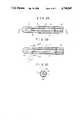
- FIG. 6shows a sectional view illustrating the above-discussed fiber for lateral beaming of the laser beam, wherein a fiber 11 is a light-transmitting fiber made of glass or plastics and constituted by a core and a clad which are different in refractive index from each other.
- the fiberis a quartz fiber having a core diameter of 400 ⁇ m and an outer clad layer diameter of 650 ⁇ m.
- a primary coating layer 12 made of a synthetic resin materialis formed on the fiber 11 over the total length thereof.
- the fiber 11 formed thereon with the primary coating layer 12is further protected by a flexible, protective outer covering jacket 13, whereby the fiber 11 is prevented from being cracked and broken.
- Synthetic resin materialssuch as vinyl resin material, nylon and Teflon are prefearbly used to form this protective outer covering jacket 13.
- a distal end of the fiber 11is formed to provide a flat surface 14 inclined at about 45° to the center line of the fiber 11, and this flat surface is polished into an optically smooth surface.
- Portions of the primary coating layer 12 and protective outer covering jacket 13are removed from a portion of the fiber 11, including the distal end which is formed into the flat surface 14 inclined at about 45° to the center line of the fiber as described above.
- the side of the distal end of the fiber 11, from which the primary coating layer 12 and protective outer covering jacket 13 are removed,is coupled to a transparent tubular member 15 of circular cross section.
- tubular member 15is blocked in a semispherical shape, and the distal end and the tubular member 15 are firmly attached to each other in an air-tight manner by an epoxy adhesive 30.
- the inclined flat surface 14 of the fiber 11is disposed in this transparent tubular member 15 such that an air layer 32 is formed between the inner surface of the tubular member 15 and the inclined flat surface 14 of the fiber 11.
- a stepped portion 18is formed at the side of the open end of the transparent tubular member 15 over the entire circumference thereof.
- a reinforcing tube 19made of a flexible material such as Teflon for protecting and reinforcing the fiber 11 substantially over the total length thereof, is solidly secured to this stepped portion by adhesive bonding, or by being enlarged in diameter due to heating and coupled onto the stepped portion, and thereafter cooled for shrinkage.
- This reinforcing tube 19is provided with an inner diameter sufficient for forming a hollow space 21 which is annular in cross section and extends between the inner peripheral surface thereof and the protective outer covering jacket 13 of the fiber 11 over the total length, and with an outer shape substantially equal to the outer shape of the transparent tubular member 15.
- the fiber for lateral beaming discussed abovefunctions very effectively when it is used together with a front-view type endoscope in a through-endoscope manner.
- the following disadvantageshave been presented by this fiber for lateral beaming.
- a thin air layeris formed between the inner wall surface of the transparent tubular member in the longitudinal direction thereof and the outer peripheral wall of the fiber, and the interface therebetween functions as a reflecting surface due to the presence of this air layer.
- a leaking beamis generated which is emitted in a direction other than aan aimed direction, particularly to a direction opposite to the aimed direction (namely in the direction of leaking).
- this leaking beamresults in burning a normal portion other than the aimed affected protion.
- Another leaking beamother than the leaking beam caused by the interface of the air layer, is generated.
- This leaking beamis directed in the forward direction of a probe. Although it depends upon the mode of propagation of the laser beam, which has fallen into the fiber, this beam is not reflected laterally, transmitted through the surface inclined at 45°, and directed forward because of the presence of an incident beam component, the incident angle of which becomes lower than a critical angle on the entirely reflecting surface.
- the latter leaking beamresults in burning a normal portion other than the aimed affected portion.
- the third problem of which the fiber for lateral beaming which has heretofore been proposed,is the problem of breakage in use. Namely, under the use conditions in a through-endoscopic manner a fiber probe is not guided rectilinearly to the aimed position in a body, rather, it is introduced to the aimed portion in the body using an endoscope tridimensionally flexed for catching the affected portion in the visual field of observation of the endoscope as a path for the insertion of the fiber probe.
- a forceps channelhaving an inner diameter of about 2 to 3 mm for introducing a forceps for the treatment.
- a radius of curvature of this forceps channel in an endoscope used at presentis fairly small, whereby an external force in a direction crossing the axial line of the fiber is applied to the forward end portion of the fiber having no flexibility when the fiber is passed through a curved portion having such a radius of curvature as described above.
- a strong external force directed along the axial lineis applied to the tubular member and therearound, a sharing force occurs at a boundary portion between a portion of the continuous fiber, which is covered by the inflexible tubular member, and a portion of the fiber, which is covered by the flexible coating layers and the flexible outer covering layer, whereby a breakage occurs at this boundary position.
- the portion of the fiberfalls down together with the tubular member and remains in the body, so that very dangerous results may be brought about.
- the forward end of the fiber probeshould be protruded forward from the forward end of the front-view type endoscope by a value commensurate to an angle of the field of observation of the endoscope. As this forward protrusion value increases, it becomes more difficult to change the degrees of flexing of the forward end portion of the endoscope and to finely adjust the direction of irradiation.
- the present inventionhas been developed to obviate the above-described drawbacks and disadvantages of the conventional fiber for lateral beaming of a laser beam, and has as its object the provision of a fiber for lateral beaming of a laser beam wherein harmful leaking beams are eliminated and breakages are avoided.
- Another object of the present inventionis to provide a fiber for lateral beaming of a laser beam wherein, when it is used together with a front-view type endoscope, the protrusion value thereof from the forward end portion of the endoscope is minimized.
- the present inventioncontemplates that, in the fiber for lateral beaming of a laser beam, a distal end thereof is formed into a surface inclined at about 35° to 40° to the center line of the fiber, a transparent tubular member, one end of which is blocked by a surface (preferably a semispherical surface) having no acute angle portion and the inner diameter of which is formed sufficiently larger than the outer diameter of the fiber, is coupled to a forward end portion of the fiber including the aforesaid inclined surface, an air layer is formed between this tubular member and the inclined surface at the forward end portion of the fiber, and an anti-reflection coating layer is deposited on one surface of the outer surfaces of the tubular member and a high reflecting layer is deposited on the other surface.
- a transparent tubular memberone end of which is blocked by a surface (preferably a semispherical surface) having no acute angle portion and the inner diameter of which is formed sufficiently larger than the outer diameter of the fiber
- the fiber for lateral beaming of a laser beam according to the present inventionis of such an arrangement that a portion of the transparent tubular member is coupled to the fiber, partially overlapping with the protective coating layers of the fiber.
- the fiber for lateral beaming of a laser beam according to the present inventionis of such an arrangement that, a flat surface parallel to the center line of the transparent tubular member is formed on a portion of the transparent tubular member, and at least a anti-reflection coating layer is deposited on this flat surface.
- the distal endis formed into the entirely reflecting surface having the inclination of 35° to 40°, a reflection preventive layer is deposited on a portion of the outer side surface of the transparent tubular member covering the fiber, and an entirely reflecting layer is deposited on the outer side surface opposite to the former outer side surface, so that the harmful leaking beam can be prevented from being generated.
- the reflection preventive layer and entirely reflecting layerare deposited on flat portions of the tubular member, so that the layers function reliably.
- the transparent tubular memberis coupled to the protective coated portion of the fiber, whereby the external force acting on the tubular member tends to be absorbed by the protective coated portion overlapping with the tubular member, so that the forward end portion of the fiber can be prevented from being broken.
- FIG. 1is a schematic diagram showing the fiber for lateral beaming of a laser beam according to the present invention, as in the use conditions;
- FIGS. 2(A), 2(B) and 2(C)are sectional views showing one embodiment of the fiber for lateral beaming of a laser beam according to the present invention
- FIG. 3shows an appearance of the fiber for lateral beaming of a laser beam shown in FIGS. 2;
- FIGS. 4(A) and 4(B)show the comparison of the protruded lengths of the forward ends of the conventional fiber for lateral beaming of a laser beam and of the fiber according to the present invention
- FIG. 5shows an appearance of another embodiment of the fiber for lateral beaming of a laser beam according to the present invention.
- FIG. 6is a sectional view showing the fiber for lateral beaming of a laser beam disclosed in Japanese Patent Application No. 187782/1984.
- FIGS. 1 to 4show one embodiment of the fiber for lateral beaming of a laser beam according to the present invention.
- a fiber for lateral beaming of a laser beam(hereinafter referred to as an "Irradiation probe") 1 is connected to a well-known laser beam source, not shown, and transmits a laser beam to a distal end.
- the irradiation probeis formed of a quartz fiber, for example, constituted by a core fiber 11 and a clad layer (Refer to FIG. 2), and the laser beam is transmitted in the probe, repeating the entire reflections.
- this irradiation probe 1is usable as it is, however, in order to treat the cavity in an internal organ in a living body and the like without resorting to laparotomy, the irradiation probe is frequently used in a through-endoscopic manner. More specifically, an observation head 2A of an endoscope 2, well known by itself, is inserted into an aimed cavity in an internal organ, and thereafter the irradiation probe 1 is introduced into the cavity through an insertion path (as indicated by an insertion opening 2B) for an instrument for the treatment, such as a forceps, the insertion path being normally provided in the endoscope.
- the distal end 1A of the irradiation probe 1 together with the observation head 2A of the endoscope 2can be adjusted in the direction of irradiation as well as the field of observation by use of a flexing adjusting knob 2C of the endoscope.
- the fiber 11 used in the fiber for lateral beaming of a laser beam according to the present inventionis made of quartz glass or plastics and is constituted by a core and a clad, which are well known and different in refractive index from each other.
- a quartz fiberis used having a core diameter of 400 ⁇ m and an outer clad layer diameter of 600 ⁇ m.
- the core diameter and outer clad layer diametermay be selected desirably in accordance with the purpose of use and the configuration.
- the irradiation probe 1is provided with a triple layer construction of coating layers over the total length of the fiber.
- a first coating layer 12is a so-called primary coating layer, formed of a silicone coating layer for example.
- a second coating jacket 13is an outer covering jacket such as a nylon tube.
- a third coating layer 16is an outer covering jacket such as a Teflon tube.
- the first and the second coating layers 12 and 13are similar to those of the conventional well-known light transmitting fiber, do not directly function as the light transmitters, and rather serve to prevent the fiber 11 from being cracked and broken.
- the third coating layer 16constitutes a part of the characteristics of the present invention, which will be described in detail hereinafter.
- the distal end of the fiber 11is formed to provide a surface 14 inclined at about 35° to 40° to the center line of the fiber 11, and the surface 14 is polished into an optically smooth surface.
- the first to the third coating layers 12, 13 and 16are removed over some length including the distal ends thereof, and the third coating layer is removed over a greater length than the other layers.
- a transparent, hollow tubular member 15, having one end thereof blocked in a generally semispherical shape and being circular in cross section,is coupled to an exposed portion of the second coating jacket 13, so as to incorporate therein an exposed portion of the fiber 11.
- An open end of the hollow tubular member 15is closely attached to the forward end of the third coating layer 16.
- the tubular member 15is formed with flat surfaces 15A and 15B, which are opposed and substantially parallel to each other. Consequently, the coating layer 16 and the tubular member 15 are substantially equal in outer diameter to each other, however, there is a slight difference in diameter at the flat surfaces 15A and 15B between the coating layer 16 and the tubular member 15.
- a heat-shrinkable tube 17is coupled onto the tubular member 15 and the third coating 16 in a manner to cover these members, and clampingly protects these members by the heat shrinking action. There is the difference in diameter at the flat surfaces 15A and 15B between these members, however, these portions are closely clamped to each other by the shrinking action of the heat shrinkable tube 17.
- a reflection preventive coating layeris deposited on the flat surface portion 15A of the tubular member 15, and a highly reflective coating layer is deposited on the flat surface portion 15B.
- the irradiation probe according to the present inventionWhen the irradiation probe according to the present invention with the above-described arrangement is connected to a laser unit, not shown, and a laser beam is generated, the laser beam is transmitted through the fiber 11 as well known, repeating the entire reflections entirely reflected by the inclined surface 14 transmitted through the transparent tubular member 15 including the flat surface 15A, and the irradiation of the laser beam L is carried out forward in a direction of about 60° to 75°.
- a reflected beamOn the flat surface 15A, a reflected beam is prevented from being generated by the reflection preventive coating layer deposited on the flat surface 15A.
- a beam reflected by another interfaceis prevented from being transmitted by the action of the highly reflective coating layer deposited on the flat surface 15B.
- a reflected beam generated at an interface due to the presence of an air layer in the tubular memberis prevented from becoming an unnecessary leaking beam and exiting in a direction other than an aimed direction by the entirely reflecting coating layer deposited on the flat surface portion 15B.
- this leaking beamcannot be completely eliminated, the leaking beam can be reduced to an extent where the thermal destruction of the normal portion can be medically, completely prevented. Consequently, it is permissible that an air layer remains between the inner surface of the tubular member 15 and the outer surface of the fiber 11. Furthermore, this makes it very easy to mount the tubular member 15 to the fiber. More specifically, it becomes unnecessary to improve the coupling accuracy between the tubular member 15 and the fiber and to perform the accuracy control strictly.
- a difference in dimension between the inner diameter and the outer diameteris substantially equal to thicknesses of the first and the second coating layers, so that the forward end of the fiber 11 can be easily inserted into the tubular member 15, without the former impinging against the latter, thus improving the working efficiency.
- the tubular member 15is not directly joined to the fiber 11 but is joined through the first and the second coating layers 12 and 13, so that even when a strong external force acts on the tubular member 15, the force is not applied to the fiber as a shearing force directly acting on the fiber. Consequently, breakages of the forward end of the fiber 11 can be avoided.
- the direction of irradiationbecomes the forward direction of about 60° to 75° to the center line of the fiber 11, whereby, as apparent from FIG. 4, the protrusion value of the irradiation probe 1 from the forward end of the endoscope is smaller as compared with one for lateral beaming at 90° (refer to FIG. 4(A)).
- the protrusion value of the irradiation probe 1 from the forward end of the endoscopeis smaller as compared with one for lateral beaming at 90° (refer to FIG. 4(A)).
- a shadowy portion relative to the irradiation beam Lmay occur.
- the endoscope itselfis inserted deeper and the observation head 2A of the endoscope is slightly curved, the same action as in the case of side irradiation at 90° can be performed.
- designated at Wis a wall surface of a cavity or the like.
- the side surface of the exiting side of the tubular member 15 and the surface opposed theretohave been formed to provide the flat surfaces 15A and 15B, respectively.
- the flat surface 15Bis dispensed with and the curved surface as is may be deposited with the highly reflective coating layer. Further, even the highly reflective coating layer may be dispensed with.
- the flat surface 15Amay be dispensed with as the case may be; however; the anti-reflection coating layer is indispensable. However, as viewed from the characteristics of the coating layer, it is all right when a uniform layer can be deposited on the curved surface.
- the layer thicknessis reduced from the center to the sides, whereby the portion which has the function as designed is limited to a very small scope about the center. Consequently, when the flat surface 15A is formed, the layer as designed is obtainable over the entire flat surface.
- the flat surface 15A formed for the above-described purposeis advantageous in specifying a position relative to the inclined surface 14 of the fiber 11 for the assembling operation of the irradiation probe. More specifically, it is very difficult to couple onto the fiber the tubular member having a length of about 9 mm and an outer diameter of about 2 mm and not having a flat surface with a coating layer deposited thereon in such a manner that the coating layer portion of the tubular member, which is difficult to discriminate visually, is made to coincide with the exiting direction of the fiber.
- the provision of the flat surfacegives the clear positional relationship therebetween, thereby facilitating assembly.
- FIG. 5shows another embodiment of the present invention. A difference between this embodiment and the first embodiment resides in the shape of the heat-shrinkable tube, and this embodiment is identical with the first embodiment in all other respects.
- the heat-shrinkable tube 27is provided at a portion thereof corresponding to the beam exiting portion of the tubular member 15 with a circular opening 28, and covers the tubular member 15 as a whole.
- the function of the heat-shrinkable tube 27 in this embodimentresides in that, when the tubular member 15 is damaged for some reason or other, broken pieces are left in the heat-shrinkable tube 27 and do not remain in the body, so that the broken pieces can be taken out of the body at once.
- the fiber for lateral beaming of a laser beamfeatures that the laser beam is introduced into a cavity in an internal organ in a living body in a through-endoscopic manner to generally frontally irradiate an affected portion, the fiber is not broken in spite of the fact that the fiber is inserted through an introducing path of an endoscope which is very thin and has a small radius of permissible flexing, and the leaking beams of the laser beam can be reduced as much as possible, so that damage to the normal portions can be avoided.
Landscapes
- Health & Medical Sciences (AREA)
- Life Sciences & Earth Sciences (AREA)
- Physics & Mathematics (AREA)
- Surgery (AREA)
- Biomedical Technology (AREA)
- Engineering & Computer Science (AREA)
- Optics & Photonics (AREA)
- Veterinary Medicine (AREA)
- Animal Behavior & Ethology (AREA)
- Nuclear Medicine, Radiotherapy & Molecular Imaging (AREA)
- Public Health (AREA)
- General Health & Medical Sciences (AREA)
- Pathology (AREA)
- Radiology & Medical Imaging (AREA)
- Heart & Thoracic Surgery (AREA)
- Molecular Biology (AREA)
- Medical Informatics (AREA)
- Biophysics (AREA)
- General Physics & Mathematics (AREA)
- Electromagnetism (AREA)
- Otolaryngology (AREA)
- Laser Surgery Devices (AREA)
- Endoscopes (AREA)
- Lasers (AREA)
- Optical Fibers, Optical Fiber Cores, And Optical Fiber Bundles (AREA)
Abstract
Description
Claims (6)
Applications Claiming Priority (2)
| Application Number | Priority Date | Filing Date | Title |
|---|---|---|---|
| JP60-61267 | 1985-03-26 | ||
| JP60061267AJP2615006B2 (en) | 1985-03-26 | 1985-03-26 | Laser beam side fiber |
Publications (1)
| Publication Number | Publication Date |
|---|---|
| US4740047Atrue US4740047A (en) | 1988-04-26 |
Family
ID=13166277
Family Applications (1)
| Application Number | Title | Priority Date | Filing Date |
|---|---|---|---|
| US06/841,422Expired - LifetimeUS4740047A (en) | 1985-03-26 | 1986-03-19 | Fiber for lateral beaming of laser beam |
Country Status (2)
| Country | Link |
|---|---|
| US (1) | US4740047A (en) |
| JP (1) | JP2615006B2 (en) |
Cited By (117)
| Publication number | Priority date | Publication date | Assignee | Title |
|---|---|---|---|---|
| US4778247A (en)* | 1984-05-04 | 1988-10-18 | Warner Lambert Technologies, Inc. | Molded objective head for fiberscopes with integral lenses |
| US4842390A (en)* | 1987-07-17 | 1989-06-27 | Consiglio Nazionale Delle Ricerche | Fiber optic device for angioplasty |
| US4842356A (en)* | 1987-04-15 | 1989-06-27 | Kei Mori | Light ray radiation device for use in medical treatment of the nose and throat passages |
| US4930851A (en)* | 1988-06-07 | 1990-06-05 | Mitsubishi Kasei Corporation | Image magnifying and pick-up system with lighting light-guide device |
| FR2642183A1 (en)* | 1989-01-24 | 1990-07-27 | Schott Glaswerke | OPTICAL FIBER FOR RADIATION IRRADIATION OF HOLLOW SYSTEMS IN THE FORM OF TUBES WITH LASER RAYS |
| US4985029A (en)* | 1989-01-11 | 1991-01-15 | Masahiko Hoshino | Laser apparatus for medical treatment |
| US4986628A (en)* | 1988-08-23 | 1991-01-22 | Lozhenko Alexandr S | Light guide device for phototherapy |
| US4994060A (en)* | 1984-09-17 | 1991-02-19 | Xintec Corporation | Laser heated cautery cap with transparent substrate |
| DE3941706C1 (en)* | 1989-12-18 | 1991-02-28 | Gesellschaft Fuer Strahlen- Und Umweltforschung Mbh, 8042 Neuherberg, De | |
| EP0374243A4 (en)* | 1988-06-10 | 1991-03-13 | Trimedyne Laser Systems, Inc. | Medical device applying localized high intensity light and heat, particularly for destruction of the endometrium |
| US5011279A (en)* | 1987-06-13 | 1991-04-30 | Basf Aktiengesellschaft | Fiber-optical sensor |
| US5061265A (en)* | 1989-06-20 | 1991-10-29 | University Of Florida | Laser treatment apparatus and method |
| WO1991017793A1 (en)* | 1990-05-16 | 1991-11-28 | Sunrise Technologies, Inc. | Optical fiber probe and laser sclerostomy procedure |
| US5147353A (en)* | 1990-03-23 | 1992-09-15 | Myriadlase, Inc. | Medical method for applying high energy light and heat for gynecological sterilization procedures |
| WO1992017138A3 (en)* | 1991-04-04 | 1992-11-12 | Premier Laser Systems Inc | Laser surgical probe |
| US5163935A (en)* | 1991-02-20 | 1992-11-17 | Reliant Laser Corporation | Surgical laser endoscopic focusing guide with an optical fiber link |
| US5188634A (en)* | 1990-07-13 | 1993-02-23 | Trimedyne, Inc. | Rotatable laser probe with beveled tip |
| FR2681522A1 (en)* | 1991-09-24 | 1993-03-26 | Charron Jean Yves | Device for treating a lesion inside the body of a patient |
| US5242437A (en)* | 1988-06-10 | 1993-09-07 | Trimedyne Laser Systems, Inc. | Medical device applying localized high intensity light and heat, particularly for destruction of the endometrium |
| US5250045A (en)* | 1991-06-11 | 1993-10-05 | The Spectranetics Corporation | Optical fiber catheter with spaced optical fiber |
| US5253312A (en)* | 1992-06-26 | 1993-10-12 | Cytocare, Inc. | Optical fiber tip for use in a laser delivery system and a method for forming same |
| US5267996A (en)* | 1990-11-15 | 1993-12-07 | Laserscope | Laser surgery aspiration apparatus and technique |
| US5292320A (en)* | 1992-07-06 | 1994-03-08 | Ceramoptec, Inc. | Radial medical laser delivery device |
| US5304167A (en)* | 1988-11-10 | 1994-04-19 | Premier Laser Systems, Inc. | Multiwavelength medical laser method |
| US5322507A (en)* | 1992-08-11 | 1994-06-21 | Myriadlase, Inc. | Endoscope for treatment of prostate |
| US5343543A (en)* | 1993-05-27 | 1994-08-30 | Heraeus Surgical, Inc. | Side-firing laser fiber with directional indicator and methods of use in determining the orientation of radiation to be emitted from the side-firing laser fiber |
| FR2702662A1 (en)* | 1993-03-15 | 1994-09-23 | Alliance Tech Ind | Fiber optic medical probe. |
| US5354294A (en)* | 1993-05-26 | 1994-10-11 | Xintec Corporation | Combination reflectance fiber optic laser beam angle delivery |
| US5385572A (en)* | 1992-11-12 | 1995-01-31 | Beowulf Holdings | Trocar for endoscopic surgery |
| WO1995008949A1 (en)* | 1993-09-29 | 1995-04-06 | Medical College Of Ohio | Use of photodynamic therapy to treat prostatic tissue |
| EP0610991A3 (en)* | 1993-02-08 | 1995-04-19 | Xintec Corp | Device for laser assisted transurethral resection of the prostate(TURP). |
| US5416878A (en)* | 1993-07-29 | 1995-05-16 | Endeavor Surgical Products, Inc. | Surgical methods and apparatus using a bent-tip side-firing laser fiber |
| US5428699A (en)* | 1993-07-02 | 1995-06-27 | Laserscope | Probe having optical fiber for laterally directing laser beam |
| US5432811A (en)* | 1993-03-04 | 1995-07-11 | Tecnal Products, Inc. | Laser rod with polyhedron shaped ends |
| US5449356A (en)* | 1991-10-18 | 1995-09-12 | Birtcher Medical Systems, Inc. | Multifunctional probe for minimally invasive surgery |
| US5451221A (en)* | 1993-12-27 | 1995-09-19 | Cynosure, Inc. | Endoscopic light delivery system |
| EP0673627A1 (en)* | 1994-03-23 | 1995-09-27 | Yasuo Hashimoto | Catheter with optical fiber |
| US5464404A (en)* | 1993-09-20 | 1995-11-07 | Abela Laser Systems, Inc. | Cardiac ablation catheters and method |
| US5476461A (en)* | 1994-05-13 | 1995-12-19 | Cynosure, Inc. | Endoscopic light delivery system |
| US5487740A (en)* | 1994-03-02 | 1996-01-30 | Energy Life Systems Corporation | Laser device for ablation of human tissue |
| US5495541A (en)* | 1994-04-19 | 1996-02-27 | Murray; Steven C. | Optical delivery device with high numerical aperture curved waveguide |
| US5496309A (en)* | 1994-05-06 | 1996-03-05 | Trimedyne, Inc. | Catheter device utilizing a laser beam laterally directed by a high index prism in a liquid medium |
| US5502784A (en)* | 1994-07-01 | 1996-03-26 | Valquest Medical, Inc. | Heat insulating connector for plastic optical fibers |
| US5509917A (en)* | 1994-06-28 | 1996-04-23 | Ceramoptec Industries, Inc. | Lensed caps for radial medical laser delivery devices |
| WO1996018347A1 (en)* | 1994-12-14 | 1996-06-20 | Lee Brine | Optical fibre laser delivery probe and use thereof |
| US5537499A (en)* | 1994-08-18 | 1996-07-16 | Laser Peripherals, Inc. | Side-firing laser optical fiber probe and method of making same |
| US5548674A (en)* | 1989-08-29 | 1996-08-20 | Fibotech, Inc. | High precision fiberoptic alignment spring receptacle and fiberoptic probe |
| US5554112A (en)* | 1992-10-09 | 1996-09-10 | Birtcher Medical Systems, Inc. | Minimally invasive irrigator/aspirator surgical probe and method of using same |
| US5554153A (en)* | 1994-08-29 | 1996-09-10 | Cell Robotics, Inc. | Laser skin perforator |
| US5562657A (en)* | 1994-09-19 | 1996-10-08 | Griffin; Stephen E. | Side fire laser catheter method and apparatus |
| US5562696A (en)* | 1992-11-12 | 1996-10-08 | Cordis Innovasive Systems, Inc. | Visualization trocar |
| US5579423A (en)* | 1994-08-03 | 1996-11-26 | Lederle (Japan), Ltd. | Optical fiber laser device |
| WO1996039962A1 (en)* | 1995-06-07 | 1996-12-19 | Cardiogenesis Corporation | Optical probe for myocardial channel formation |
| US5651785A (en)* | 1993-09-20 | 1997-07-29 | Abela Laser Systems, Inc. | Optical fiber catheter and method |
| US5651786A (en)* | 1993-09-20 | 1997-07-29 | Abela Laser Systems, Inc. | Mapping catheter and method |
| US5688261A (en)* | 1990-11-07 | 1997-11-18 | Premier Laser Systems, Inc. | Transparent laser surgical probe |
| USRE35734E (en)* | 1989-10-31 | 1998-02-17 | Fibotech, Inc. | Metal core fiberoptic connector plug for single fiber and multiple fiber coupling |
| US5722970A (en)* | 1991-04-04 | 1998-03-03 | Premier Laser Systems, Inc. | Laser surgical method using transparent probe |
| US5746737A (en)* | 1995-06-07 | 1998-05-05 | Trimedyne, Inc. | Enclosure for a lasing device |
| US5772657A (en)* | 1995-04-24 | 1998-06-30 | Coherent, Inc. | Side firing fiber optic laser probe |
| US5772658A (en)* | 1994-12-20 | 1998-06-30 | Laser Industries, Ltd. | Side-emitting optical fibers for lasers |
| US5782824A (en)* | 1993-09-20 | 1998-07-21 | Abela Laser Systems, Inc. | Cardiac catheter anchoring |
| US5807389A (en)* | 1991-08-16 | 1998-09-15 | Myriadlase, Inc. | Laterally reflecting tip for laser transmitting fiber |
| US5833683A (en)* | 1996-01-12 | 1998-11-10 | Surgical Laser Technologies, Inc. | Laterally-emitting laser medical device |
| US5836941A (en)* | 1993-09-07 | 1998-11-17 | Olympus Optical Co., Ltd. | Laser probe |
| US5897551A (en)* | 1990-03-23 | 1999-04-27 | Myriadlase, Inc. | Medical device for applying high energy light and heat for gynecological sterilization procedures |
| USRE36231E (en)* | 1989-10-31 | 1999-06-22 | Fibotech, Inc. | Fiberoptic connector assembly and method and device for the manufacture thereof |
| US5921916A (en)* | 1994-07-07 | 1999-07-13 | Ueth & Haug Gmbh | Endoscope utilizing a fiber optic holding tube with a jacket slit for lateral placement of the fiber optic |
| US6029671A (en)* | 1991-07-16 | 2000-02-29 | Heartport, Inc. | System and methods for performing endovascular procedures |
| US20020108610A1 (en)* | 1996-02-26 | 2002-08-15 | Christopher Kent L. | Method and apparatus for endotracheal intubation using a light wand and curved guide |
| US20030236453A1 (en)* | 2002-06-19 | 2003-12-25 | Simon Furnish | Multi-channel catheter tip |
| US20040017961A1 (en)* | 2002-07-25 | 2004-01-29 | Petersen Christopher L. | Scanning miniature optical probes with optical distortion correction and rotational control |
| US20040254478A1 (en)* | 2003-05-22 | 2004-12-16 | De Josselin De Jong Elbert | Fluorescence filter for tissue examination and imaging |
| US20040254567A1 (en)* | 2003-02-12 | 2004-12-16 | Holz Frank G. | Surgical method for ablating tissue |
| US20060129210A1 (en)* | 2004-11-09 | 2006-06-15 | Institut National D'optique | Device and method for transmitting multiple optically-encoded stimulation signals to multiple cell locations |
| US20070005121A1 (en)* | 2002-04-29 | 2007-01-04 | Rohit Khanna | Central nervous system cooling catheter |
| US20070106286A1 (en)* | 2005-11-10 | 2007-05-10 | Ceramoptec Industries, Inc. | Side fire optical fiber for high power applications |
| US20080188843A1 (en)* | 2002-07-10 | 2008-08-07 | Appling William M | Device and method for endovascular treatment for causing closure of a blood vessel |
| US20080287936A1 (en)* | 2007-05-18 | 2008-11-20 | Stinson Douglas G | Telescope with Integrated Optical Filter |
| US20090287199A1 (en)* | 2008-05-19 | 2009-11-19 | Brian Hanley | Side-firing laser fiber with protective tip and related methods |
| US20090326525A1 (en)* | 2008-06-26 | 2009-12-31 | Jessica Hixon | Laser fiber capillary apparatus and method |
| US20100016845A1 (en)* | 2008-05-19 | 2010-01-21 | Brian Hanley | Method and apparatus for protecting capillary of laser fiber during insertion and reducing metal cap degradation |
| US20100135617A1 (en)* | 2008-12-01 | 2010-06-03 | Ams Research Corporation | Optical device |
| DE102008064576A1 (en) | 2008-12-22 | 2010-07-01 | Fibertech Gmbh | Laterally radiating laser fiber for use in e.g. gynecology for tissue removal, has quartz cap rotated by rotating sleeve, where rotating sleeve is fastened to polyethylene ether ketone flexible tube attached to coating of fiber |
| EP2254495A1 (en) | 2008-02-28 | 2010-12-01 | CeramOptec GmbH | Endoluminal laser ablation device and method for treating veins |
| US20110002584A1 (en)* | 2006-12-07 | 2011-01-06 | Ams Research Corporation | Annular side fire optical device for laterally redirecting electromagnetic radiation |
| US20110149589A1 (en)* | 2008-07-30 | 2011-06-23 | Ams Research Corporation | Optical device having fluorocarbon polymer layer |
| US20110152619A1 (en)* | 2009-12-17 | 2011-06-23 | Boston Scientific Scimed, Inc. | Methods and apparatus related to an optical fiber member having a removable cover |
| US20110176772A1 (en)* | 2009-11-18 | 2011-07-21 | Jessica Hixon | Methods and apparatus related to a distal end of a side-fire optical fiber having multiple capillary components |
| US20110206321A1 (en)* | 2010-02-22 | 2011-08-25 | Boston Scientific Scimed, Inc. | Methods and apparatus related to a side-fire optical fiber having a robust distal end portion |
| US20110230872A1 (en)* | 2005-06-08 | 2011-09-22 | Ams Research Corporation | Lateral Laser Fiber for High Average Power and Peak Pulse Energy |
| CN103239210A (en)* | 2013-05-07 | 2013-08-14 | 深圳市中科微光医疗器械技术有限公司 | Ultra-miniature optical coherence tomography probe for eliminating interference rings |
| US8781275B2 (en) | 2010-07-27 | 2014-07-15 | Boston Scientific Scimed, Inc. | Laser assembly with shock absorber |
| US8915948B2 (en) | 2002-06-19 | 2014-12-23 | Palomar Medical Technologies, Llc | Method and apparatus for photothermal treatment of tissue at depth |
| US20150094698A1 (en)* | 2003-11-07 | 2015-04-02 | Visualase, Inc. | Cooled Laser Fiber for Improved Thermal Therapy |
| US9028536B2 (en) | 2006-08-02 | 2015-05-12 | Cynosure, Inc. | Picosecond laser apparatus and methods for its operation and use |
| CN105286995A (en)* | 2014-06-25 | 2016-02-03 | 黎富尧 | Side-lit optical fiber for photodynamic therapy of prostatic diseases |
| US20160079810A1 (en)* | 2014-09-12 | 2016-03-17 | The Government Of The United States Of America, As Represented By The Secretary Of The Navy | Photovoltaics optimized for laser remote power applications at eye-safer wavelengths |
| US9323005B1 (en) | 2014-12-22 | 2016-04-26 | InnovaQuartz LLC | Redirecting electromagnetic radiation |
| US9488782B2 (en) | 2014-12-22 | 2016-11-08 | InnovaQuartz LLC | Redirecting electromagnetic radiation |
| US9618700B1 (en) | 2015-12-03 | 2017-04-11 | InnovaQuartz LLC | Orthogonal output optical fiber |
| US9662173B1 (en) | 2015-12-24 | 2017-05-30 | Cyclone Biosciences LLC | Lateral delivery device with active cooling |
| US9780518B2 (en) | 2012-04-18 | 2017-10-03 | Cynosure, Inc. | Picosecond laser apparatus and methods for treating target tissues with same |
| US9782562B2 (en) | 2002-04-04 | 2017-10-10 | Angiodynamics, Inc. | Venous insufficiency treatment method |
| US9814513B2 (en) | 2011-06-30 | 2017-11-14 | Angiodynamics, Inc. | Endovascular plasma treatment device and method of use |
| US10092356B2 (en) | 2015-11-18 | 2018-10-09 | InnovaQuartz LLC | Radial emissions from optical fibers |
| US10245107B2 (en) | 2013-03-15 | 2019-04-02 | Cynosure, Inc. | Picosecond optical radiation systems and methods of use |
| US10434324B2 (en) | 2005-04-22 | 2019-10-08 | Cynosure, Llc | Methods and systems for laser treatment using non-uniform output beam |
| US10433909B2 (en) | 2007-07-18 | 2019-10-08 | Visualase, Inc. | Systems and methods for thermal therapy |
| US10849506B2 (en) | 2016-04-13 | 2020-12-01 | Inspektor Research Systems B.V. | Bi-frequency dental examination |
| US11172821B2 (en) | 2016-04-28 | 2021-11-16 | Medtronic Navigation, Inc. | Navigation and local thermometry |
| US11418000B2 (en) | 2018-02-26 | 2022-08-16 | Cynosure, Llc | Q-switched cavity dumped sub-nanosecond laser |
| US11576724B2 (en) | 2011-02-24 | 2023-02-14 | Eximo Medical Ltd. | Hybrid catheter for vascular intervention |
| US11684420B2 (en) | 2016-05-05 | 2023-06-27 | Eximo Medical Ltd. | Apparatus and methods for resecting and/or ablating an undesired tissue |
| US11826097B2 (en) | 2015-11-18 | 2023-11-28 | Cyclone Biosciences, Llc | Forming radial emissions from optical fibers |
| US12038322B2 (en) | 2022-06-21 | 2024-07-16 | Eximo Medical Ltd. | Devices and methods for testing ablation systems |
| US12376904B1 (en) | 2020-09-08 | 2025-08-05 | Angiodynamics, Inc. | Dynamic laser stabilization and calibration system |
Families Citing this family (5)
| Publication number | Priority date | Publication date | Assignee | Title |
|---|---|---|---|---|
| JPS6426708U (en)* | 1987-08-06 | 1989-02-15 | ||
| JP4637327B2 (en)* | 2000-07-03 | 2011-02-23 | テルモ株式会社 | Heat treatment device |
| WO2007112196A2 (en)* | 2006-03-23 | 2007-10-04 | Medeikon Corporation | Low reflection lateral output fiber probe |
| US7507038B2 (en)* | 2007-04-03 | 2009-03-24 | Mitsubishi Cable Industries, Ltd. | Optical fiber/glass tube fusion-spliced structure, optical fiber assembly including the structure, and glass tube used in the structure |
| JP5681964B1 (en)* | 2014-04-15 | 2015-03-11 | 直樹 榊原 | Light control unit and energy irradiation device for energy device |
Citations (5)
| Publication number | Priority date | Publication date | Assignee | Title |
|---|---|---|---|---|
| US2797683A (en)* | 1954-11-29 | 1957-07-02 | Thomas F Aiken | Bronchoscope with illuminating system |
| US4224929A (en)* | 1977-11-08 | 1980-09-30 | Olympus Optical Co., Ltd. | Endoscope with expansible cuff member and operation section |
| US4567882A (en)* | 1982-12-06 | 1986-02-04 | Vanderbilt University | Method for locating the illuminated tip of an endotracheal tube |
| US4576147A (en)* | 1981-07-16 | 1986-03-18 | Olympus Optical Co., Ltd. | Hard endoscope with improved light dispersion |
| JPS6164242A (en)* | 1984-09-07 | 1986-04-02 | 橋本 大定 | Laser beam side beam fiber |
Family Cites Families (5)
| Publication number | Priority date | Publication date | Assignee | Title |
|---|---|---|---|---|
| JPS4730237U (en)* | 1971-04-22 | 1972-12-06 | ||
| JPS5532872U (en)* | 1978-08-22 | 1980-03-03 | ||
| JPS5917289U (en)* | 1982-07-27 | 1984-02-02 | 三井造船株式会社 | Pump operation alarm device |
| JPS5971009A (en)* | 1982-10-18 | 1984-04-21 | Alps Electric Co Ltd | Optical fiber sensor |
| JPS59133506A (en)* | 1983-01-20 | 1984-07-31 | Olympus Optical Co Ltd | Optical quartz fiber for transmitting laser light |
- 1985
- 1985-03-26JPJP60061267Apatent/JP2615006B2/ennot_activeExpired - Fee Related
- 1986
- 1986-03-19USUS06/841,422patent/US4740047A/ennot_activeExpired - Lifetime
Patent Citations (5)
| Publication number | Priority date | Publication date | Assignee | Title |
|---|---|---|---|---|
| US2797683A (en)* | 1954-11-29 | 1957-07-02 | Thomas F Aiken | Bronchoscope with illuminating system |
| US4224929A (en)* | 1977-11-08 | 1980-09-30 | Olympus Optical Co., Ltd. | Endoscope with expansible cuff member and operation section |
| US4576147A (en)* | 1981-07-16 | 1986-03-18 | Olympus Optical Co., Ltd. | Hard endoscope with improved light dispersion |
| US4567882A (en)* | 1982-12-06 | 1986-02-04 | Vanderbilt University | Method for locating the illuminated tip of an endotracheal tube |
| JPS6164242A (en)* | 1984-09-07 | 1986-04-02 | 橋本 大定 | Laser beam side beam fiber |
Cited By (188)
| Publication number | Priority date | Publication date | Assignee | Title |
|---|---|---|---|---|
| US4778247A (en)* | 1984-05-04 | 1988-10-18 | Warner Lambert Technologies, Inc. | Molded objective head for fiberscopes with integral lenses |
| US4994060A (en)* | 1984-09-17 | 1991-02-19 | Xintec Corporation | Laser heated cautery cap with transparent substrate |
| US4842356A (en)* | 1987-04-15 | 1989-06-27 | Kei Mori | Light ray radiation device for use in medical treatment of the nose and throat passages |
| US5011279A (en)* | 1987-06-13 | 1991-04-30 | Basf Aktiengesellschaft | Fiber-optical sensor |
| US4842390A (en)* | 1987-07-17 | 1989-06-27 | Consiglio Nazionale Delle Ricerche | Fiber optic device for angioplasty |
| US4930851A (en)* | 1988-06-07 | 1990-06-05 | Mitsubishi Kasei Corporation | Image magnifying and pick-up system with lighting light-guide device |
| EP0374243A4 (en)* | 1988-06-10 | 1991-03-13 | Trimedyne Laser Systems, Inc. | Medical device applying localized high intensity light and heat, particularly for destruction of the endometrium |
| US5380317A (en)* | 1988-06-10 | 1995-01-10 | Trimedyne Laser Systems, Inc. | Medical device applying localized high intensity light and heat, particularly for destruction of the endometrium |
| US5242437A (en)* | 1988-06-10 | 1993-09-07 | Trimedyne Laser Systems, Inc. | Medical device applying localized high intensity light and heat, particularly for destruction of the endometrium |
| US5649924A (en)* | 1988-06-10 | 1997-07-22 | Trimedyne, Inc. | Medical device for irradiation of tissue |
| US4986628A (en)* | 1988-08-23 | 1991-01-22 | Lozhenko Alexandr S | Light guide device for phototherapy |
| US5304167A (en)* | 1988-11-10 | 1994-04-19 | Premier Laser Systems, Inc. | Multiwavelength medical laser method |
| US5540676A (en)* | 1988-11-10 | 1996-07-30 | Premier Laser Systems, Inc. | Method of laser surgery using multiple wavelengths |
| US4985029A (en)* | 1989-01-11 | 1991-01-15 | Masahiko Hoshino | Laser apparatus for medical treatment |
| FR2642183A1 (en)* | 1989-01-24 | 1990-07-27 | Schott Glaswerke | OPTICAL FIBER FOR RADIATION IRRADIATION OF HOLLOW SYSTEMS IN THE FORM OF TUBES WITH LASER RAYS |
| US5061265A (en)* | 1989-06-20 | 1991-10-29 | University Of Florida | Laser treatment apparatus and method |
| US5548674A (en)* | 1989-08-29 | 1996-08-20 | Fibotech, Inc. | High precision fiberoptic alignment spring receptacle and fiberoptic probe |
| USRE35734E (en)* | 1989-10-31 | 1998-02-17 | Fibotech, Inc. | Metal core fiberoptic connector plug for single fiber and multiple fiber coupling |
| USRE36231E (en)* | 1989-10-31 | 1999-06-22 | Fibotech, Inc. | Fiberoptic connector assembly and method and device for the manufacture thereof |
| FR2656115A1 (en)* | 1989-12-18 | 1991-06-21 | Strahlen Umweltforsch Gmbh | DEVICE FOR ENDING AN ISOTROPIC TRANSMITTING AND RECEIVING LIGHT GUIDE. |
| DE3941706C1 (en)* | 1989-12-18 | 1991-02-28 | Gesellschaft Fuer Strahlen- Und Umweltforschung Mbh, 8042 Neuherberg, De | |
| US5147353A (en)* | 1990-03-23 | 1992-09-15 | Myriadlase, Inc. | Medical method for applying high energy light and heat for gynecological sterilization procedures |
| US5897551A (en)* | 1990-03-23 | 1999-04-27 | Myriadlase, Inc. | Medical device for applying high energy light and heat for gynecological sterilization procedures |
| WO1991017793A1 (en)* | 1990-05-16 | 1991-11-28 | Sunrise Technologies, Inc. | Optical fiber probe and laser sclerostomy procedure |
| US5129895A (en)* | 1990-05-16 | 1992-07-14 | Sunrise Technologies, Inc. | Laser sclerostomy procedure |
| US5431646A (en)* | 1990-05-16 | 1995-07-11 | Sunrise Technologies | Optical fiber probe and laser sclerostomy procedure |
| US5188634A (en)* | 1990-07-13 | 1993-02-23 | Trimedyne, Inc. | Rotatable laser probe with beveled tip |
| US6620154B1 (en) | 1990-11-07 | 2003-09-16 | Lares Research | Laser surgical probe |
| US5688261A (en)* | 1990-11-07 | 1997-11-18 | Premier Laser Systems, Inc. | Transparent laser surgical probe |
| US5267996A (en)* | 1990-11-15 | 1993-12-07 | Laserscope | Laser surgery aspiration apparatus and technique |
| US5163935A (en)* | 1991-02-20 | 1992-11-17 | Reliant Laser Corporation | Surgical laser endoscopic focusing guide with an optical fiber link |
| US5722970A (en)* | 1991-04-04 | 1998-03-03 | Premier Laser Systems, Inc. | Laser surgical method using transparent probe |
| WO1992017138A3 (en)* | 1991-04-04 | 1992-11-12 | Premier Laser Systems Inc | Laser surgical probe |
| US5250045A (en)* | 1991-06-11 | 1993-10-05 | The Spectranetics Corporation | Optical fiber catheter with spaced optical fiber |
| WO1994002076A1 (en)* | 1991-06-11 | 1994-02-03 | The Spectranetics Corporation | A laser catheter with spaced optical fibers |
| US6029671A (en)* | 1991-07-16 | 2000-02-29 | Heartport, Inc. | System and methods for performing endovascular procedures |
| US5807389A (en)* | 1991-08-16 | 1998-09-15 | Myriadlase, Inc. | Laterally reflecting tip for laser transmitting fiber |
| FR2681522A1 (en)* | 1991-09-24 | 1993-03-26 | Charron Jean Yves | Device for treating a lesion inside the body of a patient |
| US5449356A (en)* | 1991-10-18 | 1995-09-12 | Birtcher Medical Systems, Inc. | Multifunctional probe for minimally invasive surgery |
| US5253312A (en)* | 1992-06-26 | 1993-10-12 | Cytocare, Inc. | Optical fiber tip for use in a laser delivery system and a method for forming same |
| US5496308A (en)* | 1992-07-06 | 1996-03-05 | Brown; Joseph | Radial laser delivery device |
| US5292320A (en)* | 1992-07-06 | 1994-03-08 | Ceramoptec, Inc. | Radial medical laser delivery device |
| US5322507A (en)* | 1992-08-11 | 1994-06-21 | Myriadlase, Inc. | Endoscope for treatment of prostate |
| US5593404A (en)* | 1992-08-11 | 1997-01-14 | Myriadlase, Inc. | Method of treatment of prostate |
| US5554112A (en)* | 1992-10-09 | 1996-09-10 | Birtcher Medical Systems, Inc. | Minimally invasive irrigator/aspirator surgical probe and method of using same |
| US5562696A (en)* | 1992-11-12 | 1996-10-08 | Cordis Innovasive Systems, Inc. | Visualization trocar |
| US5797944A (en)* | 1992-11-12 | 1998-08-25 | Ethicon Endo-Surgery, Inc. | Visualization trocar |
| US5385572A (en)* | 1992-11-12 | 1995-01-31 | Beowulf Holdings | Trocar for endoscopic surgery |
| US5486171A (en)* | 1993-02-08 | 1996-01-23 | Xintec Corporation | Transparent cap fiber optica laser beam angle delivery device |
| EP0610991A3 (en)* | 1993-02-08 | 1995-04-19 | Xintec Corp | Device for laser assisted transurethral resection of the prostate(TURP). |
| US5432811A (en)* | 1993-03-04 | 1995-07-11 | Tecnal Products, Inc. | Laser rod with polyhedron shaped ends |
| FR2702662A1 (en)* | 1993-03-15 | 1994-09-23 | Alliance Tech Ind | Fiber optic medical probe. |
| US5354294A (en)* | 1993-05-26 | 1994-10-11 | Xintec Corporation | Combination reflectance fiber optic laser beam angle delivery |
| US5343543A (en)* | 1993-05-27 | 1994-08-30 | Heraeus Surgical, Inc. | Side-firing laser fiber with directional indicator and methods of use in determining the orientation of radiation to be emitted from the side-firing laser fiber |
| US5428699A (en)* | 1993-07-02 | 1995-06-27 | Laserscope | Probe having optical fiber for laterally directing laser beam |
| US5416878A (en)* | 1993-07-29 | 1995-05-16 | Endeavor Surgical Products, Inc. | Surgical methods and apparatus using a bent-tip side-firing laser fiber |
| US5836941A (en)* | 1993-09-07 | 1998-11-17 | Olympus Optical Co., Ltd. | Laser probe |
| US5651786A (en)* | 1993-09-20 | 1997-07-29 | Abela Laser Systems, Inc. | Mapping catheter and method |
| US5575787A (en)* | 1993-09-20 | 1996-11-19 | Abela Laser Systems, Inc. | Cardiac ablation catheters and method |
| US5782824A (en)* | 1993-09-20 | 1998-07-21 | Abela Laser Systems, Inc. | Cardiac catheter anchoring |
| US5464404A (en)* | 1993-09-20 | 1995-11-07 | Abela Laser Systems, Inc. | Cardiac ablation catheters and method |
| US5651785A (en)* | 1993-09-20 | 1997-07-29 | Abela Laser Systems, Inc. | Optical fiber catheter and method |
| WO1995008949A1 (en)* | 1993-09-29 | 1995-04-06 | Medical College Of Ohio | Use of photodynamic therapy to treat prostatic tissue |
| US5514669A (en)* | 1993-09-29 | 1996-05-07 | Medical College Of Ohio | Use of photodynamic therapy to treat prostatic tissue |
| US5451221A (en)* | 1993-12-27 | 1995-09-19 | Cynosure, Inc. | Endoscopic light delivery system |
| US5487740A (en)* | 1994-03-02 | 1996-01-30 | Energy Life Systems Corporation | Laser device for ablation of human tissue |
| EP0673627A1 (en)* | 1994-03-23 | 1995-09-27 | Yasuo Hashimoto | Catheter with optical fiber |
| US6152951A (en)* | 1994-03-23 | 2000-11-28 | Hamamatsu Photonics K.K. | Method of treating cancer |
| US6283957B1 (en) | 1994-03-23 | 2001-09-04 | Hamamatsu Photonics K.K. | Cancer therapeutic instrument |
| US5495541A (en)* | 1994-04-19 | 1996-02-27 | Murray; Steven C. | Optical delivery device with high numerical aperture curved waveguide |
| US5496309A (en)* | 1994-05-06 | 1996-03-05 | Trimedyne, Inc. | Catheter device utilizing a laser beam laterally directed by a high index prism in a liquid medium |
| US5700260A (en)* | 1994-05-13 | 1997-12-23 | Cynosure, Inc. | Endoscopic light delivery system |
| US5476461A (en)* | 1994-05-13 | 1995-12-19 | Cynosure, Inc. | Endoscopic light delivery system |
| US5509917A (en)* | 1994-06-28 | 1996-04-23 | Ceramoptec Industries, Inc. | Lensed caps for radial medical laser delivery devices |
| US5502784A (en)* | 1994-07-01 | 1996-03-26 | Valquest Medical, Inc. | Heat insulating connector for plastic optical fibers |
| US5921916A (en)* | 1994-07-07 | 1999-07-13 | Ueth & Haug Gmbh | Endoscope utilizing a fiber optic holding tube with a jacket slit for lateral placement of the fiber optic |
| US5579423A (en)* | 1994-08-03 | 1996-11-26 | Lederle (Japan), Ltd. | Optical fiber laser device |
| US5537499A (en)* | 1994-08-18 | 1996-07-16 | Laser Peripherals, Inc. | Side-firing laser optical fiber probe and method of making same |
| US5908416A (en)* | 1994-08-29 | 1999-06-01 | Cell Robotics, Inc. | Laser dermal perforator |
| US5554153A (en)* | 1994-08-29 | 1996-09-10 | Cell Robotics, Inc. | Laser skin perforator |
| US5562657A (en)* | 1994-09-19 | 1996-10-08 | Griffin; Stephen E. | Side fire laser catheter method and apparatus |
| WO1996018347A1 (en)* | 1994-12-14 | 1996-06-20 | Lee Brine | Optical fibre laser delivery probe and use thereof |
| US5772658A (en)* | 1994-12-20 | 1998-06-30 | Laser Industries, Ltd. | Side-emitting optical fibers for lasers |
| US5772657A (en)* | 1995-04-24 | 1998-06-30 | Coherent, Inc. | Side firing fiber optic laser probe |
| US6039727A (en)* | 1995-06-07 | 2000-03-21 | Cardiogenesis Corporation | Channel forming device with penetration limiter |
| US5728091A (en)* | 1995-06-07 | 1998-03-17 | Cardiogenesis Corporation | Optical fiber for myocardial channel formation |
| US5746737A (en)* | 1995-06-07 | 1998-05-05 | Trimedyne, Inc. | Enclosure for a lasing device |
| WO1996039962A1 (en)* | 1995-06-07 | 1996-12-19 | Cardiogenesis Corporation | Optical probe for myocardial channel formation |
| US5833683A (en)* | 1996-01-12 | 1998-11-10 | Surgical Laser Technologies, Inc. | Laterally-emitting laser medical device |
| US6860264B2 (en)* | 1996-02-26 | 2005-03-01 | Evergreen Medical Incorporated | Method and apparatus for endotracheal intubation using a light wand and curved guide |
| US20020108610A1 (en)* | 1996-02-26 | 2002-08-15 | Christopher Kent L. | Method and apparatus for endotracheal intubation using a light wand and curved guide |
| US9782562B2 (en) | 2002-04-04 | 2017-10-10 | Angiodynamics, Inc. | Venous insufficiency treatment method |
| US8123789B2 (en) | 2002-04-29 | 2012-02-28 | Rohit Khanna | Central nervous system cooling catheter |
| US20070005121A1 (en)* | 2002-04-29 | 2007-01-04 | Rohit Khanna | Central nervous system cooling catheter |
| US10556123B2 (en) | 2002-06-19 | 2020-02-11 | Palomar Medical Technologies, Llc | Method and apparatus for treatment of cutaneous and subcutaneous conditions |
| US10500413B2 (en) | 2002-06-19 | 2019-12-10 | Palomar Medical Technologies, Llc | Method and apparatus for treatment of cutaneous and subcutaneous conditions |
| US8915948B2 (en) | 2002-06-19 | 2014-12-23 | Palomar Medical Technologies, Llc | Method and apparatus for photothermal treatment of tissue at depth |
| US7672713B2 (en) | 2002-06-19 | 2010-03-02 | Infraredx, Inc. | Multi-channel catheter tip |
| US8280495B2 (en) | 2002-06-19 | 2012-10-02 | Infraredx, Inc. | Multi-channel catheter tip |
| US20030236453A1 (en)* | 2002-06-19 | 2003-12-25 | Simon Furnish | Multi-channel catheter tip |
| US20100217131A1 (en)* | 2002-06-19 | 2010-08-26 | Infraredx, Inc. | Multi-channel catheter tip |
| US10238453B2 (en) | 2002-07-10 | 2019-03-26 | Angiodynamics, Inc. | Method of making an endovascular laser treatment device for causing closure of a blood vessel |
| US8864755B2 (en) | 2002-07-10 | 2014-10-21 | Angiodynamics, Inc. | Device and method for endovascular treatment for causing closure of a blood vessel |
| US8864754B2 (en) | 2002-07-10 | 2014-10-21 | Angiodynamics, Inc. | Device and method for endovascular treatment for causing closure of a blood vessel |
| US20080188843A1 (en)* | 2002-07-10 | 2008-08-07 | Appling William M | Device and method for endovascular treatment for causing closure of a blood vessel |
| US6891984B2 (en) | 2002-07-25 | 2005-05-10 | Lightlab Imaging, Llc | Scanning miniature optical probes with optical distortion correction and rotational control |
| US20050201662A1 (en)* | 2002-07-25 | 2005-09-15 | Petersen Christopher L. | Scanning miniature optical probes with optical distortion correction and rotational control |
| US20040017961A1 (en)* | 2002-07-25 | 2004-01-29 | Petersen Christopher L. | Scanning miniature optical probes with optical distortion correction and rotational control |
| US20040254567A1 (en)* | 2003-02-12 | 2004-12-16 | Holz Frank G. | Surgical method for ablating tissue |
| US20040254478A1 (en)* | 2003-05-22 | 2004-12-16 | De Josselin De Jong Elbert | Fluorescence filter for tissue examination and imaging |
| US10869721B2 (en) | 2003-11-07 | 2020-12-22 | Visualase, Inc. | Cooled laser fiber and method for improved thermal therapy |
| US9339336B2 (en)* | 2003-11-07 | 2016-05-17 | Visualase, Inc. | Cooled laser fiber and method for improved thermal therapy |
| US20150094698A1 (en)* | 2003-11-07 | 2015-04-02 | Visualase, Inc. | Cooled Laser Fiber for Improved Thermal Therapy |
| US7883535B2 (en) | 2004-11-09 | 2011-02-08 | Institut National D'optique | Device and method for transmitting multiple optically-encoded stimulation signals to multiple cell locations |
| US20060129210A1 (en)* | 2004-11-09 | 2006-06-15 | Institut National D'optique | Device and method for transmitting multiple optically-encoded stimulation signals to multiple cell locations |
| US10434324B2 (en) | 2005-04-22 | 2019-10-08 | Cynosure, Llc | Methods and systems for laser treatment using non-uniform output beam |
| US9757198B2 (en) | 2005-06-08 | 2017-09-12 | Boston Scientific Scimed, Inc. | Lateral laser fiber for high average power and peak pulse energy |
| US20110230872A1 (en)* | 2005-06-08 | 2011-09-22 | Ams Research Corporation | Lateral Laser Fiber for High Average Power and Peak Pulse Energy |
| US8529561B2 (en)* | 2005-06-08 | 2013-09-10 | Ams Research Corporation | Lateral laser fiber for high average power and peak pulse energy |
| WO2007058891A3 (en)* | 2005-11-10 | 2008-01-31 | Ceramoptec Ind Inc | Side fire optical fiber for high power applications |
| US20070106286A1 (en)* | 2005-11-10 | 2007-05-10 | Ceramoptec Industries, Inc. | Side fire optical fiber for high power applications |
| US11324553B2 (en) | 2005-11-10 | 2022-05-10 | Biolitec Unternehmensbeteilgungs II AG | Side fire optical fiber for high power applications |
| US10966785B2 (en) | 2006-08-02 | 2021-04-06 | Cynosure, Llc | Picosecond laser apparatus and methods for its operation and use |
| US11712299B2 (en) | 2006-08-02 | 2023-08-01 | Cynosure, LLC. | Picosecond laser apparatus and methods for its operation and use |
| US10849687B2 (en) | 2006-08-02 | 2020-12-01 | Cynosure, Llc | Picosecond laser apparatus and methods for its operation and use |
| US9028536B2 (en) | 2006-08-02 | 2015-05-12 | Cynosure, Inc. | Picosecond laser apparatus and methods for its operation and use |
| US8285097B2 (en) | 2006-12-07 | 2012-10-09 | Ams Research Corporation | Annular side fire optical device for laterally redirecting electromagnetic radiation |
| US8073297B2 (en) | 2006-12-07 | 2011-12-06 | Ams Research Corporation | Side fire optical device for laterally redirecting high power electromagnetic energy |
| US20110038580A1 (en)* | 2006-12-07 | 2011-02-17 | Ams Research Corporation | Side fire optical device for laterally redirecting high power electromagnetic energy |
| US20110002584A1 (en)* | 2006-12-07 | 2011-01-06 | Ams Research Corporation | Annular side fire optical device for laterally redirecting electromagnetic radiation |
| US20080287936A1 (en)* | 2007-05-18 | 2008-11-20 | Stinson Douglas G | Telescope with Integrated Optical Filter |
| US11583338B2 (en) | 2007-07-18 | 2023-02-21 | Visualase, Inc. | Systems and methods for thermal therapy |
| US10433909B2 (en) | 2007-07-18 | 2019-10-08 | Visualase, Inc. | Systems and methods for thermal therapy |
| EP2254495A1 (en) | 2008-02-28 | 2010-12-01 | CeramOptec GmbH | Endoluminal laser ablation device and method for treating veins |
| US20100016845A1 (en)* | 2008-05-19 | 2010-01-21 | Brian Hanley | Method and apparatus for protecting capillary of laser fiber during insertion and reducing metal cap degradation |
| US9050118B2 (en) | 2008-05-19 | 2015-06-09 | Boston Scientific Scimed, Inc. | Method and apparatus for protecting capillary of laser fiber during insertion and reducing metal cap degradation |
| US8425500B2 (en) | 2008-05-19 | 2013-04-23 | Boston Scientific Scimed, Inc. | Method and apparatus for protecting capillary of laser fiber during insertion and reducing metal cap degradation |
| US20090287199A1 (en)* | 2008-05-19 | 2009-11-19 | Brian Hanley | Side-firing laser fiber with protective tip and related methods |
| US20090326525A1 (en)* | 2008-06-26 | 2009-12-31 | Jessica Hixon | Laser fiber capillary apparatus and method |
| US20110149589A1 (en)* | 2008-07-30 | 2011-06-23 | Ams Research Corporation | Optical device having fluorocarbon polymer layer |
| US8899844B2 (en) | 2008-12-01 | 2014-12-02 | Ams Research Corporation | Optical device |
| US20100135617A1 (en)* | 2008-12-01 | 2010-06-03 | Ams Research Corporation | Optical device |
| DE102008064576B4 (en)* | 2008-12-22 | 2014-10-09 | Leoni Kabel Holding Gmbh | Lateral emitting laser fiber |
| DE102008064576A1 (en) | 2008-12-22 | 2010-07-01 | Fibertech Gmbh | Laterally radiating laser fiber for use in e.g. gynecology for tissue removal, has quartz cap rotated by rotating sleeve, where rotating sleeve is fastened to polyethylene ether ketone flexible tube attached to coating of fiber |
| US8911433B2 (en) | 2009-11-18 | 2014-12-16 | Boston Scientific Scimed, Inc. | Methods and apparatus related to a distal end of a side-fire optical fiber having multiple capillary components |
| US20110176772A1 (en)* | 2009-11-18 | 2011-07-21 | Jessica Hixon | Methods and apparatus related to a distal end of a side-fire optical fiber having multiple capillary components |
| US8532456B2 (en) | 2009-12-17 | 2013-09-10 | Boston Scientific Scimed, Inc. | Methods and apparatus related to an optical fiber member having a removable cover |
| US8644666B2 (en) | 2009-12-17 | 2014-02-04 | Boston Scientific Scimed, Inc. | Methods and apparatus related to an optical fiber member having a removable cover |
| US20110152619A1 (en)* | 2009-12-17 | 2011-06-23 | Boston Scientific Scimed, Inc. | Methods and apparatus related to an optical fiber member having a removable cover |
| US20110206321A1 (en)* | 2010-02-22 | 2011-08-25 | Boston Scientific Scimed, Inc. | Methods and apparatus related to a side-fire optical fiber having a robust distal end portion |
| US9810844B2 (en) | 2010-02-22 | 2017-11-07 | Boston Scientific Scimed, Inc. | Methods and apparatus related to a side-fire optical fiber having a robust distal end portion |
| US8724941B2 (en) | 2010-02-22 | 2014-05-13 | Boston Scientific Scimed, Inc. | Methods and apparatus related to a side-fire optical fiber having a robust distal end portion |
| US8781275B2 (en) | 2010-07-27 | 2014-07-15 | Boston Scientific Scimed, Inc. | Laser assembly with shock absorber |
| US9291792B2 (en) | 2010-07-27 | 2016-03-22 | Boston Scientific Scimed, Inc. | Laser assembly with shock absorber |
| US12042223B2 (en) | 2011-02-24 | 2024-07-23 | Eximo Medical Ltd. | Hybrid catheter for vascular intervention |
| US11576724B2 (en) | 2011-02-24 | 2023-02-14 | Eximo Medical Ltd. | Hybrid catheter for vascular intervention |
| US9814513B2 (en) | 2011-06-30 | 2017-11-14 | Angiodynamics, Inc. | Endovascular plasma treatment device and method of use |
| US12068571B2 (en) | 2012-04-18 | 2024-08-20 | Cynosure, Llc | Picosecond laser apparatus and methods for treating target tissues with same |
| US10305244B2 (en) | 2012-04-18 | 2019-05-28 | Cynosure, Llc | Picosecond laser apparatus and methods for treating target tissues with same |
| US9780518B2 (en) | 2012-04-18 | 2017-10-03 | Cynosure, Inc. | Picosecond laser apparatus and methods for treating target tissues with same |
| US12431683B2 (en) | 2012-04-18 | 2025-09-30 | Cynosure, Llc | Picosecond laser apparatus and methods for treating target tissues with same |
| US10581217B2 (en) | 2012-04-18 | 2020-03-03 | Cynosure, Llc | Picosecond laser apparatus and methods for treating target tissues with same |
| US11095087B2 (en) | 2012-04-18 | 2021-08-17 | Cynosure, Llc | Picosecond laser apparatus and methods for treating target tissues with same |
| US11664637B2 (en) | 2012-04-18 | 2023-05-30 | Cynosure, Llc | Picosecond laser apparatus and methods for treating target tissues with same |
| US10285757B2 (en) | 2013-03-15 | 2019-05-14 | Cynosure, Llc | Picosecond optical radiation systems and methods of use |
| US10245107B2 (en) | 2013-03-15 | 2019-04-02 | Cynosure, Inc. | Picosecond optical radiation systems and methods of use |
| US11446086B2 (en) | 2013-03-15 | 2022-09-20 | Cynosure, Llc | Picosecond optical radiation systems and methods of use |
| US12193734B2 (en) | 2013-03-15 | 2025-01-14 | Cynosure, Llc | Picosecond optical radiation systems and methods of use |
| US10765478B2 (en) | 2013-03-15 | 2020-09-08 | Cynosurce, Llc | Picosecond optical radiation systems and methods of use |
| CN103239210A (en)* | 2013-05-07 | 2013-08-14 | 深圳市中科微光医疗器械技术有限公司 | Ultra-miniature optical coherence tomography probe for eliminating interference rings |
| CN105286995A (en)* | 2014-06-25 | 2016-02-03 | 黎富尧 | Side-lit optical fiber for photodynamic therapy of prostatic diseases |
| US10734943B2 (en)* | 2014-09-12 | 2020-08-04 | The Government Of The United States Of America, As Represented By The Secretary Of The Navy | Photovoltaics optimized for laser remote power applications at eye-safer wavelengths |
| US20160079810A1 (en)* | 2014-09-12 | 2016-03-17 | The Government Of The United States Of America, As Represented By The Secretary Of The Navy | Photovoltaics optimized for laser remote power applications at eye-safer wavelengths |
| US9323005B1 (en) | 2014-12-22 | 2016-04-26 | InnovaQuartz LLC | Redirecting electromagnetic radiation |
| US9488782B2 (en) | 2014-12-22 | 2016-11-08 | InnovaQuartz LLC | Redirecting electromagnetic radiation |
| US11826097B2 (en) | 2015-11-18 | 2023-11-28 | Cyclone Biosciences, Llc | Forming radial emissions from optical fibers |
| US10993768B2 (en) | 2015-11-18 | 2021-05-04 | Cyclone Biosciences, Llc | Radial emissions from optical fibers |
| US10092356B2 (en) | 2015-11-18 | 2018-10-09 | InnovaQuartz LLC | Radial emissions from optical fibers |
| US9618700B1 (en) | 2015-12-03 | 2017-04-11 | InnovaQuartz LLC | Orthogonal output optical fiber |
| US9662173B1 (en) | 2015-12-24 | 2017-05-30 | Cyclone Biosciences LLC | Lateral delivery device with active cooling |
| US10849506B2 (en) | 2016-04-13 | 2020-12-01 | Inspektor Research Systems B.V. | Bi-frequency dental examination |
| US11172821B2 (en) | 2016-04-28 | 2021-11-16 | Medtronic Navigation, Inc. | Navigation and local thermometry |
| US12193783B2 (en) | 2016-04-28 | 2025-01-14 | Medtronic Navigation, Inc. | Navigation and local thermometry |
| US11684420B2 (en) | 2016-05-05 | 2023-06-27 | Eximo Medical Ltd. | Apparatus and methods for resecting and/or ablating an undesired tissue |
| US11791603B2 (en) | 2018-02-26 | 2023-10-17 | Cynosure, LLC. | Q-switched cavity dumped sub-nanosecond laser |
| US11418000B2 (en) | 2018-02-26 | 2022-08-16 | Cynosure, Llc | Q-switched cavity dumped sub-nanosecond laser |
| US12376904B1 (en) | 2020-09-08 | 2025-08-05 | Angiodynamics, Inc. | Dynamic laser stabilization and calibration system |
| US12038322B2 (en) | 2022-06-21 | 2024-07-16 | Eximo Medical Ltd. | Devices and methods for testing ablation systems |
Also Published As
| Publication number | Publication date |
|---|---|
| JP2615006B2 (en) | 1997-05-28 |
| JPS61219904A (en) | 1986-09-30 |
Similar Documents
| Publication | Publication Date | Title |
|---|---|---|
| US4740047A (en) | Fiber for lateral beaming of laser beam | |
| US5537499A (en) | Side-firing laser optical fiber probe and method of making same | |
| US4273109A (en) | Fiber optic light delivery apparatus and medical instrument utilizing same | |
| US5495541A (en) | Optical delivery device with high numerical aperture curved waveguide | |
| US5707368A (en) | Contact tip for laser surgery | |
| US5263952A (en) | Two-piece tip for fiber optic catheter | |
| US5571099A (en) | Side firing probe | |
| US5428699A (en) | Probe having optical fiber for laterally directing laser beam | |
| US5496309A (en) | Catheter device utilizing a laser beam laterally directed by a high index prism in a liquid medium | |
| US5772657A (en) | Side firing fiber optic laser probe | |
| US4850351A (en) | Wire guided laser catheter | |
| US5163935A (en) | Surgical laser endoscopic focusing guide with an optical fiber link | |
| JPH06343651A (en) | Fiberoptic probe for laser operation of pulpy tissue | |
| JPS62113125A (en) | Endoscope | |
| EP0187744A1 (en) | Medical and surgical laser probe ii | |
| JPH08229049A (en) | Surgical laser applicator and its manufacture | |
| US5036834A (en) | Illuminating light introducing device for endoscope | |
| CA2032458A1 (en) | Infrared delivery system with aiming component | |
| WO2008016455A2 (en) | Bent side-firing laser | |
| WO1992008427A2 (en) | Laser surgical probe | |
| US7780655B2 (en) | Medical or cosmetic hand-held laser device | |
| US5579423A (en) | Optical fiber laser device | |
| JPH0363377B2 (en) | ||
| JP3093916B2 (en) | Light irradiator | |
| JPH05172Y2 (en) |
Legal Events
| Date | Code | Title | Description |
|---|---|---|---|
| AS | Assignment | Owner name:DAIJYO HASHIMOTO Free format text:ASSIGNMENT OF ASSIGNORS INTEREST.;ASSIGNORS:ABE, KOICHI;SUZUKI, TOSHIO;TAKASHIMA, HIDEYUKI;AND OTHERS;REEL/FRAME:004530/0357;SIGNING DATES FROM 19860124 TO 19860207 Owner name:HITACHI CABLE, LTD. Free format text:ASSIGNMENT OF ASSIGNORS INTEREST.;ASSIGNORS:ABE, KOICHI;SUZUKI, TOSHIO;TAKASHIMA, HIDEYUKI;AND OTHERS;REEL/FRAME:004530/0357;SIGNING DATES FROM 19860124 TO 19860207 Owner name:FUJI PHOTO OPTICAL CO., LTD. Free format text:ASSIGNMENT OF ASSIGNORS INTEREST.;ASSIGNORS:ABE, KOICHI;SUZUKI, TOSHIO;TAKASHIMA, HIDEYUKI;AND OTHERS;REEL/FRAME:004530/0357;SIGNING DATES FROM 19860124 TO 19860207 | |
| STCF | Information on status: patent grant | Free format text:PATENTED CASE | |
| FEPP | Fee payment procedure | Free format text:PAYOR NUMBER ASSIGNED (ORIGINAL EVENT CODE: ASPN); ENTITY STATUS OF PATENT OWNER: LARGE ENTITY | |
| FPAY | Fee payment | Year of fee payment:4 | |
| FPAY | Fee payment | Year of fee payment:8 | |
| FEPP | Fee payment procedure | Free format text:PAYER NUMBER DE-ASSIGNED (ORIGINAL EVENT CODE: RMPN); ENTITY STATUS OF PATENT OWNER: LARGE ENTITY Free format text:PAYOR NUMBER ASSIGNED (ORIGINAL EVENT CODE: ASPN); ENTITY STATUS OF PATENT OWNER: LARGE ENTITY | |
| FPAY | Fee payment | Year of fee payment:12 |