US4738508A - Terminated optical fiber and methods of making - Google Patents
Terminated optical fiber and methods of makingDownload PDFInfo
- Publication number
- US4738508A US4738508AUS06/749,909US74990985AUS4738508AUS 4738508 AUS4738508 AUS 4738508AUS 74990985 AUS74990985 AUS 74990985AUS 4738508 AUS4738508 AUS 4738508A
- Authority
- US
- United States
- Prior art keywords
- plug
- optical fiber
- coupler
- connector body
- core
- Prior art date
- Legal status (The legal status is an assumption and is not a legal conclusion. Google has not performed a legal analysis and makes no representation as to the accuracy of the status listed.)
- Expired - Lifetime
Links
Images


Classifications
- G—PHYSICS
- G02—OPTICS
- G02B—OPTICAL ELEMENTS, SYSTEMS OR APPARATUS
- G02B6/00—Light guides; Structural details of arrangements comprising light guides and other optical elements, e.g. couplings
- G02B6/24—Coupling light guides
- G02B6/36—Mechanical coupling means
- G02B6/38—Mechanical coupling means having fibre to fibre mating means
- G02B6/3807—Dismountable connectors, i.e. comprising plugs
- G02B6/3873—Connectors using guide surfaces for aligning ferrule ends, e.g. tubes, sleeves, V-grooves, rods, pins, balls
- G02B6/3874—Connectors using guide surfaces for aligning ferrule ends, e.g. tubes, sleeves, V-grooves, rods, pins, balls using tubes, sleeves to align ferrules
- G02B6/3875—Floatingly supported sleeves
- C—CHEMISTRY; METALLURGY
- C25—ELECTROLYTIC OR ELECTROPHORETIC PROCESSES; APPARATUS THEREFOR
- C25B—ELECTROLYTIC OR ELECTROPHORETIC PROCESSES FOR THE PRODUCTION OF COMPOUNDS OR NON-METALS; APPARATUS THEREFOR
- C25B3/00—Electrolytic production of organic compounds
- C25B3/20—Processes
- C25B3/23—Oxidation
- G—PHYSICS
- G02—OPTICS
- G02B—OPTICAL ELEMENTS, SYSTEMS OR APPARATUS
- G02B6/00—Light guides; Structural details of arrangements comprising light guides and other optical elements, e.g. couplings
- G02B6/24—Coupling light guides
- G02B6/36—Mechanical coupling means
- G02B6/38—Mechanical coupling means having fibre to fibre mating means
- G02B6/3807—Dismountable connectors, i.e. comprising plugs
- G02B6/3833—Details of mounting fibres in ferrules; Assembly methods; Manufacture
- G02B6/3834—Means for centering or aligning the light guide within the ferrule
- G02B6/3843—Means for centering or aligning the light guide within the ferrule with auxiliary facilities for movably aligning or adjusting the fibre within its ferrule, e.g. measuring position or eccentricity
- G—PHYSICS
- G02—OPTICS
- G02B—OPTICAL ELEMENTS, SYSTEMS OR APPARATUS
- G02B6/00—Light guides; Structural details of arrangements comprising light guides and other optical elements, e.g. couplings
- G02B6/24—Coupling light guides
- G02B6/36—Mechanical coupling means
- G02B6/38—Mechanical coupling means having fibre to fibre mating means
- G02B6/3807—Dismountable connectors, i.e. comprising plugs
- G02B6/3833—Details of mounting fibres in ferrules; Assembly methods; Manufacture
- G02B6/3847—Details of mounting fibres in ferrules; Assembly methods; Manufacture with means preventing fibre end damage, e.g. recessed fibre surfaces
- G—PHYSICS
- G02—OPTICS
- G02B—OPTICAL ELEMENTS, SYSTEMS OR APPARATUS
- G02B6/00—Light guides; Structural details of arrangements comprising light guides and other optical elements, e.g. couplings
- G02B6/24—Coupling light guides
- G02B6/36—Mechanical coupling means
- G02B6/38—Mechanical coupling means having fibre to fibre mating means
- G02B6/3807—Dismountable connectors, i.e. comprising plugs
- G02B6/3897—Connectors fixed to housings, casing, frames or circuit boards
- G—PHYSICS
- G02—OPTICS
- G02B—OPTICAL ELEMENTS, SYSTEMS OR APPARATUS
- G02B6/00—Light guides; Structural details of arrangements comprising light guides and other optical elements, e.g. couplings
- G02B6/24—Coupling light guides
- G02B6/36—Mechanical coupling means
- G02B6/38—Mechanical coupling means having fibre to fibre mating means
- G02B6/3807—Dismountable connectors, i.e. comprising plugs
- G02B6/3833—Details of mounting fibres in ferrules; Assembly methods; Manufacture
- G02B6/3851—Ferrules having keying or coding means
- G—PHYSICS
- G02—OPTICS
- G02B—OPTICAL ELEMENTS, SYSTEMS OR APPARATUS
- G02B6/00—Light guides; Structural details of arrangements comprising light guides and other optical elements, e.g. couplings
- G02B6/24—Coupling light guides
- G02B6/36—Mechanical coupling means
- G02B6/38—Mechanical coupling means having fibre to fibre mating means
- G02B6/3807—Dismountable connectors, i.e. comprising plugs
- G02B6/389—Dismountable connectors, i.e. comprising plugs characterised by the method of fastening connecting plugs and sockets, e.g. screw- or nut-lock, snap-in, bayonet type
- G02B6/3891—Bayonet type
Definitions
- This inventionrelates to a terminated optical fiber and methods of making same. More particularly, this invention relates to methods of causing cores of optical fibers in receiving passageways in coaxial connecting plugs to be disposed in a common plane which extends radially from coaxial longitudinal axes of the plugs to cause the optical fiber cores to be aligned at least radially of the longitudinal axes.
- An optical fiber used for communicationsincludes a core and a cladding disposed thereabout. Considering the fact that the optical fiber may have an outer diameter of 125 microns over the cladding, the connection of two optical fibers such that their cores in the range of about 8 to 50 microns are aligned is a daunting task.
- Several connectorsare available commercially for establishing a connection between optical fibers.
- One connectoris referred to as a biconic connector. It includes facilities for holding two plugs each of which terminates an optical fiber and each of which has a conically shaped end portion. The optical fiber end terminates in a pedestal which extends beyond an end face of the plug.
- Two plugsare received in opposite ends of a sleeve which is mounted in a housing.
- the sleeveincludes opposed, conically shaped cavities for receiving the plugs and for holding them in a manner to cause the end faces of the optical fibers to touch or to be spaced apart slightly.
- the plugs and the sleeves, which are molded,are controlled such that their mating surfaces cause the optical fibers to become aligned when the plugs are received in the sleeve. In this connector, the plugs are free to be turned about their longitudinal axes. Generally, facilities are not provided for repeated alignment of the plugs with respect to the sleeve.
- Another connectoris referred to as a ferrule type connector. It includes a coupler having a plug-receiving tubular portion at each end thereof. Each tubular portion is provided with a longitudinally extending slot. A sleeve which floats within the coupler is adapted to receive coaxially two plugs each of which is adapted to terminate an optical fiber. Each plug has a passageway extending longitudinally therethrough for receiving an optical fiber and is mounted in a connector body having an alignment pin projecting radially therefrom. When the connector body is received in a tubular portion of the coupler, the alignment pin is received in the slot which extends along the tubular portion.
- An assembly pin which projects radially from each tubular portion of the coupleris received in a slot of a housing which encloses the associated plug and connector body and which encloses a tubular portion of the coupler when the plug is assembled to the coupler.
- the slot in the housingincludes a circumferential portion in which the assembly pin of the coupler is received to lock the plug to the coupler.
- the ferrule type connectoris advantageous in that the plugs are made of a ceramic material and are not molded. As a result, the plugs may be machined with close tolerances which is advantageous when dealing with optical fibers having relatively small dimensions. Further, the passageways in the plugs that are destined to receive the optical fibers are made cleanly without the molding flash which may be expected in other kinds of connectors and which could damage the optical fibers.
- the floating sleeve in the coupler of the ferrule type connectorassures that the outer surfaces of the plugs are aligned, it does not insure that the optical fiber cores in the passageways in the plugs are aligned.
- the plugsmay not be disposed concentrically about the optical fibers.
- the coremay be disposed eccentrically with respect to the cladding. Further, misalignment between the cores is caused by the clearance between the optical fibers and the plug passageways in which they are received. Of course, if the fiber cores in the passageways are not aligned, transmission losses ensue.
- the alignment of the coresis especially critical in connecting single mode fibers wherein the cores typically have a diameter on the order of 8 microns.
- the prior artincludes a connector system having positioning tabs which assure the same radial orientation of the ends of the optical fibers after repeated couplings. This insures that the fiber ends after disconnecting and reconnecting are always coupled together with the same orientation as before disconnection, but it does not provide for optimal alignment of the optical fiber cores in the first instance.
- Plugsare assembled to connector bodies such that the centroid of the passageway of each plug is aligned radially with the pin of its associated connector body.
- the passageways in which the optical fibers are receivedare aligned with the pins and then with each other when the plugs are received in a coupler.
- more precise methodsare sought to insure that the optical fiber cores are aligned.
- a solution to the problemshould be one which is relatively inexpensive to carry out, should be one which is compatible with the presently available ferrule type connectors, and should be one which can be accomplished without iterative testing at the time of installation by the user.
- the terminated optical fiberincludes a plug having a longitudinal axis and a longitudinally extending passageway.
- the passagewayis adapted to receive an end portion of an optical fiber which includes a core and a cladding disposed thereabout.
- the terminated optical fiberincludes a connector body in which the plug is mounted. Orienting facilities are associated with the plug by being provided in the connector body in intentional alignment with a line which extends radially through the longitudinal axis of the plug and through a centroid of the optical fiber core in an end face of the plug.
- centroid of the coreis defined as the center of mass of a thin, uniform plate having the same periphery as a transverse cross-section of the fiber core and being adjacent to the plug end face.
- An optical fiber connectionis made with two of the above described plugs and connector bodies.
- the orienting facilities of each terminated optical fiberinclude a radially projecting pin.
- a coupleris provided for causing the plugs to be supported with the longitudinal axes of the plugs being coaxial and for holding the pins of the connector bodies to cause the radially extending lines of the plugs to be disposed in a common plane which originates at and extends radially from the longitudinal axes.
- an end portion of an optical fiberis inserted into a passageway of a first plug having a longitudinal axis and an end portion of another optical fiber is inserted into the passageway of a second plug.
- Each of the plugsis mounted in a connector body.
- a centroid of the optical fiber core in the passageway in the first plug and of one in the second plugeach are located in an end face which is transverse to a longitudinal axis of each plug.
- each plugis caused to be rotated about its longitudinal axis through an angle of 180°.
- the centroids of the optical fiber core in each plug end faceagain is located. Using the centroids of the cores in the original and in the rotated positions, the longitudinal axis of each plug is located.
- each plugthere is located the intersection of a radial line, which extends from the longitudinal axis, and the periphery of the plug.
- the radial line of each plugpasses through the location of the centroid of the rotated position of the core such that the centroid of the core in the rotated position is disposed between the intersection and the longitudinal axis of the plug.
- An orienting pinis then installed in the connector body associated with the first plug such that the pin is aligned with the intersection.
- the second plugis assembled in a similar fashion with a pin installed in the associated connector body.
- the plugsare mounted in a sleeve of a coupler such that the longitudinal axes of the plugs are coaxial and such that the pins of the connector bodies are oriented to cause the centroids of the optical fiber cores in the first and second plugs to be disposed in a common plane which originates at and which extends radially from the coaxial longitudinal axes of the plugs.
- FIG. 1is an exploded perspective view of an optical fiber connection arrangement which includes two terminated optical fibers of this invention
- FIG. 1Ais an end cross-sectional view of an optical fiber which includes a core and a cladding
- FIG. 1Bis an end cross-sectional view of an optical fiber cable
- FIG. 2is a perspective view of the optical fiber connection arrangement of FIG. 1 as assembled
- FIG. 3is an elevational view partially in section of the connection arrangement of FIG. 2;
- FIG. 4is an enlarged elevational view of two plugs of the connection arrangement of FIG. 3;
- FIGS. 5A-5Care a sequence of views which show a prior art method of aligning fibers in two plugs with distances from longitudinal axes of plugs to centroids of plug passageways being exaggerated for purposes of clarity;
- FIG. 6is an end view in section of a portion of the connection arrangement of FIG. 3 showing optical fibers which are received in the plugs;
- FIG. 7is an enlarged end view of passageways of the two plugs of FIG. 4 with optical fibers installed therein and with the cores thereof and plug passageways being offset;
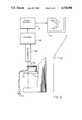
- FIG. 8is a schematic view of an apparatus which is used to locate the centroid of the core of an optical fiber which is terminated by a plug and a connector body;
- FIG. 9is a plan view of a portion of the apparatus of FIG. 8.
- FIGS. 10-14are a sequence of views to illustrate steps of the inventive method for causing alignment of optical fiber cores in plugs with distances from longitudinal axes of the plugs to centroids of the cores being exaggerated for purposes of clarity;
- FIGS. 15A-15C and 16A-16Cshow the alignment of fiber cores in passageways in accordance with this invention with distances from longitudinal axes of plugs to centroids of the cores being exaggerated for purposes of clarity;
- FIGS. 17A-17Cillustrate an alternative embodiment of the invention with distances from longitudinal axes of plugs to centroids of the optical fiber cores being exaggerated for purposes of clarity.
- each of the optical fiber cables 22 and 24includes a single optical fiber 26 (see FIG. 1A) having a core 25 and a cladding 27 enclosed in a coating 28 and having a tube 31 of polyvinyl chloride (PVC) extruded thereabout (see FIG. 1B).
- PVCpolyvinyl chloride
- Covering the tube 31 of PVCis a strength member 33 such as one made of Kevlar® fibrous material, for example, and an outer jacket 35 which may be comprised of PVC.
- the connector 20comprises two optical fiber terminations, each designated generally by the numeral 37. Corresponding elements of the terminations 37--37 are identified with the same numerals.
- the connector 20is such that longitudinal axes 38--38 of the terminations are coaxial.
- each termination 37comprises an optical fiber terminus or plug 40, having a passageway 41 (see FIG. 4) and being made of a ceramic material.
- the plug 40has an outer diameter of about 2500 microns.
- An end face 39 of the plug 40includes an opening of the passageway 41.
- the coating 28, as well as the tube 31, strength member 33 and outer jacket 35,is removed from an end portion of an optical fiber 26 prior to its termination with a plug 40. Then the end portion of the optical fiber 26 is inserted into the passageway 41 of each plug 40 such that the end face of the optical fiber extends slightly beyond the end face 39 of the plug.
- the bared optical fiberhas an outer diameter of 125 microns whereas the diameter of the passageway 41 is about 127 microns. Then the end portion of the optical fiber 26 is secured within the passageway 41 of the plug 40 and the end faces of the optical fiber and of the plug are ground and polished.
- Each terminationalso includes a connector body 42 made of a plastic or metallic material, a compression spring 44 and a tubular housing 45 made of a metallic material. It should be observed that the plug 40, the connector body 42 and the housing 45 each have a cylindrical cross-section.
- the connector body 42includes a separate orienting pin 43 which can be installed at any of an infinite number of positions in accordance with this invention and which projects radially from the longitudinal axis 38.
- the connector body 42includes a smaller diameter portion 46 (see FIG. 3) which extends through an opening 47 in an internally disposed collar 48 in the housing.
- a retaining washer 49circumscribes the smaller diameter portion on the outer side of the collar.
- the spring 44is disposed about the smaller diameter portion 46 of the connector body 42 between the collar and a large diameter portion 51. As a result of this arrangement, the spring 44 biases the connector body 42 outwardly from the cable to hold the connector body within the housing 45.
- the housing 45includes a longitudinally extending slot 55 which at its inner end communicates with a circumferentially extending slot 57.
- the slot 57is formed so that the tubular wall of the housing which defines it includes a latching projection 58.
- a portion 59which extends from the housing 45 along the optical fiber cable in a conically shaped configuration until it assumes the general cross-section of the cable.
- This portion of the connector 20provides strain relief for the termination and insures that the cable can withstand repeated bends in use after interconnection with another cable without undue stresses being imparted to the optical fibers.
- the coupler 60includes a tubular member 62 having end portions 64 and 66 with each end portion including a longitudinally extending slot 67.
- the coupler 60includes a center portion 68 which is threaded and which is adapted to be inserted in a hole (not shown) in a panel.
- a nut 71is turned thereonto to secure the coupler to the panel.
- assembly pins 73--73are displaced circumferentially from the slot 67 at that end.
- a sleeve 75(see also FIG. 4).
- the sleeve 75is adapted to receive the plugs 40--40 of the terminations 37--37 and is a means for aligning the outer surfaces of the plugs.
- the sleeve 75is disposed within the coupler 60 such that it floats to allow for some movement of the plugs 40--40 when they are inserted into the coupler. Further, the sleeve 75 causes the longitudinal axes 38--38 of the plugs 40--40 mounted therein to be coaxial.
- the installerin assembling the connector 20, inserts the plug 40 of one of the terminations 37--37 into the sleeve 75 with the pin 73 of the coupler being received in the longitudinally extending slot 55 of the termination.
- the installerhas caused the pin 43 which extends radially from the connector body 42 of the one termination 37 to be received in a longitudinal slot 67 of the coupler 60.
- the movement of the plug 40is discontinued when the pin 43 engages an inner end of the wall which defines the slot 67.
- Continued movement of the housing 45 against the bias of the spring 44causes the housing to override the connector body.
- the operatorturns the housing 45 to cause the pin 73 to become disposed and secured within the circumferentially extending slot 57 behind the latching portion 58 (see FIG. 3). It should be observed that the housing 45 is free to turn about the plug 40 and its associated connector body 42. This allows the housing 45 to be turned independently of the connector body 42 to cause the pin 73 to become disposed behind the latching portion 58.
- the installerrepeats the procedure with respect to the other termination 37 to cause the plug 40 thereof to be received within the floating sleeve 75. It should be observed that because of dual pins at each end of the coupler 60, either end may be inserted into a panel.
- the geometries of the coupler 60 and of the terminations 37--37are such that when the plugs 40--40 are received within the floating sleeve 75, and the pins 43--43 bottomed out in the slots 67--67 of the coupler 60, end faces of the plugs 40--40 abut each other (see FIGS. 3 and 4). As a result, transmission losses through the connector 20 are minimized.
- the connector bodies 42--42 and pins 43--43are shown in FIG. 5 to relate the orientation of the optical fibers thereto. It has been determined that the centroid of each passageway in a production plug might lie as much as perhaps 3 microns from the longitudinal axis of its associated plug. Although the passageways in FIG. 5 are disposed along a diametrical line 79, they are on diametrically opposite sides of a longitudinal axis of the plugs 40--40 and may have their centroids spaced apart as much as 6 microns when the plugs are assembled in a sleeve 75 (see FIG. 5C).
- the fiber cores 25--25may be disposed eccentrically with respect to the claddings by as much as 1 micron, there is a potential for another 2 microns of offset when two fibers are connected. Further, the passageways in the plugs have a clearance of one micron about the clad fibers. This also adds to the potential misalignment between the cores. The worst offset under these conditions may be as much as 10 microns.
- the optimal alignment of the optical fibers 26--26is accomplished by the methods and devices of this invention which rely on a predetermined orientation of the optical fiber cores 25--25 with respect to the pins 43--43 extending from the connector bodies 42--42. More specifically, the methods of this invention include the location and machine vision marking or other suitable marking of the radial orientation of the fiber cores 25--25 which extend through the plugs 40--40 with respect to a longitudinal axis of the connector and their alignment in a particular manner to insure that the optical fiber cores 25--25 are aligned (see FIG. 6) at least radially. Such a technique results in the cores being offset no more than 5 microns.
- FIG. 7An enlarged view of how the cores 25--25 and passageways 41--41 may overlap while being aligned in a radial direction is shown in FIG. 7.
- An apparatus 80(see FIG. 8) is used to assembly a pin 43 with a connector body 42 in accordance with this invention to cause the pin to be aligned with the centroid of the core 25 of an optical fiber 26 in a passageway 41.
- a base 81having a V-shaped support trough 82 formed therein. Extending across the trough 82 is an arm 84 having a bearing pad 85 made of TEFLON® plastic, for example, mounted thereon. The bearing pad is adapted to engage the outer surface of a plug 40 which is positioned in the trough 82 for core location.
- the base 81also includes a relief slot 86 which opens to the trough 82.
- the base 81is supported on a moveable stage 87 which is adapted to be moved in the vertical coordinate direction to cause the end face of the optical fiber 26 terminated by the plug 40 held in the trough 82 to be aligned with and in the focal plane of an objective 88 of a microscope 89 (see FIG. 8).
- An eyepiece of the microscopeis adapted to be viewed by a television camera 90 which is connected to a machine vision system 91.
- the machine vision systemprovides an input to a monitor screen 92.
- the machine vision system 91also is used to calculate the position of the centroid of the optical fiber core for a given orientation of the plug 40.
- a light source 94is positioned to illuminate the core 25 of the optical fiber held in the trough 82.
- each plug 40 having an end portion of an optical fiber 26 secured within its passageway 41 as described hereinbeforeis caused to be disposed within the V-shaped support trough 82 (see FIG. 9), for example, and appropriate facilities used in order to locate centroid 96a (see FIG. 10) of the core 25 in the end face 39 of the plug.
- the core 25is illuminated by the source 94 and the microscope is focused.
- An image 95a (see FIG. 8) of the core 25 which is seen in the monitor 92is processed by the machine vision system, and the centroid of the core is calculated electronically.
- the apparatus 80is used to record the location 96a adjacent to the end face of the plug 40 at an initial location.
- the displacement of the cores with respect to the longitudinal axes of the plugsis not. It will be recalled that the diameter of the plug is about 2500 microns, the diameter of the passageway is about 127 microns, the diameter of the clad fiber is 125 microns, and the diameter of the core is 8 to 50 microns. Also, the maximum distance by which the centroid of the core is offset from the longitudinal axis 38 in a production plug 40 is 5 microns. The displacement, which is more accurately depicted in FIG. 7, is exaggerated in FIGS. 10-17 in order to more clearly depict the alignment steps of this invention.
- the plug 40 within the support 82is caused to be turned through an angle of 180° (see FIG. 11) to locate the centroid of the core 25 in the rotated position of the core.
- the image of the core in its rotated position on the monitoris designated 95b (see FIG. 8).
- the centroid of the core 25is designated 96b.
- the location 96b adjacent to the end face of the plug 40 and after rotationis recorded. It should be understood that although the core locations in FIGS. 10-14 and in ensuing figures are depicted along a vertical axis, they may be at any radial position about an end face of the plug 40.
- a line 97see FIG.
- the intersection 99may take several forms. It may comprise an inked mark or it simply may be a reference point which provides an indication of an angle by which the radial line 98 is displaced from a reference coordinate axis of the end face of the plug 40.
- the intersection 99 adjacent to the periphery of the plug 40is made such that the core 25 always is positioned in a particular way relative to the intersection and the longitudinal axis 38 of the plug.
- the core 25is disposed either at the longitudinal axis 38 of the plug 40 or between the longitudinal axis 38 and the intersection 99 adjacent to the periphery thereof.
- the plug assemblyis moved into another fixture (not shown) and turned until its location 99 is caused to be aligned with a drill.
- a holeis provided in the connector body 42.
- the pin 43is assembled with and secured to the connector body 42 such that the intersection 99 on the periphery of the plug is aligned with the pin 43 on the connector body (see FIG. 14).
- itis the radially extending centerline of the pin 43 which is aligned with the intersection 99 and hence with the core centroid.
- the connector bodymay be provided with a depression or dimple in alignment with the centroid of the optical fiber core of the associated plug.
- the coupleris provided with an internally projecting lug which becomes disposed in the depression of the connector body when the plug 40 is inserted into the sleeve 75.
- Each termination 37includes a terminated optical fiber 26 received in a passageway 41 in which the centroid of the fiber core 25 is aligned intentionally with a pin 43 extending radially from the connector body 42 thereof. It should be noted that all terminations 37--37 are assembled in exactly the same way thereby rendering them interchangeable for mounting in the coupler 60.
- the plugs 40--40are inserted into the sleeve 75 such that the end faces 39--39, in which the centroids of the fiber cores have been determined, are adjacent to each other.
- each of the plugs 40--40terminates an optical fiber 26 the core 25 of which is aligned radially with the pin 43 of the connector body 42 in which the plug is received.
- the pin 43 of each termination 37is received in one of the slots 67--67 when the termination is assembled to the coupler 60.
- the optical fiber cores 25--25 of plugs 40--40 which are mounted in a coupler 60are always aligned in a plane which originates at the coaxial longitudinal axes 38--38 and which extends radially thereof through the slots 67--67 which themselves are aligned.
- centroids of coresare caused to be disposed in a common radial plane and on the same side of the longitudinal axes.
- Centroid 101 of a core 102 (see FIG. 15A) of one plug 40is caused to be aligned with a pin 43 and disposed between the pin and the longitudinal axis 38 of the plug.
- centroid 103 of a core 104 (see FIG. 15B) of another plugis caused to be aligned with a pin 43 and disposed between the pin and the longitudinal axis of that plug.
- the connector bodies 42--42are assembled to the sleeve within the coupler 60 in a way to cause the pins 43--43 to be aligned in a common radial plane which originates at and extends from the coaxial longitudinal axes 38--38.
- the fiber coresalthough offset from the longitudinal axes, are not only disposed in a common plane but are aligned substantially longitudinally (see FIG. 15C).
- the centroid of one core 106may be coincident with the longitudinal axis 38 of the plug 40, and another 107, disposed between the longitudinal axis 38 of its plug and the plug periphery. Otherwise, the centroids of the cores of both plugs are disposed between the longitudinal axes 38--38 and the peripheries of the plugs as shown in FIG. 15C.
- the preferred embodimenthas been described always to have the centroids of the plug cores coincident with the longitudinal axes 38--38 of the plugs 40--40 or disposed between the longitudinal axes and the pins 43--43 of the connector bodies 42--42, this is not necessary.
- the orienting processis carried out so that the longitudinal axes 38--38 of the plugs 40--40 become disposed between the associated pins 43--43 and centroids 111 and 112 of cores 113 and 114.
- all plugs 40--40are oriented in the same manner and assembled with a connector body in the same way.
Landscapes
- Physics & Mathematics (AREA)
- General Physics & Mathematics (AREA)
- Optics & Photonics (AREA)
- Chemical & Material Sciences (AREA)
- Organic Chemistry (AREA)
- Engineering & Computer Science (AREA)
- Chemical Kinetics & Catalysis (AREA)
- Electrochemistry (AREA)
- Materials Engineering (AREA)
- Metallurgy (AREA)
- Mechanical Coupling Of Light Guides (AREA)
Abstract
Description
Claims (21)
Priority Applications (8)
| Application Number | Priority Date | Filing Date | Title |
|---|---|---|---|
| US06/749,909US4738508A (en) | 1985-06-28 | 1985-06-28 | Terminated optical fiber and methods of making |
| CA000510323ACA1252662A (en) | 1985-06-28 | 1986-05-29 | Terminated optical fiber and methods of making |
| DE8686107357TDE3686672T2 (en) | 1985-06-28 | 1986-05-30 | END PIECE FOR OPTICAL FIBER AND METHOD FOR PRODUCING IT. |
| EP86107357AEP0205984B1 (en) | 1985-06-28 | 1986-05-30 | Terminated optical fiber and methods of making |
| JP61124755AJPS6211807A (en) | 1985-06-28 | 1986-05-31 | Terminated optical fiber and its manufacturing method |
| KR1019860004311AKR940002264B1 (en) | 1985-06-28 | 1986-05-31 | Terminated fiber and its manufacturing method |
| CN86104201ACN1019609B (en) | 1985-06-28 | 1986-06-19 | Terminated optical fiber and its method of termination |
| JP007885UJPH08627U (en) | 1985-06-28 | 1995-07-31 | Terminated optical fiber |
Applications Claiming Priority (1)
| Application Number | Priority Date | Filing Date | Title |
|---|---|---|---|
| US06/749,909US4738508A (en) | 1985-06-28 | 1985-06-28 | Terminated optical fiber and methods of making |
Publications (1)
| Publication Number | Publication Date |
|---|---|
| US4738508Atrue US4738508A (en) | 1988-04-19 |
Family
ID=25015723
Family Applications (1)
| Application Number | Title | Priority Date | Filing Date |
|---|---|---|---|
| US06/749,909Expired - LifetimeUS4738508A (en) | 1985-06-28 | 1985-06-28 | Terminated optical fiber and methods of making |
Country Status (7)
| Country | Link |
|---|---|
| US (1) | US4738508A (en) |
| EP (1) | EP0205984B1 (en) |
| JP (2) | JPS6211807A (en) |
| KR (1) | KR940002264B1 (en) |
| CN (1) | CN1019609B (en) |
| CA (1) | CA1252662A (en) |
| DE (1) | DE3686672T2 (en) |
Cited By (54)
| Publication number | Priority date | Publication date | Assignee | Title |
|---|---|---|---|---|
| US4792205A (en)* | 1986-05-15 | 1988-12-20 | Radiall Industrie | Ferrule of a connector for single-mode optical fibers with polarization maintenance and the process for its adjustment |
| US4815809A (en)* | 1987-07-31 | 1989-03-28 | Robert M. Rodrick | Method and apparatus for terminating an optical fiber |
| US4867523A (en)* | 1988-10-28 | 1989-09-19 | American Telephone And Telegraph Company, At&T Bell Laboratories | Optical fiber connector including serpentine grooved member actuated by longitudinal forces |
| US4880291A (en)* | 1988-02-04 | 1989-11-14 | American Telephone & Telegraph Company, At&T Bell Laboratories | Optical fiber connector and methods of making |
| US4898446A (en)* | 1988-10-28 | 1990-02-06 | American Telephone And Telegraph Company, At&T Bell Laboratories | Optical fiber connector |
| US4953941A (en)* | 1988-11-21 | 1990-09-04 | Seikoh Giken Co., Ltd. | Optical fiber connecting device |
| US4979791A (en)* | 1989-12-08 | 1990-12-25 | Amp Incorporated | Laser diode connector assembly |
| US5101807A (en)* | 1989-02-10 | 1992-04-07 | Olympus Optical Co., Ltd. | Endoscope connecting apparatus |
| US5170452A (en)* | 1991-09-09 | 1992-12-08 | Porta Systems Corp. | Fiber optic plug connector and adapter therefor |
| US5212752A (en)* | 1992-05-27 | 1993-05-18 | At&T Bell Laboratories | Optical fiber ferrule connector having enhanced provisions for tuning |
| US5337392A (en)* | 1992-07-29 | 1994-08-09 | Alcatel Cit | Method of coupling an optical fiber to an optical component on the same substrate |
| US5337377A (en)* | 1992-12-15 | 1994-08-09 | Seikoh Giken Co., Ltd. | Optical fiber termination device |
| US5390269A (en)* | 1992-12-23 | 1995-02-14 | Methode Electronics, Inc. | Fiber optic connector with high resolution tunable fiber holder |
| US5482451A (en)* | 1992-12-03 | 1996-01-09 | E. I. Du Pont De Nemours | Apparatus for the preparation of optical ferrules |
| US5535002A (en)* | 1995-04-27 | 1996-07-09 | At&T Corp. | Band matching system and method for enabling accurate determination of a disparity between two surfaces using an interferometer |
| US5543915A (en)* | 1995-04-27 | 1996-08-06 | At&T Corp. | Autofocusing system and method for positioning an interferometric fringe over a target in an image |
| US5587116A (en)* | 1992-12-03 | 1996-12-24 | E. I. Du Pont De Nemours And Company | Process for injection molding optical ferrules |
| US5600439A (en)* | 1995-04-27 | 1997-02-04 | Lucent Technologies Inc. | Self-calibration system and method for determining the adequacy of an interferometer angle and surface curvatures in an inspection system for determining disparity between two surfaces |
| EP0757228A2 (en) | 1995-08-02 | 1997-02-05 | AT&T IPM Corp. | Automatic inspection system for contactlessly measuring an offset of a central feature of an object |
| EP0757227A2 (en) | 1995-08-02 | 1997-02-05 | AT&T IPM Corp. | Alignment and lighting system and method for aligning and lighting an object for an inspection system that contactlessly measures an offset of a central feature of the object |
| EP0758742A2 (en) | 1995-08-02 | 1997-02-19 | AT&T IPM Corp. | Balanced focus system and method for achieving optimal focus of different areas of an object that are concurrently imaged |
| US5636020A (en)* | 1995-04-27 | 1997-06-03 | Lucent Technologies Inc. | Zone analysis system and method for optimizing the performance of an inspection system for determining disparity between two surfaces |
| US5671049A (en)* | 1995-04-27 | 1997-09-23 | Lucent Technologies Inc. | System and method for contactlessly and automatically determining the return loss of an optical fiber connector |
| US5809162A (en)* | 1995-12-22 | 1998-09-15 | Lucent Technologies Inc. | Surface analysis system and method |
| US5898494A (en)* | 1995-04-27 | 1999-04-27 | Lucent Technologies Inc. | Automatic inspection system and method for contactlessly measuring the disparity between two surfaces |
| US5923781A (en)* | 1995-12-22 | 1999-07-13 | Lucent Technologies Inc. | Segment detection system and method |
| US5924234A (en)* | 1997-11-20 | 1999-07-20 | Trijicon, Inc. | Optical sighting device |
| EP0938003A1 (en)* | 1998-02-24 | 1999-08-25 | Jds Fitel Inc. | Tunable multiple fiber optical connector |
| US5984533A (en)* | 1998-02-26 | 1999-11-16 | Meteor Optics, Inc. | Optical fiber connector |
| US6011616A (en)* | 1998-10-02 | 2000-01-04 | Lucent Technologies, Inc. | Systems and methods for measuring the concentricity of a core to a ferrule |
| US6188825B1 (en) | 1999-04-15 | 2001-02-13 | Lucent Technologies, Inc. | Dust cover for protecting optical fiber sleeve housing |
| US6283640B1 (en) | 1999-04-01 | 2001-09-04 | Lucent Technologies Inc. | Tunable optical fiber buildout |
| US6367984B1 (en) | 1999-11-10 | 2002-04-09 | Lucent Technologies, Inc. | Optical fiber adapter |
| US6398423B1 (en) | 1999-12-15 | 2002-06-04 | Itt Manufacturing Enterprises, Inc. | Optic fiber retaining system |
| US6447172B1 (en) | 1999-04-01 | 2002-09-10 | Fitel Usa Corp. | Sleeve holder for optical fiber buildout |
| US6524014B2 (en) | 1999-04-01 | 2003-02-25 | Fitel Usa Corp. | Universal modular optical fiber buildout |
| US20030138217A1 (en)* | 2002-01-24 | 2003-07-24 | Lecomte Fabrice | Easy-to-mount optical connector system |
| WO2003062892A1 (en)* | 2002-01-24 | 2003-07-31 | Hubert + Suhner Ag | Sleeve receiving element for the coupling of an optical plug-type connector |
| US20040047586A1 (en)* | 2002-09-06 | 2004-03-11 | Trijicon, Inc. | Reflex sight with multiple power sources for reticle |
| EP1251374A3 (en)* | 2001-04-17 | 2004-03-24 | Itt Manufacturing Enterprises, Inc. | Terminus retainer |
| US6723951B1 (en) | 2003-06-04 | 2004-04-20 | Siemens Westinghouse Power Corporation | Method for reestablishing holes in a component |
| US6742936B1 (en)* | 2000-11-06 | 2004-06-01 | Corning Cable Systems Llc | Low-loss intermatable ferrules for optical fibers and a method of fabrication thereof |
| US20050226586A1 (en)* | 2002-07-16 | 2005-10-13 | Jan Watte | Device for cleaving an optical fibre |
| US20060093261A1 (en)* | 2004-10-27 | 2006-05-04 | Martin Weigert | Method and apparatus for optically coupling an optical waveguide to an optical module |
| US20060276690A1 (en)* | 2005-05-11 | 2006-12-07 | Farris Jesse L Iii | Visualization system |
| US8070366B1 (en)* | 2009-05-18 | 2011-12-06 | Lockheed Martin Corporation | Optical fiber connector and method |
| US20160139345A1 (en)* | 2013-01-23 | 2016-05-19 | Commscope, Inc. Of North Carolina | Cylindrical Optical Ferrule Alignment Apparatus |
| CN105750928A (en)* | 2016-04-01 | 2016-07-13 | 哈尔滨工程大学 | Mechanical structure for enabling optical fibers to axially rotate |
| US10025041B2 (en) | 2014-07-01 | 2018-07-17 | ADC Telecommunications (Shanghai) Distribution Co. Ltd. | Ferrule assembly and ferrule device |
| US10191226B2 (en) | 2013-01-23 | 2019-01-29 | Commscope, Inc. Of North Carolina | Cylindrical optical ferrule alignment apparatus |
| US10768378B2 (en) | 2014-07-01 | 2020-09-08 | Commscope Telecommunications (Shanghai) Co. Ltd. | Fiber alignment device, ferrule device and method of manufacturing the ferrule device |
| US11150412B2 (en) | 2018-01-31 | 2021-10-19 | Commscope Technologies Llc | Tunable fiber optic connectors |
| US20220069484A1 (en)* | 2020-08-27 | 2022-03-03 | Tyco Electronics (Shanghai) Co. Ltd. | Connector Visual Inspection Apparatus |
| US11307363B2 (en) | 2016-10-11 | 2022-04-19 | Commscope Technologies Llc | Ferrule assembly, method for manufacturing a ferrule assembly and optical fiber fixing mold |
Families Citing this family (10)
| Publication number | Priority date | Publication date | Assignee | Title |
|---|---|---|---|---|
| EP0280562A2 (en)* | 1987-02-26 | 1988-08-31 | BICC Public Limited Company | Optical fibre splicing |
| EP0330231B1 (en)* | 1988-02-26 | 1995-05-10 | Nippon Telegraph And Telephone Corporation | Plug-in connector |
| US5028114A (en)* | 1988-09-29 | 1991-07-02 | Siemens Aktiengesellschaft | Plug connector for fiber optic cables |
| JPH08643Y2 (en)* | 1989-02-03 | 1996-01-10 | 沖電気工業株式会社 | Optical connector element |
| JP2624339B2 (en)* | 1989-08-28 | 1997-06-25 | 日本電気株式会社 | Bayonet lock optical connector |
| DE4120038A1 (en)* | 1991-06-18 | 1992-12-24 | Broadcast Television Syst | CONNECTOR FOR LIGHTWAVE GUIDE |
| KR950004882B1 (en)* | 1992-12-29 | 1995-05-15 | 재단법인 한국전자통신연구소 | Rotating and alignment device of assembly system for low connection loss of optical connector for optical fiber connection |
| EP1041413A1 (en)* | 1999-04-01 | 2000-10-04 | Lucent Technologies Inc. | Universal snap-fit buildout base and mounting panel system |
| CN103412377B (en)* | 2013-08-28 | 2015-07-15 | 南京华脉科技股份有限公司 | An optical fiber splice protector |
| CN105445861A (en)* | 2014-07-01 | 2016-03-30 | 泰科电子(上海)有限公司 | Plug core device and plug core device manufacturing apparatus and method |
Citations (14)
| Publication number | Priority date | Publication date | Assignee | Title |
|---|---|---|---|---|
| US3938895A (en)* | 1974-08-19 | 1976-02-17 | Gte Laboratories Incorporated | Method for positioning an optical fiber |
| US4057322A (en)* | 1975-11-05 | 1977-11-08 | International Telephone And Telegraph Corporation | Precision surface optical fibers |
| US4113346A (en)* | 1975-11-20 | 1978-09-12 | International Standard Electric Corporation | Method of making optical fiber terminations |
| US4193664A (en)* | 1977-03-11 | 1980-03-18 | International Standard Electric Corporation | Optical fiber connector |
| US4203650A (en)* | 1977-05-31 | 1980-05-20 | Les Cables De Lyon | Connector for simultaneous end-to-end connection of groups of seven optical fibres |
| US4215937A (en)* | 1979-01-29 | 1980-08-05 | International Telephone And Telegraph Corporation | Method and apparatus for detecting optimum alignment of optical fibers in a connector arrangement |
| US4240695A (en)* | 1979-06-20 | 1980-12-23 | E. I. Du Pont De Nemours And Company | Optical fibers connector |
| US4265511A (en)* | 1978-06-26 | 1981-05-05 | U.S. Philips Corporation | Detachable connector for optical fibres |
| US4289374A (en)* | 1978-09-26 | 1981-09-15 | U.S. Philips Corporation | Method of and device for providing a concentric envelope on an end of an optical fiber, and fiber having an end provided with a concentric envelope in accordance with the method |
| US4300815A (en)* | 1978-10-27 | 1981-11-17 | Socapex | Connector end fitting for optical monofibre |
| US4353620A (en)* | 1980-05-14 | 1982-10-12 | Trw Inc. | Optical fiber connector construction |
| US4458985A (en)* | 1981-10-16 | 1984-07-10 | International Business Machines Corporation | Optical fiber connector |
| US4506947A (en)* | 1981-11-18 | 1985-03-26 | Kokusai Denshin Denwa Kabushiki Kaisha | Method and apparatus for core alignment of optical fibers |
| US4545644A (en)* | 1983-10-04 | 1985-10-08 | At&T Bell Laboratories | Optical fiber connector and articles connected therewith |
Family Cites Families (10)
| Publication number | Priority date | Publication date | Assignee | Title |
|---|---|---|---|---|
| JPS50136045A (en)* | 1974-04-15 | 1975-10-28 | ||
| JPS5216239A (en)* | 1975-07-28 | 1977-02-07 | Tech Res & Dev Inst Of Japan Def Agency | Connector for photo fiber cable |
| DE2640973C2 (en)* | 1976-09-11 | 1981-08-20 | Standard Elektrik Lorenz Ag, 7000 Stuttgart | Connection device for light guides |
| US4146288A (en)* | 1977-11-11 | 1979-03-27 | International Standard Electric Corporation | Bayonet connector coupling arrangement |
| CA1093873A (en)* | 1978-06-05 | 1981-01-20 | Helmut H. Lukas | Optical fibre connector |
| JPS5857811B2 (en)* | 1978-11-10 | 1983-12-22 | 松下電器産業株式会社 | Rotating head assembly for magnetic recording and reproducing equipment |
| JPS58152212A (en)* | 1982-03-05 | 1983-09-09 | Nec Corp | Optical connector |
| JPS59111119A (en)* | 1982-12-15 | 1984-06-27 | Hirose Denki Kk | Bayonet locking type optical fiber connector |
| JPS59140411A (en)* | 1983-02-01 | 1984-08-11 | Seiko Instr & Electronics Ltd | Optical fiber connector |
| JPS60196706A (en)* | 1984-03-21 | 1985-10-05 | Nippon Telegr & Teleph Corp <Ntt> | Connecting method of optical fiber |
- 1985
- 1985-06-28USUS06/749,909patent/US4738508A/ennot_activeExpired - Lifetime
- 1986
- 1986-05-29CACA000510323Apatent/CA1252662A/ennot_activeExpired
- 1986-05-30EPEP86107357Apatent/EP0205984B1/ennot_activeExpired - Lifetime
- 1986-05-30DEDE8686107357Tpatent/DE3686672T2/ennot_activeExpired - Fee Related
- 1986-05-31JPJP61124755Apatent/JPS6211807A/enactivePending
- 1986-05-31KRKR1019860004311Apatent/KR940002264B1/ennot_activeExpired - Fee Related
- 1986-06-19CNCN86104201Apatent/CN1019609B/ennot_activeExpired
- 1995
- 1995-07-31JPJP007885Upatent/JPH08627U/enactivePending
Patent Citations (14)
| Publication number | Priority date | Publication date | Assignee | Title |
|---|---|---|---|---|
| US3938895A (en)* | 1974-08-19 | 1976-02-17 | Gte Laboratories Incorporated | Method for positioning an optical fiber |
| US4057322A (en)* | 1975-11-05 | 1977-11-08 | International Telephone And Telegraph Corporation | Precision surface optical fibers |
| US4113346A (en)* | 1975-11-20 | 1978-09-12 | International Standard Electric Corporation | Method of making optical fiber terminations |
| US4193664A (en)* | 1977-03-11 | 1980-03-18 | International Standard Electric Corporation | Optical fiber connector |
| US4203650A (en)* | 1977-05-31 | 1980-05-20 | Les Cables De Lyon | Connector for simultaneous end-to-end connection of groups of seven optical fibres |
| US4265511A (en)* | 1978-06-26 | 1981-05-05 | U.S. Philips Corporation | Detachable connector for optical fibres |
| US4289374A (en)* | 1978-09-26 | 1981-09-15 | U.S. Philips Corporation | Method of and device for providing a concentric envelope on an end of an optical fiber, and fiber having an end provided with a concentric envelope in accordance with the method |
| US4300815A (en)* | 1978-10-27 | 1981-11-17 | Socapex | Connector end fitting for optical monofibre |
| US4215937A (en)* | 1979-01-29 | 1980-08-05 | International Telephone And Telegraph Corporation | Method and apparatus for detecting optimum alignment of optical fibers in a connector arrangement |
| US4240695A (en)* | 1979-06-20 | 1980-12-23 | E. I. Du Pont De Nemours And Company | Optical fibers connector |
| US4353620A (en)* | 1980-05-14 | 1982-10-12 | Trw Inc. | Optical fiber connector construction |
| US4458985A (en)* | 1981-10-16 | 1984-07-10 | International Business Machines Corporation | Optical fiber connector |
| US4506947A (en)* | 1981-11-18 | 1985-03-26 | Kokusai Denshin Denwa Kabushiki Kaisha | Method and apparatus for core alignment of optical fibers |
| US4545644A (en)* | 1983-10-04 | 1985-10-08 | At&T Bell Laboratories | Optical fiber connector and articles connected therewith |
Non-Patent Citations (2)
| Title |
|---|
| Publications: Y. Kawamura et al. "Optical Connectors for Singlemode Fiber Lasers and Applications, Sep. 1984, beginning at p. 57. |
| Publications: Y. Kawamura et al. Optical Connectors for Singlemode Fibers , Lasers and Applications, Sep. 1984, beginning at p. 57.* |
Cited By (70)
| Publication number | Priority date | Publication date | Assignee | Title |
|---|---|---|---|---|
| US4792205A (en)* | 1986-05-15 | 1988-12-20 | Radiall Industrie | Ferrule of a connector for single-mode optical fibers with polarization maintenance and the process for its adjustment |
| US4815809A (en)* | 1987-07-31 | 1989-03-28 | Robert M. Rodrick | Method and apparatus for terminating an optical fiber |
| US4880291A (en)* | 1988-02-04 | 1989-11-14 | American Telephone & Telegraph Company, At&T Bell Laboratories | Optical fiber connector and methods of making |
| US4867523A (en)* | 1988-10-28 | 1989-09-19 | American Telephone And Telegraph Company, At&T Bell Laboratories | Optical fiber connector including serpentine grooved member actuated by longitudinal forces |
| US4898446A (en)* | 1988-10-28 | 1990-02-06 | American Telephone And Telegraph Company, At&T Bell Laboratories | Optical fiber connector |
| EP0366345A3 (en)* | 1988-10-28 | 1991-08-14 | AT&T Corp. | Optical connector |
| US4953941A (en)* | 1988-11-21 | 1990-09-04 | Seikoh Giken Co., Ltd. | Optical fiber connecting device |
| US5101807A (en)* | 1989-02-10 | 1992-04-07 | Olympus Optical Co., Ltd. | Endoscope connecting apparatus |
| US4979791A (en)* | 1989-12-08 | 1990-12-25 | Amp Incorporated | Laser diode connector assembly |
| US5170452A (en)* | 1991-09-09 | 1992-12-08 | Porta Systems Corp. | Fiber optic plug connector and adapter therefor |
| US5212752A (en)* | 1992-05-27 | 1993-05-18 | At&T Bell Laboratories | Optical fiber ferrule connector having enhanced provisions for tuning |
| USRE37079E1 (en) | 1992-05-27 | 2001-03-06 | Lucent Technologies Inc. | Optical fiber ferrule connector having enhanced provisions for tuning |
| USRE37080E1 (en) | 1992-05-27 | 2001-03-06 | Lucent Technologies Inc. | Optical fiber ferrule connector having enhanced provisions for tuning |
| US5337392A (en)* | 1992-07-29 | 1994-08-09 | Alcatel Cit | Method of coupling an optical fiber to an optical component on the same substrate |
| US5587116A (en)* | 1992-12-03 | 1996-12-24 | E. I. Du Pont De Nemours And Company | Process for injection molding optical ferrules |
| US5568581A (en)* | 1992-12-03 | 1996-10-22 | E. I. Du Pont De Nemours And Company | Injection molded optical ferrules and apparatus and processes for the preparation thereof |
| US5482451A (en)* | 1992-12-03 | 1996-01-09 | E. I. Du Pont De Nemours | Apparatus for the preparation of optical ferrules |
| US5337377A (en)* | 1992-12-15 | 1994-08-09 | Seikoh Giken Co., Ltd. | Optical fiber termination device |
| US5390269A (en)* | 1992-12-23 | 1995-02-14 | Methode Electronics, Inc. | Fiber optic connector with high resolution tunable fiber holder |
| US5535002A (en)* | 1995-04-27 | 1996-07-09 | At&T Corp. | Band matching system and method for enabling accurate determination of a disparity between two surfaces using an interferometer |
| US5543915A (en)* | 1995-04-27 | 1996-08-06 | At&T Corp. | Autofocusing system and method for positioning an interferometric fringe over a target in an image |
| US5600439A (en)* | 1995-04-27 | 1997-02-04 | Lucent Technologies Inc. | Self-calibration system and method for determining the adequacy of an interferometer angle and surface curvatures in an inspection system for determining disparity between two surfaces |
| US5898494A (en)* | 1995-04-27 | 1999-04-27 | Lucent Technologies Inc. | Automatic inspection system and method for contactlessly measuring the disparity between two surfaces |
| US5636020A (en)* | 1995-04-27 | 1997-06-03 | Lucent Technologies Inc. | Zone analysis system and method for optimizing the performance of an inspection system for determining disparity between two surfaces |
| US5671049A (en)* | 1995-04-27 | 1997-09-23 | Lucent Technologies Inc. | System and method for contactlessly and automatically determining the return loss of an optical fiber connector |
| US5768401A (en)* | 1995-08-02 | 1998-06-16 | Lucent Technologies Inc. | Balanced focus system and method for achieving optimal focus of different areas of an object that are concurrently imaged |
| US5862250A (en)* | 1995-08-02 | 1999-01-19 | Lucent Technologies Inc. | System and method for contactlessly and automatically determining the insertion loss of an optical fiber connector |
| EP0758742A2 (en) | 1995-08-02 | 1997-02-19 | AT&T IPM Corp. | Balanced focus system and method for achieving optimal focus of different areas of an object that are concurrently imaged |
| EP0757227A2 (en) | 1995-08-02 | 1997-02-05 | AT&T IPM Corp. | Alignment and lighting system and method for aligning and lighting an object for an inspection system that contactlessly measures an offset of a central feature of the object |
| EP0757226A3 (en)* | 1995-08-02 | 2000-02-02 | AT&T IPM Corp. | Automatic inspection method for contactlessly measuring an offset of a central feature of an object |
| EP0757228A2 (en) | 1995-08-02 | 1997-02-05 | AT&T IPM Corp. | Automatic inspection system for contactlessly measuring an offset of a central feature of an object |
| US5809162A (en)* | 1995-12-22 | 1998-09-15 | Lucent Technologies Inc. | Surface analysis system and method |
| US5923781A (en)* | 1995-12-22 | 1999-07-13 | Lucent Technologies Inc. | Segment detection system and method |
| US5924234A (en)* | 1997-11-20 | 1999-07-20 | Trijicon, Inc. | Optical sighting device |
| EP0938003A1 (en)* | 1998-02-24 | 1999-08-25 | Jds Fitel Inc. | Tunable multiple fiber optical connector |
| US5984533A (en)* | 1998-02-26 | 1999-11-16 | Meteor Optics, Inc. | Optical fiber connector |
| US6011616A (en)* | 1998-10-02 | 2000-01-04 | Lucent Technologies, Inc. | Systems and methods for measuring the concentricity of a core to a ferrule |
| US6283640B1 (en) | 1999-04-01 | 2001-09-04 | Lucent Technologies Inc. | Tunable optical fiber buildout |
| US6447172B1 (en) | 1999-04-01 | 2002-09-10 | Fitel Usa Corp. | Sleeve holder for optical fiber buildout |
| US6524014B2 (en) | 1999-04-01 | 2003-02-25 | Fitel Usa Corp. | Universal modular optical fiber buildout |
| US6188825B1 (en) | 1999-04-15 | 2001-02-13 | Lucent Technologies, Inc. | Dust cover for protecting optical fiber sleeve housing |
| US6367984B1 (en) | 1999-11-10 | 2002-04-09 | Lucent Technologies, Inc. | Optical fiber adapter |
| US6398423B1 (en) | 1999-12-15 | 2002-06-04 | Itt Manufacturing Enterprises, Inc. | Optic fiber retaining system |
| US6742936B1 (en)* | 2000-11-06 | 2004-06-01 | Corning Cable Systems Llc | Low-loss intermatable ferrules for optical fibers and a method of fabrication thereof |
| EP1251374A3 (en)* | 2001-04-17 | 2004-03-24 | Itt Manufacturing Enterprises, Inc. | Terminus retainer |
| WO2003062892A1 (en)* | 2002-01-24 | 2003-07-31 | Hubert + Suhner Ag | Sleeve receiving element for the coupling of an optical plug-type connector |
| US6705766B2 (en) | 2002-01-24 | 2004-03-16 | Fci | Easy-to-mount optical connector system |
| US20050074211A1 (en)* | 2002-01-24 | 2005-04-07 | Daniel Greub | Sleeve receiving element for the coupling of an optical plug-type connector |
| US20030138217A1 (en)* | 2002-01-24 | 2003-07-24 | Lecomte Fabrice | Easy-to-mount optical connector system |
| US7116882B2 (en) | 2002-07-16 | 2006-10-03 | Tyco Electronics Raychem Nv | Device for cleaving an optical fibre |
| US20050226586A1 (en)* | 2002-07-16 | 2005-10-13 | Jan Watte | Device for cleaving an optical fibre |
| US20040047586A1 (en)* | 2002-09-06 | 2004-03-11 | Trijicon, Inc. | Reflex sight with multiple power sources for reticle |
| US6807742B2 (en) | 2002-09-06 | 2004-10-26 | Trijicon, Inc. | Reflex sight with multiple power sources for reticle |
| US6723951B1 (en) | 2003-06-04 | 2004-04-20 | Siemens Westinghouse Power Corporation | Method for reestablishing holes in a component |
| US20060093261A1 (en)* | 2004-10-27 | 2006-05-04 | Martin Weigert | Method and apparatus for optically coupling an optical waveguide to an optical module |
| US7246951B2 (en)* | 2004-10-27 | 2007-07-24 | Infineon Technologies Fiber Optics Gmbh | Method and apparatus for optically coupling an optical waveguide to an optical module |
| US20060276690A1 (en)* | 2005-05-11 | 2006-12-07 | Farris Jesse L Iii | Visualization system |
| US8070366B1 (en)* | 2009-05-18 | 2011-12-06 | Lockheed Martin Corporation | Optical fiber connector and method |
| US9835808B2 (en)* | 2013-01-23 | 2017-12-05 | Commscope, Inc. Of North Carolina | Cylindrical optical ferrule alignment apparatus |
| US20160139345A1 (en)* | 2013-01-23 | 2016-05-19 | Commscope, Inc. Of North Carolina | Cylindrical Optical Ferrule Alignment Apparatus |
| US10191226B2 (en) | 2013-01-23 | 2019-01-29 | Commscope, Inc. Of North Carolina | Cylindrical optical ferrule alignment apparatus |
| US10754104B2 (en) | 2013-01-23 | 2020-08-25 | Commscope, Inc. Of North Carolina | Cylindrical optical ferrule alignment apparatus |
| US10025041B2 (en) | 2014-07-01 | 2018-07-17 | ADC Telecommunications (Shanghai) Distribution Co. Ltd. | Ferrule assembly and ferrule device |
| US10768378B2 (en) | 2014-07-01 | 2020-09-08 | Commscope Telecommunications (Shanghai) Co. Ltd. | Fiber alignment device, ferrule device and method of manufacturing the ferrule device |
| CN105750928A (en)* | 2016-04-01 | 2016-07-13 | 哈尔滨工程大学 | Mechanical structure for enabling optical fibers to axially rotate |
| CN105750928B (en)* | 2016-04-01 | 2017-11-21 | 哈尔滨工程大学 | A kind of mechanical structure realized optical fiber and rotated along axle center |
| US11307363B2 (en) | 2016-10-11 | 2022-04-19 | Commscope Technologies Llc | Ferrule assembly, method for manufacturing a ferrule assembly and optical fiber fixing mold |
| US11150412B2 (en) | 2018-01-31 | 2021-10-19 | Commscope Technologies Llc | Tunable fiber optic connectors |
| US20220069484A1 (en)* | 2020-08-27 | 2022-03-03 | Tyco Electronics (Shanghai) Co. Ltd. | Connector Visual Inspection Apparatus |
| US11761882B2 (en)* | 2020-08-27 | 2023-09-19 | Tyco Electronics (Shanghai) Co., Ltd. | Connector visual inspection apparatus |
Also Published As
| Publication number | Publication date |
|---|---|
| EP0205984B1 (en) | 1992-09-09 |
| KR940002264B1 (en) | 1994-03-19 |
| KR870000604A (en) | 1987-02-19 |
| CN86104201A (en) | 1987-04-01 |
| DE3686672T2 (en) | 1993-03-25 |
| JPS6211807A (en) | 1987-01-20 |
| CN1019609B (en) | 1992-12-23 |
| CA1252662A (en) | 1989-04-18 |
| DE3686672D1 (en) | 1992-10-15 |
| JPH08627U (en) | 1996-04-12 |
| EP0205984A1 (en) | 1986-12-30 |
Similar Documents
| Publication | Publication Date | Title |
|---|---|---|
| US4738508A (en) | Terminated optical fiber and methods of making | |
| US4738507A (en) | Optical fiber connectors and methods of making | |
| KR0133559B1 (en) | Optical fiber connector and method thereof | |
| US4699458A (en) | Fiber optic connector | |
| EP0244791B1 (en) | Optical fiber connector | |
| US4258977A (en) | Optical fibre connector | |
| US4325607A (en) | Apparatus for connecting optical fibers | |
| US5946436A (en) | Structure of optical connector and aligning method | |
| US6742936B1 (en) | Low-loss intermatable ferrules for optical fibers and a method of fabrication thereof | |
| US9052470B2 (en) | Expanded beam optical fibre connector | |
| RU2133050C1 (en) | Process of polishing of fibre-optical lugs | |
| US4605281A (en) | Self-aligning fiber optic connector | |
| US4919509A (en) | Mechanical connection for polarization-maintaining optical fiber and methods of making | |
| US5727101A (en) | Monolithic ferrule for receiving and positioning multiple optical fibers and an optical fiber connector incorporating same | |
| US20010026662A1 (en) | Tuned multiple fiber optic connector | |
| US10838153B2 (en) | Independently-floated compact duplex ferrule | |
| US20040062488A1 (en) | Fiber optic adapter sleeve | |
| US20060062524A1 (en) | Low-cost method and apparatus for establishing fiber optic connections | |
| JPH03145607A (en) | single fiber optical connector |
Legal Events
| Date | Code | Title | Description |
|---|---|---|---|
| AS | Assignment | Owner name:AT&T TECHNOLOGIES, INC, 1 OAK WAY, BERKELEY HEIGHT Free format text:ASSIGNMENT OF ASSIGNORS INTEREST.;ASSIGNOR:PALMQUIST, JOHN M.;REEL/FRAME:004439/0797 Effective date:19850627 | |
| STCF | Information on status: patent grant | Free format text:PATENTED CASE | |
| FEPP | Fee payment procedure | Free format text:PAYOR NUMBER ASSIGNED (ORIGINAL EVENT CODE: ASPN); ENTITY STATUS OF PATENT OWNER: LARGE ENTITY | |
| FPAY | Fee payment | Year of fee payment:4 | |
| FPAY | Fee payment | Year of fee payment:8 | |
| FEPP | Fee payment procedure | Free format text:PAYOR NUMBER ASSIGNED (ORIGINAL EVENT CODE: ASPN); ENTITY STATUS OF PATENT OWNER: LARGE ENTITY Free format text:PAYER NUMBER DE-ASSIGNED (ORIGINAL EVENT CODE: RMPN); ENTITY STATUS OF PATENT OWNER: LARGE ENTITY | |
| FPAY | Fee payment | Year of fee payment:12 | |
| AS | Assignment | Owner name:LUCENT TECHNOLOGIES INC., NEW JERSEY Free format text:ASSIGNMENT OF ASSIGNORS INTEREST;ASSIGNOR:AT&T CORP.;REEL/FRAME:012059/0893 Effective date:19960329 | |
| AS | Assignment | Owner name:FITEL USA CORPORATION, GEORGIA Free format text:ASSIGNMENT OF ASSIGNORS INTEREST;ASSIGNOR:LUCENT TECHNOLOGIES;REEL/FRAME:012946/0578 Effective date:20011116 |