US4738396A - Vehicle air conditioner - Google Patents
Vehicle air conditionerDownload PDFInfo
- Publication number
- US4738396A US4738396AUS07/058,039US5803987AUS4738396AUS 4738396 AUS4738396 AUS 4738396AUS 5803987 AUS5803987 AUS 5803987AUS 4738396 AUS4738396 AUS 4738396A
- Authority
- US
- United States
- Prior art keywords
- temperature
- blower
- speed
- setting means
- operational
- Prior art date
- Legal status (The legal status is an assumption and is not a legal conclusion. Google has not performed a legal analysis and makes no representation as to the accuracy of the status listed.)
- Expired - Fee Related
Links
- 230000004044responseEffects0.000claimsdescription5
- 239000002826coolantSubstances0.000claims2
- 239000000110cooling liquidSubstances0.000claims1
- 238000012886linear functionMethods0.000claims1
- 239000000498cooling waterSubstances0.000abstractdescription9
- 239000003570airSubstances0.000description15
- 238000010438heat treatmentMethods0.000description7
- XLYOFNOQVPJJNP-UHFFFAOYSA-NwaterSubstancesOXLYOFNOQVPJJNP-UHFFFAOYSA-N0.000description7
- 230000006870functionEffects0.000description4
- 238000001816coolingMethods0.000description3
- 238000010586diagramMethods0.000description3
- 230000001133accelerationEffects0.000description2
- 238000006243chemical reactionMethods0.000description2
- 238000000034methodMethods0.000description2
- 206010016326Feeling coldDiseases0.000description1
- 239000012080ambient airSubstances0.000description1
- 230000007423decreaseEffects0.000description1
- 238000002347injectionMethods0.000description1
- 239000007924injectionSubstances0.000description1
- 238000005057refrigerationMethods0.000description1
- 238000010257thawingMethods0.000description1
Images


Classifications
- B—PERFORMING OPERATIONS; TRANSPORTING
- B60—VEHICLES IN GENERAL
- B60H—ARRANGEMENTS OF HEATING, COOLING, VENTILATING OR OTHER AIR-TREATING DEVICES SPECIALLY ADAPTED FOR PASSENGER OR GOODS SPACES OF VEHICLES
- B60H1/00—Heating, cooling or ventilating [HVAC] devices
- B60H1/00642—Control systems or circuits; Control members or indication devices for heating, cooling or ventilating devices
- B60H1/00814—Control systems or circuits characterised by their output, for controlling particular components of the heating, cooling or ventilating installation
- B60H1/00821—Control systems or circuits characterised by their output, for controlling particular components of the heating, cooling or ventilating installation the components being ventilating, air admitting or air distributing devices
- B60H1/00828—Ventilators, e.g. speed control
- G—PHYSICS
- G05—CONTROLLING; REGULATING
- G05D—SYSTEMS FOR CONTROLLING OR REGULATING NON-ELECTRIC VARIABLES
- G05D23/00—Control of temperature
- G05D23/19—Control of temperature characterised by the use of electric means
- G05D23/1917—Control of temperature characterised by the use of electric means using digital means
- G—PHYSICS
- G05—CONTROLLING; REGULATING
- G05D—SYSTEMS FOR CONTROLLING OR REGULATING NON-ELECTRIC VARIABLES
- G05D23/00—Control of temperature
- G05D23/19—Control of temperature characterised by the use of electric means
- G05D23/20—Control of temperature characterised by the use of electric means with sensing elements having variation of electric or magnetic properties with change of temperature
Definitions
- the present inventionrelates to vehicle air conditioners, especially to a device for controlling the speed of revolution of the blower.
- a typical vehicle air conditionerconsists of a duct 1, a shutter 2 provided at the inlet of the duct, a blower 3, an evaporator 4, a mixing shutter 5, a heater core or radiator 6, a mode switching shutter 7, a defrosting outlet or vent 8, a face level outlet or vent 9, and a foot level outlet or vent 10.
- the evaporator 4consititutes a refrigeration circuit together with a compressor 11, a condensor 12, a receiver tank 13, and an expansion valve 14. The revolution of the engine (not shown) is transmitted to the compressor 11 through a magnetic clutch 16.
- An A/D converter 17is provided to convert respective analog signals of the compartment temperature Tr sensed by a compartment temperature sensor 18, the opening ⁇ of the mixing shutter 5 sensed by a position sensing potentiometer 19, the sunshine temperature Ts sensed by a sunshine sensor 20, the ambient temperature Ta sensed by an ambient air sensor 21, the evaporator temperature Tm sensed by an evaporator temperature sensor 22, and the desired temperature Td set by a temperature setting device 23 into the corresponding digital signals, which are fed to a controlling device 24.
- the controlling device 24is composed of, for example, a microcomputer and consists of a shutter controlling means 27 for controlling the shutter 2 through a switchng circuit 25 and an actuator 26, a compressor controlling means 29 for controlling the magnetic clutch 16 through a driving circuit 28, a blower controlling means 31 for controlling the blower 3 through a driving circuit 30, a mixing shutter controlling means 34 for controlling the mixing shutter 5 through an actuator 33, a mode switching shutter controlling means 37 for controlling the mode switching shutter 7 through a switching circuit 35 and an actuator 36, and an operational means 38 for computing the total signal T from the respective data Tr, Ts, Ta, Tm, and Td and feeding it to the respective controlling means.
- the signals from a manual switch 39 for controlling the blower and a water temperature switch 40 for sensing the water temperature of the radiatorare also fed to the controlling device 24.
- the compressor controlling means 29turns off the compressor 11 to keep the temperature of the evaporator 4 constant at the level.
- the blower controlling means 31consists of a start controlling section 31A which operates when the blower 3 starts upon start of the engine and an automatic controlling section 31B for controlling the blower 3 based on the total signal T in the automatic control mode.
- the start controlling section 31Aconsists of a start controlling section 31C operable at the start time of the heater and a start controlling section 31D operable at the starting time of the cooler.
- the automatic control section 31Bincludes a first setting section 31F responsive to the total signal T to read a driving voltage VS1 from a memory 31E and feed it to the blower 3. As shown in FIG. 6, the driving voltage VS1 takes a high or low status depending on the total signal T for driving the blower 3 in the automatic controlling mode.
- the start controlling section 31Chas a setting means 31H for reading a driving voltage VS2 from a memory 31G at the initial period of a heating operation to set the blower 3 at the number of revolutions corresponding to the voltage VS2.
- the start controlling section 31Dhas a setting section 31l for reading a driving voltage VS3 from a memory 31K at the initial period of a cooling operation to set the blower 3 at the number of revolutions corresponding to this voltage VS3.
- a switching means 31Nswitches the blower control from the first or second start controlling section 31C or 31D to the automatic controlling section 31B.
- the blower 3is controlled by the automatic control section 31B in the automatic control mode.
- the bloweris controlled by the driving voltage VS1 having a characteristic Z, as shown in FIG. 8, which is a function of the total signal T given by the following equation (2):
- the number of revolutions of the blower 3is automatically determined based on the respective temperature signals Td, Tr, Ta, Ts, and Tm.
- the blower 3is controlled by the automatic control section 31B in the automatic control mode after its speed of revolution reaches a predetermined starting level as the compartment temperature Tr is increased by the start control section 31C or 31D. If the automatic control mode is employed from the beginning, a strong blow of cold or hot air can be produced and the number of revolutions of the blower 3 is changed rapidly at the time of engine start, providing an uncomfortable air condition.
- the bloweris controlled by the driving voltage having a characteristic such as shown in FIG. 9, in which the operational temperature TP and the blower driving voltage V are taken as abscissa and ordinate, respectively.
- the computed temperature TPis given by
- Tdis the desired temperature set in the temperature setting device 23 and Tr is the compartment temperature sensed by the sensor 18 disposed in the vehicle compartment.
- the driving voltage characteristic l for starting the blower 3 in the heating operationbecomes a straight line joining points P1 and P2.
- the speed of revolution of the blower 3is increased from the point P1 corresponding to the operational temperature TP1 at which the engine cooling water reached a predetermined temperature (for example, 40° C.).
- the operational temperature TP1 at the point P1is referred to as the sensed operational temperature TP1.
- the blower 3rotates at a low speed with a low voltage applied when the power switch is turned on.
- the blower 3rotates at a high speed with a high voltage applied at the point P2 or operational temperature TP2 at which the operational temperature TP is, for example, 16° C.
- this operational temperatureis referred to as the desired conversion temperature TP2.
- the blower 3When the power switch 9 is turned on, the blower 3 starts to rotate at a low speed.
- the blower driving voltageincreases along the straight line l between the sensed operational temperature TP1 (P1) and the desired conversion temperature TP2 (P2) to increase the speed of the blower 3.
- the acceleration of the blowercan be controlled by adjusting the slope of the line l at the sensed operational temperature TP1 so as to enhance passenger's feeling. Then, the blower is operated in the automatic control mode.
- the blowercan be accelerated in response to an increase of the desired temperature Td or compartment temperature Tr so as to increase slowly the speed of a hot air flow, but there is a delay in operation of the water temperature switch because the water temperature switch is disposed in the vicinity of the heater core instead of sensing directly the water temperature. Consequently, the operational temperature TP becomes high when the compartment temperature is relatively high in the intermediate period or at the time of restarting.
- the point P1is shifted to a great extent toward the point P2, making a sharp slope la of the driving voltage.
- the bloweris accelerated too much to provide a comfortable heating condition. This shortcoming is felt especially in a vehicle with a direct injection diesel engine which produces little exhaust heat (or the ambient temperature is very low or the number of passengers is very large) because the temperature of the engine cooling water takes long time to reach 40° C. after the engine starts running.
- an improved control devicefor controlling the speed of the blower of a vehicle air conditioner in response to changes of an operational temperature TP which is a function of at least a compartment temperature Tr, wherein the improvement comprises first setting means for increasing the speed of said blower along a characteristic line, the slope of which varies with said operational temperature TP at a time when the temperature of engine cooling water reaches a first predetermined temperature; and second setting means for increasing the speed of said blower as a function of time when said operational temperature TP exceeds a second predetermined temperature Tl.
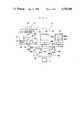
- FIG. 1is a block diagram of an air conditioner controlling device embodying the present invention.
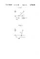
- FIGS. 2 and 3are graphs showing the characteristic of the controlling device of FIG. 1.
- FIG. 4is a flow chart for the controlling device of FIG. 1.
- FIG. 5is a block diagram of an air conditioner controlling device according to the prior art.
- FIG. 6is a block diagram of the blower controlling section of the controlling device of FIG. 5.
- FIGS. 7 through 9are graphs showing the characteristics of the controlling device of FIG. 5.
- the blower controlling device 41consists of a start controlling section 42 operable when the blower 3 starts to rotate and an automatic control section 43 for controlling the blower 3 in the automatic control mode.
- the automatic control section 43is the same as the automatic control section 31B of the prior art as shown in FIG. 6.
- the start control section 42consists of a first start control section 44 operable at the time of starting the heater and a second start control section 45 operable at the time of starting the cooler.
- the second or cooler start control section 45consists of a memory 45K and a setting means 45l. This second section 45 is the same as the start control section 31D and, therefore, its detailed description will be omitted.
- the first or heater start control section 44includes an operational means 44A responsive to the desired temperature Td set in the temperature setting means 23 and the compartment temperature Tr sensed by the sensor 18 disposed within the compartment to output the operational temperature TP given by the following equation
- a given temperature limit Tlfor example, 13° C. is set in an auxiliary temperature setting means 46.
- This temperature Tldetermines the limit point P3 at which the blower can be started to accelerate.
- the limit setting temperature Tlcan be any point close to the desired temperature TP2.
- the output TP of the operational means 44A and the output Tl of the auxiliary temperature setting means 46are compared in a comparator 47.
- the comparator 47When the operational temperature TP is higher than the set temperature Tl, the comparator 47 outputs a first sense signal ⁇ while TP is lower than Tl, it outputs a second sense signal ⁇ .
- a first setting means 48is responsive to the first sense signal ⁇ to read a voltage VS21 based on a predetermined characteristic 1c such as shown in FIG. 3 and feed it to the blower 3.
- the starting point of the characteristic 1cis set so as to agree with the point P3, and the terminating point with the point P2.
- the first driving voltage VS21increases with the time from the low status (P3) to the high status (P2) in a period of, for example, 90 seconds.
- a second setting means 50is responsive to the second sense signal ⁇ to output a voltage VS22 varying along the characteristic line l, as shown in FIG. 2, joining the point P1 corresponding to the operational temperature TP1, for example, 40° C. sensed by the water temperature switch 40 and the point P2 set by the setting means 52.
- a selection means 53has a movable contact 53A connected to the blower 3, a normally closed contact 53B connected to the first start control means 44, and a normally open contact 53C connected to the automatic control means 43.
- a driving means 54is provided to compare the output of the first or second setting means 48 or 50 and the output of the automatic control section 43 and, when both the outputs agree, switches the movable contact 53A from the normally closed contact 53B to the normally open contact 53C.
- a selection means 55has a movable contact 55A connected to the blower 3, a normally closed contact 55B connected to the second start control section 45, and a normally open contact 55C connected to the automatic control section 43.
- a driving means 56is provided to compare the output of the second start control section 45 and the output of the automatic control section 43 and, when both the outputs agree, switches the movable contact 55A from the normally closed contact 53B to the normally open contact 55C.
- Step S1suppose that in response to a mode switching signal, the controlling device 24 is in the heating mode. If the temperature of engine cooling water is found lower than a predetermined level, for example, 40° C. in Step 2, the blower controlling device 41 brings the blower 3 to a low speed operation in Step 3.
- a predetermined levelfor example, 40° C.
- Step 4If the temperature of engine cooling water is found at least the predetermined level or 40° C. in Step 2, it is decided in Step 4 if the start controlling operation is completed or not. If it is not completed, in Step S5, the comparator 47 compares the operation temperature TP with the predetermined temperature Tl, for example, 13° C. Suppose that the operational temperature is higher than the predetermined temperature. In other words, the acceleration point P1 of the blower 3 is at the point P3 in FIG. 2, which is close to the desired operational temperature P2.
- the first setting means 48feeds the blower 3 with the first start voltage VS21 in FIG. 3 through the selection means 53.
- the temperature of the engine cooling waterrises in 90 seconds before the blower 3 rotates at high speeds since the first driving voltage VS21 has been set to become high in 90 seconds.
- the blower 3is prevented from rotating at high speeds (in Step S6).
- Step S5if the operational temperature TP is lower than the predetermined temperature Tl, the second setting means 50 feeds the blower 3 with the second driving voltage VS22 for rotation (in Step S7).
- Step S9if the first or second driving voltage VS21 or VS22 from the first or second setting means 48 or 50 agrees with the driving voltage VS1 from the automatic control section 43 in Step S8, a flag is established to indicate that the start controlling operation is completed.
- Step S10the blower is started at a predetermined delay time after the evaporator starts cooling so as to eliminate the odor produced by the evaporator, and another flag is established to indicate that the "magic cool" operation for quick cooling is completed.
- Step S11the blower 3 is brought into the automatic control mode and driven at the driving voltage VS1 by the automatic control section 43.
- the blower 3is rotated at the first or second driving voltage VS21 or VS22 in Step S12.
- Step S1if the control device is in the cooler mode in response to a mode switching signal, the volume of an air flow is increased by the cooler start control similar to the conventional technology.
- the speed of the bloweris increased as a function of time so as to prevent any violent increase in the volume of an air flow from the blower in the heating mode, thus preventing the driver or passenger from feeling cold air.
Landscapes
- Physics & Mathematics (AREA)
- Engineering & Computer Science (AREA)
- General Physics & Mathematics (AREA)
- Automation & Control Theory (AREA)
- Thermal Sciences (AREA)
- Mechanical Engineering (AREA)
- Air-Conditioning For Vehicles (AREA)
- Control Of Positive-Displacement Pumps (AREA)
Abstract
Description
M=Td-Tr (1)
M=Td-Tr<α
T =(N·Ts+L·Tr+M·Ta+O·Tm)-K·Td(2)
TP=Td+(Tr-25) (3)
TP=Td+(Tr-25) (4)
Claims (4)
TP=Td+(Tr-N)
Applications Claiming Priority (2)
| Application Number | Priority Date | Filing Date | Title |
|---|---|---|---|
| JP61-141588 | 1986-06-18 | ||
| JP61141588AJPS62299423A (en) | 1986-06-18 | 1986-06-18 | Air-conditioner for vehicle |
Publications (1)
| Publication Number | Publication Date |
|---|---|
| US4738396Atrue US4738396A (en) | 1988-04-19 |
Family
ID=15295499
Family Applications (1)
| Application Number | Title | Priority Date | Filing Date |
|---|---|---|---|
| US07/058,039Expired - Fee RelatedUS4738396A (en) | 1986-06-18 | 1987-06-04 | Vehicle air conditioner |
Country Status (2)
| Country | Link |
|---|---|
| US (1) | US4738396A (en) |
| JP (1) | JPS62299423A (en) |
Cited By (41)
| Publication number | Priority date | Publication date | Assignee | Title |
|---|---|---|---|---|
| US5008803A (en)* | 1988-05-16 | 1991-04-16 | Diesel Kiki Co., Ltd. | Apparatus for controlling an air flow of an automobile air-conditioner |
| US5167365A (en)* | 1990-08-24 | 1992-12-01 | Nippondenso Co., Ltd. | Air-conditioning device |
| US5187349A (en)* | 1990-08-22 | 1993-02-16 | Texas Instruments Incorporated | Defrost and passenger compartment heater system |
| US5588481A (en)* | 1994-07-30 | 1996-12-31 | Rover Group Limited | System for providing heating, air conditioning and ventilation for a vehicle |
| GB2322936A (en)* | 1994-07-30 | 1998-09-09 | Rover Group | Controlling air conditioning systems of vehicles |
| US20050237882A1 (en)* | 2004-04-23 | 2005-10-27 | Sanyo Electric Co., Ltd. | Tracking balance adjustment device |
| US20070069046A1 (en)* | 2005-04-19 | 2007-03-29 | Foamix Ltd. | Apparatus and method for releasing a measure of content from a plurality of containers |
| US20070292461A1 (en)* | 2003-08-04 | 2007-12-20 | Foamix Ltd. | Oleaginous pharmaceutical and cosmetic foam |
| US20080073056A1 (en)* | 2006-09-25 | 2008-03-27 | Denso Corporation | Air conditioner for vehicle |
| US20090068118A1 (en)* | 2007-09-04 | 2009-03-12 | Foamix Ltd. | Device for delivery of a foamable composition |
| US20120241126A1 (en)* | 2011-03-25 | 2012-09-27 | Denso Corporation | Vehicular air-conditioning system |
| US8343945B2 (en) | 2007-12-07 | 2013-01-01 | Foamix Ltd. | Carriers, formulations, methods for formulating unstable active agents for external application and uses thereof |
| US8362091B2 (en) | 2003-08-04 | 2013-01-29 | Foamix Ltd. | Foamable vehicle and pharmaceutical compositions thereof |
| US8435498B2 (en) | 2002-10-25 | 2013-05-07 | Foamix Ltd. | Penetrating pharmaceutical foam |
| US8486375B2 (en) | 2003-04-28 | 2013-07-16 | Foamix Ltd. | Foamable compositions |
| US8486374B2 (en) | 2003-08-04 | 2013-07-16 | Foamix Ltd. | Hydrophilic, non-aqueous pharmaceutical carriers and compositions and uses |
| US8486376B2 (en) | 2002-10-25 | 2013-07-16 | Foamix Ltd. | Moisturizing foam containing lanolin |
| US8512718B2 (en) | 2000-07-03 | 2013-08-20 | Foamix Ltd. | Pharmaceutical composition for topical application |
| US8518376B2 (en) | 2007-12-07 | 2013-08-27 | Foamix Ltd. | Oil-based foamable carriers and formulations |
| US8518378B2 (en) | 2003-08-04 | 2013-08-27 | Foamix Ltd. | Oleaginous pharmaceutical and cosmetic foam |
| US8618081B2 (en) | 2009-10-02 | 2013-12-31 | Foamix Ltd. | Compositions, gels and foams with rheology modulators and uses thereof |
| US8636982B2 (en) | 2007-08-07 | 2014-01-28 | Foamix Ltd. | Wax foamable vehicle and pharmaceutical compositions thereof |
| US8709385B2 (en) | 2008-01-14 | 2014-04-29 | Foamix Ltd. | Poloxamer foamable pharmaceutical compositions with active agents and/or therapeutic cells and uses |
| US8722021B2 (en) | 2002-10-25 | 2014-05-13 | Foamix Ltd. | Foamable carriers |
| US8795635B2 (en) | 2006-11-14 | 2014-08-05 | Foamix Ltd. | Substantially non-aqueous foamable petrolatum based pharmaceutical and cosmetic compositions and their uses |
| US8795693B2 (en) | 2003-08-04 | 2014-08-05 | Foamix Ltd. | Compositions with modulating agents |
| US8900554B2 (en) | 2002-10-25 | 2014-12-02 | Foamix Pharmaceuticals Ltd. | Foamable composition and uses thereof |
| US8978936B2 (en) | 2010-07-12 | 2015-03-17 | Foamix Pharmaceuticals Ltd. | Apparatus and method for releasing a unit dose of content from a container |
| US9072667B2 (en) | 2009-07-29 | 2015-07-07 | Foamix Pharmaceuticals Ltd. | Non surface active agent non polymeric agent hydro-alcoholic foamable compositions, breakable foams and their uses |
| US9167813B2 (en) | 2009-07-29 | 2015-10-27 | Foamix Pharmaceuticals Ltd. | Non surfactant hydro-alcoholic foamable compositions, breakable foams and their uses |
| US9211259B2 (en) | 2002-11-29 | 2015-12-15 | Foamix Pharmaceuticals Ltd. | Antibiotic kit and composition and uses thereof |
| US9265725B2 (en) | 2002-10-25 | 2016-02-23 | Foamix Pharmaceuticals Ltd. | Dicarboxylic acid foamable vehicle and pharmaceutical compositions thereof |
| US9320705B2 (en) | 2002-10-25 | 2016-04-26 | Foamix Pharmaceuticals Ltd. | Sensation modifying topical composition foam |
| US9439857B2 (en) | 2007-11-30 | 2016-09-13 | Foamix Pharmaceuticals Ltd. | Foam containing benzoyl peroxide |
| US9539208B2 (en) | 2002-10-25 | 2017-01-10 | Foamix Pharmaceuticals Ltd. | Foam prepared from nanoemulsions and uses |
| US9622947B2 (en) | 2002-10-25 | 2017-04-18 | Foamix Pharmaceuticals Ltd. | Foamable composition combining a polar solvent and a hydrophobic carrier |
| US9668972B2 (en) | 2002-10-25 | 2017-06-06 | Foamix Pharmaceuticals Ltd. | Nonsteroidal immunomodulating kit and composition and uses thereof |
| US9849142B2 (en) | 2009-10-02 | 2017-12-26 | Foamix Pharmaceuticals Ltd. | Methods for accelerated return of skin integrity and for the treatment of impetigo |
| US9884017B2 (en) | 2009-04-28 | 2018-02-06 | Foamix Pharmaceuticals Ltd. | Foamable vehicles and pharmaceutical compositions comprising aprotic polar solvents and uses thereof |
| US20180319249A1 (en)* | 2017-05-03 | 2018-11-08 | Ford Global Technologies, Llc | Method of control of hvac system at vehicle startup |
| US10398641B2 (en) | 2016-09-08 | 2019-09-03 | Foamix Pharmaceuticals Ltd. | Compositions and methods for treating rosacea and acne |
Families Citing this family (3)
| Publication number | Priority date | Publication date | Assignee | Title |
|---|---|---|---|---|
| JP2509007Y2 (en)* | 1988-10-20 | 1996-08-28 | 株式会社ゼクセル | Vehicle air conditioner |
| JP2802275B2 (en)* | 1989-06-13 | 1998-09-24 | 株式会社日本クライメイトシステムズ | Control unit for vehicle air conditioning |
| JP7363721B2 (en)* | 2020-08-31 | 2023-10-18 | トヨタ自動車株式会社 | Vehicle air conditioning control device |
Citations (1)
| Publication number | Priority date | Publication date | Assignee | Title |
|---|---|---|---|---|
| US4538760A (en)* | 1982-08-27 | 1985-09-03 | Nissan Shatai Company, Limited | Air conditioner control arrangement for automotive vehicle or the like |
Family Cites Families (2)
| Publication number | Priority date | Publication date | Assignee | Title |
|---|---|---|---|---|
| JPS5929316A (en)* | 1982-08-11 | 1984-02-16 | 松下電工株式会社 | Photoelectric switch unit |
| JPS5938105U (en)* | 1982-09-06 | 1984-03-10 | 株式会社ボッシュオートモーティブ システム | Blower control device for vehicle air conditioners |
- 1986
- 1986-06-18JPJP61141588Apatent/JPS62299423A/enactiveGranted
- 1987
- 1987-06-04USUS07/058,039patent/US4738396A/ennot_activeExpired - Fee Related
Patent Citations (1)
| Publication number | Priority date | Publication date | Assignee | Title |
|---|---|---|---|---|
| US4538760A (en)* | 1982-08-27 | 1985-09-03 | Nissan Shatai Company, Limited | Air conditioner control arrangement for automotive vehicle or the like |
Cited By (98)
| Publication number | Priority date | Publication date | Assignee | Title |
|---|---|---|---|---|
| US5008803A (en)* | 1988-05-16 | 1991-04-16 | Diesel Kiki Co., Ltd. | Apparatus for controlling an air flow of an automobile air-conditioner |
| US5187349A (en)* | 1990-08-22 | 1993-02-16 | Texas Instruments Incorporated | Defrost and passenger compartment heater system |
| US5167365A (en)* | 1990-08-24 | 1992-12-01 | Nippondenso Co., Ltd. | Air-conditioning device |
| US5588481A (en)* | 1994-07-30 | 1996-12-31 | Rover Group Limited | System for providing heating, air conditioning and ventilation for a vehicle |
| GB2322936A (en)* | 1994-07-30 | 1998-09-09 | Rover Group | Controlling air conditioning systems of vehicles |
| GB2322936B (en)* | 1994-07-30 | 1998-12-09 | Rover Group | A system for providing heating air conditioning and ventilation |
| US8512718B2 (en) | 2000-07-03 | 2013-08-20 | Foamix Ltd. | Pharmaceutical composition for topical application |
| US9668972B2 (en) | 2002-10-25 | 2017-06-06 | Foamix Pharmaceuticals Ltd. | Nonsteroidal immunomodulating kit and composition and uses thereof |
| US8435498B2 (en) | 2002-10-25 | 2013-05-07 | Foamix Ltd. | Penetrating pharmaceutical foam |
| US9539208B2 (en) | 2002-10-25 | 2017-01-10 | Foamix Pharmaceuticals Ltd. | Foam prepared from nanoemulsions and uses |
| US9622947B2 (en) | 2002-10-25 | 2017-04-18 | Foamix Pharmaceuticals Ltd. | Foamable composition combining a polar solvent and a hydrophobic carrier |
| US8900554B2 (en) | 2002-10-25 | 2014-12-02 | Foamix Pharmaceuticals Ltd. | Foamable composition and uses thereof |
| US10117812B2 (en) | 2002-10-25 | 2018-11-06 | Foamix Pharmaceuticals Ltd. | Foamable composition combining a polar solvent and a hydrophobic carrier |
| US11033491B2 (en) | 2002-10-25 | 2021-06-15 | Vyne Therapeutics Inc. | Dicarboxylic acid foamable vehicle and pharmaceutical compositions thereof |
| US10821077B2 (en) | 2002-10-25 | 2020-11-03 | Foamix Pharmaceuticals Ltd. | Dicarboxylic acid foamable vehicle and pharmaceutical compositions thereof |
| US9713643B2 (en) | 2002-10-25 | 2017-07-25 | Foamix Pharmaceuticals Ltd. | Foamable carriers |
| US9492412B2 (en) | 2002-10-25 | 2016-11-15 | Foamix Pharmaceuticals Ltd. | Penetrating pharmaceutical foam |
| US8722021B2 (en) | 2002-10-25 | 2014-05-13 | Foamix Ltd. | Foamable carriers |
| US8840869B2 (en) | 2002-10-25 | 2014-09-23 | Foamix Ltd. | Body cavity foams |
| US8486376B2 (en) | 2002-10-25 | 2013-07-16 | Foamix Ltd. | Moisturizing foam containing lanolin |
| US9320705B2 (en) | 2002-10-25 | 2016-04-26 | Foamix Pharmaceuticals Ltd. | Sensation modifying topical composition foam |
| US8741265B2 (en) | 2002-10-25 | 2014-06-03 | Foamix Ltd. | Penetrating pharmaceutical foam |
| US9265725B2 (en) | 2002-10-25 | 2016-02-23 | Foamix Pharmaceuticals Ltd. | Dicarboxylic acid foamable vehicle and pharmaceutical compositions thereof |
| US10322085B2 (en) | 2002-10-25 | 2019-06-18 | Foamix Pharmaceuticals Ltd. | Dicarboxylic acid foamable vehicle and pharmaceutical compositions thereof |
| US9211259B2 (en) | 2002-11-29 | 2015-12-15 | Foamix Pharmaceuticals Ltd. | Antibiotic kit and composition and uses thereof |
| US8486375B2 (en) | 2003-04-28 | 2013-07-16 | Foamix Ltd. | Foamable compositions |
| US8518378B2 (en) | 2003-08-04 | 2013-08-27 | Foamix Ltd. | Oleaginous pharmaceutical and cosmetic foam |
| US9636405B2 (en) | 2003-08-04 | 2017-05-02 | Foamix Pharmaceuticals Ltd. | Foamable vehicle and pharmaceutical compositions thereof |
| US8795693B2 (en) | 2003-08-04 | 2014-08-05 | Foamix Ltd. | Compositions with modulating agents |
| US8486374B2 (en) | 2003-08-04 | 2013-07-16 | Foamix Ltd. | Hydrophilic, non-aqueous pharmaceutical carriers and compositions and uses |
| US8362091B2 (en) | 2003-08-04 | 2013-01-29 | Foamix Ltd. | Foamable vehicle and pharmaceutical compositions thereof |
| US9101662B2 (en) | 2003-08-04 | 2015-08-11 | Foamix Pharmaceuticals Ltd. | Compositions with modulating agents |
| US8703105B2 (en) | 2003-08-04 | 2014-04-22 | Foamix Ltd. | Oleaginous pharmaceutical and cosmetic foam |
| US20070292461A1 (en)* | 2003-08-04 | 2007-12-20 | Foamix Ltd. | Oleaginous pharmaceutical and cosmetic foam |
| US9050253B2 (en) | 2003-08-04 | 2015-06-09 | Foamix Pharmaceuticals Ltd. | Oleaginous pharmaceutical and cosmetic foam |
| US20050237882A1 (en)* | 2004-04-23 | 2005-10-27 | Sanyo Electric Co., Ltd. | Tracking balance adjustment device |
| US20070069046A1 (en)* | 2005-04-19 | 2007-03-29 | Foamix Ltd. | Apparatus and method for releasing a measure of content from a plurality of containers |
| WO2007119099A2 (en) | 2005-09-12 | 2007-10-25 | Foamix Ltd. | Apparatus and method for releasing a measure of content from a plurality of containers |
| US7992629B2 (en)* | 2006-09-25 | 2011-08-09 | Denso Corporation | Air conditioner for a vehicle having learing function and control method |
| US20080073056A1 (en)* | 2006-09-25 | 2008-03-27 | Denso Corporation | Air conditioner for vehicle |
| US9682021B2 (en) | 2006-11-14 | 2017-06-20 | Foamix Pharmaceuticals Ltd. | Substantially non-aqueous foamable petrolatum based pharmaceutical and cosmetic compositions and their uses |
| US8795635B2 (en) | 2006-11-14 | 2014-08-05 | Foamix Ltd. | Substantially non-aqueous foamable petrolatum based pharmaceutical and cosmetic compositions and their uses |
| US9662298B2 (en) | 2007-08-07 | 2017-05-30 | Foamix Pharmaceuticals Ltd. | Wax foamable vehicle and pharmaceutical compositions thereof |
| US11103454B2 (en) | 2007-08-07 | 2021-08-31 | Vyne Therapeutics Inc. | Wax foamable vehicle and pharmaceutical compositions thereof |
| US10369102B2 (en) | 2007-08-07 | 2019-08-06 | Foamix Pharmaceuticals Ltd. | Wax foamable vehicle and pharmaceutical compositions thereof |
| US8636982B2 (en) | 2007-08-07 | 2014-01-28 | Foamix Ltd. | Wax foamable vehicle and pharmaceutical compositions thereof |
| US8617100B2 (en) | 2007-09-04 | 2013-12-31 | Foamix Ltd. | Device for delivery of a foamable composition |
| US20090068118A1 (en)* | 2007-09-04 | 2009-03-12 | Foamix Ltd. | Device for delivery of a foamable composition |
| US9439857B2 (en) | 2007-11-30 | 2016-09-13 | Foamix Pharmaceuticals Ltd. | Foam containing benzoyl peroxide |
| US8900553B2 (en) | 2007-12-07 | 2014-12-02 | Foamix Pharmaceuticals Ltd. | Oil and liquid silicone foamable carriers and formulations |
| US9161916B2 (en) | 2007-12-07 | 2015-10-20 | Foamix Pharmaceuticals Ltd. | Carriers, formulations, methods for formulating unstable active agents for external application and uses thereof |
| US11433025B2 (en) | 2007-12-07 | 2022-09-06 | Vyne Therapeutics Inc. | Oil foamable carriers and formulations |
| US9795564B2 (en) | 2007-12-07 | 2017-10-24 | Foamix Pharmaceuticals Ltd. | Oil-based foamable carriers and formulations |
| US9549898B2 (en) | 2007-12-07 | 2017-01-24 | Foamix Pharmaceuticals Ltd. | Oil and liquid silicone foamable carriers and formulations |
| US8518376B2 (en) | 2007-12-07 | 2013-08-27 | Foamix Ltd. | Oil-based foamable carriers and formulations |
| US8343945B2 (en) | 2007-12-07 | 2013-01-01 | Foamix Ltd. | Carriers, formulations, methods for formulating unstable active agents for external application and uses thereof |
| US8709385B2 (en) | 2008-01-14 | 2014-04-29 | Foamix Ltd. | Poloxamer foamable pharmaceutical compositions with active agents and/or therapeutic cells and uses |
| US10588858B2 (en) | 2009-04-28 | 2020-03-17 | Foamix Pharmaceuticals Ltd. | Foamable vehicles and pharmaceutical compositions comprising aprotic polar solvents and uses thereof |
| US10363216B2 (en) | 2009-04-28 | 2019-07-30 | Foamix Pharmaceuticals Ltd. | Foamable vehicles and pharmaceutical compositions comprising aprotic polar solvents and uses thereof |
| US10213384B2 (en) | 2009-04-28 | 2019-02-26 | Foamix Pharmaceuticals Ltd. | Foamable vehicles and pharmaceutical compositions comprising aprotic polar solvents and uses thereof |
| US9884017B2 (en) | 2009-04-28 | 2018-02-06 | Foamix Pharmaceuticals Ltd. | Foamable vehicles and pharmaceutical compositions comprising aprotic polar solvents and uses thereof |
| US10092588B2 (en) | 2009-07-29 | 2018-10-09 | Foamix Pharmaceuticals Ltd. | Foamable compositions, breakable foams and their uses |
| US9572775B2 (en) | 2009-07-29 | 2017-02-21 | Foamix Pharmaceuticals Ltd. | Non surfactant hydro-alcoholic foamable compositions, breakable foams and their uses |
| US10350166B2 (en) | 2009-07-29 | 2019-07-16 | Foamix Pharmaceuticals Ltd. | Non surface active agent non polymeric agent hydro-alcoholic foamable compositions, breakable foams and their uses |
| US9072667B2 (en) | 2009-07-29 | 2015-07-07 | Foamix Pharmaceuticals Ltd. | Non surface active agent non polymeric agent hydro-alcoholic foamable compositions, breakable foams and their uses |
| US9167813B2 (en) | 2009-07-29 | 2015-10-27 | Foamix Pharmaceuticals Ltd. | Non surfactant hydro-alcoholic foamable compositions, breakable foams and their uses |
| US11219631B2 (en) | 2009-07-29 | 2022-01-11 | Vyne Pharmaceuticals Inc. | Foamable compositions, breakable foams and their uses |
| US10137200B2 (en) | 2009-10-02 | 2018-11-27 | Foamix Pharmaceuticals Ltd. | Surfactant-free water-free foamable compositions, breakable foams and gels and their uses |
| US10463742B2 (en) | 2009-10-02 | 2019-11-05 | Foamix Pharmaceuticals Ltd. | Topical tetracycline compositions |
| US12138311B2 (en) | 2009-10-02 | 2024-11-12 | Journey Medical Corporation | Topical tetracycline compositions |
| US10029013B2 (en) | 2009-10-02 | 2018-07-24 | Foamix Pharmaceuticals Ltd. | Surfactant-free, water-free formable composition and breakable foams and their uses |
| US10213512B2 (en) | 2009-10-02 | 2019-02-26 | Foamix Pharmaceuticals Ltd. | Topical tetracycline compositions |
| US9849142B2 (en) | 2009-10-02 | 2017-12-26 | Foamix Pharmaceuticals Ltd. | Methods for accelerated return of skin integrity and for the treatment of impetigo |
| US10238746B2 (en) | 2009-10-02 | 2019-03-26 | Foamix Pharmaceuticals Ltd | Surfactant-free water-free foamable compositions, breakable foams and gels and their uses |
| US10265404B2 (en) | 2009-10-02 | 2019-04-23 | Foamix Pharmaceuticals Ltd. | Compositions, gels and foams with rheology modulators and uses thereof |
| US8618081B2 (en) | 2009-10-02 | 2013-12-31 | Foamix Ltd. | Compositions, gels and foams with rheology modulators and uses thereof |
| US10322186B2 (en) | 2009-10-02 | 2019-06-18 | Foamix Pharmaceuticals Ltd. | Topical tetracycline compositions |
| US8865139B1 (en) | 2009-10-02 | 2014-10-21 | Foamix Pharmaceuticals Ltd. | Topical tetracycline compositions |
| US8871184B2 (en) | 2009-10-02 | 2014-10-28 | Foamix Ltd. | Topical tetracycline compositions |
| US9675700B2 (en) | 2009-10-02 | 2017-06-13 | Foamix Pharmaceuticals Ltd. | Topical tetracycline compositions |
| US8992896B2 (en) | 2009-10-02 | 2015-03-31 | Foamix Pharmaceuticals Ltd. | Topical tetracycline compositions |
| US10967063B2 (en) | 2009-10-02 | 2021-04-06 | Vyne Therapeutics Inc. | Surfactant-free, water-free formable composition and breakable foams and their uses |
| US10086080B2 (en) | 2009-10-02 | 2018-10-02 | Foamix Pharmaceuticals Ltd. | Topical tetracycline compositions |
| US10517882B2 (en) | 2009-10-02 | 2019-12-31 | Foamix Pharmaceuticals Ltd. | Method for healing of an infected acne lesion without scarring |
| US8945516B2 (en) | 2009-10-02 | 2015-02-03 | Foamix Pharmaceuticals Ltd. | Surfactant-free water-free foamable compositions, breakable foams and gels and their uses |
| US10610599B2 (en) | 2009-10-02 | 2020-04-07 | Foamix Pharmaceuticals Ltd. | Topical tetracycline compositions |
| US10821187B2 (en) | 2009-10-02 | 2020-11-03 | Foamix Pharmaceuticals Ltd. | Compositions, gels and foams with rheology modulators and uses thereof |
| US10946101B2 (en) | 2009-10-02 | 2021-03-16 | Vyne Therapeutics Inc. | Surfactant-free water-free foamable compositions, breakable foams and gels and their uses |
| US10835613B2 (en) | 2009-10-02 | 2020-11-17 | Foamix Pharmaceuticals Ltd. | Compositions, gels and foams with rheology modulators and uses thereof |
| US8978936B2 (en) | 2010-07-12 | 2015-03-17 | Foamix Pharmaceuticals Ltd. | Apparatus and method for releasing a unit dose of content from a container |
| US9463919B2 (en) | 2010-07-12 | 2016-10-11 | Foamix Pharmaceuticals Ltd. | Apparatus and method for releasing a unit dose of content from a container |
| US20120241126A1 (en)* | 2011-03-25 | 2012-09-27 | Denso Corporation | Vehicular air-conditioning system |
| US9102214B2 (en)* | 2011-03-25 | 2015-08-11 | Denso Corporation | Vehicular air-conditioning system |
| US10849847B2 (en) | 2016-09-08 | 2020-12-01 | Foamix Pharamaceuticals Ltd. | Compositions and methods for treating rosacea and acne |
| US10398641B2 (en) | 2016-09-08 | 2019-09-03 | Foamix Pharmaceuticals Ltd. | Compositions and methods for treating rosacea and acne |
| US11324691B2 (en) | 2016-09-08 | 2022-05-10 | Journey Medical Corporation | Compositions and methods for treating rosacea and acne |
| US10427494B2 (en)* | 2017-05-03 | 2019-10-01 | Ford Global Technologies Llc | Method of control of HVAC system at vehicle startup |
| US20180319249A1 (en)* | 2017-05-03 | 2018-11-08 | Ford Global Technologies, Llc | Method of control of hvac system at vehicle startup |
Also Published As
| Publication number | Publication date |
|---|---|
| JPH0380644B2 (en) | 1991-12-25 |
| JPS62299423A (en) | 1987-12-26 |
Similar Documents
| Publication | Publication Date | Title |
|---|---|---|
| US4738396A (en) | Vehicle air conditioner | |
| US4408713A (en) | Control for automobile air conditioning system | |
| US4340113A (en) | Electric control method and apparatus for automobile air conditioning system | |
| US6644558B2 (en) | Automatic air conditioner having learning function and control method of control system | |
| US5244035A (en) | Air-conditioner for automobiles | |
| JP2696398B2 (en) | Compressor control device for vehicle air conditioner | |
| US5148685A (en) | Control system for variable-capacity compressor in air conditioner | |
| US5349826A (en) | Air conditioning apparatus for automotive vehicle | |
| US4690203A (en) | Automotive air-conditioning system adapted to obviate the influence of insolation during blower start-up | |
| KR940008417B1 (en) | Air conditioner used in motor car | |
| JPS58105820A (en) | Control method of humidity of air conditioner for vehicle | |
| JP2884928B2 (en) | Engine idle speed control device for vehicle | |
| JPH0126486Y2 (en) | ||
| JPH0341932Y2 (en) | ||
| JP2932327B2 (en) | Start-up control device for vehicle air conditioner | |
| JPS6144901Y2 (en) | ||
| JPH0314716A (en) | Vehicle air conditioning control device | |
| JPH0126498Y2 (en) | ||
| JPS6213210B2 (en) | ||
| JPS6232093Y2 (en) | ||
| JPS61211113A (en) | On vehicle air conditioner | |
| JPH0615289B2 (en) | Air conditioner for vehicle | |
| JPH043330B2 (en) | ||
| JPS61211114A (en) | On vehicle air conditioner | |
| JPS6012331A (en) | Intake door exchanger |
Legal Events
| Date | Code | Title | Description |
|---|---|---|---|
| AS | Assignment | Owner name:MATSUDA K.K., A CORP. OF JAPAN,JAPAN Free format text:ASSIGNMENT OF ASSIGNORS INTEREST;ASSIGNORS:DOI, SHIGETOSHI;NAGAYAMA, YOSHIAKI;IIDA, KATSUMI;SIGNING DATES FROM 19870423 TO 19870519;REEL/FRAME:004731/0354 Owner name:DIESEL KIKI K.K., A CORP. OF JAPAN,JAPAN Free format text:ASSIGNMENT OF ASSIGNORS INTEREST;ASSIGNORS:DOI, SHIGETOSHI;NAGAYAMA, YOSHIAKI;IIDA, KATSUMI;SIGNING DATES FROM 19870423 TO 19870519;REEL/FRAME:004731/0354 Owner name:DIESEL KIKI K.K., 3-6-7 SHIBUYA, SHIBUYAKU, TOKYO, Free format text:ASSIGNMENT OF ASSIGNORS INTEREST.;ASSIGNORS:DOI, SHIGETOSHI;NAGAYAMA, YOSHIAKI;IIDA, KATSUMI;REEL/FRAME:004731/0354;SIGNING DATES FROM 19870423 TO 19870519 Owner name:MATSUDA K.K., 3-1 SHINCHI, FUCHYUCHO, AKIGUN, HIRO Free format text:ASSIGNMENT OF ASSIGNORS INTEREST.;ASSIGNORS:DOI, SHIGETOSHI;NAGAYAMA, YOSHIAKI;IIDA, KATSUMI;REEL/FRAME:004731/0354;SIGNING DATES FROM 19870423 TO 19870519 | |
| FEPP | Fee payment procedure | Free format text:PAYOR NUMBER ASSIGNED (ORIGINAL EVENT CODE: ASPN); ENTITY STATUS OF PATENT OWNER: LARGE ENTITY | |
| AS | Assignment | Owner name:ZEZEL CORPORATION Free format text:CHANGE OF NAME;ASSIGNOR:DIESEL KOKI CO., LTD.;REEL/FRAME:005691/0763 Effective date:19900911 | |
| FPAY | Fee payment | Year of fee payment:4 | |
| REMI | Maintenance fee reminder mailed | ||
| LAPS | Lapse for failure to pay maintenance fees | ||
| FP | Lapsed due to failure to pay maintenance fee | Effective date:19960424 | |
| STCH | Information on status: patent discontinuation | Free format text:PATENT EXPIRED DUE TO NONPAYMENT OF MAINTENANCE FEES UNDER 37 CFR 1.362 |