US4737798A - Laser diode mode hopping sensing and control system - Google Patents
Laser diode mode hopping sensing and control systemDownload PDFInfo
- Publication number
- US4737798A US4737798AUS06/882,122US88212286AUS4737798AUS 4737798 AUS4737798 AUS 4737798AUS 88212286 AUS88212286 AUS 88212286AUS 4737798 AUS4737798 AUS 4737798A
- Authority
- US
- United States
- Prior art keywords
- diode
- temperature
- current
- mode hopping
- laser
- Prior art date
- Legal status (The legal status is an assumption and is not a legal conclusion. Google has not performed a legal analysis and makes no representation as to the accuracy of the status listed.)
- Expired - Lifetime
Links
- 238000001816coolingMethods0.000claimsabstractdescription8
- 238000012544monitoring processMethods0.000claimsabstractdescription6
- 230000004044responseEffects0.000claimsdescription11
- 235000008694Humulus lupulusNutrition0.000claimsdescription7
- 238000000034methodMethods0.000claimsdescription7
- 238000001514detection methodMethods0.000claimsdescription5
- 238000006073displacement reactionMethods0.000claimsdescription5
- 238000010438heat treatmentMethods0.000claimsdescription4
- 230000003287optical effectEffects0.000claimsdescription4
- 238000003384imaging methodMethods0.000abstractdescription3
- 230000008859changeEffects0.000description4
- 230000007423decreaseEffects0.000description3
- 230000006870functionEffects0.000description3
- 230000001419dependent effectEffects0.000description2
- 230000006872improvementEffects0.000description2
- 108091008695photoreceptorsProteins0.000description2
- 230000032683agingEffects0.000description1
- 230000003321amplificationEffects0.000description1
- 238000013459approachMethods0.000description1
- 230000008033biological extinctionEffects0.000description1
- 238000004891communicationMethods0.000description1
- 238000012937correctionMethods0.000description1
- 230000003247decreasing effectEffects0.000description1
- 230000009977dual effectEffects0.000description1
- 230000000694effectsEffects0.000description1
- 238000005516engineering processMethods0.000description1
- 238000002347injectionMethods0.000description1
- 239000007924injectionSubstances0.000description1
- 239000000463materialSubstances0.000description1
- 238000005259measurementMethods0.000description1
- 238000012986modificationMethods0.000description1
- 230000004048modificationEffects0.000description1
- 238000003199nucleic acid amplification methodMethods0.000description1
- 230000010287polarizationEffects0.000description1
- 230000002269spontaneous effectEffects0.000description1
- 230000006641stabilisationEffects0.000description1
- 238000011105stabilizationMethods0.000description1
- 239000000758substrateSubstances0.000description1
- 238000012546transferMethods0.000description1
Images


Classifications
- G—PHYSICS
- G02—OPTICS
- G02B—OPTICAL ELEMENTS, SYSTEMS OR APPARATUS
- G02B26/00—Optical devices or arrangements for the control of light using movable or deformable optical elements
- G02B26/08—Optical devices or arrangements for the control of light using movable or deformable optical elements for controlling the direction of light
- G02B26/10—Scanning systems
- G02B26/106—Scanning systems having diffraction gratings as scanning elements, e.g. holographic scanners
- H—ELECTRICITY
- H01—ELECTRIC ELEMENTS
- H01S—DEVICES USING THE PROCESS OF LIGHT AMPLIFICATION BY STIMULATED EMISSION OF RADIATION [LASER] TO AMPLIFY OR GENERATE LIGHT; DEVICES USING STIMULATED EMISSION OF ELECTROMAGNETIC RADIATION IN WAVE RANGES OTHER THAN OPTICAL
- H01S5/00—Semiconductor lasers
- H01S5/06—Arrangements for controlling the laser output parameters, e.g. by operating on the active medium
- H01S5/0607—Arrangements for controlling the laser output parameters, e.g. by operating on the active medium by varying physical parameters other than the potential of the electrodes, e.g. by an electric or magnetic field, mechanical deformation, pressure, light, temperature
- H—ELECTRICITY
- H01—ELECTRIC ELEMENTS
- H01S—DEVICES USING THE PROCESS OF LIGHT AMPLIFICATION BY STIMULATED EMISSION OF RADIATION [LASER] TO AMPLIFY OR GENERATE LIGHT; DEVICES USING STIMULATED EMISSION OF ELECTROMAGNETIC RADIATION IN WAVE RANGES OTHER THAN OPTICAL
- H01S5/00—Semiconductor lasers
- H01S5/06—Arrangements for controlling the laser output parameters, e.g. by operating on the active medium
- H01S5/068—Stabilisation of laser output parameters
- H01S5/06808—Stabilisation of laser output parameters by monitoring the electrical laser parameters, e.g. voltage or current
Definitions
- the inventionrelates to raster output scanners with laser diode and holographic scanning disc, and more particularly, to a method and apparatus for sensing and controlling laser diode mode hopping.
- ROS'sAs the technology of raster output scanners, often referred to as ROS's, one major improvement of interest involves replacement of the scanning polygon and the relatively complex cylindrical correction optics normally associated therewith with a holographic scanning system.
- a holographic dischaving a succession of grating facets about the periphery thereof is used in place of a polygon to raster scan the imaging beam across a recording member.
- a further improvement commensurate with thiswould replace the relatively bulky gas laser and its attendant modulator with a relatively small internally modulated laser diode.
- combining a laser diode with a holographic scanning systempresents at least one major problem, i.e. the tendency of laser diodes to mode hop due to the diode's inherent frequency instability.
- This tendency of laser diodesis rooted in the very broad gain curve of a laser diode and their tendency to shift frequencies with changes in temperature.
- laser diodeseven those laser diodes normally operating as single longitudinal mode lasers shift from one longitudinal mode to another as temperature or equivalently duty cycle or power level change.
- tuning lasers to provide a stabilized laser frequencyare known as evidenced by U.S. Pat. No. 4,103,254 (Chikami) wherein detectors are used to sense laser beam energy sharing, by U.S. Pat. No. 3,588,738 (Goodwin) wherein the laser output beam is split to permit amplitude comparison for use in controlling a frequency adjusting element, and by U.S. Pat. No. 3,588,254 (Rhoades) wherein a calibration system for adjusting laser frequency is provided using a laser heater.
- U.S. Pat. No. 3,790,901 to White et aldiscloses a system for electro-optically producing a dual polarization laser while U.S. Pat. No. 3,902,135 to Terada et al describes a laser with adjustable mirror facet to control and stabilize laser wavelength irrespective of temperature changes.
- both laser drive current and operating temperaturemust be controlled to achieve constant laser output power and that this may be effected by using a feedback system in which an optical detector is used to sense laser beam intensity, with the signal output of the detector then compared with a reference signal to provide a control signals for a thermo-electric cooler.
- the present inventionprovides a method of preventing laser diode mode hopping having the steps of: identifying a stable operating temperature range for the laser diode by reducing diode biasing current until a predetermined biasing current is reached providing a first diode temperature level at which the laser diode mode hops; increasing diode modulating current until a predetermined modulating current is reached providing a second diode temperature level at which laser diode mode hops; monitoring the diode biasing and modulating currents when operating the diode; heating the diode in response to detection of the predetermined diode biasing current to raise the diode temperature and prevent the diode from reaching the first temperature level whereby to prevent the diode from mode hopping; and cooling the diode in response to detection of the predetermined diode modulating current to lower the diode temperature and prevent the diode from reaching the second temperature level whereby to prevent the diode from mode hopping.
- the inventionfurther relates to an apparatus for detecting and preventing laser diode mode hopping in a printer having a recording member on which images to be printed are formed through image-wise exposure, the recording member being movable in a first scanning direction, the laser diode having a driving current input composed of diode biasing and image signal modulating currents, light from the laser diode exposing the recording member in accordance with the image content of the modulating current, a rotatable holographic disc having a succession of defraction gratings, the disc being disposed relative to the laser diode so that the beam emitted by the laser diode impinges on the gratings in succession as the disc rotates to thereby scan the beam across the recording member in a second scanning direction; a temperature control element in heat exchange relation with the diode and selectively actuatable to either heat or cool the diode; and current sensing means for monitoring the biasing and modulating currents to the diode, the current sensing means responding on a predetermined bias
- FIG. 1is a schematic view of a prior art raster output scanner incorporating a plane linear compensating grating to nullify laser diode mode hopping in the cross scan direction;
- FIG. 2is a graphical representation demonstrating the relationship between laser wavelength and temperature
- FIG. 3is a schematic view showing a mode hopping control for raster output scanners, with beam pick-off mirrors, beam position detector, and diode temperature control element for detecting and controlling diode mode hopping;
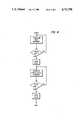
- FIG. 4is a flow chart illustrating the steps by which the bias and modulation current levels at which diode mode hopping occurs are identified in the present invention.
- FIG. 5is a schematic view showing the mode hopping control of the present invention in which laser diode bias and modulation currents are monitored to detect mode hop and provide signals for actuating a heating-cooling element to adjust diode temperatures and avoid mode hop.
- FIG. 1 of the drawingsthere is shown a Raster Output Scanner or ROS in which a high intensity laser beam 10, modulated in accordance with an image signal input, is scanned across a recording member 12 to selectively expose member 12. The image produced on the recording member 12 is thereafter developed to provide a visible image.
- a Raster Output Scanner or ROSin which a high intensity laser beam 10, modulated in accordance with an image signal input, is scanned across a recording member 12 to selectively expose member 12.
- the image produced on the recording member 12is thereafter developed to provide a visible image.
- Recording member 12may comprise any suitable recording medium such as the photoreceptor of a xerographic type imaging system. In systems of that type, the photoreceptor is first uniformly charged and then exposed by beam 10 to form a latent electrostatic image thereon as represented by the image signal input. The latent electrostatic image is thereafter developed and the developed image transferred to a suitable copy substrate material such as paper. Following transfer, the image is fixed as by fusing to form a permanent image. As will be understood, recording member 12 may be in any suitable form such as drum, web, belt, etc.
- Beam 10is generated by a suitable laser diode 15 which may for example comprise a Hitachi Model No. 7801E diode.
- An internal modulating circuitenables diode 15 to be modulated in accordance with an image signal input.
- the driving current for laser diode 15, which includes both bias and image signal modulation components,is input to diode 15 through line 18.
- the image signalsmay be obtained from any suitable source 17 such as comprise a memory, an input scanner, communication channel, character generator, etc..
- the modulated beam 10 output by diode 15passes through a suitable collimating lens 20 and a plane linear compensating grating 27 and impinges at an angle of substantially 45° on the grating facets 24 of a rotating holographic disc 22.
- Disc 22has a succession of facets 24 around the periphery thereof such that on rotation of disc 22 by motor 25, a first order beam 10-1 is scanned by each facet 24 across recording member 12 in the X direction.
- recording member 12is moved by a suitable drive means (not shown) in the Y direction (the direction shown by the solid line arrow in FIG. 1).
- a suitable lens 23is provided downstream of disc 22 for focusing beam 10 to a point on recording member 12.
- grating 27is a wavelength compensating device which has properties identical to the facet gratings formed on the surface of disc 22.
- grating 27is holographically formed using the same photorecording system. Accordingly, grating 27 has the same period as the disc grating facets and consequently has the same high diffraction efficiency as disc 22.
- Grating 27is placed in the tangential plane parallel to the plane of disc 22.
- the beam 10is still incident on grating 27 at angle ⁇ 1 i but is diffracted along a slightly different path, represented by the dotted line, at an angle ⁇ ' 1d .
- the pathis chosen at an exaggerated deviation angle for illustrative purposes.
- the beamis, however, shifted by a lateral distance S from the position of the first beam. This small lateral displacement is of no consequence since lens 23 focuses all image rays parallel entering it into the same point on the plane of recording member 12.
- the scanned linewill be corrected for errors in the cross scan or Y direction by grating 27.
- errors in the fast scan or X directionare only corrected at zero scan angle, i.e. when the beam is in the center angular rotation position of gratings 24 of disc 22.
- FIG. 2there is shown by graphical representation typical wavelength behavior of a laser diode such as diode 15 as a function of temperature.
- the modulationcauses a temperature excursion ⁇ T from the ambient temperature to some higher temperature. If the temperature excursion ⁇ T spans a temperature Th 1 , Th 2 , . . . Th n at which mode hopping takes place, then the laser will jump or mode hop to a different wavelength. For example, where the temperature excursion ⁇ T spans temperature Th 2 , then a mode hop from wavelength Wn 3 to Wn 4 occurs. If the ⁇ T excursion however lies between two mode hopping temperatures, for example between Th 1 and Th 2 , then no mode hop occurs and the beam output by laser diode 15 remains stable at a single wavelength.
- the scanner shown in FIG. 1is modified to detect and correct laser mode hopping.
- a pick-off mirror 50is provided to intercept the zero order or non-diffracted beam 10-0 passing through the facets 24 of disc 22 together with any shifted variant (identified herein as zero order beam 10-n) that results from a mode hop by diode 15.
- the first order beam 10-1is used to expose recording member 15 while the zero order beam 10-0 is typically impinged against a beam stop.
- mirror 50takes the place of the beam stop.
- the zero order beam 10-0 and any shifted beam 10-n that occurspass through lens 23, which is enlarged for this purpose, and impinge on a second mirror 53.
- Mirror 53reflects the zero order beam 10-0 and any shifted beam 10-n onto the surface 56 of a suitable beam position detector shown here as a linear sensor array 55 having a row or array of photosites in the form of photodiodes 57-1, . . . 57-n.
- a suitable beam position detectorshown here as a linear sensor array 55 having a row or array of photosites in the form of photodiodes 57-1, . . . 57-n.
- Other detector typessuch as a lateral photodiode may instead be contemplated.
- Lens 23focues the zero order beam 10-0, representing the no mode hop condition of laser diode 15 onto the surface 56 of array 55 at a preset point. It will be understood that the point where beam 10-0 impinges on the surface 56 of array 55 is determined by the characteristics of the scanner optical system, particularly mirrors 50,52 and lens 23.
- any shifted beam 10-n that occurs as a result of mode hop by laser diode 15is focused by lens 23 at a point on the surface 56 of sensor array 55 that is separate from the point where zero order beam 10-0 is focused. That is, in the event of a mode hop in which the excursion temperature ⁇ T of the laser diode spans a mode hop temperature (Th 1 , Th 2 , etc. in FIG. 2), the beam 10-n, which is shifted to a different wavelength (i.e. Wn 1 to Wn 2 , Wn 2 to Wn 3 , etc), impinges on the surface 56 of array 55 at a different point.
- the output of array 55is coupled by line 60 to a comparator circuit 65 which compares the current beam wavelength detected by array 55 with a pre-selected desired beam wavelength and outputs a control signal in response thereto to a suitable temperature control element 70.
- Temperature control element 70which may, for example, comprise a Peltier or thermoelectric heater/cooler placed in heat exchange relation with laser diode 15, regulates operating temperatures of diode 15.
- the controller 71 for temperature control element 70is coupled to the output of a comparator circuit 65 by line 72, controller 71 responding to the signal output of comparator circuit 65 to either heat or cool the diode 15 to maintain the diode low in the non-mode hop operating region.
- comparator circuit 65In order to maintain diode laser 15 in a temperature region in which mode hops do not occur, comparator circuit 65 must perform several functions. First, circuit 65 must determine or map the wavelength or photodiode positions at which mode hops (as shown in FIG. 2) occur during the start-up of the machine. This involves making a machine setup cycle in which a uniform temperature excursion of for example from 10° to 20° C. from ambient is made while noting the wavelengths at which large excursions of the beam 10-0 on the photodiodes of array 55 occur. Circuit 65 then chooses the largest temperature region between mode hops and thereafter controls laser diode temperature to stay within the chosen range.
- the FIG. 3 type of system for controlling laser diode temperatures to prevent mode hoppingmay be classified generally as a feedback system in which the output beam is monitored for evidence of mode hopping.
- the temperature control element 70is actuated to adjust the temperature of laser diode 15 to bring the diode temperature within the temperature excursion range ⁇ T where no mode hopping occurs.
- mode hoppingis terminated.
- the response timeis relatively slow, being of the order of approximately 1 sec., and it would be advantageous if mode hopping could be prevented or inhibited from happening in the first place.
- Temperature variations of the diode laser junctionare due to power dissipation variations resulting from both the bias and modulation components of the driving current to the diode.
- the bias component of the currentnormally controls the extinction level (usually in the range of spontaneous emission) of the laser diode energy output, while the modulation component of the current controls the information content of the energy output.
- the difference between these two componentscontrols the temperature excursion range of the laser diode junction (due to the difference in the power dissipated in the junction in the form of thermal energy). It has been found that fast (i.e. 1 microsec.) heating and/or cooling of the diode laser junction can be brought about by fast (i.e. 1 microsec.) changes in the drive or bias currents of the laser.
- a mode hopping lasermay be quickly stabilized to a single mode by adjusting the bias or modulation currents to change the junction operating temperature.
- an increase in currentwill work faster than a decrease and vice versa depending on whether the laser diode junction temperature is above or below the mode hopping temperature region T h .
- adjusting the temperature setpoint for the stabilized base of the laser diodewill carry the junction temperature excursion range ⁇ t into a region where mode hopping does not occur (as discussed earlier), this approach is as noted relatively slow (i.e., approx. 1 sec.).
- adjustment of the temperature setpointpermits setting the bias and modulation current parameters so as to optimize energy output from the laser diode while operating in a non-mode hopping region.
- the temperature limits that result from the bias and modulation currentsare set so as to control the energy output of the diode to retain diode operation in a non-mode hopping region.
- the laser diode junction wavelength versus temperature characteristiccontains a stable region of temperature excursion ⁇ T where adjusting of the bias and modulation currents may be employed without intruding into a mode hopping temperature region T h .
- the stable excursion temperature range ⁇ Twill be dependent on the laser diode junction characteristic, the desired current parameters, and the heat sink base temperature.
- the bias current on diode 15is decreased which in turn decreases the low end of the temperature excursion ⁇ T. It is noted in this respect that while the temperature excursion ⁇ T may increase, the average temperature and lowest bias temperature will nevertheless be reduced. If the decrease in diode temperatures causes the diode to enter a region of unstable operation, mode hopping will commence and thus the bias current (C bl ) at that point will identify the lower end of a stable temperature excursion range ⁇ T. The lowest bias current Cbl is suitably stored.
- the modulation current at which mode hopping occurs at the upper end of the stable temperature excursion range ⁇ Tmay be determined.
- the highest modulation current (C mh )is suitably stored. Therefore, by varying the bias and modulation currents of the laser diode and observing diode output for mode hopping, the currents at which mode hopping occurs may be determined for the temperature excursion range ⁇ T within which it is desired that the diode 15 operate.
- a suitable current sensor 80is provided to sense diode bias and modulation current levels in the line 18 to laser diode 15.
- the bias level signal (BIAS) and the modulation level signal (MOD) outputs of current sensor 80are fed to one input of bias and modulation current comparators 83, 84 respectively.
- a predetermined reference signal representing the previously determined lowest bias current (C bl ) at which mode hopping occursis placed on a second input of bias current comparator 83 while a predetermined reference signal representing the previously determined highest modulator current (C mh ) at which mode hopping occurs is placed on a second input of modulation current comparator 84.
- the outputs of comparators 83, 84are coupled by lines 87, 88, respectively to the heat and cool control inputs of controller 71 of temperature control element 70.
- comparator 84outputs a predetermined actuating signal to controller 71 of temperature control element 70. Controller 71 responds by actuating temperature control element 70 in the cooling mode to reduce the laser diode temperatures.
- comparator 83outputs a predetermined actuating signal to controller 71 of temperature control element 70. Controller 71 responds by actuating the temperature control element to raise diode temperatures.
- the bias and modulation current levels (C bl and C mh ) usedare slightly higher and lower respectively than the bias and current levels at which mode hopping has been found to occur.
- the control system of FIG. 3will detect the resulting mode hop and actuate temperature control element 70 in the manner described.
Landscapes
- Physics & Mathematics (AREA)
- General Physics & Mathematics (AREA)
- Optics & Photonics (AREA)
- Condensed Matter Physics & Semiconductors (AREA)
- Electromagnetism (AREA)
- Semiconductor Lasers (AREA)
- Optical Head (AREA)
- Dot-Matrix Printers And Others (AREA)
- Laser Beam Printer (AREA)
- Mechanical Optical Scanning Systems (AREA)
Abstract
Description
Claims (5)
Priority Applications (2)
| Application Number | Priority Date | Filing Date | Title |
|---|---|---|---|
| US06/882,122US4737798A (en) | 1986-07-03 | 1986-07-03 | Laser diode mode hopping sensing and control system |
| JP62159563AJPS6381317A (en) | 1986-07-03 | 1987-06-26 | Apparatus and method for detecting and removing mode hop of diode laser |
Applications Claiming Priority (1)
| Application Number | Priority Date | Filing Date | Title |
|---|---|---|---|
| US06/882,122US4737798A (en) | 1986-07-03 | 1986-07-03 | Laser diode mode hopping sensing and control system |
Publications (1)
| Publication Number | Publication Date |
|---|---|
| US4737798Atrue US4737798A (en) | 1988-04-12 |
Family
ID=25379931
Family Applications (1)
| Application Number | Title | Priority Date | Filing Date |
|---|---|---|---|
| US06/882,122Expired - LifetimeUS4737798A (en) | 1986-07-03 | 1986-07-03 | Laser diode mode hopping sensing and control system |
Country Status (2)
| Country | Link |
|---|---|
| US (1) | US4737798A (en) |
| JP (1) | JPS6381317A (en) |
Cited By (37)
| Publication number | Priority date | Publication date | Assignee | Title |
|---|---|---|---|---|
| US4792957A (en)* | 1986-12-22 | 1988-12-20 | Gte Communication Systems Corporation | Laser temperature controller |
| US4807992A (en)* | 1986-02-24 | 1989-02-28 | Fuji Photo Film Co., Ltd. | Method of detecting semiconductor laser mode hopping and semiconductor laser beam source apparatus |
| US4849980A (en)* | 1986-12-29 | 1989-07-18 | Fuji Photo Film Co., Ltd. | Laser beam recording method and apparatus |
| US4953951A (en)* | 1988-01-13 | 1990-09-04 | The United States Of America As Represented By The Secretary Of The Navy | Method for making holograms with coherent radiation from a stabilized laser diode that has been actively cooled |
| US5046840A (en)* | 1988-12-19 | 1991-09-10 | The Titan Corporation | Improvements in a system for determining atmospheric data relating to the movements of an airborne vehicle |
| US5073838A (en)* | 1989-12-04 | 1991-12-17 | Ncr Corporation | Method and apparatus for preventing damage to a temperature-sensitive semiconductor device |
| US5150371A (en)* | 1991-06-05 | 1992-09-22 | Xerox Corporation | Laser diode carrier with a semiconductor cooler |
| US5204694A (en)* | 1991-07-29 | 1993-04-20 | Xerox Corporation | Ros printer incorporating a variable wavelength laser |
| FR2683102A1 (en)* | 1991-07-08 | 1993-04-30 | Draegerwerk Ag | METHOD FOR OPERATING A LASER DIODE. |
| US5258821A (en)* | 1990-04-20 | 1993-11-02 | Photon, Inc. | Laser beam profiler having a multimode laser diode interferometer |
| EP0601757A1 (en)* | 1992-12-11 | 1994-06-15 | Xerox Corporation | Binary diffractive optical element scanner |
| US5379145A (en)* | 1989-12-01 | 1995-01-03 | Scientific-Atlanta, Inc. | Laser transmitter for light wave (fiber optic) communication espectially of AM modulated CATV signals having means . . . against damage |
| WO1997001203A1 (en)* | 1995-06-23 | 1997-01-09 | Coherent, Inc. | Temperature correction circuit for wavelength stabilization in a laser diode |
| US5646766A (en)* | 1991-06-07 | 1997-07-08 | Advanced Laser Technologies, Inc. | Laser beam scanning apparatus and method |
| US5781572A (en)* | 1995-10-25 | 1998-07-14 | Fujitsu Limited | Optical wavelength stabilizing system |
| US5861964A (en)* | 1991-03-27 | 1999-01-19 | Fujitsu Limited | Method of manufacturing light beam scanning apparatus and fixed hologram plate and rotatable hologram and light distributing apparatus |
| US5975419A (en)* | 1994-08-17 | 1999-11-02 | Metrologic Instruments, Inc. | Holographic laser scanner generating a high-resolution 2-D raster scanning pattern using a holographic scanning disc |
| US6134253A (en)* | 1998-02-19 | 2000-10-17 | Jds Uniphase Corporation | Method and apparatus for monitoring and control of laser emission wavelength |
| US6567433B2 (en) | 2000-10-10 | 2003-05-20 | Tunable Photonics Corporation | System and method for determining transmission wavelengths for lasers in a dense wavelength division multiplexer |
| US6611341B2 (en) | 2000-10-10 | 2003-08-26 | Spectrasensors, Inc. | Method and system for locking transmission wavelengths for lasers in a dense wavelength division multiplexer utilizing a tunable etalon |
| US6686586B2 (en) | 2001-03-23 | 2004-02-03 | Metrologic Instruments, Inc. | Diffractive-based laser scanning system employing microcontroller programmed for mode-switching correction in response to binary mode switching signal generation |
| US6693928B2 (en) | 2000-10-10 | 2004-02-17 | Spectrasensors, Inc. | Technique for filtering chirp from optical signals |
| US20040173780A1 (en)* | 2001-04-26 | 2004-09-09 | Nanogram Corporation | High luminescence phosphor particles and methods for producing the particles |
| US20060007970A1 (en)* | 2004-07-06 | 2006-01-12 | Paul Colbourne | Coherence reduction of diode lasers |
| US20060034004A1 (en)* | 2003-05-14 | 2006-02-16 | Eiji Sakamoto | Optical element holder, exposure apparatus, and device fabricating method |
| US20060268948A1 (en)* | 2000-10-10 | 2006-11-30 | Spectrasensors, Inc., A Delaware Corporation | Laser wavelength locker |
| US20070058221A1 (en)* | 2005-09-15 | 2007-03-15 | Lexmark International, Inc. | Systems and methods that compensate for scan path errors in a multi-beam electrophotographic imaging apparatus |
| US20080247429A1 (en)* | 2004-07-06 | 2008-10-09 | Paul Colbourne | Coherence reduction of diode lasers |
| US8339584B2 (en) | 2010-05-21 | 2012-12-25 | Teledyne Technologies Incorporated | Velocity measuring system |
| US9583135B1 (en) | 2016-04-27 | 2017-02-28 | Seagate Technology Llc | Laser mode hopping detection method and apparatus for a heat-assisted magnetic recording device |
| US9595288B1 (en) | 2016-05-16 | 2017-03-14 | Seagate Technology Llc | Laser mode hopping detection in a heat-assisted magnetic recording drive |
| US9916851B1 (en) | 2017-05-30 | 2018-03-13 | Seagate Technology Llc | Preheat strategy during sequential writing |
| US10283151B1 (en) | 2017-05-02 | 2019-05-07 | Seagate Technology Llc | Laser diode with integrated temperature control unit for a heat-assisted magnetic recording device |
| US10643651B1 (en) | 2018-10-17 | 2020-05-05 | Seagate Technology Llc | Determining instability zones of a laser of a heat-assisted magnetic recording head |
| US20210404908A1 (en)* | 2018-12-17 | 2021-12-30 | Nippon Telegraph And Telephone Corporation | Optical Deflector Parameter Measurement Device, Method, and Program |
| EP4080161A1 (en) | 2021-04-19 | 2022-10-26 | VITRONIC Dr.-Ing. Stein Bildverarbeitungssysteme GmbH | Method and device for compensating for beam angle variations of beams produced by a diffractive optical element |
| US12153997B2 (en) | 2022-07-08 | 2024-11-26 | Hand Held Products, Inc | Apparatuses, systems, and methods for visible laser diode preheat bias current for low temperature operation |
Citations (9)
| Publication number | Priority date | Publication date | Assignee | Title |
|---|---|---|---|---|
| US3588738A (en)* | 1968-09-03 | 1971-06-28 | Hughes Aircraft Co | Frequency stabilized laser |
| US3588254A (en)* | 1968-09-13 | 1971-06-28 | Gen Electric | Frequency control for tunable laser utilized in a position control system |
| US3790901A (en)* | 1972-03-22 | 1974-02-05 | Philco Ford Corp | Electro-optically induced weak coupling of adjacent carbon dioxide laser modes |
| US3902135A (en)* | 1971-09-29 | 1975-08-26 | Canon Kk | Laser oscillator with a wavelength stabilizing device |
| US4103254A (en)* | 1976-11-10 | 1978-07-25 | Chikami Leslie F | Tunable frequency laser |
| US4309671A (en)* | 1977-10-26 | 1982-01-05 | The Post Office | Control apparatus |
| US4428643A (en)* | 1981-04-08 | 1984-01-31 | Xerox Corporation | Optical scanning system with wavelength shift correction |
| US4625315A (en)* | 1984-08-27 | 1986-11-25 | Minnesota Mining And Manufacturing Company | Apparatus and circuitry for stabilizing laser diode output for analog modulation |
| US4683573A (en)* | 1985-09-24 | 1987-07-28 | Bell Communications Research, Inc. | Temperature stabilization of injection lasers |
Family Cites Families (2)
| Publication number | Priority date | Publication date | Assignee | Title |
|---|---|---|---|---|
| JPS60424A (en)* | 1983-06-17 | 1985-01-05 | Fujitsu Ltd | Waveform controlling system of optical beam scanner |
| JPS6113217A (en)* | 1984-06-29 | 1986-01-21 | Ricoh Co Ltd | Temperature control method for semiconductor laser in optical scanning device |
- 1986
- 1986-07-03USUS06/882,122patent/US4737798A/ennot_activeExpired - Lifetime
- 1987
- 1987-06-26JPJP62159563Apatent/JPS6381317A/enactivePending
Patent Citations (9)
| Publication number | Priority date | Publication date | Assignee | Title |
|---|---|---|---|---|
| US3588738A (en)* | 1968-09-03 | 1971-06-28 | Hughes Aircraft Co | Frequency stabilized laser |
| US3588254A (en)* | 1968-09-13 | 1971-06-28 | Gen Electric | Frequency control for tunable laser utilized in a position control system |
| US3902135A (en)* | 1971-09-29 | 1975-08-26 | Canon Kk | Laser oscillator with a wavelength stabilizing device |
| US3790901A (en)* | 1972-03-22 | 1974-02-05 | Philco Ford Corp | Electro-optically induced weak coupling of adjacent carbon dioxide laser modes |
| US4103254A (en)* | 1976-11-10 | 1978-07-25 | Chikami Leslie F | Tunable frequency laser |
| US4309671A (en)* | 1977-10-26 | 1982-01-05 | The Post Office | Control apparatus |
| US4428643A (en)* | 1981-04-08 | 1984-01-31 | Xerox Corporation | Optical scanning system with wavelength shift correction |
| US4625315A (en)* | 1984-08-27 | 1986-11-25 | Minnesota Mining And Manufacturing Company | Apparatus and circuitry for stabilizing laser diode output for analog modulation |
| US4683573A (en)* | 1985-09-24 | 1987-07-28 | Bell Communications Research, Inc. | Temperature stabilization of injection lasers |
Non-Patent Citations (4)
| Title |
|---|
| Wang et al.; "Measurement & Control of Subangstrom Mirror Displacement by Acousto-Optical Technique"; Rev. Sci., Instrum; 53(7); Jul. 1982; pp. 963-966. |
| Wang et al.; Measurement & Control of Subangstrom Mirror Displacement by Acousto Optical Technique ; Rev. Sci., Instrum; 53(7); Jul. 1982; pp. 963 966.* |
| Wittke et al.; "Stabilization of CW-Injection Lasers"; RCA Technical Notes; TN No. 1005; Apr. 9, 1975. |
| Wittke et al.; Stabilization of CW Injection Lasers ; RCA Technical Notes; TN No. 1005; Apr. 9, 1975.* |
Cited By (64)
| Publication number | Priority date | Publication date | Assignee | Title |
|---|---|---|---|---|
| US4807992A (en)* | 1986-02-24 | 1989-02-28 | Fuji Photo Film Co., Ltd. | Method of detecting semiconductor laser mode hopping and semiconductor laser beam source apparatus |
| US4792957A (en)* | 1986-12-22 | 1988-12-20 | Gte Communication Systems Corporation | Laser temperature controller |
| US4849980A (en)* | 1986-12-29 | 1989-07-18 | Fuji Photo Film Co., Ltd. | Laser beam recording method and apparatus |
| US4953951A (en)* | 1988-01-13 | 1990-09-04 | The United States Of America As Represented By The Secretary Of The Navy | Method for making holograms with coherent radiation from a stabilized laser diode that has been actively cooled |
| US5046840A (en)* | 1988-12-19 | 1991-09-10 | The Titan Corporation | Improvements in a system for determining atmospheric data relating to the movements of an airborne vehicle |
| US5379145A (en)* | 1989-12-01 | 1995-01-03 | Scientific-Atlanta, Inc. | Laser transmitter for light wave (fiber optic) communication espectially of AM modulated CATV signals having means . . . against damage |
| US5073838A (en)* | 1989-12-04 | 1991-12-17 | Ncr Corporation | Method and apparatus for preventing damage to a temperature-sensitive semiconductor device |
| US5258821A (en)* | 1990-04-20 | 1993-11-02 | Photon, Inc. | Laser beam profiler having a multimode laser diode interferometer |
| US6124955A (en)* | 1991-03-27 | 2000-09-26 | Fujitsu Limited | Light beam scanning apparatus |
| US6020999A (en)* | 1991-03-27 | 2000-02-01 | Fujitsu Limited | Light beam scanning apparatus |
| US5995250A (en)* | 1991-03-27 | 1999-11-30 | Fujitsu Limited | Method for manufacturing light beam scanning apparatus |
| US5978111A (en)* | 1991-03-27 | 1999-11-02 | Fujitsu Limited | Light beam scanning apparatus |
| US6091544A (en)* | 1991-03-27 | 2000-07-18 | Fujitsu Limited | Light beam scanning apparatus |
| US6020984A (en)* | 1991-03-27 | 2000-02-01 | Fujitsu Ltd. | Light beam scanning apparatus using a rotating hologram and a fixed hologram plate |
| US6040929A (en)* | 1991-03-27 | 2000-03-21 | Fujitsu Limited | Light beam scanning apparatus |
| US5973837A (en)* | 1991-03-27 | 1999-10-26 | Fujitsu Limited | Light distributing apparatus for dividing the light from a light source into a plurality of lights |
| US5861964A (en)* | 1991-03-27 | 1999-01-19 | Fujitsu Limited | Method of manufacturing light beam scanning apparatus and fixed hologram plate and rotatable hologram and light distributing apparatus |
| US5861989A (en)* | 1991-03-27 | 1999-01-19 | Fujitsu Limited | Light beam scanning apparatus |
| US5940195A (en)* | 1991-03-27 | 1999-08-17 | Fujitsu Limited | Light beam scanning apparatus |
| US5150371A (en)* | 1991-06-05 | 1992-09-22 | Xerox Corporation | Laser diode carrier with a semiconductor cooler |
| US5646766A (en)* | 1991-06-07 | 1997-07-08 | Advanced Laser Technologies, Inc. | Laser beam scanning apparatus and method |
| FR2683102A1 (en)* | 1991-07-08 | 1993-04-30 | Draegerwerk Ag | METHOD FOR OPERATING A LASER DIODE. |
| US5204694A (en)* | 1991-07-29 | 1993-04-20 | Xerox Corporation | Ros printer incorporating a variable wavelength laser |
| EP0601757A1 (en)* | 1992-12-11 | 1994-06-15 | Xerox Corporation | Binary diffractive optical element scanner |
| US5975419A (en)* | 1994-08-17 | 1999-11-02 | Metrologic Instruments, Inc. | Holographic laser scanner generating a high-resolution 2-D raster scanning pattern using a holographic scanning disc |
| US5754574A (en)* | 1995-06-23 | 1998-05-19 | Coherent, Inc. | Temperature correction circuit for wavelength stabilization in a laser diode |
| WO1997001203A1 (en)* | 1995-06-23 | 1997-01-09 | Coherent, Inc. | Temperature correction circuit for wavelength stabilization in a laser diode |
| US5781572A (en)* | 1995-10-25 | 1998-07-14 | Fujitsu Limited | Optical wavelength stabilizing system |
| US6134253A (en)* | 1998-02-19 | 2000-10-17 | Jds Uniphase Corporation | Method and apparatus for monitoring and control of laser emission wavelength |
| US6693928B2 (en) | 2000-10-10 | 2004-02-17 | Spectrasensors, Inc. | Technique for filtering chirp from optical signals |
| US6611341B2 (en) | 2000-10-10 | 2003-08-26 | Spectrasensors, Inc. | Method and system for locking transmission wavelengths for lasers in a dense wavelength division multiplexer utilizing a tunable etalon |
| US6567433B2 (en) | 2000-10-10 | 2003-05-20 | Tunable Photonics Corporation | System and method for determining transmission wavelengths for lasers in a dense wavelength division multiplexer |
| US6714309B2 (en) | 2000-10-10 | 2004-03-30 | Spectrasensors, Inc. | Method and system for locking transmission wavelengths for lasers in a dense wavelength division multiplexer |
| US6587484B1 (en) | 2000-10-10 | 2003-07-01 | Spectrasensor, Inc,. | Method and apparatus for determining transmission wavelengths for lasers in a dense wavelength division multiplexer |
| US7460567B2 (en) | 2000-10-10 | 2008-12-02 | Spectrasensors, Inc. | Laser wavelength locker |
| US20060268948A1 (en)* | 2000-10-10 | 2006-11-30 | Spectrasensors, Inc., A Delaware Corporation | Laser wavelength locker |
| US7227115B2 (en) | 2001-03-23 | 2007-06-05 | Metrologic Instruments, Inc. | Method of and system for detecting and correcting mode switching in diffractive-based laser scanning systems |
| US6686586B2 (en) | 2001-03-23 | 2004-02-03 | Metrologic Instruments, Inc. | Diffractive-based laser scanning system employing microcontroller programmed for mode-switching correction in response to binary mode switching signal generation |
| US20050018722A1 (en)* | 2001-03-23 | 2005-01-27 | Metrologic Instruments, Inc. | Method of and system for detecting and correcting mode switching in diffractive-based laser scanning systems |
| US7534994B2 (en) | 2001-03-23 | 2009-05-19 | Metrologic Instruments, Inc. | Laser scanning system employing laser mode switching using a binary mode switching signal |
| US20070295921A1 (en)* | 2001-03-23 | 2007-12-27 | Metrologic Instruments, Inc. | Method of and system for detecting and correcting mode switching in diffractive-based laser scanning systems |
| US20040173780A1 (en)* | 2001-04-26 | 2004-09-09 | Nanogram Corporation | High luminescence phosphor particles and methods for producing the particles |
| US20060034004A1 (en)* | 2003-05-14 | 2006-02-16 | Eiji Sakamoto | Optical element holder, exposure apparatus, and device fabricating method |
| US7116501B2 (en)* | 2003-05-14 | 2006-10-03 | Canon Kabushiki Kaisha | Optical element holder, exposure apparatus, and device fabricating method |
| US20080247429A1 (en)* | 2004-07-06 | 2008-10-09 | Paul Colbourne | Coherence reduction of diode lasers |
| US20060007970A1 (en)* | 2004-07-06 | 2006-01-12 | Paul Colbourne | Coherence reduction of diode lasers |
| US7668216B2 (en) | 2004-07-06 | 2010-02-23 | Jds Uniphase Corporation | Coherence reduction of diode lasers |
| US7570386B2 (en) | 2005-09-15 | 2009-08-04 | Lexmark International, Inc. | Systems and methods that compensate for scan path errors in a multi-beam electrophotographic imaging apparatus |
| US20070058221A1 (en)* | 2005-09-15 | 2007-03-15 | Lexmark International, Inc. | Systems and methods that compensate for scan path errors in a multi-beam electrophotographic imaging apparatus |
| US8339584B2 (en) | 2010-05-21 | 2012-12-25 | Teledyne Technologies Incorporated | Velocity measuring system |
| US8743351B2 (en) | 2010-05-21 | 2014-06-03 | Teledyne Technologies Incorporated | Velocity measuring system |
| US8804103B2 (en) | 2010-05-21 | 2014-08-12 | Teledyne Technologies Incorporated | Velocity measuring system |
| US9709594B1 (en) | 2010-05-21 | 2017-07-18 | Teledyne Technologies Incorporated | Velocity measuring system |
| US9792949B1 (en) | 2016-04-27 | 2017-10-17 | Seagate Technology Llc | Laser mode hopping detection method and apparatus for a heat-assisted magnetic recording device |
| US9583135B1 (en) | 2016-04-27 | 2017-02-28 | Seagate Technology Llc | Laser mode hopping detection method and apparatus for a heat-assisted magnetic recording device |
| US9595288B1 (en) | 2016-05-16 | 2017-03-14 | Seagate Technology Llc | Laser mode hopping detection in a heat-assisted magnetic recording drive |
| US10283151B1 (en) | 2017-05-02 | 2019-05-07 | Seagate Technology Llc | Laser diode with integrated temperature control unit for a heat-assisted magnetic recording device |
| US9916851B1 (en) | 2017-05-30 | 2018-03-13 | Seagate Technology Llc | Preheat strategy during sequential writing |
| US10643651B1 (en) | 2018-10-17 | 2020-05-05 | Seagate Technology Llc | Determining instability zones of a laser of a heat-assisted magnetic recording head |
| US20210404908A1 (en)* | 2018-12-17 | 2021-12-30 | Nippon Telegraph And Telephone Corporation | Optical Deflector Parameter Measurement Device, Method, and Program |
| US11656073B2 (en)* | 2018-12-17 | 2023-05-23 | Nippon Telegraph And Telephone Corporation | Optical deflector parameter measurement device, method, and program |
| EP4080161A1 (en) | 2021-04-19 | 2022-10-26 | VITRONIC Dr.-Ing. Stein Bildverarbeitungssysteme GmbH | Method and device for compensating for beam angle variations of beams produced by a diffractive optical element |
| US12306414B2 (en) | 2021-04-19 | 2025-05-20 | Vitronic Dr .-Ing. Stein Bildverarbeitungssysteme Gmbh | Method and device for compensating beam angle variations of a beam bundle of laser beams generated by a diffractive optical element |
| US12153997B2 (en) | 2022-07-08 | 2024-11-26 | Hand Held Products, Inc | Apparatuses, systems, and methods for visible laser diode preheat bias current for low temperature operation |
Also Published As
| Publication number | Publication date |
|---|---|
| JPS6381317A (en) | 1988-04-12 |
Similar Documents
| Publication | Publication Date | Title |
|---|---|---|
| US4737798A (en) | Laser diode mode hopping sensing and control system | |
| US4733253A (en) | Apparatus and method for detecting and eliminating diode laser mode hopping | |
| EP0134472B1 (en) | Laser beam scanner apparatus | |
| US5818857A (en) | Stabilized DFB laser | |
| JPH0689838A (en) | Dynamic control of individual spot exposure in optical output device | |
| US5283793A (en) | Laser beam recording apparatus | |
| JPH098390A (en) | Method and equipment for back face facet control of laser diode power output | |
| US6084894A (en) | Stabilized DFB laser | |
| CA2077813C (en) | Apparatus and method for spot position control in an output device employing a linear array of light sources | |
| US4699446A (en) | Dynamic power control for an external cavity stabilized laser diode in a holographic scanner | |
| US5543611A (en) | Method and apparatus for back facet monitoring of laser diode power output | |
| US4807992A (en) | Method of detecting semiconductor laser mode hopping and semiconductor laser beam source apparatus | |
| JPS6179286A (en) | Laser diode and mode hopping prevention therefor | |
| JPH0447829B2 (en) | ||
| JP2694989B2 (en) | Laser scanner | |
| JP2767618B2 (en) | Laser scanning optics | |
| JP2003266759A (en) | Image recorder and image recording method | |
| EP0618078A2 (en) | An optical scanning device | |
| JPH0445411A (en) | optical scanning device | |
| JPS61248658A (en) | Laser printer | |
| JP2682666B2 (en) | Optical scanning device | |
| JP3088441B2 (en) | Laser beam scanning device | |
| JPH0722321B2 (en) | Laser beam recording device | |
| JPS6123114A (en) | Temperature control method of semiconductor laser of optical scanning device | |
| JPS6113217A (en) | Temperature control method for semiconductor laser in optical scanning device |
Legal Events
| Date | Code | Title | Description |
|---|---|---|---|
| AS | Assignment | Owner name:XEROX CORPORATION, STAMFORD, CONNECTICUT A CORP. O Free format text:ASSIGNMENT OF ASSIGNORS INTEREST.;ASSIGNORS:LONIS, ROBERT A.;WRIGHT, NORMAN E.;REEL/FRAME:004575/0630 Effective date:19860623 | |
| STCF | Information on status: patent grant | Free format text:PATENTED CASE | |
| FPAY | Fee payment | Year of fee payment:4 | |
| FEPP | Fee payment procedure | Free format text:PAYOR NUMBER ASSIGNED (ORIGINAL EVENT CODE: ASPN); ENTITY STATUS OF PATENT OWNER: LARGE ENTITY | |
| FPAY | Fee payment | Year of fee payment:8 | |
| FPAY | Fee payment | Year of fee payment:12 | |
| AS | Assignment | Owner name:BANK ONE, NA, AS ADMINISTRATIVE AGENT, ILLINOIS Free format text:SECURITY INTEREST;ASSIGNOR:XEROX CORPORATION;REEL/FRAME:013153/0001 Effective date:20020621 | |
| AS | Assignment | Owner name:JPMORGAN CHASE BANK, AS COLLATERAL AGENT, TEXAS Free format text:SECURITY AGREEMENT;ASSIGNOR:XEROX CORPORATION;REEL/FRAME:015134/0476 Effective date:20030625 Owner name:JPMORGAN CHASE BANK, AS COLLATERAL AGENT,TEXAS Free format text:SECURITY AGREEMENT;ASSIGNOR:XEROX CORPORATION;REEL/FRAME:015134/0476 Effective date:20030625 | |
| AS | Assignment | Owner name:XEROX CORPORATION, CONNECTICUT Free format text:RELEASE BY SECURED PARTY;ASSIGNOR:JPMORGAN CHASE BANK, N.A. AS SUCCESSOR-IN-INTEREST ADMINISTRATIVE AGENT AND COLLATERAL AGENT TO JPMORGAN CHASE BANK;REEL/FRAME:066728/0193 Effective date:20220822 |