US4737036A - Device for whipping cream or egg whites or for preparing mayonnaise - Google Patents
Device for whipping cream or egg whites or for preparing mayonnaiseDownload PDFInfo
- Publication number
- US4737036A US4737036AUS06/875,320US87532086AUS4737036AUS 4737036 AUS4737036 AUS 4737036AUS 87532086 AUS87532086 AUS 87532086AUS 4737036 AUS4737036 AUS 4737036A
- Authority
- US
- United States
- Prior art keywords
- housing
- plunger
- plunger disc
- plate
- disc
- Prior art date
- Legal status (The legal status is an assumption and is not a legal conclusion. Google has not performed a legal analysis and makes no representation as to the accuracy of the status listed.)
- Expired - Fee Related
Links
- 239000006071creamSubstances0.000titleabstractdescription9
- 235000014103egg whiteNutrition0.000titleabstractdescription4
- 210000000969egg whiteAnatomy0.000titleabstractdescription4
- 239000008268mayonnaiseSubstances0.000titledescription3
- 235000010746mayonnaiseNutrition0.000titledescription3
- 238000004804windingMethods0.000claimsdescription9
- 238000007373indentationMethods0.000claimsdescription3
- 238000007599dischargingMethods0.000claims1
- 238000000034methodMethods0.000description3
- 230000004323axial lengthEffects0.000description1
- 238000010276constructionMethods0.000description1
- 239000013013elastic materialSubstances0.000description1
- 238000012986modificationMethods0.000description1
- 230000004048modificationEffects0.000description1
- 230000002093peripheral effectEffects0.000description1
- 238000007789sealingMethods0.000description1
- 229920003002synthetic resinPolymers0.000description1
- 239000000057synthetic resinSubstances0.000description1
Images

Classifications
- A—HUMAN NECESSITIES
- A23—FOODS OR FOODSTUFFS; TREATMENT THEREOF, NOT COVERED BY OTHER CLASSES
- A23G—COCOA; COCOA PRODUCTS, e.g. CHOCOLATE; SUBSTITUTES FOR COCOA OR COCOA PRODUCTS; CONFECTIONERY; CHEWING GUM; ICE-CREAM; PREPARATION THEREOF
- A23G3/00—Sweetmeats; Confectionery; Marzipan; Coated or filled products
- A23G3/02—Apparatus specially adapted for manufacture or treatment of sweetmeats or confectionery; Accessories therefor
- A23G3/0205—Manufacture or treatment of liquids, pastes, creams, granules, shred or powder
- A23G3/0215—Mixing, kneading apparatus
- A23G3/0221—Mixing, kneading apparatus with introduction or production of gas or under vacuum; Whipping; Manufacture of cellular mass
- A—HUMAN NECESSITIES
- A47—FURNITURE; DOMESTIC ARTICLES OR APPLIANCES; COFFEE MILLS; SPICE MILLS; SUCTION CLEANERS IN GENERAL
- A47J—KITCHEN EQUIPMENT; COFFEE MILLS; SPICE MILLS; APPARATUS FOR MAKING BEVERAGES
- A47J43/00—Implements for preparing or holding food, not provided for in other groups of this subclass
- A47J43/10—Egg-whisks; Cream-beaters, i.e. hand implements or hand-driven devices
- A47J43/1075—Hand-driven mixing devices with reciprocating or oscillating tools
- A47J43/1081—Hand-driven mixing devices with reciprocating or oscillating tools with rectilinearly reciprocating tools
- B—PERFORMING OPERATIONS; TRANSPORTING
- B01—PHYSICAL OR CHEMICAL PROCESSES OR APPARATUS IN GENERAL
- B01F—MIXING, e.g. DISSOLVING, EMULSIFYING OR DISPERSING
- B01F31/00—Mixers with shaking, oscillating, or vibrating mechanisms
- B01F31/44—Mixers with shaking, oscillating, or vibrating mechanisms with stirrers performing an oscillatory, vibratory or shaking movement
- B01F31/441—Mixers with shaking, oscillating, or vibrating mechanisms with stirrers performing an oscillatory, vibratory or shaking movement performing a rectilinear reciprocating movement
- B—PERFORMING OPERATIONS; TRANSPORTING
- B01—PHYSICAL OR CHEMICAL PROCESSES OR APPARATUS IN GENERAL
- B01F—MIXING, e.g. DISSOLVING, EMULSIFYING OR DISPERSING
- B01F33/00—Other mixers; Mixing plants; Combinations of mixers
- B01F33/50—Movable or transportable mixing devices or plants
- B01F33/501—Movable mixing devices, i.e. readily shifted or displaced from one place to another, e.g. portable during use
- B01F33/5011—Movable mixing devices, i.e. readily shifted or displaced from one place to another, e.g. portable during use portable during use, e.g. hand-held
- B01F33/50112—Movable mixing devices, i.e. readily shifted or displaced from one place to another, e.g. portable during use portable during use, e.g. hand-held of the syringe or cartridge type
- B—PERFORMING OPERATIONS; TRANSPORTING
- B01—PHYSICAL OR CHEMICAL PROCESSES OR APPARATUS IN GENERAL
- B01F—MIXING, e.g. DISSOLVING, EMULSIFYING OR DISPERSING
- B01F35/00—Accessories for mixers; Auxiliary operations or auxiliary devices; Parts or details of general application
- B01F35/30—Driving arrangements; Transmissions; Couplings; Brakes
- B01F35/32—Driving arrangements
- B01F35/32005—Type of drive
- B01F35/3202—Hand driven
Definitions
- the present inventionrelates generally to a hand-powered device for whipping cream or egg whites or for preparing mayonnaise.
- a device for whipping creamwhich is cup-shaped with a uniform cross-section over its entire length, such as a circular cross-section.
- a capreleasably closes the upper housing port.
- a plunger pistonhaving a plurality of axially parallel holes, is axially movable by a piston rod.
- the plunger pistonmoves within a circumferential clearance from the housing.
- the piston rodpasses through an accomodating slide rod bore in the cap and terminates outside the housing into a handgrip handle.
- a closable discharge openingis arranged at the bottom of the housing.
- the piston rodhas a length sufficiently long so that the plunger piston can be supported by the housing bottom.
- a manually operated device for whipping cream or egg whites and for preparing mayonnaisehas a housing to contain a product, means for whipping the product in the housing and including a plunger piston having a plurality of holes, and at least one plate having a plurality of holes and at least one plate being axially spaced from the plunger piston and axially movable relative to the latter.
- the inventionaccomplishes the task of improving the whipping process and achieving a complete discharge.
- the solutionlies in that there is provided one, preferably two, perforated discs, which are spaced away from the plunger piston on the piston rod.
- the discsare arranged one from another and are, for example, axially movable against, and limited by, spring tension.
- This arrangementhas the advantage in that a beated or whipped product located between perforated discs and the plunger piston can be expelled from this intermediate space by abutment of the perforated discs together against the plunger piston and against the innerside of the housing cap; for which purpose, however, the piston must be withdrawn.
- the coil springsare formed as conical springs. Specifically, the inner diameter of a respective subsequent winding is greater than the outer diameter of the previous small winding. In this manner, when a coil spring is fully compressed, its axial length becomes equivalent to the thickness of a winding.
- the perforated discshave coaxial indentations which accommodate the coil springs entirely in their compressed state.
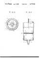
- FIG. 1shows a device, for example for whipping cream, in the front view partially broken up.
- FIG. 2shows a further embodiment in longitudinal view.
- FIG. 3shows a cross-sectional view taken across section lines III--III of FIG. 2.
- FIG. 4shows a variation of the same essentially in a longitudinal view.
- FIG. 1shows the device as having a substantially cup-shaped, cylindrical housing 1 with a preformed bottom 2.
- the longitudinal axis of the housing 1is perpendicular to the preformed bottom 2.
- a cap 3releasably locks the upper opening of the housing.
- a plunger piston 4is formed with a plurality of axially parallel holes 5.
- a piston rod 6is cylindrical and is arranged coaxial with respect to the housing 1 and to the plunger piston 4.
- the piston rod 6is movable axially through a slide-rod bore 7.
- the piston rod 6has a preformed, ring-shaped handle 8 at an end outside the housing 1.
- the handle 8is oval and larger than the size of a hand.
- the plunger piston 4has a diameter around 3 mm less than the inside diameter of the housing 1 so that the plunger piston 4 is arranged over its entire circumference with a 1.5 mm clearance with the inner side of the housing.
- a discharge opening 9is centrally located in the housing bottom 2, which, with its being constructed as a cover-like base plate, is releasably locked by a locking part 10.
- the locking part 10is releasably connected to the housing bottom 2 in a fashion similar to a bayonet catch.
- the circular-shaped discharge opening 9has two diametrally arranged notch openings 11.
- the locking part 10is formed as a cap which surrounds the outside of the housing 1.
- the piston rod 6 of the plunger piston 4adjoins two perforated discs 16 and 17 to the piston rod 6.
- the discs 16, 17are limited in their axial movement.
- the upper perforated disc 17is supported in the axial direction by a collar 18 of the piston rod 6.
- Coil springs 19 and 20, constructed as conical spiral springs,are arranged biasing respectively between the plunger piston 4 and the perforated disc 16 and between both perforated discs 16 and 17.
- the piston rod 6extends through the coil springs 19 and 20 from the side facing the plunger piston 4 and supports the perforated discs 16 and 17.
- the conical spiral-shaped coil springs 19 and 20are so constructed that each successive winding that all the windings could become compressed in a common plane.
- the compressed condition of the coil springs 1 and 20is shown with broken lines towards the top of FIG. 2, showing the least possible overall height they can have.
- the perforated discs 16 and 17could be formed with an indentation for receiving the coil springs 19 and 20. When the perforated discs become pressed together, the coil springs 19, 20 would then disappear into the contour of the perforated discs 16, 17.
- a releasably attached cover 21seals the holes 5 in the plunger piston 4.
- the cover 21has a preformed cuff 22 which envelops the circumference of the plunger piston 4.
- the cover 21, together with the cuff 22,are composed of soft elastic material and are detachably connected to the plunger piston 4. Moreover, the cuff 22 of the cover 21 seals the inner side of the housing 1.
- a nozzle 23is exchanged for the locking part 10 and attached to the discharge opening.
- the nozzle 23has the same locking mechanism as the locking part 10, namely a bayonet-like catch.
Landscapes
- Chemical & Material Sciences (AREA)
- Chemical Kinetics & Catalysis (AREA)
- Engineering & Computer Science (AREA)
- Food Science & Technology (AREA)
- Mechanical Engineering (AREA)
- Life Sciences & Earth Sciences (AREA)
- Polymers & Plastics (AREA)
- Food-Manufacturing Devices (AREA)
Abstract
Description
The present invention relates generally to a hand-powered device for whipping cream or egg whites or for preparing mayonnaise.
A device for whipping cream is known which is cup-shaped with a uniform cross-section over its entire length, such as a circular cross-section. A cap releasably closes the upper housing port. A plunger piston, having a plurality of axially parallel holes, is axially movable by a piston rod. The plunger piston moves within a circumferential clearance from the housing. The piston rod passes through an accomodating slide rod bore in the cap and terminates outside the housing into a handgrip handle. A closable discharge opening is arranged at the bottom of the housing. The piston rod has a length sufficiently long so that the plunger piston can be supported by the housing bottom.
With such an arrangement, the cream or similar product does not lend itself to a rapid whipping. Thus, the complete discharge from the housing is problematic.
It is the object of the present invention to improve the whipping process and yet still achieve a complete discharge from the housing.
In keping with this object, and others which will become apparent hereafter, one aspect of the invention resides, briefly stated, in a manually operated device for whipping cream or egg whites and for preparing mayonnaise. Such a device has a housing to contain a product, means for whipping the product in the housing and including a plunger piston having a plurality of holes, and at least one plate having a plurality of holes and at least one plate being axially spaced from the plunger piston and axially movable relative to the latter.
As described, the invention accomplishes the task of improving the whipping process and achieving a complete discharge. The solution lies in that there is provided one, preferably two, perforated discs, which are spaced away from the plunger piston on the piston rod. The discs are arranged one from another and are, for example, axially movable against, and limited by, spring tension.
This arrangement has the advantage in that a beated or whipped product located between perforated discs and the plunger piston can be expelled from this intermediate space by abutment of the perforated discs together against the plunger piston and against the innerside of the housing cap; for which purpose, however, the piston must be withdrawn.
Another advantage results when the coil springs are formed as conical springs. Specifically, the inner diameter of a respective subsequent winding is greater than the outer diameter of the previous small winding. In this manner, when a coil spring is fully compressed, its axial length becomes equivalent to the thickness of a winding.
Further, it is advantageous because the perforated discs have coaxial indentations which accommodate the coil springs entirely in their compressed state.
The novel features which are considered as characteristic for the invention are set forth in particular in the appended claims. The invention itself, however, both as to its construction and its method of operation, together with additional objects and advantages thereof, will be best understood from the following description of specific embodiments when read in connection with the accompanying drawings.
FIG. 1 shows a device, for example for whipping cream, in the front view partially broken up.
FIG. 2 shows a further embodiment in longitudinal view.
FIG. 3 shows a cross-sectional view taken across section lines III--III of FIG. 2.
FIG. 4 shows a variation of the same essentially in a longitudinal view.
Referring now to the drawings, FIG. 1 shows the device as having a substantially cup-shaped,cylindrical housing 1 with apreformed bottom 2. The longitudinal axis of thehousing 1 is perpendicular to thepreformed bottom 2. Acap 3 releasably locks the upper opening of the housing. Aplunger piston 4 is formed with a plurality of axiallyparallel holes 5. Apiston rod 6 is cylindrical and is arranged coaxial with respect to thehousing 1 and to theplunger piston 4. Thepiston rod 6 is movable axially through a slide-rod bore 7. Thepiston rod 6 has a preformed, ring-shaped handle 8 at an end outside thehousing 1. Thehandle 8 is oval and larger than the size of a hand.
Theplunger piston 4 has a diameter around 3 mm less than the inside diameter of thehousing 1 so that theplunger piston 4 is arranged over its entire circumference with a 1.5 mm clearance with the inner side of the housing.
Adischarge opening 9 is centrally located in thehousing bottom 2, which, with its being constructed as a cover-like base plate, is releasably locked by alocking part 10.
Thelocking part 10 is releasably connected to thehousing bottom 2 in a fashion similar to a bayonet catch. In addition, the circular-shaped discharge opening 9 has two diametrally arrangednotch openings 11. On the locking part's 10 side facing the bottom, there is apreformed plug 12 inserted into the discharge opening 9.Projections 13 protrude from the insertedplug 12 radially. Theseprojections 13 take hold of the rim of the discharge opening 9 from behind.
In order to guarantee a tight-sealing abutment of thelocking part 10 against the outer side of thehousing bottom 2, there are formed two ramps (not shown) which follow the edge of the discharge opening 9 inside of the housing and which rise in the peripheral and axial directions.
Outside of thelocking part 10 are two raised, right-angled intersections and preformedcross-bars 14 which determine a handle. Thecross-bars 14 are surrounded by a preformed cuff-like edge 15. Under the circumstances, it is especially advantageous in that thelocking part 10 is formed as a cap which surrounds the outside of thehousing 1.
According to FIG. 2, thepiston rod 6 of theplunger piston 4 adjoins two perforateddiscs piston rod 6. Thediscs disc 17 is supported in the axial direction by acollar 18 of thepiston rod 6.Coil springs 19 and 20, constructed as conical spiral springs, are arranged biasing respectively between theplunger piston 4 and the perforateddisc 16 and between both perforateddiscs piston rod 6 extends through thecoil springs 19 and 20 from the side facing theplunger piston 4 and supports theperforated discs
The conical spiral-shaped coil springs 19 and 20 are so constructed that each successive winding that all the windings could become compressed in a common plane. The compressed condition of thecoil springs
Further, theperforated discs coil springs 19 and 20. When the perforated discs become pressed together, thecoil springs 19, 20 would then disappear into the contour of theperforated discs
According to FIG. 4, a releasably attachedcover 21 seals theholes 5 in theplunger piston 4. Thecover 21 has apreformed cuff 22 which envelops the circumference of theplunger piston 4.
It is advantageous where the circumferential side of theplunger piston 4 is curve-shaped and thecuff 22 is shaped conforming to the circumferential side of theplunger piston 4.
Thecover 21, together with thecuff 22, are composed of soft elastic material and are detachably connected to theplunger piston 4. Moreover, thecuff 22 of thecover 21 seals the inner side of thehousing 1.
Here, anozzle 23 is exchanged for the lockingpart 10 and attached to the discharge opening. Thenozzle 23 has the same locking mechanism as the lockingpart 10, namely a bayonet-like catch.
All parts, with the exception of thepiston rod 6, are manufactured out of synthetic resin or plastic. It has been further found to be advantageous where the housing has a diameter of about 7 cm and a length of about 17 cm.
It will be understood that each of the elements described above, or two or more together, may also find a useful application in other types of manually operated devices for whipping cream and other products differing from the types described above.
While the invention has been illustrated and described as embodied in a manually operated device for whipping cream and other products, it is not intended to be limited to the details shown, since various modifications and structural changes may be made without departing in any way from the spirit of the present invention.
Without further analysis, the foregoing will so fully reveal the gist of the present invention that others can, by applying current knowledge, readily adapt it for the various applications without omitting features that, from the standpoint of prior art, fairly constitute essential characteristics of the generic or specific aspects of this invention.
Claims (17)
1. A device for whipping a product, comprising:
a housing to contain said product;
means for whipping said product in said housing and including a plunger piston having an axis and a plunger disc perpendicular to said axis, said plunger disc having a plurality of holes passing therethrough;
at least one plate having a plurality of holes and being axially spaced from said plunger disc and axially movable relative to the latter; and
means for biasing said plate relative to said plunger disc, said biasing means being arranged between said plate and said plunger disc, at least one of said plate and said plunger disc having an indentation formed to accomodate said biasing means in a fully compressed condition so that said plate and said plunger disc are in contact with each other when said biasing means is in said fully compressed condition to thereby effect a full explusion of the whipped product from between said plate and said plunger disc.
2. The device as defined in claim 1, wherein said plunger piston also includes a piston rod fixed to said plunger disc.
3. The device as defined in claim 2, wherein said housing is cup-shaped and has an open end; further comprising:
a cap closing said open end of said housing, said piston rod being axially movable through said cap.
4. The device as defined in claim 3, wherein said cap releasably engages said housing.
5. The device as defined in claim 2, wherein said piston rod is movable through said housing and has a portion formed as a handle outside of said housing.
6. The device as defined in claim 2, wherein said housing has a bottom and a top, said piston rod being movable through said top of said housing, said piston rod having a length long enough so that said plunger disc is movable to a closed position in which said plunger disc is supported by said bottom.
7. The device as defined in claim 1, wherein said housing has a length and a cross section which is uniform over its entire length.
8. The device as defined in claim 1, wherein said housing has a circular cross-section and said plate is disc-shaped.
9. The device as defined in claim 1, further comprising:
an additional plate having a plurality of holes and being arranged between said first mentioned plate and said plunger disc and spaced from said first mentioned plate and said plunger disc.
10. The device as defined in claim 9, wherein said first mentioned plate, said additional plate and said plunger disc each have a disc shape of equal diameter and are all coaxial with each other.
11. The device as defined in claim 8, wherein said additional plate is axially movable relative to said plunger disc.
12. The device as defined in claim 11, further comprising:
means for biasing said additional plate relative to said plunger disc; and
additional means for biasing said additional plate relative to said first mentioned plate.
13. The device as defined in claim 12, wherein said biasing means and said additional biasing means each include a conical coil spring, each of said springs having a plurality of windings of a diameter increasing in an axial direction.
14. The device as defined in claim 13, wherein each of said windings have an inner and an outer diameter such that said inner diameter of a subsequent one of said windings is greater than said outer diameter of a previous one of said windings.
15. The device as defined in claim 1, wherein said housing has a bottom end with an opening, said opening being openable for discharging said product and closeable for whipping said product, said plunger disc having a side facing said opening, further comprising:
a cover engagable on said side of said plunger disc to block said plurality of holes in said plunger disc so that said product is dischargable through said opening by said compressing means.
16. The device as defined in claim 15, further comprising:
at least one member releasable engagable with said bottom opening.
17. The device as defined in claim 16, wherein said opening has at least one notch, said member having an extended portion with at least one projection such that said extended portion and said projection fit into said opening and said notch respectively.
Applications Claiming Priority (2)
| Application Number | Priority Date | Filing Date | Title |
|---|---|---|---|
| DE3521384 | 1985-06-14 | ||
| DE3521384 | 1985-06-14 |
Publications (1)
| Publication Number | Publication Date |
|---|---|
| US4737036Atrue US4737036A (en) | 1988-04-12 |
Family
ID=6273292
Family Applications (1)
| Application Number | Title | Priority Date | Filing Date |
|---|---|---|---|
| US06/875,320Expired - Fee RelatedUS4737036A (en) | 1985-06-14 | 1986-06-16 | Device for whipping cream or egg whites or for preparing mayonnaise |
Country Status (1)
| Country | Link |
|---|---|
| US (1) | US4737036A (en) |
Cited By (53)
| Publication number | Priority date | Publication date | Assignee | Title |
|---|---|---|---|---|
| US5100241A (en)* | 1989-01-13 | 1992-03-31 | Chan Kwan Ho | Vacuum mixing/bone cement cartridge and kit |
| US5180083A (en)* | 1991-08-28 | 1993-01-19 | Carlson Michael A | Gel dispenser apparatus for expressing a flammable gel |
| US5580169A (en)* | 1994-11-22 | 1996-12-03 | Frabosk Casalinghi S.P.A. | Milk jug with froth-forming device for making "Cappuccino" and the like |
| US5780087A (en)* | 1996-09-23 | 1998-07-14 | Brady; Frank A. | Apparatus and method for frothing liquids |
| GB2321023A (en)* | 1997-01-10 | 1998-07-15 | Biesse Spa | Beating food products |
| USD409045S (en)* | 1998-04-01 | 1999-05-04 | Brady Frank A | In-cup frother |
| EP1062898A1 (en)* | 1999-06-24 | 2000-12-27 | Beniamino Holdings S.r.l. | Multi-purpose manually-operated device in particular for beverage preparation |
| US6200015B1 (en)* | 1999-02-26 | 2001-03-13 | The Pampered Chef, Ltd. | Mixing container |
| US6283627B1 (en) | 2000-09-12 | 2001-09-04 | Wayne G. Fromm | Drink mixer |
| US6322056B1 (en) | 1999-09-28 | 2001-11-27 | Gerhardt Van Drie | Submarine type liquid mixer with aeration |
| USD456205S1 (en) | 2000-04-18 | 2002-04-30 | Wayne G. Fromm | Milk frothing appliance |
| US20030047081A1 (en)* | 2001-09-13 | 2003-03-13 | Mcgonagle Gary | French press coffee maker with assembly to selectively reduce contact of grounds with liquid coffee |
| US6554259B2 (en) | 2000-03-08 | 2003-04-29 | Gerhardt Van Drie | High dissolved oxygen mixer-digester |
| US20040099315A1 (en)* | 2002-11-22 | 2004-05-27 | Peterson Francis C. | Method and apparatus for circulating fluids in a body of liquid |
| RU2257259C2 (en)* | 2001-12-18 | 2005-07-27 | Поляков Анатолий Сергеевич | Vibration mixer |
| US6926437B2 (en) | 2002-09-10 | 2005-08-09 | Gerhardt Van Drie | Gravity powered mixer system |
| RU2270055C1 (en)* | 2004-08-17 | 2006-02-20 | Алексей Николаевич Гладышев | Vibrating mixer |
| US20060209630A1 (en)* | 2005-03-15 | 2006-09-21 | Brown Craig E | Mixer for infant formula powder and other infant feeding products |
| US20060250887A1 (en)* | 2005-05-03 | 2006-11-09 | Vernon Robert D | Shaker with reciprocating agitator |
| RU2297274C1 (en)* | 2005-10-24 | 2007-04-20 | Государственное образовательное учреждение высшего профессионального образования "Братский государственный университет" | Rotary mixer with mechanical vibration exciter |
| US20080065088A1 (en)* | 2006-09-07 | 2008-03-13 | Wyeth | Bone Cement Mixing Systems and Related Methods |
| US20080144428A1 (en)* | 2005-02-23 | 2008-06-19 | Biomet Manufacturing Corp. | Method and Apparatus for Mixing Bone Cement |
| US20090043282A1 (en)* | 2005-04-29 | 2009-02-12 | Wyeth | Drug Delivery Devices and Related Components, Systems and Methods |
| US20090120306A1 (en)* | 2007-08-23 | 2009-05-14 | Decarlo John M | Systems and methods of mixing and cooling food products |
| RU2360730C1 (en)* | 2008-02-14 | 2009-07-10 | Алексей Николаевич Гладышев | Vibration mixer |
| US20090275121A1 (en)* | 2006-05-11 | 2009-11-05 | Sartorius Stedim Biotech Gmbh | Vibrational Mixer |
| RU2399486C1 (en)* | 2009-05-28 | 2010-09-20 | Государственное образовательное учреждение высшего профессионального образования "Братский государственный университет" | Device for concrete mix mixing |
| US20120210885A1 (en)* | 2011-02-18 | 2012-08-23 | International Business Machines Corporation | Food infuser device, system and method |
| US20120265209A1 (en)* | 2011-04-13 | 2012-10-18 | Kyphon Sarl | Apparatus and methods for mixing materials |
| US8313644B2 (en)* | 2010-01-13 | 2012-11-20 | OZOlab | Bottle with an integrated filtration assembly that is manually operated using a plunger |
| US20130125761A1 (en)* | 2008-05-07 | 2013-05-23 | SmartCup Inc. | Disposable Beverage Press |
| USD700008S1 (en)* | 2013-04-23 | 2014-02-25 | Hutzler Manufacturing Co., Inc. | Device for making whipped cream |
| US20140098629A1 (en)* | 2011-06-22 | 2014-04-10 | Medmix Systems Ag | Device for the low-bubble mixing and discharging of a product |
| CN103720388A (en)* | 2013-12-20 | 2014-04-16 | 苏州纺友新材料有限公司 | Labor-saving egg stirring cup |
| US20140110356A1 (en)* | 2012-10-19 | 2014-04-24 | Warsaw Orthopedic, Inc. | Filtration device |
| US20140119154A1 (en)* | 2011-10-27 | 2014-05-01 | Kasey Kershaw | Shakeable container with agitator |
| US20140202942A1 (en)* | 2013-01-23 | 2014-07-24 | Ecosphere Technologies, Inc. | Manual hydrodynamic cavitation water treatment device |
| DE102013017310A1 (en)* | 2013-07-02 | 2015-01-08 | Florian Enghard | Mixing bowl |
| RU2538868C1 (en)* | 2013-07-11 | 2015-01-10 | Федеральное государственное бюджетное образовательное учреждение высшего профессионального образования "Кубанский государственный технологический университет" (ФГБОУ ВПО "КубГТУ") | Mixing device |
| US20150216361A1 (en)* | 2014-01-31 | 2015-08-06 | Vim & Vigor Design Inc. | Device and method for mixing drinks |
| RU2598454C1 (en)* | 2015-05-12 | 2016-09-27 | федеральное государственное бюджетное образовательное учреждение высшего профессионального образования "Пермский государственный гуманитарно-педагогический университет" | Method of vibration control of heterogeneous density hydrodynamic systems in rotary containers |
| US20170043079A1 (en)* | 2010-10-14 | 2017-02-16 | Fresenius Medical Care Holdings, Inc. | Systems and methods for delivery of peritoneal dialysis (pd) solutions with integrated inter-chamber diffuser |
| USD804247S1 (en) | 2012-10-26 | 2017-12-05 | Trimr, Llc | Agitator on straw or rod for a shakable container |
| US20180110357A1 (en)* | 2016-10-24 | 2018-04-26 | Toby Eisenberg | French coffee press |
| US20180310974A1 (en)* | 2017-04-28 | 2018-11-01 | Heraeus Medical Gmbh | Bone cement application device with closure on the delivery plunger |
| US20180339248A1 (en)* | 2017-05-23 | 2018-11-29 | Kohler Co. | Water filter system |
| US10213053B2 (en)* | 2015-09-08 | 2019-02-26 | Adip Management, Llc | Whisk mixing systems within a container |
| US10799117B2 (en) | 2009-11-05 | 2020-10-13 | Fresenius Medical Care Holdings, Inc. | Patient treatment and monitoring systems and methods with cause inferencing |
| US10824326B2 (en) | 2009-01-16 | 2020-11-03 | Fresenius Medical Care Holdings, Inc. | Remote interfacing with a networked dialysis system |
| CN112121702A (en)* | 2020-09-22 | 2020-12-25 | 陈敏敏 | Blending device for agricultural technology pesticide research and development |
| WO2024010879A1 (en)* | 2022-07-06 | 2024-01-11 | Columbia Insurance Company | Apparatus for creating and dispensing whipped food products |
| US11998880B2 (en)* | 2020-09-01 | 2024-06-04 | Global Life Sciences Solutions Usa Llc | Collapsible agitator assembly for a bioprocessing system |
| US20240292979A1 (en)* | 2023-03-03 | 2024-09-05 | Sharkninja Operating Llc | Extrusion assembly for a micro-puree machine |
Citations (2)
| Publication number | Priority date | Publication date | Assignee | Title |
|---|---|---|---|---|
| DE333081C (en)* | 1919-04-23 | 1921-02-16 | Fritz Schmeckebier | Foam and snow hammer device |
| US3140078A (en)* | 1961-06-15 | 1964-07-07 | Adhesive Eng Co | Mixing and dispensing device |
- 1986
- 1986-06-16USUS06/875,320patent/US4737036A/ennot_activeExpired - Fee Related
Patent Citations (2)
| Publication number | Priority date | Publication date | Assignee | Title |
|---|---|---|---|---|
| DE333081C (en)* | 1919-04-23 | 1921-02-16 | Fritz Schmeckebier | Foam and snow hammer device |
| US3140078A (en)* | 1961-06-15 | 1964-07-07 | Adhesive Eng Co | Mixing and dispensing device |
Cited By (81)
| Publication number | Priority date | Publication date | Assignee | Title |
|---|---|---|---|---|
| US5100241A (en)* | 1989-01-13 | 1992-03-31 | Chan Kwan Ho | Vacuum mixing/bone cement cartridge and kit |
| US5180083A (en)* | 1991-08-28 | 1993-01-19 | Carlson Michael A | Gel dispenser apparatus for expressing a flammable gel |
| USRE37137E1 (en)* | 1994-11-22 | 2001-04-17 | Frabosk Casalinghi S.P.A. | Milk jug with froth-forming device for making “cappuccino”and the like |
| US5580169A (en)* | 1994-11-22 | 1996-12-03 | Frabosk Casalinghi S.P.A. | Milk jug with froth-forming device for making "Cappuccino" and the like |
| US5780087A (en)* | 1996-09-23 | 1998-07-14 | Brady; Frank A. | Apparatus and method for frothing liquids |
| US5939122A (en)* | 1996-09-23 | 1999-08-17 | Brady; Frank A. | Method for frothing liquids |
| GB2321023A (en)* | 1997-01-10 | 1998-07-15 | Biesse Spa | Beating food products |
| USD409045S (en)* | 1998-04-01 | 1999-05-04 | Brady Frank A | In-cup frother |
| US6200015B1 (en)* | 1999-02-26 | 2001-03-13 | The Pampered Chef, Ltd. | Mixing container |
| EP1062898A1 (en)* | 1999-06-24 | 2000-12-27 | Beniamino Holdings S.r.l. | Multi-purpose manually-operated device in particular for beverage preparation |
| US6322056B1 (en) | 1999-09-28 | 2001-11-27 | Gerhardt Van Drie | Submarine type liquid mixer with aeration |
| US6554259B2 (en) | 2000-03-08 | 2003-04-29 | Gerhardt Van Drie | High dissolved oxygen mixer-digester |
| US6599426B2 (en) | 2000-03-08 | 2003-07-29 | Gerhardt Van Drie | High dissolved oxygen mixer-digester method |
| USD456205S1 (en) | 2000-04-18 | 2002-04-30 | Wayne G. Fromm | Milk frothing appliance |
| US6283627B1 (en) | 2000-09-12 | 2001-09-04 | Wayne G. Fromm | Drink mixer |
| US20030047081A1 (en)* | 2001-09-13 | 2003-03-13 | Mcgonagle Gary | French press coffee maker with assembly to selectively reduce contact of grounds with liquid coffee |
| US6797304B2 (en) | 2001-09-13 | 2004-09-28 | Bonjour, Incorporated | French press coffee maker with assembly to selectively reduce contact of grounds with liquid coffee |
| RU2257259C2 (en)* | 2001-12-18 | 2005-07-27 | Поляков Анатолий Сергеевич | Vibration mixer |
| US6926437B2 (en) | 2002-09-10 | 2005-08-09 | Gerhardt Van Drie | Gravity powered mixer system |
| US20040099315A1 (en)* | 2002-11-22 | 2004-05-27 | Peterson Francis C. | Method and apparatus for circulating fluids in a body of liquid |
| US6814344B2 (en) | 2002-11-22 | 2004-11-09 | Nesson Enterprises | Method and apparatus for circulating fluids in a body of liquid |
| RU2270055C1 (en)* | 2004-08-17 | 2006-02-20 | Алексей Николаевич Гладышев | Vibrating mixer |
| US20080144428A1 (en)* | 2005-02-23 | 2008-06-19 | Biomet Manufacturing Corp. | Method and Apparatus for Mixing Bone Cement |
| US8029183B2 (en) | 2005-02-23 | 2011-10-04 | Biomet Manufacturing Corp. | Apparatus for mixing bone cement |
| US20060209630A1 (en)* | 2005-03-15 | 2006-09-21 | Brown Craig E | Mixer for infant formula powder and other infant feeding products |
| US20090043282A1 (en)* | 2005-04-29 | 2009-02-12 | Wyeth | Drug Delivery Devices and Related Components, Systems and Methods |
| US7441941B2 (en) | 2005-05-03 | 2008-10-28 | Robert D Vernon | Shaker with reciprocating agitator |
| US20060250887A1 (en)* | 2005-05-03 | 2006-11-09 | Vernon Robert D | Shaker with reciprocating agitator |
| RU2297274C1 (en)* | 2005-10-24 | 2007-04-20 | Государственное образовательное учреждение высшего профессионального образования "Братский государственный университет" | Rotary mixer with mechanical vibration exciter |
| US20090275121A1 (en)* | 2006-05-11 | 2009-11-05 | Sartorius Stedim Biotech Gmbh | Vibrational Mixer |
| US8342737B2 (en)* | 2006-05-11 | 2013-01-01 | Sartorius Stedim Biotech Gmbh | Vibrational mixer |
| US20080065088A1 (en)* | 2006-09-07 | 2008-03-13 | Wyeth | Bone Cement Mixing Systems and Related Methods |
| US20090120306A1 (en)* | 2007-08-23 | 2009-05-14 | Decarlo John M | Systems and methods of mixing and cooling food products |
| RU2360730C1 (en)* | 2008-02-14 | 2009-07-10 | Алексей Николаевич Гладышев | Vibration mixer |
| US9289091B2 (en)* | 2008-05-07 | 2016-03-22 | Smartcup, Inc. | Disposable beverage press |
| US20130125761A1 (en)* | 2008-05-07 | 2013-05-23 | SmartCup Inc. | Disposable Beverage Press |
| US11481105B2 (en) | 2009-01-16 | 2022-10-25 | Fresenius Medical Care Holdings, Inc. | Remote interfacing with a networked dialysis system |
| US10824326B2 (en) | 2009-01-16 | 2020-11-03 | Fresenius Medical Care Holdings, Inc. | Remote interfacing with a networked dialysis system |
| RU2399486C1 (en)* | 2009-05-28 | 2010-09-20 | Государственное образовательное учреждение высшего профессионального образования "Братский государственный университет" | Device for concrete mix mixing |
| US10799117B2 (en) | 2009-11-05 | 2020-10-13 | Fresenius Medical Care Holdings, Inc. | Patient treatment and monitoring systems and methods with cause inferencing |
| US8313644B2 (en)* | 2010-01-13 | 2012-11-20 | OZOlab | Bottle with an integrated filtration assembly that is manually operated using a plunger |
| US11779519B2 (en) | 2010-10-14 | 2023-10-10 | Fresenius Medical Care Holdings, Inc. | Systems and methods for delivery of peritoneal dialysis (PD) solutions with integrated inter-chamber diffuser |
| US20170043079A1 (en)* | 2010-10-14 | 2017-02-16 | Fresenius Medical Care Holdings, Inc. | Systems and methods for delivery of peritoneal dialysis (pd) solutions with integrated inter-chamber diffuser |
| US10842714B2 (en)* | 2010-10-14 | 2020-11-24 | Fresenius Medical Care Holdings, Inc. | Systems and methods for delivery of peritoneal dialysis (PD) solutions with integrated inter chamber diffuser |
| US20120210885A1 (en)* | 2011-02-18 | 2012-08-23 | International Business Machines Corporation | Food infuser device, system and method |
| US20120265209A1 (en)* | 2011-04-13 | 2012-10-18 | Kyphon Sarl | Apparatus and methods for mixing materials |
| US20140098629A1 (en)* | 2011-06-22 | 2014-04-10 | Medmix Systems Ag | Device for the low-bubble mixing and discharging of a product |
| US9643141B2 (en)* | 2011-10-27 | 2017-05-09 | Trimr, Llc | Shakeable container with agitator |
| US20140119154A1 (en)* | 2011-10-27 | 2014-05-01 | Kasey Kershaw | Shakeable container with agitator |
| US20170056850A1 (en)* | 2011-10-27 | 2017-03-02 | Trimr, Llc | Shakeable Container with Agitator |
| US9839888B2 (en)* | 2011-10-27 | 2017-12-12 | Trimr, Llc | Shakeable container with agitator |
| US9333447B2 (en)* | 2012-10-19 | 2016-05-10 | Warsaw Orthopedic, Inc. | Filtration device |
| US20140110356A1 (en)* | 2012-10-19 | 2014-04-24 | Warsaw Orthopedic, Inc. | Filtration device |
| USD828079S1 (en) | 2012-10-26 | 2018-09-11 | Trimr, Llc. | Shakable container with agitator |
| USD804247S1 (en) | 2012-10-26 | 2017-12-05 | Trimr, Llc | Agitator on straw or rod for a shakable container |
| USD871124S1 (en) | 2012-10-26 | 2019-12-31 | Trimr, Llc | Shakable container with an agitator |
| US9403697B2 (en)* | 2013-01-23 | 2016-08-02 | Ecosphere Technologies, Inc. | Manual hydrodynamic cavitation water treatment device |
| US20140202942A1 (en)* | 2013-01-23 | 2014-07-24 | Ecosphere Technologies, Inc. | Manual hydrodynamic cavitation water treatment device |
| USD700008S1 (en)* | 2013-04-23 | 2014-02-25 | Hutzler Manufacturing Co., Inc. | Device for making whipped cream |
| DE102013017310A1 (en)* | 2013-07-02 | 2015-01-08 | Florian Enghard | Mixing bowl |
| DE102013017310B4 (en) | 2013-07-02 | 2018-03-01 | Florian Enghard | Mixing bowl |
| US10588463B2 (en) | 2013-07-02 | 2020-03-17 | Florian Enghard | Mixing container |
| RU2538868C1 (en)* | 2013-07-11 | 2015-01-10 | Федеральное государственное бюджетное образовательное учреждение высшего профессионального образования "Кубанский государственный технологический университет" (ФГБОУ ВПО "КубГТУ") | Mixing device |
| CN103720388A (en)* | 2013-12-20 | 2014-04-16 | 苏州纺友新材料有限公司 | Labor-saving egg stirring cup |
| US20150216361A1 (en)* | 2014-01-31 | 2015-08-06 | Vim & Vigor Design Inc. | Device and method for mixing drinks |
| RU2598454C1 (en)* | 2015-05-12 | 2016-09-27 | федеральное государственное бюджетное образовательное учреждение высшего профессионального образования "Пермский государственный гуманитарно-педагогический университет" | Method of vibration control of heterogeneous density hydrodynamic systems in rotary containers |
| US10213053B2 (en)* | 2015-09-08 | 2019-02-26 | Adip Management, Llc | Whisk mixing systems within a container |
| US11771257B2 (en)* | 2016-10-24 | 2023-10-03 | Toby Eisenberg | French coffee press |
| US20240090698A1 (en)* | 2016-10-24 | 2024-03-21 | Toby Eisenberg | Improved french coffee press |
| US12408790B2 (en)* | 2016-10-24 | 2025-09-09 | Toby Eisenberg | French coffee press |
| US20210038015A1 (en)* | 2016-10-24 | 2021-02-11 | Toby Eisenberg | French coffee press |
| US10820739B2 (en)* | 2016-10-24 | 2020-11-03 | Toby Matthew Eisenberg | French coffee press |
| US20180110357A1 (en)* | 2016-10-24 | 2018-04-26 | Toby Eisenberg | French coffee press |
| US20180310974A1 (en)* | 2017-04-28 | 2018-11-01 | Heraeus Medical Gmbh | Bone cement application device with closure on the delivery plunger |
| US11103295B2 (en)* | 2017-04-28 | 2021-08-31 | Heraeus Medical Gmbh | Bone cement application device with closure on the delivery plunger |
| US11638891B2 (en)* | 2017-05-23 | 2023-05-02 | Kohler Co. | Water filter system |
| US20180339248A1 (en)* | 2017-05-23 | 2018-11-29 | Kohler Co. | Water filter system |
| US11998880B2 (en)* | 2020-09-01 | 2024-06-04 | Global Life Sciences Solutions Usa Llc | Collapsible agitator assembly for a bioprocessing system |
| CN112121702A (en)* | 2020-09-22 | 2020-12-25 | 陈敏敏 | Blending device for agricultural technology pesticide research and development |
| WO2024010879A1 (en)* | 2022-07-06 | 2024-01-11 | Columbia Insurance Company | Apparatus for creating and dispensing whipped food products |
| US20240292979A1 (en)* | 2023-03-03 | 2024-09-05 | Sharkninja Operating Llc | Extrusion assembly for a micro-puree machine |
Similar Documents
| Publication | Publication Date | Title |
|---|---|---|
| US4737036A (en) | Device for whipping cream or egg whites or for preparing mayonnaise | |
| US4648532A (en) | Mixing and discharge capsule | |
| US3776458A (en) | Telescopic drinking straw | |
| US3831742A (en) | Dental mixing capsule | |
| USRE37137E1 (en) | Milk jug with froth-forming device for making “cappuccino”and the like | |
| US3495703A (en) | Suture package | |
| EP0004100B1 (en) | A piston for ejecting a viscous or plastic mass | |
| US3675825A (en) | Self cleaning valve | |
| US4454037A (en) | Insulating jacket for an oil filter | |
| CA2401512A1 (en) | Device for chopping foodstuffs | |
| KR100267908B1 (en) | Multi-part dispenser | |
| US4182002A (en) | Meat tenderizer device | |
| US4537123A (en) | Device for pressing garlic and the like | |
| US3120678A (en) | Hamburger press | |
| US3128902A (en) | Histologic tissue receptacle | |
| GB2214785A (en) | Beverage infusing device | |
| US4436499A (en) | Household hand-device for use as meat-presser to shape mincement into steaks | |
| US3952685A (en) | Tow rope device | |
| US4227629A (en) | Detachable spout and closure | |
| US20190216203A1 (en) | Rotating mechanism of a cosmetic case | |
| US3749390A (en) | High speed amalgamator universal capsule holder | |
| EP0322828A1 (en) | Anti-drainage valve for oil filters for internal combustion engines | |
| US2694517A (en) | Cover closure device for containers | |
| GB2084862A (en) | Garlic press | |
| US2959391A (en) | Valve with sliding plunger |
Legal Events
| Date | Code | Title | Description |
|---|---|---|---|
| AS | Assignment | Owner name:HUTZLER MANUFACTURING COMPANY, INC., CANAAN, CT. 0 Free format text:ASSIGNMENT OF ASSIGNORS INTEREST.;ASSIGNOR:OFFERMANN, AXEL;REEL/FRAME:004685/0074 Effective date:19860814 | |
| FEPP | Fee payment procedure | Free format text:PAYOR NUMBER ASSIGNED (ORIGINAL EVENT CODE: ASPN); ENTITY STATUS OF PATENT OWNER: SMALL ENTITY | |
| FPAY | Fee payment | Year of fee payment:4 | |
| FEPP | Fee payment procedure | Free format text:PAT HOLDER CLAIMS SMALL ENTITY STATUS - SMALL BUSINESS (ORIGINAL EVENT CODE: SM02); ENTITY STATUS OF PATENT OWNER: SMALL ENTITY | |
| REFU | Refund | Free format text:REFUND OF EXCESS PAYMENTS PROCESSED (ORIGINAL EVENT CODE: R169); ENTITY STATUS OF PATENT OWNER: SMALL ENTITY | |
| REMI | Maintenance fee reminder mailed | ||
| LAPS | Lapse for failure to pay maintenance fees | ||
| FP | Lapsed due to failure to pay maintenance fee | Effective date:19960417 | |
| STCH | Information on status: patent discontinuation | Free format text:PATENT EXPIRED DUE TO NONPAYMENT OF MAINTENANCE FEES UNDER 37 CFR 1.362 |